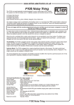
1
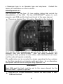
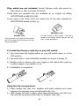
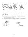
AutotetherTM Owner’s Manual Autotether, Inc. 3 Inspiration Lane, Unit B3 Chester, CT 06412 Phone: (888) 593-4181 Fax: (860) 526-9886 Email: [email protected] www.autotether.com TM US Patent #: 7201619 Revised December 2010 Information found in this document is subject to change without notice. Copyright AUTOTETHER, Inc. 2008 All rights reserved. Table of Contents Important Instructions 3 Getting Started 4 System Test 7 System Distance Check 8 Controls & Indicators 8 FOBs and Settings 10 Clip Identification & Installation 13 Operation 16 Operation – Detailed Outline 17 Alarm System 19 Troubleshooting 20 One Year Limited Warranty 21 1 Thank you for purchasing AUTOTETHER TM – the most advanced userfriendly wireless lanyard safety system on the water. Your AUTOTETHERTM system is a multifunctional 2.4 GHz radio integrated into an 8 bit microprocessor. This system has been designed to assist you and your guests in having a safer boating experience. The AUTOTETHERTM Wireless Lanyard Standard System comes with the following components: 1 Transmitter/Receiver (Host) with attached ignition switch clip 1 yellow Personal Sensor (FOB) for the operator 9 AAA Heavy Duty Batteries 1 Alcohol Cleaning Packet The Screamer Wireless Alarm System by Autotether comes with the following components: 1 Transmitter/Receiver (Host) Pulsating Alarm (105 dB) 1 Personal Sensor (FOB) 9 AAA Heavy Duty Batteries 1 Alcohol Cleaning Packet Before we get started, please pay attention to the following IMPORTANT INSTRUCTIONS Read the manual thoroughly and if you have any questions call Autotether support at (888)593-4181 2 Important Instructions Prior to setting up the system and starting your engine(s) make certain the area around the propeller(s) is clear; AUTOTETHERTM will not prevent drowning or being struck by a propeller. When boating, always wear a Coast Guard approved personal flotation device. If the system is not installed properly it may not stop the boat’s engine(s) as designed. AUTOTETHERTM wireless lanyard is only designed to work with factory installed, fully operational emergency stop (“kill”) switches. AUTOTETHER TM may not function properly if used with an aftermarket system or a malfunctioning system. Retain the Original Equipment kill switch clip on the vessel as a back-up safety device. Stopping the engine(s) may not stop the motion of the boat. AUTOTETHERTM does not provide a means to re-enter the vessel from the water. The distance at which the signal is diminished may depend on obstructions, other electromagnetic signals or other environmental conditions. Do not shield or cover the Fob with wet clothing, your arm, leg or another person or pets body, which may cause the Fob to act as if underwater, resulting in sudden accidental stopping of the vessel. If the Host case and/or gasket or the FOB case and/or gasket are damaged, the system may not function properly. The Host and the FOBs are water resistant to 3 feet (one meter) when the cases and gaskets are intact and properly installed. The Host unit and the FOBs DO NOT float. Part of the AUTOTETHERTM warning system is an audible, high pitch alarm. Hearing impaired individuals may not be able to hear the audio alarm. When picking up a person from the water, always use Coast Guard approved boating procedures and shut off the engine when the individual is within swimming distance from your vessel. Operating Temperature Range: 36°F -120°F 3 Getting Started Basic Operation. The AUTOTETHERTM wireless lanyard system comes with a transmitter (Host) that is attached to your vessel’s dashboard and one (1) yellow Personal Sensor (FOB) for the operator. Additional white passenger FOBs can be ordered from the AUTOTETHERTM website. AUTOTETHERTM can monitor up to four (4) FOBs simultaneously. Both the Host and each FOB are powered by AAA batteries. AUTOTETHERTM FOBs are worn by the vessel’s operator and up to three (3) passengers. When the Host is properly installed and activated, it automatically establishes communications with each active FOB and continuously monitors each active FOB. If an active yellow (operator) FOB is submerged for more than 1.5 seconds, the Host triggers the AUTOTETHERTM audible and flashing light alarm mode and shuts off the engine(s) by activating the spring-loaded AUTOTETHERTM kill switch clip, if an active white (passenger) Fob is submerged it will trigger the alarm mode only, allowing the operator to respond quickly and pick up the passenger. In addition, if an active and registered FOB goes beyond the Host detectable range (typically 50 to 200 feet) the appropriate FOB alarm mode will be triggered, or if the on/off button on an active and registered FOB is pushed and held for more than 2 seconds, the AUTOTETHERTM audio alarm sounds and the spring-loaded AUTOTETHERTM kill switch clip is triggered, shutting off the vessel’s engine(s) It is important to note that for both yellow and white FOBs, if the off button on the FOB is pushed and held for more than 2 seconds when they are registered with the Host this will trigger a full alarm mode shutting off the vessel kill switch. This is the only time when the white FOBs are capable of triggering the kill switch to shut off the engines Installing Batteries. AUTOTETHERTM comes with 9 AAA batteries. If batteries are not in box, they are installed in your system. If batteries are not installed, Using the screwdriver supplied with the AUTOTETHERTM System, remove the back covers from the Host and each FOB. The covers are designed to retain the screws so they can’t get lost. 4 Install six new (6) AAA batteries in the Host unit. Make certain to install the batteries according to the “+” and “-“ markings on the battery tray. Install three (3) new AAA batteries in the FOB. Make certain to install the batteries according to the “+” and “-“ markings on the battery tray. Once the batteries are properly installed, replace the back covers of the Host unit and the FOB. The Host unit back cover only installs in one direction. Make sure that screws are securely fastened while taking care not to overly tighten. NOTE Prior to replacing the battery covers, carefully inspect the gasket around the edge of Host unit and each FOB to make certain it is properly positioned. Remove batteries if unit will be in storage for more than 3 months. Mounting the Host Unit. Locate a flat surface within 12 inches of your vessel’s emergency stop (“kill”) switch. Make certain that the mounting area is clearly visible to the vessel operator. Clean the surface using the alcohol cleaning packet (provided). Peel the backing off of the Dual Lock strips located on the back of the Host unit. Carefully position the Host unit and press it into place. NOTE Once the Host unit has been pressed into place, it can be easily removed for storage or for use elsewhere by pulling it away from the mounting surface. DO NOT pull using the Host unit cord! Initializing the AUTOTETHERTM System. Once the batteries are installed and the Host unit is securely mounted, remove your Original Equipment clip from your vessel’s Emergency Stop (“kill”) switch 5 CAUTION DO NOT discard your Original Equipment clip! Store it near the engine start switch; it serves as a back-up to the AUTOTETHERTM System switch. On the end of the host unit cord you will find an actuator clip. Push the actuator clip onto the kill switch. As you push the actuator clip on, note that the plunger pin inside the end clip needs to be fully compressed and locked. You should hear a click when it locks. Because the clip is spring-loaded, it will take more force to position it on the switch than your Original Equipment clip. Press the recessed ON/OFF button on each FOB; the light on each FOB should illuminate steady GREEN. Press the POWER button on the Host unit – AUTOTETHERTM will automatically initiate a system check, battery test and searches for active FOBs. o Host POWER light flashes GREEN – HOST batteries are good o Host RESET light flashes AMBER - the system is searching for active FOBs WARNING!! If the POWER light is AMBER, the batteries are low and should be replaced. If the light is RED, batteries are dangerously low and must be replaced immediately. It is strongly recommended that all of the batteries in the AUTOTETHERTM system be replaced at the same time. The System is ready when: Host POWER light flashes GREEN – the HOST batteries are good The FOB Signal lights on the HOST flash GREEN for each FOB recognized The light on each FOB flashes GREEN every 4 seconds After about 2 minutes, the RESET light and the FOB Signal lights on the HOST will go out. The Host POWER light will continue to flash every 4 seconds to indicate that the system is on and operational. 6 System Test A complete system test should be performed before initially getting underway. This check is performed dockside with the vessel’s engine(s) OFF. Once the AUTOTETHERTM system is ready (POWER light GREEN; each active FOB light GREEN; and the Kill Switch actuator in place): Press the recessed ON/OFF button on anyone of the FOBs (operator or passenger FOB) for 2 seconds o The FOB will go to solid green and the corresponding Host LED will go solid RED for full alarm mode. o AUTOTETHERTM senses a “man overboard” condition (signal loss) o The AUTOTETHERTM alarm sounds o The Kill Switch actuator is triggered Press the RESET button on the Host to silence the alarm Re-engage the actuator clip on the Kill Switch If more than 3 minutes elapses while the FOB and Host are in alarm mode the FOB will turn itself off to save battery life, so turn on the deactivated FOB by pressing the recessed ON/OFF switch; FOB light will be steady GREEN again Press the Host POWER button to re-set the system o The Host will search for and recognized the re-activated FOB o FOB light flashes GREEN o Host POWER light flashes GREEN o Host FOB Signal lights flash GREEN for approximately 30 seconds, then goes out o Host RESET light flashes for approximately 30 seconds, then goes out Repeat this check for each FOB (maximum of 4) NOTE Disarm / Deactivate the Autotether Kill Switch Clip Actuator when the system is not in use. Disarmed 7 Armed System Distance Check A system distance check should be performed before initially getting underway. This procedure verifies system range. This check is performed dockside with the vessel’s engine(s) OFF. Once the AUTOTETHERTM system is ready (POWER light GREEN; each active FOB light GREEN; and the Kill Switch actuator in place): Take one activated FOB and walk away from the vessel until the AUTOTETHERTM alarm sounds. There should be a clear line of sight between the host and the FOB. o The FOB light will go from Flashing GREEN to Steady GREEN when the FOB has gone out of range NOTE The FOBs and Host communicate via a radio signal. If the signal is disrupted or goes beyond range, the AUTOTETHER TM alarm mode is activated. This procedure checks the range feature of the system. Radio signals are subject to interference by objects and various types of materials. For this reason, some variance in distance from the Host is acceptable. Return to vessel and press RESET button on Host to silence alarm Press Host POWER button to re-initialize system and register FOB Repeat this check for each FOB Controls & Indicators Host Controls and Indicators POWER Button o o Press the Power button to turn AUTOTETHERTM Host ON When the Host is turned ON, it automatically begins searching for FOBs to register If no FOBs are found after 3 minutes, the Host will turn itself OFF to conserve battery power If Host is on, press and hold POWER button for 2 seconds to turn Host OFF, this will also turn off all FOBs it is communicating automatically. There is no other way to turn off the FOBs other than turning off the HOST. 8 o If Host is on, press and hold POWER button for less than 2 seconds to start FOB search mode POWER Button Light (Light Emitting Diode (LED)) o Host OFF – LED OFF o o o o o o Host ON, no registered FOBs – LED steady on Host ON, at least one registered FOB – LED blinks If the battery is good (>7V) the LED is green. Flash time 4s. If the battery is low (>6V, <7V) the LED will be amber. 2s If the battery is bad (<6) the LED will flash red. 1.5s If the coil or the CAP is bad, the LED will be steady red. RESET Button o Press the RESET button to silence AUTOTETHERTM alarm o If system is not in alarm mode, RESET button has no effect. NOTE: LED Flash times indicate cycle time. On time is always 0.5s RESET Button LED o Host searching for FOBs – LED Flashing AMBER. 2 sec. o Alarm activated – LED Flashing RED. 1 sec. o In all other situations, this LED is off. FOB Signal/FOB Battery Level LED’s on Host o One LED for each FOB (4 maximum) o Host ON and FOB OFF or Unregistered – LED OFF FOB Registered & OK – LED Flash Green during Host search mode (1 second), then OFF FOB Registered, batteries low – LED flashes AMBER (1 second) during Host search mode, then OFF FOB registered, batteries bad – LED flashes RED (1 second) during Host search mode, then OFF FOB registered, signal interrupted – LED steady RED (alarm mode) If the host is not in search mode or alarm mode, the LEDs are off FOB Controls and Indicators POWER Button o Press to turn FOB ON 9 o If the Host is not found within 3 minutes, the FOB will automatically turn off to conserve battery power The FOB communicates with the Host every 0.5 seconds If the Fob is turned on and the ON/OFF switch is held for more than 2 seconds, the unit goes into an alarm mode. An alarm trips the actuator, audible alarm and flashing LEDs LED will go steady RED NOTE You cannot turn off the FOB with the power button on the FOB. The FOBs will automatically go off 3 minutes after no communication with the HOST. FOB LED o FOB OFF – LED OFF o FOB ON, Unregistered – LED steady GREEN o FOB ON, low batteries – LED flashing AMBER each 2 sec o FOB ON, batteries bad – LED steady RED o FOB ON, Registered – LED Flashing GREEN each 4 sec If a registered FOB goes out of range or the signal to the Host is interrupted, the LED will change to Steady GREEN until the FOB is re-registered with the Host If no Host is found after 3 minutes, FOB will turn itself OFF FOBs and Settings The AUTOTETHERTM Host can monitor a maximum of four (4) FOBs simultaneously. The Host and FOBs come channelized and pre-set from the factory for normal operation. Once the AUTOTETHER TM system is properly installed and activated, the FOBs and Host communicate with each other every 0.5 seconds. If that communication is interrupted, the alarm mode sounds and for the operator (yellow) FOB the kill switch actuator is triggered to stop the vessel’s engine(s). For proper AUTOTETHERTM operation and to prevent false alarms and inadvertent engine shutdown, it is critical that the FOBs be worn correctly by the vessel’s operator and the passengers. The FOB should be worn so that it has uninterrupted communication with the host 10 WARNING!! Covering a registered FOB with clothing, a flotation device, towel, with your arm or legs, another body of a person, or pet may cause a disruption in communication and inadvertently trigger the alarm and kill switch actuator After the AUTOTETHERTM system is installed and before getting underway for the first time, it is recommended that you check onboard Host/FOB communication by carrying a registered FOB around all parts of your vessel – including below deck and into the head. Pay attention to any areas onboard that cause disruption of Host/FOB communication. OPERATION If the FOB turns on and no host is available on the same radio channel within 3 minutes it will turn off. If the FOB sees a boot message from a host within 3 minutes, it will reset it’s timers and begin communication at the time slot indicated by its FOB_ID FOB will communicate with the host every 0.5s If it misses 2 communications with the host, it will wait for new synchronization from the host. If it has not been synchronized within 3 minutes it will turn itself off. If the Fob receives a turn-off command from the host, it will turn itself off. The FOB cannot be manually turned off. The Host automatically turns off the FOB when it is turned off. AUTOTETHERTM FOBs come pre-set at the factory for normal operation, however they can be tuned for specific purposes. Each FOB has 3 separate Dipswitches that control specific FOB functions. FOB Dipswitch # 2 Two (2) sliders that set the FOB identification for the Host Dipswitch #2 is set at the factory and is sealed. adjustment is necessary. No further Modifications to be representative only. Autotether performed by authorized FOB Dipswitch # 3 This Dipswitch can be used to change the characteristics of the FOB from 11 a Passenger type to an Operator type and vice/versa. factory for instructions on how to do this. . Contact the FOB Dipswitch # 4 FOB Dipswitch #4 has four (4), two position sliders that control the channelization of the FOB. For the AUTOTETHERTM system to work properly, each FOB and the Host must be set to the same channel. There is an identical four (4) position Dipswitch in the Host unit The Host and the FOBs channels are pre-set at the factory. In the rare occasion that two AUTOTETHERTM with the same frequency are operating in close proximity to each other, radio interference can occur and the units will operate erratically. This malfunction can be corrected by simply separating the two systems so that their signals do not interfere with each other. As an alternative, the system channel can be changed using Dipswitch #4. WARNING!! Each FOB and the Host must be set to the same channel for the AUTOTETHERTM system to operate. Using an A#1 Phillips screwdriver, remove the back covers of each FOB and the Host 12 Using the tip of the Phillips screwdriver, carefully re-position the Dipswitch sliders to set the same new channel in each of the FOBs and the Host. Check the gasket around each FOB and the Host and re-install the back covers. Test the AutotetherTM system for proper operation. Clip Identification and Installation Instructions 1.) Carefully match your existing clip from our lanyard to the ones supplied by AUTOTETHER TM. 2.) Before assembling the clip to your actuator, test it on your kill switch to be sure it fits. Once tested, attach it to the actuator. 3.) Be sure the small o-ring is in place in the end of the actuator. It will be held in place by the clip once it is installed in step 4. See DIA 1. 4.) You will see 2 tabs on the end of the actuator. Align the 2 tabs with the 2 slots in the clip and push the clip onto the actuator. Be sure you hear it snap into position (see DIA 1) 5.) Once the clip is in place hold the actuator in one hand, rotate the clip back and forth. It should move slightly. This indicates that the clip is seated properly. If it does not rotate slightly it has not been pushed down onto the actuator all the way. You will need to push the clip down further until it rotates slightly with very little resistance. 6.) If you need to remove a clip you must use the clip removal tools (which are supplied with your Autotether kit). You must use the clip removal tools or you will damage your Autotether unit and void the warranty. YAMAHA CLIP HONDA CLIP OMC 1 CLIP O-RING LOCATION BE SURE O-RING IS IN PLACE. DIA 1 OMC 2 CLIP MERCURY CLIP FOR CENTER CONSOLE MOUNTED KILL SWITCH 13 ACTUATOR TABS Clips which are not included: Suzuki, Mercury with side mount or tiller mount or tiller mounted kill switch. These clips are specials and are available at no charge by calling AUTOTETHER at 888-593-4181 If you have a clip which does not match any of the clips supplied by AUTOTETHER please contact us MERCURY CLIP For side mount or tiller mount. This clip is similar to the center mount clip but will not work in that application. SUZUKI CLIP This clip looks very much like the Honda clip. The Honda clip will not work for the Suzuki application To install the Mercury style clip on your kill switch: 1.) You must have the toggle switch on your kill switch down or in the OFF position. 2.) You must arm or cock Autotether actuator as shown in image 1b 3.) Position hole in mercury clip over toggle on kill switch then push up to place toggle in up position or on. 4.) Installation is completed. 1b 1a Using the clip removal tools: 1.) Place wedge tool (2a) over actuator and place wedges over seam between the actuator case and kill switch clip (2c). 2.) With wedge tool still in place, place tang compression tool (2b) over clip and line up pushers with tabs on actuator case (2d). 14 3.) Apply pressure to compression tool to push tabs in, at the same time apply pressure to wedge tool. The clip will release. 4.) Remove clip. 2a 2b 2c 2d Wedge Seam Pushers Tabs OPTIONAL: The loop on the actuator case is used to attach your existing red lanyard. This can provide an extra measure of security should you decide to use it this way. To use it: 1.) Attach the spring clip (provided) to the end of the red lanyard then place the spring clip onto the loop. 2.) Attach the other end of the lanyard to your belt or other adequate item on your body. 3 3 a Loop 15 a Spring clip Operation Once your AUTOTETHERTM system has been installed, turned on and tested, it’s ready for operation. The following scenarios are provided to give you an appreciation of the safety features provided by AUTOTETHERTM. Scenario # 1 – You are alone on the boat and getting ready to get underway. AUTOTETHERTM is ON and you are the operator and wearing your yellow FOB. The Host has registered the FOB, all system indicators are flashing GREEN and the kill switch actuator clip is installed. The engine is running as you move aft to pull up a fender. You trip and fall overboard. When the FOB you are wearing is submerged, the AUTOTETHER TM alarm sounds and the kill switch actuator is released, shutting the engine off. You climb back onboard. Press the RESET button to silence the alarm. Reconnect the kill switch clip and press the POWER button to re-initialize the system and register your FOB. Scenario # 2 – You are enjoying a day of boating with three passengers. You are all wearing your AUTOTETHER TM FOBs and the system is flashing GREEN. One of your passengers falls overboard. As soon as the AUTOTETHERTM FOB is submerged the AUTOTETHERTM alarm sounds and lights go steady red. You press the RESET button to silence the alarm. You maneuver to pick up your passenger, who is wearing a USCG approved flotation device. While you are maneuvering to pick up your passenger you notice that one of the FOB Signal LEDs is RED – it belongs to passenger who fell overboard. Everyone else in the boat is still being monitored by AUTOTETHERTM. Pick up your overboard passenger and, once the passenger is safely aboard, press the Host POWER button to re-initialize the system and register all of the FOBs. . NOTE DO NOT press Host POWER button while passenger is in the water – wait until passenger is safely recovered. If you press POWER button while passenger is in the water, the overboard passenger’s FOB will be recognized, until it goes back underwater, triggering the alarm 16 Operation – Detailed Outline OPERATION – SEARCH When the host is turned on it searches for FOBs. As soon as at least one FOB is registered, the system will be armed. If the host finds a FOB during its search, it will register the FOB and light up its associated LED. If the host finds all four FOBs it will stop searching After 3 minutes of searching, the host will stop searching. FOBs have been found it will turn itself off. If no FOB SURVEILLANCE OPERATION FOB and host will communicate every 0.5 seconds If the host misses two communications from the FOB, it will set itself into ALARM mode If the host gets an emergency alarm request from the FOB, it will set itself into ALARM mode CHARGE & ACTUATOR (HARDWARE) SELFTEST The host will monitor the capacitor voltage at the actuator to test charger circuit and presence of the actuator coil. If voltage stays below 90V for greater than 30 seconds, it will be a fault If the Voltage is greater than 106V for 3.5 seconds, it will be a fault If A/D converter self-test fails, it will be a fault ALARMS AND FAULTS ALARM OPERATION – LOST FOB (for wireless lanyard) (The audible alarm chirp is 0.5sec on, 0.5sec off) If a missing yellow (operator) FOB is registered, the actuator, audible alarm, and flashing LEDs will be tripped upon entering alarm mode. 17 If a missing white (passenger) FOB is registered, the audible alarm and flashing LEDs will be energized upon entering alarm mode. The RESET LED will be flashing red. (0.5sec on, 0.5sec off) If the RESET button is pressed, the audible alarm will be turned off, the missing FOB will be unregistered and surveillance will continue of the remaining FOBs. If the Power switch button is pressed (less than 2 s) during the alarm state, it will be ignored. Reset button must be pushed first before power switch button will respond. The system is immediately re-armed and will trip in the appropriate alarm mode again if a second FOB is lost. BATTERY FAULT – Host or Fob POWER LED blinks Red (for unit with bad battery), buzzer chirps (1sec on, 0.5sec off) Operation otherwise normal. CHARGE & ACTUATOR (HARDWARE) FAULT In Fault Condition, All LEDs blink Red, the buzzer chirps, the capacitor charging is disabled and the unit waits to be shut off. (2.5sec on 0.5sec off) TEST MODE (LEDs, BUZZER, SOFTWARE) FAULTS If the reset switch is held down for greater than 6 seconds and then the power switch is held down for greater than 1 second, unit enters test mode o In test mode, all LEDs will be amber, buzzer will be on for 1-2 seconds, then the unit will cause a software fault. o In software fault, after reset, buzzer chirps, the unit will reset and try to re-acquire fobs. 18 “The Screamer” Autotether Wireless Man Overboard Alarm System Operation All directions outlined above for the Standard Wireless Lanyard System apply to the Alarm System. The exceptions are: There is no kill switch clip. All FOBs have the same function. There is no function for FOB Dipswitch 2 or 3. FOB dipswitch 4 functions by changing channels in the alarm system. Operation (page 13) see below for the alarm operation. Alarms and Faults function is different with the alarm system, please see instructions below for The audible alarm is pulsating and much louder (105 dB) than the wireless lanyard system. Once your AUTOTETHERTM Alarm System is installed, turned on and tested, it’s ready for operation. Scenario # 1 – You are alone on the motorboat or sailboat and towing a dinghy and getting ready to get underway. AUTOTETHER TM is ON and a FOB has been placed in the dinghy. The Host has registered the FOB, all system indicators are flashing GREEN. Your dinghy breaks loose. When the FOB in the dinghy goes beyond approximately 150 feet the AUTOTETHERTM alarm sounds. You turn your boat around and go pick up your dinghy. Press the RESET button to silence the alarm. Once reattached to your boat press the POWER button to re-initialize the system and register your FOB. Scenario # 2 – You are enjoying a day or evening of sailing with several passengers. You are all wearing your AUTOTETHER TM FOBs and the system is flashing GREEN. One of your passengers falls overboard. As soon as the AUTOTETHERTM FOB is submerged the AUTOTETHERTM alarm sounds and lights go steady red. You press the RESET button to silence the alarm. You maneuver to pick up your passenger, who is wearing a USCG approved flotation device. While you are maneuvering to pick up your passenger you notice that one of the FOB Signal LEDs is RED – it belongs to the passenger who fell overboard. Everyone else in the boat is still being monitored by AUTOTETHERTM. You pick up your overboard passenger and, once the passenger is safely aboard, you press the Host POWER button to re19 initialize the system and register all of the FOBs. Troubleshooting The AUTOTETHERTM system is designed to be maintained by factory trained representatives. The system has extensive self-test capabilities. o The system will alert you when the batteries require changing. WARNING NEVER use partially discharged batteries. NEVER mix partially discharged batteries with new batteries Two AUTOTETHERTM systems operating close to each other on the same communication channel can cause erratic behavior. See the FOB Dipswitch #4 section of this manual to resolve this problem. If the YELLOW gasket installed on each FOB and the Host becomes damaged, please contact us for a replacement. For all other issues, please call us Toll Free at (888) 593-4181 The FCC Wants You To Know This device complies with part 15 of the FCC Rules. Operation is subject to the following two conditions: (1) This device may not cause harmful interference, and (2) this device must accept any interference received, including interference that may cause undesired operation. Changes or modifications to this product not expressly approved by Autotether, Inc., or operation of this product in any way other than as detailed by the owner’s manual, could void your authority to operate this product. This equipment has been tested and found to comply with the limits for a Class B digital device, pursuant to part 15 of the FCC Rules. These limits are designed to provide reasonable protection against harmful interference in a residential installation. This equipment generates uses and can radiate radio frequency energy and, if not installed and used in accordance with the instructions, may cause harmful interference to radio communications. However, there is no guarantee that interference will not occur in a particular installation. If this equipment does cause 20 harmful interference to radio or television reception, which can be determined by turning the equipment off and on, the user is encouraged to try to correct the interference by one or more of the following measures: Reorient or relocate the receiving antenna. Increase the separation between the equipment and receiver. Connect the equipment into an outlet on a circuit different from that to which the receiver is connected. Consult the dealer or an experienced radio/ TV technician for help. One Year Limited Warranty Evidence of original purchase is required for warranty service. Autotether, Inc. (Autotether) warrants for a period of one year, to the original retail owner this Autotether product to be free from defects in materials and craftsmanship with only the limitations or exclusions set out below. The warranty to the original owner shall terminate and be of no further effect 12 months after the date of the original retail sale. The warranty is invalid if the product is (A) damaged or not maintained as reasonable or necessary, (B) modified or altered, or used as part of any conversion kits, subassemblies, or any configuration not sold by Autotether, (C) improperly installed, (D) serviced or repaired by someone other than an authorized Autotether service personal for a defect or malfunction covered by this warranty, (E) used in any conjunction with equipment or parts or as part of any system not manufactured by Autotether, or (F) installed or programmed by anyone other than as detailed by the owner’s manual for this product. Statement of Remedy: In the event this product does not conform to this warranty at any time while this warranty is in effect, warrantor will either, at its option, repair or replace the defective unit and return it to you without charge for parts, service, or any other cost (except shipping and handling) incurred by warrantor or its representative in conjunction with the performance of this warranty. Warrantor, at its option, may replace the unit with a new or refurbished unit. The limited warranty set forth above is the sole and entire warranty pertaining to the product and is in lieu of and excludes all other warranties of any nature whatsoever, whether express, implied or arising by operation of law, including, but not limited to any implied warranties of merchantability or fitness for a particular purpose. This warranty does 21 not cover or provide for the reimbursement or payment of incidental or consequential damages. Legal remedies: This warranty gives you specific legal rights, and you may also have other rights which vary from state to state. Procedure for obtaining performance of warranty: If after following the instructions in the owner’s manual you are certain the product is defective, call customer service, toll free at (888) 593-4181 to obtain a Return Authorization Number (RAN). Remove the batteries from the units and pack the product with the batteries carefully (preferably in its original packaging). The product should include all parts and accessories originally packaged with the Product. Include evidence of original purchase and a note describing the defect that has caused you to return it. The Product should be shipped freight prepaid, by traceable means, to: Autotether, Inc. RAN: (insert Return Authorization Number) 3 Inspiration Lane, Unit B3 Chester, CT 06412 30-Day Money Back Guarantee Evidence of original purchase directly from Autotether, Inc. is required for the money back guarantee thirty days of the Autotether product. This money back guarantee does not apply to customers who purchased a system from one of our dealers or other vendor. If the customer is not satisfied with product they may return the product with only the limitations or exclusions set out below. The money back guarantee to the original owner shall terminate and be of no further effect 30 days after the date of the original retail sale. The guarantee is invalid if the product is (A) damaged or not maintained as reasonable or necessary, (B) modified or altered, or used as part of any conversion kits, subassemblies, or any configuration not sold by Autotether, (C) improperly installed, (D) serviced or repaired by someone other than an authorized Autotether service personal for a defect or malfunction, (E) installed or programmed by anyone other than as detailed by the owner’s manual for this product. Statement of Remedy: The customer may return their unit within 30 days of retail sale as long as they have not invalidated the guarantee as listed above. Autotether will refund the customer the amount paid for 22 their purchase excluding shipping and handling costs. The guarantee set forth above is the sole and entire money back guarantee pertaining to the product and is in lieu of and excludes all other guaranties of any nature whatsoever, whether express, implied or arising by operation of law, including, but not limited to any implied warranties of merchantability or fitness for a particular purpose. Call customer service, toll free at (888) 593-4181 to obtain a Return Authorization Number (RAN). Remove the batteries from the units and pack the product with the batteries carefully (preferably in its original packaging). The product should include all parts and accessories originally packaged with the Product. Include evidence of original purchase and a note describing the defect or issue that has caused you to return it. The Product should be shipped freight prepaid, by traceable means, to: Autotether, Inc. RAN: (insert Return Authorization Number) 3 Inspiration Lane, Unit B3 Chester, CT 06412 23 AUTOTETHERTM BOAT SAFER. BOAT SMARTER. Questions? Please contact us using our toll free number or through email. We look forward to hearing from you! Autotether, Inc. 3 Inspiration Lane, Unit B3 Chester, CT 06412 Phone:(888) 593-4181 Fax:(860) 526-9886 Email: [email protected] www.autotether.com US Patent #: 7201619 Revised December 2010