1
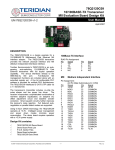
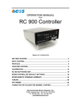
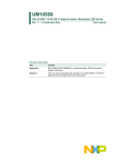
User's Guide
SNOA476C – October 2006 – Revised April 2013
AN-1521 POEPHYTEREV-I / -E Evaluation Board
1
Introduction
The POEPHYTEREV-I/-E evaluation board is a seamless design demonstrating Texas Instruments
LM5072 PoE product (capable of up to 24W) and DP83848I (single port 10/100Mb/s) Ethernet PHYTER®
product. While both the LM5072 and the DP83848 Ethernet PHY device have many advanced and
enticing features, this specific board is designed to demonstrate a subset of those features, specifically
Power over Ethernet. Two versions of this board are available. The –I version has an RJ-45 connector that
with integrated Ethernet magnetics. The –E version has discrete RJ-45 connector and Ethernet magnetics.
The schematics of the board are available with this kit for duplication into an end application product.
For additional features of the PoE and PHY devices, individual device evaluation boards are separately
available. For detailed information about the complete functions and features of the LM5072 or DP83848
devices, refer to the relevant data sheets. For applications where IEEE 802.3af must be complied with and
the power level is below 12.95W, refer to AN-1455 LM5072 Evaluation Board (SNVA154). For detailed
information about the Ethernet PHYTER® circuit, refer to AN-1469 PHYTER® Design & Layout Guide
(SNLA079).
This evaluation kit contains:
• POEPHYTEREV-I or –E Evaluation board
• Printed copy of this User's Guide
• Board schematic
• End User Licensing Agreement (EULA)
2
Scope of Applications
The POEPHYTEREV-I/-E evaluation kit (EK) is designed for high power PD (PoE terminology - Powered
Device) applications in which the maximum power exceeds the IEEE 802.3af’s 12.95W limit. The
evaluation board features TI™’s DP83848 10/100 Mb/s PHYTER® Ethernet Physical Layer Transceiver,
so any equipment that provides a standard IEEE 802.3, Clause 22 MII DTE interface; e.g.
SmartBits/Netcom box, is required as a data source for the Ethernet device. The LM5072 is a 100V, high
power PoE PD and PWM controller. The evaluation board is capable of operating with both PoE and
auxiliary (AUX) power sources. The dc-dc converter stage of the power supply is implemented in the
versatile flyback converter topology.
3
Important Note on Circuit Board Versions
There are two versions of PCBs being built, which can be identified by the PCB serial number printed
along the left edge of the top side the circuit board. One version is labelled 551012916-001 Rev A, the
other 551013040-001 Rev A. The first version cannot modify the 3.3V output to higher voltages because it
is directly connected to the PHY through inner layers. It is modified on the second version such that higher
output voltage can be produced without damaging the PHY circuit. The factory default output setting for
both versions is 3.3V. Contact TI on support to modify the latter version to other output voltage.
In the following, descriptions apply to both versions of the circuit boards unless specifically indicated.
TI is a trademark of Texas Instruments.
All other trademarks are the property of their respective owners.
SNOA476C – October 2006 – Revised April 2013
Submit Documentation Feedback
AN-1521 POEPHYTEREV-I / -E Evaluation Board
Copyright © 2006–2013, Texas Instruments Incorporated
1
Features of the Evaluation Board
4
www.ti.com
Features of the Evaluation Board
Seamless design solution, incorporating DP83848 PHYTER® single port 10/100 Mb/s Ethernet physical
layer transceiver and LM5072 High Power PoE PD and PWM controller.
Ethernet
• Integrated or External magnetics and RJ45
• Minimum configuration requirements:
–
2 PHY Addresses - 01h (default) or 03h
–
Status LEDs – board power, others dependant on LED mode selected
–
Limited Strap Options – MDIX_EN, LED_CFG, PWR_DWN/INT, MII/RMII Sel
–
RESET_N jumper
–
PWR_DWN/INT jumper
• Connections for the following interfaces:
–
MIl/RMII Interface (IEEE 802.3 standard)
–
RJ-45 Cat-V Ethernet cable connector
–
JTAG header
–
25MHz_OUT header
–
Header for “ribbon cable” connection to MII/RMII
• On-board clock – Crystal/Oscillator Dual Footprint
Power Over Ethernet
• Isolated output voltage: 3.3V
• Maximum output current: 7.3A
• Maximum output power: 24W
• Input voltage ranges:
–
PoE input voltage range: 39 to 57V
–
AUX input voltage range: 22 to 57V
• Measured maximum efficiency:
–
DC to DC converter efficiency: 90% at 6A
–
Overall efficiency (including the input diode bridge): 86% at 6A
• Overall Board Size: 5.50” x 3.96” x 0.70”
• Switching frequency: 250 kHz
• Optional input common-mode filter
PCB Layout Considerations
• FR4 material
• Trace symmetry within differential pair (±0.5")
• Differential impedance 100 ohms, ±5%
• Adjacent differential pairs spacing > 2X distance within a differential pair, to minimize cross-talk and
EMI
• Trace length matching between differential pairs not required
• Uniform supply & ground plane
• Void planes under magnetics, except for Chassis GND (at RJ-45 edge only)
• Combination of through-hole and surface mount technology
• Trace/space will be 0.007”/0.008” minimum
• System interface will be via the MII connector, and MII header
• RJ-45 for network connection
• JTAG access via 2x5 header
2
AN-1521 POEPHYTEREV-I / -E Evaluation Board
SNOA476C – October 2006 – Revised April 2013
Submit Documentation Feedback
Copyright © 2006–2013, Texas Instruments Incorporated
Usage setup and Configuration
www.ti.com
5
Usage setup and Configuration
This section contains information about the setup and configuration of the POEPHYTEREV-I/-E evaluation
board, including descriptions of the card's interfaces, connectors, jumpers and LEDs.
Power for the POEPHYTEREV board can be supplied by a number of means:
• MII connector J1
• PoE over unused pairs
• PoE over data pairs
• External supply to P1
• If 5V is supplied from the MII connector, the on-board voltage regulator, U2, will convert 5V to 3.3V for
the PHYTER®. J7 should be removed.
• If 3.3V is supplied from the MII connector, J7 needs to be ON (see Section 8 for details).
• Only applies to the circuit board version with PCB serial number 551013040-001 Rev A: J7 should be
shorted if the PoE main output is set at 3.3V, which is the default factory setting. To modify the output
to other higher voltages, a 3.3V LDO should be installed onto U2 and J7 must be open.
Address Settings:
The PMD address for the DP83848 Physical Layer device is set by jumper J3.
• Default board setting for the PHY Address is 01h
• The board may be set to PHY Address 03h by adding jumper J3
Table 1. Table of Jumpers (1)
Jumper
Name
Function
J1
MII Male Connector
J2
MII Header
J3
PHYAD1
PHY Address strap pin
J4
MDIX_EN
Enable/Disable MDIX mode. (Default is Auto-MDIX Enable)
J5
LED_CFG
Set LED configuration. See data sheet
MII interface
Alternative connection for MII signals
J6(Not populated)
J7
MII 3V3 option
Use 3V3 MII supply
J8
PWR_DWN/INT
J9
RESET_N
Reset the device
Pulse Jack
Integrated Magnetic RJ-45 connector
Set Power Down and Interrupt Mode. See data sheet
J10 (Not populated)
J11 (Not populated)
J12
(1)
Additional information for all options above may be found in the DP83848 data sheet.
Status indicators: LEDs
The POEPHYTEREV board supplies numerous status indicators via LEDs.
Status provided include:
Link - DS3*
Media Speed - DS2
Activity/Collision - DS4*
Ethernet Device Power - DS1
PoE Power - LED1
*Other status can be indicated by these LEDs. The alternate status is set by adding jumper J5. Refer to
PHYTER Extreme Temperature Single Port 10/100 Mb/s Ethernet Physical Layer Data Sheet (SLLSEC6)
for additional information.
SNOA476C – October 2006 – Revised April 2013
Submit Documentation Feedback
AN-1521 POEPHYTEREV-I / -E Evaluation Board
Copyright © 2006–2013, Texas Instruments Incorporated
3
An Important Note About the Maximum Power Capability and Cable Usage
www.ti.com
Ethernet Performance
The DP83848 PHYTER® supports line speed Ethernet network communications. Signal quality, which
affects IEEE compliance, can vary depending on board layout, power supplies, and components used,
esp. isolation magnetics.
Software
No device specific software is required for this board.
6
An Important Note About the Maximum Power Capability and Cable Usage
The maximum output power is 24W. The user must make sure that the Power Sourcing Equipment (PSE)
in use can provide at least 30W.
Important: Please note that the CAT-5 cable may not support the said power over two pairs of twisted
wires under strict safety considerations. Users will select the proper cable wires to support the design
power level without compromising the applicable safety standards. Using an improper cable at such power
levels may violate safety regulations and may cause damage.
7
A Note about PoE Input Potentials
PoE applications are typically -48V systems, in which the notations GND and -48V normally refer to the
high and low input potentials, respectively. However, for easy readability, the LM5072 datasheet was
written in the positive voltage convention with positive input potentials referenced to the VEE pin of the
LM5072. Therefore, when testing the evaluation board with a bench power supply, the negative terminal of
the power supply is equivalent to the PoE system’s -8V potential, and the positive terminal is equivalent to
the PoE system ground. To prevent confusion between the data sheet and this application note, the same
positive voltage convention is used herein.
8
Schematics of the Evaluation Board
Figure 1, Figure 2, and Figure 3 shows the schematic of the evaluation board.
4
AN-1521 POEPHYTEREV-I / -E Evaluation Board
SNOA476C – October 2006 – Revised April 2013
Submit Documentation Feedback
Copyright © 2006–2013, Texas Instruments Incorporated
Schematics of the Evaluation Board
www.ti.com
Figure 1. Evaluation Board Schematic Part 1. The Ethernet Circuit
Figure 2. Evaluation Board Schematic Part 2: RJ45 connectors and Ethernet Magentics
SNOA476C – October 2006 – Revised April 2013
Submit Documentation Feedback
AN-1521 POEPHYTEREV-I / -E Evaluation Board
Copyright © 2006–2013, Texas Instruments Incorporated
5
Connection and Proper Test Methods
www.ti.com
Figure 3. Evaluation Board Schematic Part 3: the PoE Circuit
9
Connection and Proper Test Methods
Figure 4 shows a photo of the evaluation board with the connection ports indicated. The PoE circuit
occupies the lower part of the board within the rectangular outline. The RJ45 connectors, Ethernet
magnetics and PHY circuit are placed in the upper area of the board.
The following are the seven connections:
• J1, a 42 pin MII Connector for the Ethernet media independent interface.
• JE4 through JE7, double pairs of connection pins for the 3.3V output. JE4 and JE5 of are the high
potential pins
• J13, a regular RJ45 connector on the -E version board for PoE input and data link
• UE13, Bel Stewart Integrated RJ45 connector on the -I version board for PoE input and data link
• TP7 and TP8, a pair of pins for quick PoE input connection to a bench power supply. TP7 is the high
potential pin
• P1, a PJ102A power jack, for Auxiliary (AUX) power input. The center pin of P1 is the high potential pin
• TP3 and TP4, a pair of pins for quick AUX power input connection to a bench power supply. TP3 is the
high potential pin
6
AN-1521 POEPHYTEREV-I / -E Evaluation Board
SNOA476C – October 2006 – Revised April 2013
Submit Documentation Feedback
Copyright © 2006–2013, Texas Instruments Incorporated
Connection and Proper Test Methods
www.ti.com
Figure 4. The Connection Ports of the Evaluation Board
The -E version evaluation board employs a regular RJ45 connector, J13, which is to be used with the
external Ethernet magnetics assembly U4. The -I version evaluation board uses an integrated RJ45
connector, UE13, which has the Ethernet magnetics enclosed in the case.
For the PoE input through either RJ45 connector, the diode bridge BR1 or BR2 is used to steer the current
to the positive and negative supply pins of the LM5072, namely the VIN and VEE pins. When using TP7
and TP8 for the quick PoE input connection to a bench power supply, make sure TP7 is the high potential
terminal.
For the AUX power input, the higher potential should feed into the center pin of P1. When using TP3 and
TP4 for the quick AUX input connection to a bench power supply, be aware that TP3 is the high potential
pin. The diode DE1 provides the reverse protection of the AUX input.
Please note that TP4 and TP8 are two different return pins for the PoE and AUX inputs, respectively. They
are not connected to the same circuit node, and they should not be interchanged.
For the output connection, the load can be either a passive resistor or active electronic load. Attention
should be paid to the output polarity when connecting an electronic load. It is not recommended to use
additional filter capacitors greater than 20 µF total across the output port as the extra capacitance will alter
the feedback loop properties and may cause instability. If it is necessary to add extra capacitance in a
particular application, the feedback loop compensation must be adjusted accordingly.
Sufficiently large wire such as AWG #18 or thicker is required when connecting the source supply and
load. Also, monitor the current into and out of the circuit board. Monitor the voltages directly at the board
terminals, as resistive voltage drops along the connecting wires may decrease measurement accuracy.
Never rely on the bench supply’s voltmeter or ammeter if accurate efficiency measurements are desired.
When measuring the dc-dc converter efficiency, the converter input voltage should be measured across
CE4. When measuring the evaluation board overall efficiency (which is more relevant), both input and
output voltages should be read from the terminals of the evaluation board. Remember to count the power
dissipation by the PHY circuit in the efficiency measurement. When the PHY circuit is in the idle mode, it
will draw 55 mA from the 3.3V rail, most of which is consumed by the on-board LED indicators.
Refer to the appropriate user manual or instruction for the use of the MII connector.
SNOA476C – October 2006 – Revised April 2013
Submit Documentation Feedback
AN-1521 POEPHYTEREV-I / -E Evaluation Board
Copyright © 2006–2013, Texas Instruments Incorporated
7
Source Power
10
www.ti.com
Source Power
To fully test the evaluation board, either a high power PSE able to supply 30W or a lab bench DC power
supply capable of at least 60V and 1A is required for the PoE input. For the AUX source power, use a 24V
AC adapter or a DC power supply capable of 30V and 3A. Use the output over-voltage and over-current
limit features of the bench power supplies to protect the board against damage by errant connections.
11
Loading/Current Limiting Behavior
A resistive load is optimal, but an appropriate electronic load specified for operation down to 2.0V is
acceptable. The maximum load current is 7.3A. Exceeding this current at low input voltage may cause
oscillatory behavior as the circuit will go into current limit mode. Exceeding this current at high input
voltage may force the DC-DC converter to run into cycle by cycle peak current limit. Current limit mode is
triggered whenever the average current through the PoE connector exceeds 800 mA (setting is
determined by RE23; see LM5072 Integrated 100V Pwr Over Ethernet PD Interface & PWM Cntrl w/Aux
Support Data Sheet (SNVS437 for details). The circuit then runs into a retry mode (hiccups). Cycle-bycycle peak current limit mode narrows the duty cycle and hence the output voltage loses regulation and
enters an under voltage condition. In both current limit modes, the circuit will not be latched off and normal
operation will be automatically restored after the removal of the fault condition.
12
Power Up
For the first time power up, it is recommended to apply PoE power first. The load should be kept
reasonably low (under 25% of full load). Check the supply current during signature detection and
classification modes before applying full power. During detection mode, the module should have the I-V
characteristics of a 25 kΩ resistor in series with two diodes. During classification mode, the current draw
should be about 40 mA at 16V, which is determined by RE22 of 31.6Ω. This sets the evaluation board to
Class 4, which is “reserved for future use” per IEEE 802.3af, namely the high power application. If the
proper response is not observed during both detection and classification modes, check the connections
closely. If no current is flowing it is likely that the set of conductors feeding PoE power have been
incorrectly installed. Once the proper setup has been established, full power can be applied. A voltmeter
across the output terminals JE5 (3.3V) and JE6 (3.3V RTN) will allow direct measurement of the 3.3V
output line. If the 3.3V output voltage is not observed within a few seconds, turn off the power supply and
review connections. A final check of efficiency is the best way to confirm that the circuit is operating
properly. Efficiency being significantly lower than 80% at full load indicates a problem.
After proper PoE operation is verified, the user may apply AUX power. It is recommended that the
application of AUX power follow the same precautions as those for PoE power application. If no output
voltage is observed, it is likely that the AUX power feed polarity is reversed. After successful operation is
observed, full AUX power testing can begin.
13
PD Interface Operating Modes
When connecting into the PoE system, the evaluation board will go through the following operating modes
in sequence: PD signature detection, power level classification (optional), and application of full power.
See LM5072 Integrated 100V Pwr Over Ethernet PD Interface & PWM Cntrl w/Aux Support Data Sheet
(SNVS437) for details.
14
Signature Detection
The 25 kΩ PD signature resistor is integrated into the LM5072 IC. The PD signature capacitor is realized
by CE29, a 100 nF capacitor. During AUX power operation, CE29 also improves the noise immunity of the
IC substrate (interconnected to the VEE pin) by providing a low impedance path to the COM node.
It should be noted that when AUX power is applied first, it will not allow the PSE to identify the PD as a
valid device because the AUX voltage will cause the current steering diode bridges BR1 and BR2 to be
reverse biased during detection mode. This prevents the PSE from applying power, so the evaluation
board will only draw current from the AUX source.
8
AN-1521 POEPHYTEREV-I / -E Evaluation Board
SNOA476C – October 2006 – Revised April 2013
Submit Documentation Feedback
Copyright © 2006–2013, Texas Instruments Incorporated
Classification
www.ti.com
15
Classification
PD classification is implemented with RE22. The evaluation board is preset to Class 4 by installing a
resistor of 31.6Ω at RE22, indicating that the power consumption of the evaluation board exceeds the
12.95W limit per IEEE 802.3af.
16
Input UVLO and UVLO Hysteresis
The input Under Voltage Lock-Out (UVLO) is an integrated function of the LM5072. The UVLO release
threshold is set to approximately 38.5V (at the pins of the IC) and the UVLO hysteresis is approximately
7V.
17
Inrush and DC Current Limit Programming
The LM5072 allows the user to independently program the inrush and DC current limits of the internal hot
swap MOSFET. The evaluation board sets the inrush limit to the default 150 mA by leaving RE19
unpopulated, and the DC current limit to 800 mA by installing a 15.8 kΩ resistor at RE23. To adjust the
inrush and DC current limits, use proper resistors for RE19 and RE23, respectively, according to the
recommendations in LM5072 Integrated 100V Pwr Over Ethernet PD Interface & PWM Cntrl w/Aux
Support Data Sheet (SNVS437).
18
Auxiliary Power Option
In this evaluation board, the AUX power is configured into the AUX dominant mode. Please refer to
LM5072 Integrated 100V Pwr Over Ethernet PD Interface & PWM Cntrl w/Aux Support Data Sheet
(SNVS437) for details.
During AUX dominance, the AUX power source will always supply the current to the PD regardless
whether the PoE power is present or not. Note that auxiliary non-dominance does not imply PoE
dominance. To achieve PoE dominance, additional circuitry must be employed.
Because the AUX input bypasses the LM5072’s input hot swap circuit, the evaluation board uses eight
8.06Ω resistors (RE1A through RE1D and RE2A through RE2D) in parallel to achieve a low cost AUX
inrush limiter and transient protection. Otherwise the unlimited inrush currents can wear on-board traces,
connector contacts, and various board components, as well as create damaging transient voltages.
Nevertheless, these eight resistors will cause power loss in the AUX power mode, and they also reduce
the effective AUX input voltage level sensed by the VIN pin of the LM5072. A more efficient and generally
better performing AUX inrush limiter can be achieved with additional circuitry employing a bipolar
transistor or MOSFET.
If the AUX power option is not used in a new design, delete CE3, DE1, the eight resistors RE1A through
RE1D and RE2A through RE2D, RE13, RE29, and P1 to lower the BOM cost.
19
AUX Input “OR-ing” Diode Selection
This diode does not need to be a high speed type since there is no switching action during operation,
however, it should be a low reverse leakage current device. RE29, a 24.9 kΩ resistor is employed on the
evaluation board, providing a sinking path for the leakage current of DE1. It is meant to sink all of the
leakage current of DE1 and prevent a false logic state at the RAUX pin. Please see the LM5072
Integrated 100V Pwr Over Ethernet PD Interface & PWM Cntrl w/Aux Support Data Sheet (SNVS437) for
more details about the selection of DE1 and RE29.
20
Flyback Converter Topology
The dc-dc converter stage of the evaluation board features the flyback topology, which employs the
minimum number of power components to implement an isolated power supply at the lowest possible
cost. Generally, the flyback topology is best suited for applications of power levels lower than 50W. When
the power level is higher, the forward, push-pull and bridge topologies will be appropriate candidates.
SNOA476C – October 2006 – Revised April 2013
Submit Documentation Feedback
AN-1521 POEPHYTEREV-I / -E Evaluation Board
Copyright © 2006–2013, Texas Instruments Incorporated
9
Factors Limiting the Minimum Operating Input Voltage
www.ti.com
A unique characteristic of the flyback topology is its power transformer. Unlike an ordinary power
transformer that simultaneously transfers the power from the primary to the secondary, the flyback
transformer first stores the energy inside the transformer while the main switch is turned on, and then
releases the stored energy to the load during the rest of the cycle. When the stored energy is not
completely released before the main switch is turned on again, it is said that the flyback converter
operates in continuous conduction mode (CCM). Otherwise, it is in discontinuous conduction mode
(DCM).
Major advantages of CCM over DCM include (i) lower ripple current and ripple voltage, resulting in smaller
input and output filter capacitors; and (ii) lower RMS current, thus reducing the conduction losses. To keep
the flyback converter in CCM at light load, the transformer’s primary inductance should be designed as
large as is practical.
Major drawbacks of CCM, as compared to DCM, are (i) the presence of the right-half-plane zero, which
may limit the achievable bandwidth of the feedback loop, and (ii) the need for slope compensation to
stabilize the feedback loop at duty cycles greater than 50%.
The flyback topology can have multiple secondary windings for several isolated outputs. One or more of
these secondary channels are normally utilized internally by the converter itself to provide the necessary
bias voltages for the controller. The transformer uses an EFD20 type core with a primary inductance of 45
µH. The converter runs in CCM at full load over the entire input voltage range, but it will operate in DCM
under light loads. The LM5072’s built-in slope compensation helps stabilize the feedback loop when the
duty cycle exceeds 50% in 24V AUX power operation.
A additional transformer winding is used to provide the bias voltage (VCC) to the LM5072 IC. Although the
LM5072 controller includes an internal startup regulator which can support the bias requirement
indefinitely, the transformer winding produces an output about 2V higher than the startup regulator output,
thus shutting off the startup regulator and reducing the power dissipation inside the IC. Given the low
current limit value (15 mA nominal) of the high voltage startup regulator, the VCC line is not meant to
source external loads greater than 3 mA in total. The external load of the VCC line is the “PoE Power”
LED indicating the PoE operation mode.
21
Factors Limiting the Minimum Operating Input Voltage
The LM5072 supports operation with as low as 9V AUX power source. However, limited by the flyback
power transformer design, the minimum AUX voltage of the evaluation board is 22V (voltage drops
caused by RE1A and alike and DE1 reduce the VIN pin potential to about 20V).
The installed EFD20 type power transformer FA2267-AL is a low cost, area efficient solution to operate
with a wide auxiliary input voltage range from 24V to 57V. However, it does not support 24W power
operation with the lower input voltage. Under these conditions the excessive magnetic flux may saturate
the transformer core. It is possible to operate with a lower voltage AUX source, if the output power level is
reduced. If full power is required under low AUX input voltage, the power transformer will need to be
redesigned.
22
PoE Performance Characteristics
22.1 PoE Input Power-up Sequence
The PoE power up sequence is as follows. Note that the RTN pin (IC pin 8) is isolated from the +3.3V
RTN output pin of the evaluation board:
1. The circuit first enters detection mode.
2. Depending on the PSE in use, the circuit may or may not go through classification mode.
3. The PSE enters full power application mode. Before the PoE input voltage reaches the UVLO
threshold, the hot swap MOSFET is in the OFF state. Thus, all nodes in the non-isolated section of the
power supply remain at high potential. The voltage across the hot swap MOSFET, namely the voltage
across the RTN and VEE pins, will be approximately equal to the PoE input voltage seen across the
VIN and VEE pins.
4. When the UVLO is released during the PoE input power up, the drain of the internal hot swap
MOSFET is pulled down to VEE (IC pin 7) gradually as the input current charges up the input
capacitors.
10
AN-1521 POEPHYTEREV-I / -E Evaluation Board
SNOA476C – October 2006 – Revised April 2013
Submit Documentation Feedback
Copyright © 2006–2013, Texas Instruments Incorporated
PoE Performance Characteristics
www.ti.com
5. The VCC regulator powers up during the inrush sequence. During VCC regulator startup, it draws
current on the order of 20mA, but this will likely not be noticed by the user. Once the RTN pin of the IC
drops below 1.5V (referenced to VEE), and the gate of the hot swap MOSFET rises, power good is
asserted by pulling the nPGOOD pin low.
6. Once power good has been asserted, the SS (Soft-Start) pin is released. The SS pin will rise at a rate
equal to the SS current source, typically 10 µA, divided by the SS pin capacitance, CE26.
7. After the soft start is complete, the switching regulator achieves output regulation, and the converter
enters steady state operation. The auxiliary winding will raise the VCC voltage to about 10.5V, thus
shutting down the internal regulator and increasing efficiency.
Figure 5 shows key waveforms during a normal PoE power up sequence. Please note that the PSE used
in the test goes through detection mode, but opts out of classification mode and directly enters full power
application mode.
Horizontal Resolution: 50 ms/div.
Trace 1: PoE input voltage across the VIN and VEE pins. 20V/div.
Trace 2: Voltage across the RTN and VEE pins, namely the voltage across the Hot Swap MOSFET. 20V/div.
Trace 3: The input current. 0.2A/div.
Trace 4: The 3.3V output voltage. 2V/div.
Figure 5. PoE Power Up Sequence with a Midspan PSE
22.2 Auxiliary Input Power-up Sequence
The AUX input power up sequence is simpler:
1. AUX power application quickly charges the input capacitors. The AUX input inrush limit resistors limit
the inrush current and prevent any overshoot of the voltage across the VIN and RTN pins.
2. When the VCC regulator starts up, the PWM controller begins soft start.
3. After soft start, the switching regulator achieves output regulation, and the converter enters steady
state operation. The auxiliary winding will raise the VCC voltage to about 10.5V, thus shutting down the
internal regulator and increasing efficiency.
Figure 6 shows key waveforms during a normal AUX power up sequence.
SNOA476C – October 2006 – Revised April 2013
Submit Documentation Feedback
AN-1521 POEPHYTEREV-I / -E Evaluation Board
Copyright © 2006–2013, Texas Instruments Incorporated
11
PoE Performance Characteristics
www.ti.com
Horizontal Resolution: 5 ms/div.
Trace 1: AUX input voltage (VIN to RTN pins). 10V/div.
Trace 2: The 3.3V output voltage. 2V/div.
Trace 3: The input current. 1A/div.
Figure 6. AUX Power Up Sequence
22.3 Output Dead Short Fault Response and Over Current Protection
The evaluation board survives the output dead short condition by running into re-try mode (hiccup) or
cycle-by-cycle peak current limit mode, depending on the input voltage condition when the fault occurs.
Applying a dead short to the +3.3V line causes a number of protection mechanisms to take place
sequentially. They are:
1. The feedback signal increases the duty cycle in an attempt to maintain the output voltage. This initiates
cycle-by-cycle over-current limiting which turns off the main switch when the current sense (CS) pin
exceeds the current limit threshold.
2. The current in the internal hot swap MOSFET increases until it is current limited around 800 mA. Some
overshoot in the current will be observed, as it takes time for the current limit amplifier to react and
change the operating mode of the MOSFET.
3. Because linear current limiting is accomplished by driving the MOSET into the saturation region, the
drain voltage (RTN pin) rises. When it reaches 2.5V with respect to VEE, power good is de-asserted
and the nPGOOD pin voltage rises.
4. The de-assertion of power good causes the discharge of the soft-start capacitor, which disables all
switching action in the dc-dc converter.
5. Once the switching stops, the current in the internal MOSFET will decrease and the drain voltage will
fall back below 1.5V with respect to VEE. When power good is re-asserted, the dc-dc converter will
automatically restart with a new soft-start sequence.
Figure 7 and Figure 8 show cycle-by-cycle peak current limit in response to an output dead short with a
24V AUX input and 48V PoE input, respectively. The short-circuit condition results in a peak current of
about 3.2A in the primary circuit. This peak current produces about 0.5V peak at the CS pin, initiating
cycle-by-cycle peak current limit mode. The duty cycle is thus greatly reduced, which in turn limits the AUX
input dc current to about 0.39A, and the PoE input dc current to about 0.16A, respectively.
12
AN-1521 POEPHYTEREV-I / -E Evaluation Board
SNOA476C – October 2006 – Revised April 2013
Submit Documentation Feedback
Copyright © 2006–2013, Texas Instruments Incorporated
PoE Performance Characteristics
www.ti.com
Horizontal Resolution: 1 µs/div.
Trace 1: Current sense voltage across RE15. 0.5V/div.
Trace 2: The input current from the AUX power source. 200 mA/div
Figure 7. Cycle-by-cycle Peak Current Limit under AUX Input and Output Dead Short Condition
Horizontal Resolution: 1 µs/div.
Trace 1: Current sense voltage across RE15. 0.5V/div.
Trace 2: The input current from the AUX power source. 100 mA/div
Figure 8. Cycle-by-cycle Peak Current Limit under 48V PoE Input and Output Dead Short Condition
Figure 9 shows key waveforms of over-current protection by the hot swap MOSFET’s dc current limit. The
PoE input voltage is at 38V. The input current exceeds the 800 mA current limit of the hot swap MOSFET,
and causes the voltage at the RTN pin to rise rapidly. It also discharges the soft start capacitor CE26
connected to the SS pin, and the circuit enters the automatic retry mode as long as the over-current
condition is present.
SNOA476C – October 2006 – Revised April 2013
Submit Documentation Feedback
AN-1521 POEPHYTEREV-I / -E Evaluation Board
Copyright © 2006–2013, Texas Instruments Incorporated
13
PoE Performance Characteristics
www.ti.com
Horizontal Resolution: 5 ms/div.
Trace 1: The voltage of the RTN pin (referenced to the VEE pin). 0.5V/div.
Trace 2: The PoE input current. 0.5A/div
Figure 9. Retry Mode under 38V PoE Input and Output Over Current Condition
22.4 Step Response
Figure 10 shows the step load response at Vin equal to 48V. The load current changes in step between
1A and 7A.
Horizontal Resolution: 0.5 ms/div.
Trace 1: Load current step changes between 1A and 7A. 2A/div.
Trace 2: The 3.3V output voltage response (AC coupled). 0.5V/div.
Figure 10. Output Voltage Step Load Response
14
AN-1521 POEPHYTEREV-I / -E Evaluation Board
SNOA476C – October 2006 – Revised April 2013
Submit Documentation Feedback
Copyright © 2006–2013, Texas Instruments Incorporated
PoE Performance Characteristics
www.ti.com
22.5 Ripple Current and Voltage
Figure 11 and Figure 12 show the PoE and AUX input ripple current, respectively, under full load. In both
cases, the input ripple current is attenuated to less than 10 mA pk-pk by the input filter.
Horizontal Resolution: 50 µs/div.
Trace 1: The PoE input current ripples (AC coupled). 20 mAV/div.
Trace 2: The FFT of Trace 1. Horizontal 500 kHz/div. Vertical 5 mA/div
Figure 11. PoE Input Current Ripples under Full Load
Horizontal Resolution: 5 µs/div.
Trace 1: The AUX input current ripples (AC coupled). 10 mA/div.
Trace 2: The FFT of Trace 1 showing the peak value of the harmonics. Horizontal 500 kHz/div. Vertical 2.5 mA/div.
Figure 12. AUX Input Current Ripple Under Full Load
Figure 13 shows the output ripple voltage. The FFT of the output ripple voltage indicates that the ripple
harmonics are below 15 mV pk-pk.
SNOA476C – October 2006 – Revised April 2013
Submit Documentation Feedback
AN-1521 POEPHYTEREV-I / -E Evaluation Board
Copyright © 2006–2013, Texas Instruments Incorporated
15
A Note on the Use of Common-Mode Choke
www.ti.com
Horizontal Resolution: 50 µs/div.
Trace 1: The 3.3V output voltage ripples (AC coupled). 0.2V/div
Trace 2: The FFT of Trace 1 showing the peak value of the harmonics. Horizontal 500 kHz/div. Vertical 5 mV/div
Figure 13. Output Ripple Voltage under Full Load
23
A Note on the Use of Common-Mode Choke
A location is reserved on the evaluation board for an optional input common mode filter. For some special
applications that have very strict EMI requirements, the common mode filter consisting of the choke U6
and two Y capacitors CE12 and CE13 can be used. On the original evaluation board, these three
components are not populated, and U6’s pads are shorted with bus wires. When a common mode filter is
required, a Coilcraft D1882-AL or equivalent can be used for U6, along with a Syfer
1808JA250102MCTPY2 or equivalent for CE12 and CE13.
24
Bill of Materials
Table 2. Part 1. PoE Circuit BOM (1)
(1)
16
ITEM
PART NUMBER
DESCRIPTION
VALUE
BR1
CBR1-D020S
DIODE BRIDGE, SMDIP, CENTRAL
1A, 200V
BR2
CBR1-D020S
DIODE BRIDGE, SMDIP, CENTRAL
1A, 200V
CE1
C2012X7R1E474K
CAPACITOR, CER, CC0805, TDK
0.47 µF, 25V
CE2
NU
CE3
NU
CE4
C5750X7R2A475M
CAPACITOR, CER, CC2220, TDK
4.7 µF, 100V
CE6
C5750X7R2A475M
CAPACITOR, CER, CC2220, TDK
4.7 µF, 100V
CE6
EEV-HA2A220P
CAPACITOR, AL ELEC, PANASONIC
22 µF, 100V
CE7
C3216X5R0J226M
CAPACITOR, CER, CC1206, TDK
22 µF, 6.3V
CE8
C3216X5R0J226M
CAPACITOR, CER, CC1206, TDK
22 µF, 6.3V
CE9
C3216X5R0J226M
CAPACITOR, CER, CC1206, TDK
22 µF, 6.3V
CE10
C3216X5R0J226M
CAPACITOR, CER, CC1206, TDK
22 µF, 6.3V
CE11
C2012X7R1E474K
CAPACITOR, CER, CC0805, TDK
0.47 µF, 25V
CE12
NU
Note: NU stands for Not Used, namely not populated.
AN-1521 POEPHYTEREV-I / -E Evaluation Board
SNOA476C – October 2006 – Revised April 2013
Submit Documentation Feedback
Copyright © 2006–2013, Texas Instruments Incorporated
Bill of Materials
www.ti.com
Table 2. Part 1. PoE Circuit BOM (1) (continued)
ITEM
PART NUMBER
CE13
NU
DESCRIPTION
VALUE
CE14
NU
CE15
C3216X5R0J226M
CAPACITOR, CER, CC1206, TDK
22 µF, 6.3V
CE16
EMVY6R3ADA331MF80G
CAPACITOR, AL ELEC, CHEMI-ON
330 µF, 6.3V
CE19
C2012X5R1C105K
CAPACITOR, CER, CC0805, TDK
1.0 µF, 16V
CE20
C2012X7R1E474K
CAPACITOR, CER, CC0805, TDK
0.4 µF, 25V
CE21
C0805C473K5RAC
CAPACITOR, CER, CC0805, KEMET
0.047 µF, 50V
CE22
NU
CE23
C0805C102K5RAC
CAPACITOR, CER, CC0805, KEMET
1000 pF, 50V
CE25
C0805C104K5RAC
CAPACITOR, CER, CC0805, KEMET
0.1 µF, 50V
CE26
C0805C473K5RAC
CAPACITOR, CER, CC0805, KEMET
0.047 µF, 50V
2200 pF, 2 kV
CE27
NU
CE28
C4532X7R3D222K
CAPACITOR, CER, CC1812, TDK
CE29
C3216X7R2A104K
CAPACITOR, CER, CC1206, TDK
0.1 µF, 100V
CE31
C0805C473K5RAC
CAPACITOR, CER, CC0805, KEMET
0.047 µF, 50V
DIODE, SMB, DIODE INC
3A, 100V
CE30
NU
DE1
S3BB-13
DE2
NU
DE3
BAT54S
DUAL SCHOTTKY, SOT-23, DIODE INC
DE4
CMHD4448
DIODE, SOD123, CENTRAL
125 mA, 75V
DE5
NU
DE6
CMR1U-01M
DIODE, SMA, CENTRAL
1A, 100V
DE7
NU
P1
PJ-102A
JE4
NU
POWER JACK
JE5
3104-2-00-01-00-00-080
POST, MILL MAX
JE6
3104-2-00-01-00-00-080
POST, MILL MAX
JE7
NU
LE1
DO3308P-682MLD
SM INDUCTOR, COILCRAFT
6.8 µH
LE3
DO3316T-331MLD
SM INDUCTOR, COILCRAFT
0.33 µH
LED1
SSL-LXA228GC-TR11
LED,GREEN, LUMEX
TP1
NU
TP2
NU
TP3
5012K-ND
TEST POINT, KEYSTONE
TP4
5012K-ND
TEST POINT, KEYSTONE
TP7
5012K-ND
TEST POINT, KEYSTONE
TP8
5012K-ND
TEST POINT, KEYSTONE
TP12
NU
Q1A
SI7898DP
Q1B
NU
Q2
MOSFET, N-CH, PowerPAK, VISHAY
150V, 4.8A
BSC022N03SG
MOSFET, N-CH, PowerPAK, INFINEON
30V, 50A
QE5
SI2301
MOSFET, P-CH, SOT-23, VISHAY
QE6
SI2301
MOSFET, P-CH, SOT-23, VISHAY
RE1A
CRCW12068R20J
RESISTOR
8.20 Ohm
RE1B
CRCW12068R20J
RESISTOR
8.20 Ohm
RE1C
CRCW12068R20J
RESISTOR
8.20 Ohm
RE1D
CRCW12068R20J
RESISTOR
8.20 Ohm
SNOA476C – October 2006 – Revised April 2013
Submit Documentation Feedback
AN-1521 POEPHYTEREV-I / -E Evaluation Board
Copyright © 2006–2013, Texas Instruments Incorporated
17
Bill of Materials
www.ti.com
Table 2. Part 1. PoE Circuit BOM (1) (continued)
ITEM
PART NUMBER
DESCRIPTION
VALUE
RE2A
CRCW12068R20J
RESISTOR
8.20 Ohm
RE2B
CRCW12068R20J
RESISTOR
8.20 Ohm
RE2C
CRCW12068R20J
RESISTOR
8.20 Ohm
RE2D
CRCW12068R20J
RESISTOR
8.20 Ohm
RE3
CRCW080520R0F
RESISTOR
20 Ohm
RE4
NU
RE5
CRCW08053321F
RESISTOR
3.32 kΩ
RE6
CRCW080524R9J
RESISTOR
24.9 Ohm
RE7
CRCW080510R0F
RESISTOR
10 Ohm
RE8
NU
RE9
CRCW08051000F
RESISTOR
100 Ohm
RE10
NU
RE11
NU
RE12
CRCW08052432F
RESISTOR
24.3 kΩ
RE13
CRCW08054991F
RESISTOR
4.99 kΩ
RE14
CRCW12060R47F
RESISTOR
0.47 Ohm
RE15
CRCW12060R47F
RESISTOR
0.47 Ohm
RE16
NU
RE17
CRCW08055900F
RESISTOR
1 kΩ
RE18
CRCW08051472F
RESISTOR
14.7 kΩ
RE19
NU
RE20
CRCW08051001F
RESISTOR
1 kΩ
RE21
CRCW08052102F
RESISTOR
21.0 kΩ
RE22
NU
RE23
CRCW08051582F
RESISTOR
15.8 kΩ
RE25
CRCW12060R47F
RESISTOR
0.47 Ohm
RE26
NU
RE28
CRCW08050R0J
RESISTOR
332 Ohm
RE29
CRCW12062492F
RESISTOR
24.9 kΩ
RE34
CRCW08050R0J
RESISTOR
0 Ohm
U5
LM5072-80
POE PI AND PWM CTRL, NATIONAL
U6
SHORT LEADS
U7
FA2677-AL
XFMR, FLYBACK, EFD20, COILCRAFT
U11
FA2659-AL
PULSE XFMR, 1:1, COILCRAFT
UE2
PS2811-1-M
OPTO-COUPLER, NEC
UE3
LMV431A
REFERENCE, SOT23-3, NATIONAL
ZE1
CMZ5944B
ZENER, 62V, SMA, CENTRAL
ZE2
SMAJ58A
TVS, 58V, SMA, DIODE INC
ZE3
CMPZ4619
ZENER, 3.0V, SOT23-3 CENTRAL
Table 3. Part 2. PHYTER BOM (1)
ITEM
(1)
18
DESCRIPTION
VALUE
C1
PART NUMBER
CAPACITOR, TAN, CC7343
33 µF, 35V
C2
CAPACITOR, TAN, CC7343
33 µF, 35V
C3
CAPACITOR, CER, C0805, KEMET
33 pF, 50V
C4
CAPACITOR, CER, C0805, KEMET
33 pF, 50V
Note: NU stands for Not Used, namely not populated.
AN-1521 POEPHYTEREV-I / -E Evaluation Board
SNOA476C – October 2006 – Revised April 2013
Submit Documentation Feedback
Copyright © 2006–2013, Texas Instruments Incorporated
Bill of Materials
www.ti.com
Table 3. Part 2. PHYTER BOM (1) (continued)
ITEM
DESCRIPTION
VALUE
C5
PART NUMBER
CAPACITOR, TAN, CC7343
10 µF, 35V
C6
CAPACITOR, CER, CC0603, KEMET
0.1 µF, 50V
C7
CAPACITOR, CER, CC0603, KEMET
0.1 µF, 50V
C8
CAPACITOR, CER, CC0603, KEMET
0.1 µF, 50V
C9
CAPACITOR, TAN, CC3528
68 µF, 6V
C10
CAPACITOR, CER, CC0603, KEMET
0.1 µF, 50V
C11
CAPACITOR, CER, CC0603, KEMET
0.1 µF, 50V
C12
CAPACITOR, TAN, CC3528
33 µF, 6V
C13
CAPACITOR, CER, CC0603, KEMET
0.1 µF, 50V
C14
CAPACITOR, CER, CC0603, KEMET
0.1 µF, 50V
C15
CAPACITOR, CER, CC0603, KEMET
0.1 µF, 50V
C16
CAPACITOR, CER, CC0603, KEMET
0.1 µF, 50V
C17
CAPACITOR, TAN, CC7343
10 µF, 35V
C18
CAPACITOR, CER, CC0603, KEMET
0.1 µF, 50V
C20
CAPACITOR, TAN, CC7343
10 µF, 35V
C21
CAPACITOR, CER, CC0603, KEMET
0.1 µF, 50V
C22
CAPACITOR, CER, CC0603, KEMET
0.1 µF, 50V
C23
CAPACITOR, CER, CC0603, KEMET
0.1 µF, 50V
C49
CAPACITOR, CER, CC0603, KEMET, -E Board
ONLY
8 pF, 50V
C50
CAPACITOR, CER, CC0603, KEMET, -E Board
ONLY
8 pF, 50V
C53
CAPACITOR, CER, CC0603, KEMET, -E Board
ONLY
8 pF, 50V
C54
CAPACITOR, CER, CC0603, KEMET, -E Board
ONLY
8 pF, 50V
DS1
LTM673-R1S2-35
LED GREEN, OSRAM
DS2
LTM673-R1S2-35
LED GREEN, OSRAM
DS3
LTM673-R1S2-35
LED GREEN, OSRAM
DS4
LTM673-R1S2-35
LED GREEN, OSRAM
J1
CN MII-MALE
CONNECTOR, MII
J2
TEST POINT, KEYSTONE
J3
TEST POINT, KEYSTONE
J4
TEST POINT, KEYSTONE
J5
TEST POINT, KEYSTONE
J6
TEST POINT, KEYSTONE
J7
TEST POINT, KEYSTONE
J8
TEST POINT, KEYSTONE
J9
TEST POINT, KEYSTONE
J10
NU
J11
NU
J13
CN-PHONE8P8C-RA-SHLD
J15
CONNECTOR RJ45, -E BOARD ONLY
TEST POINT, KEYSTONE
J16
TEST POINT, KEYSTONE
J18
NU
R1
CRCW060333R0J
RESISTOR
33 Ohm
R2
CRCW060333R0J
RESISTOR
33 Ohm
R3
CRCW060333R0J
RESISTOR
33 Ohm
R4
CRCW060333R0J
RESISTOR
33 Ohm
SNOA476C – October 2006 – Revised April 2013
Submit Documentation Feedback
AN-1521 POEPHYTEREV-I / -E Evaluation Board
Copyright © 2006–2013, Texas Instruments Incorporated
19
Bill of Materials
www.ti.com
Table 3. Part 2. PHYTER BOM (1) (continued)
20
ITEM
PART NUMBER
DESCRIPTION
VALUE
R5
CRCW060333R0J
RESISTOR
33 Ohm
R6
CRCW060333R0J
RESISTOR
33 Ohm
R7
CRCW06032201F
RESISTOR
2.2 kΩ
R8
CRCW06032201F
RESISTOR
2.2 kΩ
R9
CRCW06032201F
RESISTOR
2.2 kΩ
R10
CRCW06032201F
RESISTOR
2.2 kΩ
R11
CRCW06032201F
RESISTOR
2.2 kΩ
R12
CRCW06032201F
RESISTOR
2.2 kΩ
R13
CRCW06032201F
RESISTOR
2.2 kΩ
R14
CRCW06032201F
RESISTOR
2.2 kΩ
R15
CRCW08050R0J
RESISTOR
0 Ohm
R16
CRCW06031002F
RESISTOR
10 kΩ
R17
CRCW060333R0J
RESISTOR
33 Ohm
R18
CRCW060333R0J
RESISTOR
33 Ohm
R19
CRCW060333R0J
RESISTOR
33 Ohm
R20
CRCW060333R0J
RESISTOR
33 Ohm
R21
CRCW060333R0J
RESISTOR
33 Ohm
R22
CRCW060333R0J
RESISTOR
33 Ohm
R23
CRCW060333R0J
RESISTOR
33 Ohm
R24
CRCW060333R0J
RESISTOR
33 Ohm
R25
CRCW060333R0J
RESISTOR
33 Ohm
R26
CRCW06032200F
RESISTOR
220 Ohm
R28
CRCW08051501F
RESISTOR
1.5 kΩ
R29
CRCW06032201F
RESISTOR
2.2 kΩ
R30
CRCW060324871F
RESISTOR
4.87 kΩ
R31
CRCW06032201F
RESISTOR
2.2 kΩ
R32
CRCW06032201F
RESISTOR
2.2 kΩ
R33
CRCW060349R9J
RESISTOR
49.9 Ohm
R34
CRCW060349R9J
RESISTOR
49.9 Ohm
R35
CRCW060349R9J
RESISTOR
49.9 Ohm
R36
CRCW060349R9J
RESISTOR
49.9 Ohm
R37
CRCW06032200F
RESISTOR
220 Ohm
R39
CRCW06032200F
RESISTOR
220 Ohm
R41
CRCW06032200F
RESISTOR
220 Ohm
R42
CRCW12060R0J
RESISTOR
0 Ohm
R43
CRCW12060R0J
RESISTOR
0 Ohm
R44
CRCW12060R0J
RESISTOR
0 Ohm
R45
CRCW12060R0J
RESISTOR
0 Ohm
R50
CRCW12060R0J
RESISTOR
0 Ohm
R51
CRCW12060R0J
RESISTOR
0 Ohm
R52
CRCW12060R0J
RESISTOR
0 Ohm
R53
CRCW12060R0J
RESISTOR
0 Ohm
R54
CRCW12060R0J
RESISTOR
0 Ohm
R55
CRCW12060R0J
RESISTOR
0 Ohm
R56
CRCW12060R0J
RESISTOR
0 Ohm
R57
CRCW12060R0J
RESISTOR
0 Ohm
U1
DP83848-IVV
PHY TRANSCEIVER, NATIONAL
AN-1521 POEPHYTEREV-I / -E Evaluation Board
SNOA476C – October 2006 – Revised April 2013
Submit Documentation Feedback
Copyright © 2006–2013, Texas Instruments Incorporated
Bill of Materials
www.ti.com
Table 3. Part 2. PHYTER BOM (1) (continued)
ITEM
PART NUMBER
DESCRIPTION
U4
ETH1-230LD
TRANSFORMER, ETHERNET, COILCRAFT, -E
BOARD ONLY
U8
NU
U9
NU
U10
NU
UE13
0838-1X1T-W6
CONNECTOR, INTEGRATED WITH ETHERNET
TRANSFORMER, BEL STEWARD, -I BOARD
ONLY
Y1
FOXSLF/250F-20
CRYSTAL, HC49-US,
SNOA476C – October 2006 – Revised April 2013
Submit Documentation Feedback
VALUE
25 MHz
AN-1521 POEPHYTEREV-I / -E Evaluation Board
Copyright © 2006–2013, Texas Instruments Incorporated
21
IMPORTANT NOTICE
Texas Instruments Incorporated and its subsidiaries (TI) reserve the right to make corrections, enhancements, improvements and other
changes to its semiconductor products and services per JESD46, latest issue, and to discontinue any product or service per JESD48, latest
issue. Buyers should obtain the latest relevant information before placing orders and should verify that such information is current and
complete. All semiconductor products (also referred to herein as “components”) are sold subject to TI’s terms and conditions of sale
supplied at the time of order acknowledgment.
TI warrants performance of its components to the specifications applicable at the time of sale, in accordance with the warranty in TI’s terms
and conditions of sale of semiconductor products. Testing and other quality control techniques are used to the extent TI deems necessary
to support this warranty. Except where mandated by applicable law, testing of all parameters of each component is not necessarily
performed.
TI assumes no liability for applications assistance or the design of Buyers’ products. Buyers are responsible for their products and
applications using TI components. To minimize the risks associated with Buyers’ products and applications, Buyers should provide
adequate design and operating safeguards.
TI does not warrant or represent that any license, either express or implied, is granted under any patent right, copyright, mask work right, or
other intellectual property right relating to any combination, machine, or process in which TI components or services are used. Information
published by TI regarding third-party products or services does not constitute a license to use such products or services or a warranty or
endorsement thereof. Use of such information may require a license from a third party under the patents or other intellectual property of the
third party, or a license from TI under the patents or other intellectual property of TI.
Reproduction of significant portions of TI information in TI data books or data sheets is permissible only if reproduction is without alteration
and is accompanied by all associated warranties, conditions, limitations, and notices. TI is not responsible or liable for such altered
documentation. Information of third parties may be subject to additional restrictions.
Resale of TI components or services with statements different from or beyond the parameters stated by TI for that component or service
voids all express and any implied warranties for the associated TI component or service and is an unfair and deceptive business practice.
TI is not responsible or liable for any such statements.
Buyer acknowledges and agrees that it is solely responsible for compliance with all legal, regulatory and safety-related requirements
concerning its products, and any use of TI components in its applications, notwithstanding any applications-related information or support
that may be provided by TI. Buyer represents and agrees that it has all the necessary expertise to create and implement safeguards which
anticipate dangerous consequences of failures, monitor failures and their consequences, lessen the likelihood of failures that might cause
harm and take appropriate remedial actions. Buyer will fully indemnify TI and its representatives against any damages arising out of the use
of any TI components in safety-critical applications.
In some cases, TI components may be promoted specifically to facilitate safety-related applications. With such components, TI’s goal is to
help enable customers to design and create their own end-product solutions that meet applicable functional safety standards and
requirements. Nonetheless, such components are subject to these terms.
No TI components are authorized for use in FDA Class III (or similar life-critical medical equipment) unless authorized officers of the parties
have executed a special agreement specifically governing such use.
Only those TI components which TI has specifically designated as military grade or “enhanced plastic” are designed and intended for use in
military/aerospace applications or environments. Buyer acknowledges and agrees that any military or aerospace use of TI components
which have not been so designated is solely at the Buyer's risk, and that Buyer is solely responsible for compliance with all legal and
regulatory requirements in connection with such use.
TI has specifically designated certain components as meeting ISO/TS16949 requirements, mainly for automotive use. In any case of use of
non-designated products, TI will not be responsible for any failure to meet ISO/TS16949.
Products
Applications
Audio
www.ti.com/audio
Automotive and Transportation
www.ti.com/automotive
Amplifiers
amplifier.ti.com
Communications and Telecom
www.ti.com/communications
Data Converters
dataconverter.ti.com
Computers and Peripherals
www.ti.com/computers
DLP® Products
www.dlp.com
Consumer Electronics
www.ti.com/consumer-apps
DSP
dsp.ti.com
Energy and Lighting
www.ti.com/energy
Clocks and Timers
www.ti.com/clocks
Industrial
www.ti.com/industrial
Interface
interface.ti.com
Medical
www.ti.com/medical
Logic
logic.ti.com
Security
www.ti.com/security
Power Mgmt
power.ti.com
Space, Avionics and Defense
www.ti.com/space-avionics-defense
Microcontrollers
microcontroller.ti.com
Video and Imaging
www.ti.com/video
RFID
www.ti-rfid.com
OMAP Applications Processors
www.ti.com/omap
TI E2E Community
e2e.ti.com
Wireless Connectivity
www.ti.com/wirelessconnectivity
Mailing Address: Texas Instruments, Post Office Box 655303, Dallas, Texas 75265
Copyright © 2013, Texas Instruments Incorporated