1
®
FiveStar Alarm
Instruction Manual
"
WARNING
THIS MANUAL MUST BE CAREFULLY READ BY ALL INDIVIDUALS WHO
HAVE OR WILL HAVE THE RESPONSIBILITY FOR USING OR SERVICING THE
PRODUCT. Like any piece of complex equipment, this instrument will perform
as designed only if it is used and serviced in accordance with the
manufacturer’s instructions. OTHERWISE IT COULD FAIL TO PERFORM AS
DESIGNED AND PERSONS WHO RELY ON THIS PRODUCT FOR THEIR
SAFETY COULD SUSTAIN SEVERE PERSONAL INJURY OR DEATH.
The warranties made by Mine Safety Appliances Company with respect to the product are voided if
the product is not used and serviced in accordance with the instructions in this manual. Please
protect yourself and others by following them. We encourage our customers to write or call
regarding this equipment prior to use or for any additional information relative to use or repairs.
"
CAUTION
For safety reasons, this equipment must be operated by qualified personnel
only. Read and understand the instruction manual completely before
operating.
In the U.S., to contact your nearest stocking location, dial toll-free 1-800-MSA-2222. To contact MSA
International, dial 1-412-967-3354 or 1-800-MSA-7777.
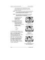
This manual pertains to:
North American approved instruments with Serial Number prefix "F" and "G"
Australian approved instruments with Serial Number prefix "A"
EN approved instruments with Serial Number prefix "A".
© MINE SAFETY APPLIANCES COMPANY 2005 - All Rights Reserved
Manufactured by
MSA INSTRUMENT DIVISION
P.O. Box 427, Pittsburgh, Pennsylvania 15230
(L) Rev 11
710436
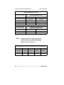
MSA Portable Instrument Warranty
1.
WarrantyITEM
WARRANTY PERIOD
Chassis and electronics
Lifetime (MSA will support product
for five years after production ends)
All sensors, unless otherwise specified
Two years
Pump and drive unit
Two years
Rechargeable batteries
Two years
This warranty does not cover filters, fuses, etc. Certain other
accessories not specifically listed here may have different warranty
periods. This warranty is valid only if the product is maintained and
u s ed i n ac c o rd a nc e wit h Sel le r’s i ns tr u ct ion s an d/o r
recommendations. The Seller shall be released from all obligations
under this warranty in the event repairs or modifications are made by
persons other than its own or authorized service personnel or if the
warranty claim results from physical abuse or misuse of the product.
No agent, employee or representative of the Seller has any authority
to bind the Seller to any affirmation, representation or warranty
concerning this product. Seller makes no warranty concerning
components or accessories not manufactured by the Seller, but will
pass on to the Purchaser all warranties of manufacturers of such
components. THIS WARRANTY IS IN LIEU OF ALL OTHER
WARRANTIES, EXPRESSED, IMPLIED OR STATUTORY, AND IS
STRICTLY LIMITED TO THE TERMS HEREOF. SELLER
SPECIFICALLY DISCLAIMS ANY WARRANTY OF
MERCHANTABILITY OR OF FITNESS FOR A PARTICULAR
PURPOSE.
2.
Exclusive Remedy- It is expressly agreed that Purchaser’s sole and
exclusive remedy for breach of the above warranty, for any tortious
conduct of Seller, or for any other cause of action, shall be the repair
and/or replacement at Seller’s option, of any equipment or parts thereof,
which after examination by Seller is proven to be defective. Replacement
equipment and/or parts will be provided at no cost to Purchaser, F.O.B.
Seller’s Plant. Failure of Seller to successfully repair any nonconforming
product shall not cause the remedy established hereby to fail of its
essential purpose.
3.
Exclusion of Consequential Damages- Purchaser specifically
understands and agrees that under no circumstances will seller be liable
to purchaser for economic, special, incidental or consequential damages
or losses of any kind whatsoever, including but not limited to, loss of
anticipated profits and any other loss caused by reason of nonoperation
of the goods. This exclusion is applicable to claims for breach of warranty,
tortious conduct or any other cause of action against seller.
Instruction Manual
Table of Contents
Table of Contents
General Description . . . . . . . . . . . . . . . . . . . . . . . . . . . . . . . .
"WARNINGS . . . . . . . . . . . . . . . . . . . . . . . . . . . . . . . . . .
"CAUTIONS. . . . . . . . . . . . . . . . . . . . . . . . . . . . . . . . . . .
Certifications . . . . . . . . . . . . . . . . . . . . . . . . . . . . . . . . . . . . . .
Electromagnetic Interference . . . . . . . . . . . . . . . . . . . . . .
General Limitations . . . . . . . . . . . . . . . . . . . . . . . . . . . . . . . . .
Preparation . . . . . . . . . . . . . . . . . . . . . . . . . . . . . . . . . . . . . . .
Battery Pack Installation . . . . . . . . . . . . . . . . . . . . . . . . .
Figure 2-1. Battery Pack Installation . . . . . . . . . . . . .
Figure 2-2. Serial Number
and Software Version . . . . . . . . . . . . . . . . . . . . . . . . .
Figure 2-3. Self Test. . . . . . . . . . . . . . . . . . . . . . . . . .
Figure 2-4. Setup Now - No/Yes? . . . . . . . . . . . . . . .
Figure 2-5. Alternate Language Option . . . . . . . . . . .
Figure 2-6. Scrolling through the Language Options
Figure 2-7. Operating Beep - No/Yes? . . . . . . . . . . .
Figure 2-8. Peak STEL TWA? . . . . . . . . . . . . . . . . . .
Figure 2-9. Time and Date Set . . . . . . . . . . . . . . . . .
Figure 2-10. Time Set . . . . . . . . . . . . . . . . . . . . . . . .
Figure 2-11. Time Set Complete . . . . . . . . . . . . . . . .
Figure 2-12. Date Set. . . . . . . . . . . . . . . . . . . . . . . . .
Figure 2-13. Day, Month, Year . . . . . . . . . . . . . . . . .
Turning ON the FiveStar Alarm. . . . . . . . . . . . . . . . . . . .
Figure 2-14. Date Set Complete . . . . . . . . . . . . . . . .
Figure 2-15. Show Alarms? . . . . . . . . . . . . . . . . . . . .
Figure 2-16. Setup Complete . . . . . . . . . . . . . . . . . . .
Fresh Air Set Up Option
(for automatic zero adjustment of the FiveStar Alarm sensors) . . . .
"WARNING . . . . . . . . . . . . . . . . . . . . . . . . . . . . . . . . . . .
Figure 2-17. Units Measured . . . . . . . . . . . . . . . . . . .
Figure 2-18. Gases Measured . . . . . . . . . . . . . . . . . .
To Proceed With Fresh Air Setup: . . . . . . . . . . . . . . . . .
To Bypass The Fresh Air Set Up: . . . . . . . . . . . . . . . . .
Figure 2-19. Fresh Air Set-up . . . . . . . . . . . . . . . . . .
FiveStar Alarm
1-1
1-1
1-4
1-4
1-4
1-5
2-1
2-1
2-1
2-2
2-2
2-2
2-2
2-3
2-3
2-3
2-4
2-4
2-4
2-5
2-5
2-6
2-6
2-6
2-6
2-7
2-7
2-7
2-7
2-8
2-8
2-8
TOC-1
Table of Contents
Instruction Manual
Figure 2-20. FAS Canceled/OK . . . . . . . . . . . . . . . . . 2-8
Using the FiveStar Alarm . . . . . . . . . . . . . . . . . . . . . . . . . . . . 2-9
Exposure Display . . . . . . . . . . . . . . . . . . . . . . . . . . . . . . . 2-9
Figure 2-21. Exposure Page. . . . . . . . . . . . . . . . . . . . 2-9
Battery Condition . . . . . . . . . . . . . . . . . . . . . . . . . . . . . . 2-10
Battery Conditions that can be displayed on the
Battery Display Page: . . . . . . . . . . . . . . . . . . . . . . . . . . 2-10
Figure 2-22. Gas Units . . . . . . . . . . . . . . . . . . . . . . . 2-10
Figure 2-23. Battery Condition . . . . . . . . . . . . . . . . . 2-10
Figure 2-24. Replaceable Battery Page . . . . . . . . . . 2-10
Approximate Voltage Readings for
Replaceable Battery Pack Alarms . . . . . . . . . . . . . . 2-11
" WARNING . . . . . . . . . . . . . . . . . . . . . . . . . . . . . . . . . 2-11
" WARNING . . . . . . . . . . . . . . . . . . . . . . . . . . . . . . . . . 2-11
" WARNING . . . . . . . . . . . . . . . . . . . . . . . . . . . . . . . . . 2-12
" CAUTION . . . . . . . . . . . . . . . . . . . . . . . . . . . . . . . . . . 2-12
" WARNING . . . . . . . . . . . . . . . . . . . . . . . . . . . . . . . . . 2-12
Time Display . . . . . . . . . . . . . . . . . . . . . . . . . . . . . . . . . . 2-12
Figure 2-25. Time Display. . . . . . . . . . . . . . . . . . . . . 2-12
Measuring Gas Concentrations . . . . . . . . . . . . . . . . . . . . . . 2-13
Combustible Gases (COMB) . . . . . . . . . . . . . . . . . . . . . 2-13
" WARNING . . . . . . . . . . . . . . . . . . . . . . . . . . . . . . . . . 2-13
Figure 2-26. Combustible Gas Alarm Flag . . . . . . . 2-13
Oxygen Measurements. . . . . . . . . . . . . . . . . . . . . . . . . . 2-14
" WARNING. . . . . . . . . . . . . . . . . . . . . . 2-14
Toxic Gas Measurement . . . . . . . . . . . . . . . . . . . . . . . . 2-14
Figure 2-27. Oxygen Alarm Flag . . . . . . . . . . . . . . . 2-14
" WARNING . . . . . . . . . . . . . . . . . . . . . . . . . . . . . . . . . 2-15
Calibration Check . . . . . . . . . . . . . . . . . . . . . . . . . . . . . . . . . 2-15
Figure 2-28. Metal Calibration Cap Installation
(Early Versions Only) . . . . . . . . . . . . . . . . . . . . . . . . 2-15
Figure 2-29. Snap Calibration Cap Installation . . . . 2-15
Options. . . . . . . . . . . . . . . . . . . . . . . . . . . . . . . . . . . . . . . . . . 2-16
Optional Displays . . . . . . . . . . . . . . . . . . . . . . . . . . . . . . 2-16
Peak Readings . . . . . . . . . . . . . . . . . . . . . . . . . . . . . . . . 2-16
To reset the Peak Readings:. . . . . . . . . . . . . . . . . . . . . 2-16
Figure 2-30. Peak Readings. . . . . . . . . . . . . . . . . . . 2-16
Figure 2-31. Reset Peak Readings . . . . . . . . . . . . . 2-16
TOC-2
FiveStar Alarm
Instruction Manual
Table of Contents
Short Term Exposure Limit (STEL). . . . . . . . . . . . . . . .
Figure 2-32. STEL Page . . . . . . . . . . . . . . . . . . . . .
Figure 2-33. STEL Alarm Flag . . . . . . . . . . . . . . . . .
" WARNING . . . . . . . . . . . . . . . . . . . . . . . . . . . . . . . . .
Time Weighted Average (TWA) . . . . . . . . . . . . . . . . . .
Figure 2-34. Reset TWA Page . . . . . . . . . . . . . . . .
" WARNING . . . . . . . . . . . . . . . . . . . . . . . . . . . . . . . . .
Datatagging Option . . . . . . . . . . . . . . . . . . . . . . . . . . . . . . . .
Setting a Tag . . . . . . . . . . . . . . . . . . . . . . . . . . . . . . . . .
Autocalibration. . . . . . . . . . . . . . . . . . . . . . . . . . . . . . . . . . . .
Figure 2-35. Setting Tag Page. . . . . . . . . . . . . . . . .
Figure 2-36. Last Data Tag Page . . . . . . . . . . . . . .
Figure 2-37. Editing Tag Page. . . . . . . . . . . . . . . . .
Figure 2-38. Recording Tag Page . . . . . . . . . . . . . .
Table 2-1. Autocalibration Allowable Sensors &
Required Calibration Cylinders . . . . . . . . . . . . . . . . .
Figure 2-39. Auto Cal? YES/NO . . . . . . . . . . . . . . .
Figure 2-40. Apply Cal Gas . . . . . . . . . . . . . . . . . . .
Figure 2-41. Example of a Combustible Gas Reading
Figure 2-42. Auto Cal Fail Show/OK . . . . . . . . . . . .
Figure 2-43. Example of
Expected Gas Values . . . . . . . . . . . . . . . . . . . . . . . .
Figure 2-44. Example of Expected Values with
OK/LOW/HIGH . . . . . . . . . . . . . . . . . . . . . . . . . . . . .
Turning OFF the FiveStar Alarm . . . . . . . . . . . . . . . . . . . . .
Battery Pack Removal . . . . . . . . . . . . . . . . . . . . . . . . . . . .
" CAUTION. . . . . . . . . . . . . . . . . . . . . . . . . . . . . . . . . .
Optional Sampling Equipment . . . . . . . . . . . . . . . . . . . . . . .
Figure 2-45. Power Down . . . . . . . . . . . . . . . . . . . .
Figure 2-46. Battery Pack Removal. . . . . . . . . . . . .
PulseCheckTM Pump Module . . . . . . . . . . . . . . . . . . . .
Temporary Pump Installation . . . . . . . . . . . . . . . . . . . . .
Permanent Pump Installation. . . . . . . . . . . . . . . . . . . . .
Figure 2-47. PulseCheck Pump Module . . . . . . . . .
Turn ON Instrument and Verify Proper Operation . . . .
" WARNING . . . . . . . . . . . . . . . . . . . . . . . . . . . . . . . . .
Figure 2-48. Pump Alarm . . . . . . . . . . . . . . . . . . . . .
"! CAUTION. . . . . . . . . . . . . . . . . . . . . . . . . . . . . . . . . .
FiveStar Alarm
2-17
2-17
2-17
2-18
2-18
2-18
2-19
2-19
2-20
2-20
2-20
2-20
2-20
2-20
2-21
2-21
2-21
2-21
2-22
2-22
2-22
2-23
2-23
2-23
2-23
2-23
2-23
2-24
2-24
2-24
2-24
2-25
2-25
2-25
2-26
TOC-3
Table of Contents
Instruction Manual
FiveStar Alarm Aspirator Assembly . . . . . . . . . . . . . . . .
"! WARNING . . . . . . . . . . . . . . . . . . . . . . . . . . . . . . . . .
" WARNING . . . . . . . . . . . . . . . . . . . . . . . . . . . . . . . . .
Attaching the Aspirator Assembly . . . . . . . . . . . . . . . . .
Operation and Use . . . . . . . . . . . . . . . . . . . . . . . . . . . . .
" CAUTION . . . . . . . . . . . . . . . . . . . . . . . . . . . . . . . . . .
Attaching Probe to Sampling Line . . . . . . . . . . . . . . . . .
Changing the Probe Filter . . . . . . . . . . . . . . . . . . . . . . .
Figure 2-49. Attaching Probe to Sample Line . . . . .
Figure 2-50. Changing the Probe Filter . . . . . . . . . .
Removing Sampling Equipment . . . . . . . . . . . . . . . . . . .
Keying Series Red/Series Green Battery Packs . . . . . . . . .
" CAUTION . . . . . . . . . . . . . . . . . . . . . . . . . . . . . . . . . .
Figure 2-51. Key for SERIES GREEN Battery Pack .
Recharging Ni-Cad and NiMH Battery Packs . . . . . . . . . .
Figure 2-52. Ni-Cad Charger (120V version shown) .
Recharge Times . . . . . . . . . . . . . . . . . . . . . . . . . . . .
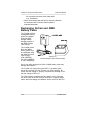
Replaceable Battery Pack Instructions. . . . . . . . . . . . . . . . .
" CAUTION . . . . . . . . . . . . . . . . . . . . . . . . . . . . . . . . . .
Figure 2-53. Battery and Fuse Location . . . . . . . . .
To Replace the Fuse . . . . . . . . . . . . . . . . . . . . . . . . . . .
2-26
2-26
2-27
2-27
2-27
2-28
2-28
2-28
2-28
2-28
2-29
2-29
2-29
2-29
2-30
2-30
2-31
2-31
2-32
2-32
2-33
Chapter 3
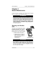
General Maintenance . . . . . . . . . . . . . . . . . . . . . . . . . . . . 3-1
"! WARNING . . . . . . . . . . . . . . . . . . . . . . . . . . . . . . . . . .
Cleaning and Routine Care . . . . . . . . . . . . . . . . . . . . . . . . . .
" CAUTION . . . . . . . . . . . . . . . . . . . . . . . . . . . . . . . . . . .
Figure 3-1. Sensor Cover Plate . . . . . . . . . . . . . . . . .
Storage . . . . . . . . . . . . . . . . . . . . . . . . . . . . . . . . . . . . . . . . . .
Storage for Models with Nitric Oxide (NO)
or Ammonia (NH3) Sensors . . . . . . . . . . . . . . . . . . . . . . .
"! WARNING . . . . . . . . . . . . . . . . . . . . . . . . . . . . . . . . . .
Shipment . . . . . . . . . . . . . . . . . . . . . . . . . . . . . . . . . . . . . . . . .
Checking the Pump and Aspirator Inlet Filter . . . . . . . . . . . .
Replacing the Filters. . . . . . . . . . . . . . . . . . . . . . . . . . . . .
Dust Filter . . . . . . . . . . . . . . . . . . . . . . . . . . . . . . . . . . . . .
Water Filter . . . . . . . . . . . . . . . . . . . . . . . . . . . . . . . . . . . .
Internal "Firewall" Filter - Pump Module . . . . . . . . . . . . .
TOC-4
3-1
3-1
3-1
3-1
3-2
3-2
3-2
3-2
3-3
3-3
3-3
3-4
3-4
FiveStar Alarm
Instruction Manual
Table of Contents
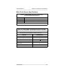
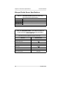
Instrument Specifications . . . . . . . . . . . . . . . . . . . . . . . . . . . .
Table 4-1. Instrument Specifications . . . . . . . . . . . . .
Measurement Methods . . . . . . . . . . . . . . . . . . . . . . . .
Capacity Reductions Expected for Batteries
at Colder Temperatures . . . . . . . . . . . . . . . . . . . . . . .
Approximate Battery Run Times . . . . . . . . . . . . . . . .
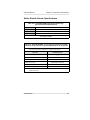
Combustible Gas Sensor Specifications . . . . . . . . . . . . .
Table 4-2. COMBUSTIBLE GAS - Typical
Performance Specifications . . . . . . . . . . . . . . . . . . . .
Table 4-3. COMBUSTIBLE GAS Cross Reference Factors for FiveStar
General-Purpose Calibration
Using Calibration Cylinder (P/N 478191),
(P/N 478192), (P/N 804769), or (P/N 804770)
Set to 58% LEL . . . . . . . . . . . . . . . . . . . . . . . . . . . . .
Oxygen Sensor Specifications. . . . . . . . . . . . . . . . . . . . .
Environment and Oxygen Sensor Readings . . . . . . . . .
Pressure Changes . . . . . . . . . . . . . . . . . . . . . . . . . . . . . .
Humidity Changes . . . . . . . . . . . . . . . . . . . . . . . . . . . . . .
Table 4-4. OXYGEN Typical Performance Specifications . . . . . . . . . . . . . .
Carbon Monoxide Sensor Specifications . . . . . . . . . . . .
Table 4-5. CARBON MONOXIDE
(appropriate models only) Typical Performance Specifications . . . . . . . . . . . . . .
Table 4-6. - CARBON MONOXIDE Cross Reference Factors
for FiveStar Calibration
Using Calibration Cylinder (P/N 478191)
or (P/N 804770) . . . . . . . . . . . . . . . . . . . . . . . . . . . . .
Hydrogen Sulfide Sensor Specifications . . . . . . . . . . . . .
Table 4-7. HYDROGEN SULFIDE
(appropriate models only) Typical Performance Specifications . . . . . . . . . . . . . .
Table 4-8. HYDROGEN SULFIDE Cross Reference Factors
for FiveStar Calibration Using Calibration Cylinder
(P/N 804769) or (P/N 804770) Set to 10 ppm H2S .
Nitric Oxide Sensor Specifications . . . . . . . . . . . . . . . . .
FiveStar Alarm
4-1
4-1
4-1
4-2
4-2
4-3
4-3
4-3
4-4
4-4
4-4
4-4
4-4
4-5
4-5
4-5
4-6
4-6
4-6
4-7
TOC-5
Table of Contents
Instruction Manual
Table 4-9. NITRIC OXIDE
(appropriate models only) - Typical Performance
Specifications . . . . . . . . . . . . . . . . . . . . . . . . . . . . . . . . 4-7
Table 4-10. NITRIC OXIDECross Reference Factors
for FiveStar Calibration
Using Calibration Cylinder (P/N 812144)
Set to 50 ppm NO . . . . . . . . . . . . . . . . . . . . . . . . . . . 4-7
Nitrogen Dioxide Sensor Specifications. . . . . . . . . . . . . . 4-8
Table 4-11. NITROGEN DIOXIDE
(appropriate models only) Typical Performance Specifications . . . . . . . . . . . . . . 4-8
Table 4-12. NITROGEN DIOXIDE Cross Reference Factors
for FiveStar Calibration
Using Calibration Cylinder (P/N 808977)
Set to 10 ppm NO2 . . . . . . . . . . . . . . . . . . . . . . . . . . . 4-8
Sulfur Dioxide Sensor Specifications . . . . . . . . . . . . . . . . 4-9
Table 4-13. SULFUR DIOXIDE
(appropriate models only) Typical Performance Specifications . . . . . . . . . . . . . . 4-9
Table 4-14. SULFUR DIOXIDE Cross Reference Factors
for FiveStar Calibration
Using Calibration Cylinder (P/N 808978)
Set to 10 ppm SO2 . . . . . . . . . . . . . . . . . . . . . . . . . . . 4-9
Ammonia Sensor Specifications. . . . . . . . . . . . . . . . . . . 4-10
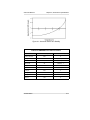
General Information . . . . . . . . . . . . . . . . . . . . . . . . . . . . 4-10
Zero Stability (FIGURE 4-1). . . . . . . . . . . . . . . . . . . . . . 4-10
Table 4-15. AMMONIA (appropriate models only)
Typical Performance Specifications . . . . . . . . . . . . . 4-10
Table 4-16. AMMONIA Cross Reference Factors . 4-11
Figure 4-1. Ammonia Sensor Zero Stability . . . . . . 4-11
Phosphine Sensor Specifications. . . . . . . . . . . . . . . . . . 4-12
Table 4-18. PHOSPHINE Cross Reference Factors
for FiveStar General-Purpose Calibration
Using Calibration Cylinder (P/N 478191),
(P/N 478192), (P/N 804769), or (P/N 804770)
Set to 58% LEL. . . . . . . . . . . . . . . . . . . . . . . . . . . . . 4-12
TOC-6
FiveStar Alarm
Instruction Manual
Table of Contents
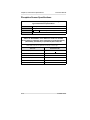
Table 4-17. PHOSPHINE
(appropriate models only)
Typical Performance Specifications . . . . . . . . . . . . .
Chlorine Sensor Specifications . . . . . . . . . . . . . . . . . . .
Special Instructions . . . . . . . . . . . . . . . . . . . . . . . . . . . .
Table 4-19. CHLORINE Typical Performance
Specifications. . . . . . . . . . . . . . . . . . . . . . . . . . . . . . .
Table 4-20. CHLORINE Cross Reference Factors
for FiveStar Calibration
Using Calibration Cylinder (P/N 806740)
Set to 10 ppm. . . . . . . . . . . . . . . . . . . . . . . . . . . . . .
" WARNING . . . . . . . . . . . . . . . . . . . . . . . . . . . . . . . . .
Chlorine Dioxide Sensor Specifications . . . . . . . . . . . .
Special Instructions . . . . . . . . . . . . . . . . . . . . . . . . . . . .
Table 4-22. CHLORINE DIOXIDE Cross Reference Factors
for FiveStar Calibration
Using Calibration Cylinder (P/N 806740)
Set to 4.95 ppm . . . . . . . . . . . . . . . . . . . . . . . . . . . .
Table 4-21. CHLORINE DIOXIDE
Typical Performance Specifications . . . . . . . . . . . . .
" WARNING . . . . . . . . . . . . . . . . . . . . . . . . . . . . . . . . .
4-12
4-13
4-13
4-13
4-13
4-14
4-15
4-15
4-15
4-15
4-16
Chapter 5
Accessories Parts List . . . . . . . . . . . . . . . . . . . . . . . . . . . 5-1
Table 5-1. Parts List . . . . . . . . . . . . . . . . . . . . . . . . . . 5-1
Table 5-2. Battery Pack and Charger Parts List. . . . 5-2
FiveStar Alarm
TOC-7
Instruction Manual
Chapter 1, Safety and General Limitations
Chapter 1
Safety and General Limitations
General Description
It is your responsibility to know how to use the
FiveStar Alarm. When used properly, the FiveStar Alarm will
alert you to the presence of combustible gases and vapors and
to atmospheres that are rich or deficient in oxygen. It will also
alert you to the presence of specific toxic gases if it is equipped
with sensors for those gases. These conditions are displayed
clearly and simultaneously on the face of the instrument.
" WARNINGS
• The FiveStar Alarm detects gases and vapors in air only. It
cannot measure combustible or toxic gases in:
- reducing atmospheres
- furnace stacks
- environments with inert gas backgrounds
• Do not use the FiveStar Alarm to measure combustible or toxic
gases when the amount of oxygen is:
- deficient
- enriched
• The FiveStar Alarm measures combustible gases and vapors. It
cannot measure the presence of combustible:
- airborne mists such as lubricating oils
- airborne dusts such as grain or coal dust
• The FiveStar Alarm contains sensors which detect specific toxic
gases. The instrument must be used to detect only those
specific gases. Other toxic hazards may be present; the
FiveStar Alarm is not intended to detect these other hazards.
FiveStar Alarm
1-1
Chapter 1, Safety and General Limitations
Instruction Manual
• Certain materials such as:
-
silicone
silicates
lead-containing compounds such as leaded gasoline
hydrogen sulfide (H2S) above 50 ppm for one minute
or any exposure over 200 ppm
tend to desensitize the combustible gas sensor, thereby
giving erroneously low readings. Calibration checks must be
made frequently if such materials are suspected to be
present in the tested atmosphere; otherwise, the instrument
may give false readings and endanger life or health.
• It is important that such information obtained with the instrument
be appraised by someone skilled or experienced in interpreting
the instrument reading intelligently in the light of environment,
industrial practice, and exposure. For example, an atmosphere
that is indicated as non-hazardous from the standpoint of fire
and explosion may, if inhaled, be toxic to workmen who are
exposed for some time. Similarly, a vessel which is safe before
work is started may be rendered explosive by future operations
(for example, stirring or handling bottom sludge in a petroleum
storage tank). The latter example indicates the need for
frequently repeated or continuous tests of questionable spaces
while work is in progress.
The instrument will respond to those concentrations of gases or
vapors which are presented to the sensors. If the combustible is
a high boiling point solvent and is tested at normal ambient
temperature, a relatively low vapor concentration will be
shown by the instrument. If the container holding such
solvents is subsequently heated as by welding and soldering, it
is to be expected that the vapor concentration will increase, and
thus the atmosphere of a vessel which was originally shown
to contain only a low concentration of vapors may be
rendered explosive.
If an attempt is made to use such instruments for testing
atmospheres contaminated with high boiling point solvents
where the questionable space is at a higher temperature than
the instrument, it can be anticipated that there may be some
condensation of the combustible vapors in the sampling line
and in the flow system of the instrument if used; as a
consequence, the instrument may indicate less than the true
1-2
FiveStar Alarm
Instruction Manual
Chapter 1, Safety and General Limitations
concentration of vapors. In general, combustible gases with
flash points above 100oF do not give off enough vapors, at
ambient temperatures, to be detected.
• When using a sampling pump and sample lines, the user must
wait the appropriate time for gas to be drawn through the
sample system to the sensors. Typical transport times are a
maximum of 0.3 seconds per foot of sample line.
• When sampling over liquids, the end of the sampling line must
not touch the surface of the liquid. Otherwise, liquids may enter
the instrument, block sample gas from entering the line, and
cause a false reading to occur. In addition, internal damage to
the instrument may result.
• Obstruction of the sensor holes in the instrument case causes
erroneous readings. These holes must be kept open at all
times. Do not use compressed air to clean the sensor holes;
excessive pressure at the face of the sensors could damage
them.
• Do not use MSA Lead Inhibitor Filters with this instrument. Loss
of sensitivity can result.
• Battery packs must be recharged in a non-hazardous location
free of combustible gases and vapors.
• A calibration check must be performed before each day’s use to
verify that the instrument is operating properly and readings are
accurate (or more frequently if the instrument is subjected to
significant physical shock or high levels of contaminants). If the
readings are not within the specified limits, the instrument must
be recalibrated before use. If no calibration check is performed,
inaccuracies in gas readings may not be detected. See the
FiveStar Alarm Technical Manual, Chapter 2, for calibration
check procedure.
• Use only genuine MSA replacement parts when performing any
maintenance procedures described in this manual. Substitution
of components can seriously impair instrument performance,
alter intrinsic safety characteristics, or void agency approvals.
• Repair or alteration of the FiveStar Alarm beyond procedures in
this manual or by anyone other than a person authorized by
MSA could cause the instrument to fail to perform properly.
FAILURE TO FOLLOW THE ABOVE WARNINGS CAN RESULT
IN SERIOUS PERSONAL INJURY OR DEATH.
FiveStar Alarm
1-3
Chapter 1, Safety and General Limitations
Instruction Manual
" CAUTIONS
• When sampling with accessory sampling lines, the shortest
possible length should be used to minimize the time needed to
obtain a valid reading.
• Acid gases, such as carbon dioxide, will shorten the service life
of the oxygen sensor.
• Do not push on the center of the oxygen or the toxic gas
sensor. Be especially careful when installing or replacing a
sensor. Damage to the sensor may result.
• This instrument is designed for use only with the battery
chargers listed in this manual. Use of other battery chargers
may result in damage to the battery pack and instrument.
• Before each day’s use, perform a calibration check (see
Chapter 2, "Calibration Check") and check the pump (if used)
for proper operation. (See Chapter 2, "Pump Operation.")
• Changes or modifications to this unit not expressly approved by
the party responsible for compliance could void the user’s
authority to operate the equipment.
• Dispose of used batteries in accordance with local health and
safety regulations.
• This instrument generates, uses and can radiate radio
frequency energy and can cause interference to radio
communications and television and radio reception. See
"Electromagnetic Interference" later in this chapter for
recommended interference reduction measures.
Certifications
Tests completed by MSA verify that the FiveStar Alarm meets
applicable industry and government standards (as of date of
manufacture), including those for Electromagnetic Interference.
Electromagnetic Interference
This equipment has been type tested and found to comply with
the limits for a Class A digital device, pursuant to Part 15 of the
FCC Rules. These limits are designed to provide a reasonable
degree of prevention against interference when the equipment is
operated in a commercial environment. This equipment generates,
uses, and can radiate radio frequency energy and, if not installed
and used in accordance with the instruction manual, may cause
1-4
FiveStar Alarm
Instruction Manual
Chapter 1, Safety and General Limitations
interference to radio communications. Operation of this equipment
in a residential area is likely to cause interference in which case
the user will be required to correct the interference at his own
expense.
This equipment was tested and found to comply with the limits
for a Class B digital device, pursuant to Part 15 of the FCC
Rules. These limits are designed to provide a reasonable degree
of prevention against harmful interference in a residential
installation.
Alarm levels are set at the factory and meet the most commonly
accepted standards; see Chapter 4 for details. Setpoints can be
changed to meet specific conditions.
This equipment generates, uses, and can radiate radio frequency
energy and, if not installed and used in accordance with the
instructions, may cause interference to radio communications.
However, there is no guarantee that interference will not occur in
a particular installation. If this equipment does cause
interference to radio or television reception, which can be
determined by turning the equipment OFF and ON, the user is
encouraged to try to correct the interference by one or more of
the following measures:
• Reorient or relocate the receiving antenna.
• Increase the separation between the equipment and receiver.
• Connect the equipment into an outlet on a circuit different from
that to which the receiver is connected.
• Consult the dealer or an experienced radio TV technician
for help.
This digital apparatus does not exceed the Class A limits for
radio noise emissions from digital apparatus set out in the Radio
Interference Regulations of the CRTC.
General Limitations
Combustible gases will burn or explode only when the fuel/air
mixture is within certain proportions. The minimum concentration
of a particular combustible gas in air which can be ignited is
defined as the Lower Explosive Limit (LEL). In some references,
the term Lower Flammability Limit (LFL) is used.
Combustible gas readings with an OVER alarm in the display
indicate an amount of gas which may be above the Lower
FiveStar Alarm
1-5
Chapter 1, Safety and General Limitations
Instruction Manual
Explosive Limit (LEL) or above 5% methane (CH4) by volume. In
such cases the instrument’s lockalarm feature activates,
preventing ambiguous readings which could occur above these
concentrations. (See Chapter 4 for limits.)
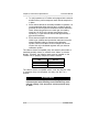
Instruments with Pumps or Aspirator Assemblies
If using a FiveStar instrument with a sampling pump or aspirator
bulb assembly, perform a blocked flow test before each day’s
use. When performing the test, the appropriate indication must
occur when blocking the flow. If the indication does not occur,
check the instrument flow system for leaks.
Once the leak condition is corrected, perform the blocked flow
test again to verify proper operation before using the instrument.
Refer to the applicable section in this instruction manual for
additional information.
WARNING
Perform a blocked flow test before each day’s use. Failure
to perform a blocked flow test can result in the user being
unaware of the presence of gas.
Do not use the instrument unless the blocked flow indications
occur when performing the blocked flow test. Lack of a
blocked flow indication is a sign that a leak exists and the
sample may not be drawn to the sensors, which could cause
a false reading.
Failure to follow the above can result in serious personal
injury or death.
Instruments with Pumps and Electronic Flow
Indicators
With the pump running, block the sample line inlet or probe inlet.
• The blocked flow flag on the display must illuminate and an
audible alarm must sound.
Instruments with Aspirator Bulbs
With the aspirator bulb squeezed, block the sample inlet or probe
inlet.
• The bulb must not inflate.
1-6
FiveStar Alarm
Instruction Manual
Chapter 1, Safety and General Limitations
• Please note that some instruments with electronic flow
indicators can have optional aspirator bulb accessories.
• The electronic flow indicators are not intended to activate when
the aspirator is attached.
If there are questions regarding this information, please contact
MSA Customer Service at:
1-800-MSA-2222
FiveStar Alarm
1-7
Instruction Manual
Chapter 2, Using the FiveStar Alarm
Chapter 2
Using the FiveStar Alarm
It is your responsibility to know how to use the FiveStar
Alarm. When used properly, the FiveStar Alarm will alert you to
the presence of combustible gases and vapors and to
atmospheres that are rich or deficient in oxygen. It will also alert
you to the presence of specific toxic gases if it is equipped with
sensors for those gases. These conditions are displayed clearly
and simultaneously on the face of the instrument.
Alarm levels are set at the factory and meet the most commonly
accepted standards; see Chapter 2 of the FiveStar Alarm
Technical Manual for details. Setpoints can be changed to meet
specific conditions.
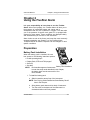
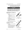
Preparation
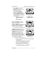
Battery Pack Installation
When the battery pack is installed, the user
has access to the following instrument options:
• Enable operating beep?
• Display Peak, STEL and TWA pages?
• Set time?
Figure 2-1.
• Set date?
Battery Pack Installation
NOTE: For Australian approved instruments:
to enter the setup mode described in this Chapter,
the battery pack must be removed for 10 or
more seconds.
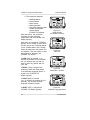
1. To install the battery pack:
a. Slide it toward the sensor face of the instrument.
NOTE: See "Keying Series Red/Series Green Battery Packs"
later in this Chapter.
b. Swing battery pack down and into body of instrument.
c.
Turn the screw on the bottom of the instrument in a
clockwise direction until firmly seated.
FiveStar Alarm
2-1
Chapter 2, Using the FiveStar Alarm
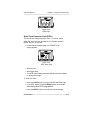
2. The instrument responds:
• backlight flashes
• screen flashes
• alarm sounds
• alarm lights flash
• instrument electronic serial
number and software
version display
(FIGURE 2-2) appears.
After this screen, the instrument
self-tests all major electronic
components and the (FIGURE 2-3)
display appears.
Instruction Manual
Figure 2-2.
Serial Number
and Software Version
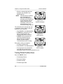
After tests are completed, if ERROR
appears on the screen and the alarm
sounds, refer to the Technical Manual
for the FiveStar Alarm (P/N 710440).
When the electronics test passes, the
unit inquires if the user wants to enter
Setup Mode by displaying the
(FIGURE 2-4) screen.
Figure 2-3.
Self Test
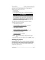
If PAGE (NO) is pressed, or no
buttons are pressed for five seconds,
the unit assumes the user did not
want to reset any options and unit
turns ON.
If RESET (YES) is pressed, the
instrument enters the Setup Mode.
If the Alternate Language Option is
enabled, the (FIGURE 2-5)
display appears.
Figure 2-4.
Setup Now - No/Yes?
If PAGE (SKIP) is pressed
(or if no buttons are pressed for five
seconds), the currently selected
language remains the same.
If RESET (SET) is pressed the
(FIGURE 2-6) display appears.
2-2
Figure 2-5.
Alternate Language Option
FiveStar Alarm
Instruction Manual
Chapter 2, Using the FiveStar Alarm
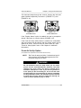
• Press PAGE (UP arrows) or
RESET (DOWN arrows) to scroll
through the languages.
• Once the desired language
displays, press ON/OFF (OK).
• If a new language is selected, the
instrument prompts the user to
choose to display the combustible
gas readings as:
• percent Lower Explosive
Limit (LEL) Pentane
OR
• percent Methane.
Figure 2-6.
Scrolling through the
Language Options
Pressing the PAGE (LEL) button
causes the combustible readings to
display as 0-100% LEL.
Pressing the RESET (YES) button causes
the instrument to display combustible
readings as direct 0-5% Methane.
• The (FIGURE 2-7) display appears.
Figure 2-7.
Operating Beep - No/Yes?
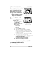
If PAGE (NO) is pressed, or no
buttons are pressed for five seconds,
the operating beep will be disabled.
If RESET (YES) is pressed, the
operating beep is enabled and the
instrument alarm sounds once every 30
seconds to indicate that the FiveStar
Alarm is turned ON. This beep does not
occur if YES is not selected.
• The (FIGURE 2-8) display appears.
Figure 2-8.
Peak STEL TWA?
• If YES is selected, the PEAK STEL TWA pages appear.
• If NO is selected,
the PEAK STEL TWA pages do not appear.
• If no button is pressed the unit maintains
the previous setting for these pages.
• The display moves to the "Set Time" page.
• The (FIGURE 2-9) display now appears.
FiveStar Alarm
2-3
Chapter 2, Using the FiveStar Alarm
Instruction Manual
Figure 2-9.
Time and Date Set
To cancel Time Set, press PAGE (SKIP) button or wait five seconds.
To set the time, press the RESET (YES) button.
• The (FIGURE 2-10) display appears.
Figure 2-10.
Time Set
• The hour flashes.
• Press the PAGE button to lower the hours
(19:05 is 7:05 P.M.).
• Press RESET to raise the hours.
• Press the ON/OFF button to accept the new number.
• The minutes now flash.
• Adjust as needed.
• Press the ON/OFF button to accept the reading.
• The (FIGURE 2-11) display appears.
Figure 2-11.
Time Set Complete
2-4
FiveStar Alarm
Instruction Manual
Chapter 2, Using the FiveStar Alarm
• The (FIGURE 2-12) display appears.
Figure 2-12.
Date Set
To cancel the date set, press the PAGE (SKIP) button or wait
five seconds.
To set the time, press the RESET (YES) button and the
(FIGURE 2-13) display appears.
Figure 2-13.
Day, Month, Year
• The Year is underlined.
• Press the PAGE button to lower the year.
• Press RESET to raise the year.
• Press ON/OFF to accept the year setting and move on.
• The month is now underlined.
• Press the PAGE button to lower the month.
• Press RESET to raise the month.
• Press ON/OFF to accept the month setting and move on.
• The day is now underlined.
• Press the PAGE button to lower the day.
• Press RESET to raise the day.
• Press ON/OFF to accept the day setting and move on.
FiveStar Alarm
2-5
Chapter 2, Using the FiveStar Alarm
• When the selected date has been
accepted, the (FIGURE 2-14)
display appears.
NOTE: The instrument is equipped
with a small battery to
retain time settings when
the battery pack is detached.
If your instrument does not
maintain the proper time
consistently, return it to your
nearest Service Center
to have this battery replaced.
Instruction Manual
Figure 2-14.
Date Set Complete
The instrument then prompts the user
to determine if they want to view the
instrument alarm setpoints.
• The (FIGURE 2-15) display appears.
• If PAGE (NO) is pressed (or if no
button is pressed within five
seconds), the setup is complete.
• If RESET (YES) is pressed, the
instrument steps through the
alarm screens [to view these
screens, see the FiveStar
Technical Manual (P/N 710440)].
Figure 2-15.
Show Alarms?
Once alarm viewing is complete:
• The alarm sounds briefly
• The (FIGURE 2-16) display appears.
Figure 2-16.
• The instrument now automatically
Setup Complete
turns ON and runs through the
following procedure for normal instrument turn-on.
Turning ON the FiveStar Alarm
Push the ON/OFF button.
• The backlight flashes
• The screen flashes
• The alarm sounds
• The alarm lights flash.
2-6
FiveStar Alarm
Instruction Manual
Chapter 2, Using the FiveStar Alarm
The instrument steps through two screens, showing the units and
gases installed respectively as shown in (FIGURE 2-17) and
(FIGURE 2-18).
Figure 2-17.
Units Measured
Figure 2-18.
Gases Measured
If the "Display Alarms" option is enabled, the user is prompted to
decide if they want to view the alarms (FIGURE 2-15).
If the Fresh Air Setup (FAS) feature is enabled, the combustible
and toxic sensors can be zeroed, and the oxygen sensor can be
spanned to 20.8%. FAS must only be used in fresh air. (See
"Fresh Air Setup Option" later in this Chapter for additional
information.)
Fresh Air Set Up Option
(for automatic zero adjustment of the FiveStar Alarm sensors)
NOTE:
The Fresh Air setup has limits. If a hazardous level of
gas is present, the FiveStar Alarm ignores the FAS
command and goes into alarm.
" WARNING
Do not activate the fresh air setup unless you are certain
you are in fresh, uncontaminated air; otherwise, inaccurate
readings can occur which can falsely indicate that a
hazardous atmosphere is safe. If you have any doubts as
to the quality of the surrounding air, do not use the fresh
air setup feature. Do not use the fresh air setup as a substitute
for daily calibration checks. The calibration check is required
to verify span accuracy. Failure to follow this warning can
result in serious personal injury or death.
FiveStar Alarm
2-7
Chapter 2, Using the FiveStar Alarm
Instruction Manual
Persons responsible for the use of the
FiveStar Alarm must determine
whether or not the Fresh Air Setup
option should be used. The user’s
abilities, training and normal work
practices must be considered when
making this decision.
• When the (FIGURE 2-19) display
appears, the FiveStar Alarm is
ready for its Fresh Air Set Up.
Figure 2-19.
Fresh Air Set-up
To Proceed With Fresh Air
Setup:
1. Press the RESET (YES) button;
the display reads:
ADJUSTING ZEROES
PLEASE WAIT
a. When the (FIGURE 2-20)
display appears:
• Alarm sounds
Figure 2-20.
FAS Canceled/OK
• Lights flash
1)
2)
3)
b.
Push the RESET (OK) button.
Make certain the FiveStar Alarm is in fresh air;
move to another location, if necessary. Allow the
FiveStar Alarm to warm up for a few minutes to allow
the sensors to stabilize.
Turn FiveStar Alarm OFF and then back ON again.
If the FiveStar Alarm cancels the Fresh
air Setup request again, calibration adjustments may be
required. Report to the person responsible for
FiveStar Alarm maintenance.
Do not use the instrument for protection.
When the Fresh Air Setup is completed:
• Instrument enters the Exposure display page,
displays gas readings, and is ready for use.
To Bypass The Fresh Air Set Up:
Press the PAGE (NO) button, or wait five seconds.
2-8
FiveStar Alarm
Instruction Manual
Chapter 2, Using the FiveStar Alarm
• Display enters Exposure page.
• Display begins to show gas readings.
• The instrument is ready for use.
If the sensors drift off of zero a few minutes after being turned
ON, move to fresh air; then, try the Fresh Air Setup again.
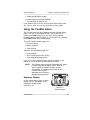
Using the FiveStar Alarm
The FiveStar Alarm has three standard and three optional display
pages. You can move sequentially from one to the next by
pressing the PAGE button. You can return to the standard
Exposure display page by waiting for 15 seconds or by pressing
the ON/OFF button from another page.
The three standard display pages are:
• Exposure display
• Battery condition
• Time and date.
The three optional display pages are:
• Peak readings
• Short Term Exposure Limit (STEL)
• Time Weighted Average (TWA).
If any one of these optional display pages is enabled, it will
appear on your instrument in the order shown above.
NOTE:
The FiveStar Alarm measures concentrations of gases
no matter what display page is shown. When an
alarm condition is reached, the alarm sounds
automatically. The measurements made by the
FiveStar Alarm are NOT
dependent upon a specific
display page being shown.
Exposure Display
In this normal display page, numbers
appear near the gas labels on the
instrument’s display panel
(FIGURE 2-21).
Figure 2-21.
Exposure Page
FiveStar Alarm
2-9
Chapter 2, Using the FiveStar Alarm
Instruction Manual
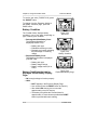
To see the gas units (FIGURE 2-22) press
the ON/OFF button.
To change from the Exposure display to
the Battery Condition page, press the
PAGE button.
Battery Condition
The FiveStar Alarm displays battery
condition in one of two ways, depending on
type of battery pack installed.
• Rechargeable NiCad Battery Pack The following information is
displayed(FIGURE 2-23):
• Battery pack type
• Estimated remaining run time
• Bargraph and number indicating
the percentage of remaining
charge.
• Replaceable Battery Pack The following information is displayed
(FIGURE 2-24):
• Battery pack type
• Battery charge voltage
• Battery voltage status (OK or
LOW).
Battery Conditions that can be
displayed on the Battery Display
Page:
Figure 2-22.
Gas Units
Figure 2-23.
Battery Condition
Figure 2-24.
Replaceable Battery Page
• OK: enough voltage to function properly
• LOW:
• BATT appears in the Exposure Display Page
• Horn sounds (Press the RESET button to silence it.)
• After initial LOW warning, the horn sounds
approximately every five minutes
• The battery will operate the FiveStar Alarm for
approximately 10 more minutes provided the RESET
button is pressed after each warning.
2-10
FiveStar Alarm
Instruction Manual
Chapter 2, Using the FiveStar Alarm
• The instrument will continue to operate until the power
is turned OFF or the battery condition is at BATTERY
SHUTDOWN level.
Approximate Voltage Readings for
Replaceable Battery Pack Alarms
WARNING
SHUT-DOWNS
3.3 VOLTS
3.1 VOLTS
• BATTERY SHUTDOWN: the battery is no longer able to
operate the instrument, and:
• BATTERY SHUTDOWN appears in place of the
Exposure Display Page. Horn sounds continuously and
cannot be reset.
• Alarm lights flash and the horn sounds intermittently.
• No other pages can be viewed.
• After approximately five minutes, the instrument shuts
down automatically.
" WARNING
When the Battery Shutdown condition sounds, stop using
the instrument. It cannot alert you of potential hazards
because it does not have enough power to operate properly.
You must:
1. Leave the area immediately.
2. Turn OFF the instrument if it is ON.
3. Report to the person responsible for maintenance.
Replace or recharge the battery pack.
If you do not follow this procedure, you could be injured
or killed.
" WARNING
For Replaceable Battery packs, replace batteries when the
"Battery Low" or "Battery Shutdown" alarms occur. When
replacing lithium or alkaline batteries, replace ALL batteries
with fresh ones at the same time. Do not mix battery types
or new and partially-discharged batteries. If the batteries
are improperly replaced or improperly mixed, the "Battery
Low" and "Battery Shutdown" alarms may fail to function,
which could result in serious personal injury or death.
FiveStar Alarm
2-11
Chapter 2, Using the FiveStar Alarm
Instruction Manual
" WARNING
Do not use rechargeable nickel cadmium batteries in
Replaceable Battery Packs. The Replaceable battery warning
and alarm setpoints are not optimized for nickel cadmium
batteries. The low battery warning and alarm could occur too
quickly to be noticed. If you do use nickel cadmium batteries
in the Replaceable battery pack you could be injured or killed.
NOTE:
The FiveStar unit recognizes the type of battery pack
(rechargeable nickel cadmium or replaceable
alkaline) is attached and automatically adjusts the
low battery warning and alarm setpoints.
" CAUTION
During "Battery Low" condition, prepare to exit the work area
as the instrument could go into "Battery Shutdown" at any
time, resulting in loss of sensor function. Depending on the
age of the batteries, ambient temperature and other conditions,
the FiveStar Alarm "Battery Low" and "Battery Shutdown" times
could be shorter than anticipated.
" WARNING
Recharge or replace the batteries when the "Battery Low" or
"Battery Shutdown" conditions occur.
Do not reuse a Ni-cad battery without recharging, even if
the battery regains some charge after a period of non-use.
When replacing Lithium or Alkaline batteries, replace ALL
batteries with fresh ones. Do not mix battery types or mix
new and partially-discharged batteries.
If batteries are not recharged or replaced or, if they are
mixed improperly, the "Battery Low" or "Battery Shutdown"
alarms may fail to function, which could result in serious
personal injury or death.
Time Display
Press the PAGE button
In the third standard display page, the time
and date are displayed. The time is displayed
in a 24-hour format. For example, "June 18
2-12
Figure 2-25.
Time Display
FiveStar Alarm
Instruction Manual
Chapter 2, Using the FiveStar Alarm
1995" would read as shown (FIGURE 2-25) at 7:06 p.m.
Measuring Gas Concentrations
Combustible Gases (COMB)
The FiveStar Alarm detects combustible gases in the atmosphere.
The Alarms sound when concentrations reach:
• Alarm setpoint, or
• 100% LEL (Lower Explosive Limit), or
• 5% CH4 (Methane by volume)
When the combustible gas indication
reaches the Alarm Setpoint:
• Alarm sounds
• Alarm lights flash
• Press the RESET button to
silence the alarm. (The alarm
will stay silent if the alarm
condition has cleared.)
• Concentration of gas flashes in the
display (FIGURE 2-26).
Figure 2-26.
Combustible Gas Alarm
Flag
When the combustible gas indication reaches 100% LEL or 5%
CH4 of the combustible gas:
• Alarm sounds
• Alarm lights flash
• This alarm cannot be reset with the RESET button.
The LockAlarm circuit locks the combustible gas reading and
alarm if the gas reading exceeds 100% LEL or 5% methane.
• OVER appears on the display.
" WARNING
If the OVER alarm condition is reached, you may be in a
life-threatening situation; there may be enough gas in the
atmosphere for an explosion to occur. In addition, any rapid
up-scale reading followed by a declining or erratic reading can
also be an indication that there is enough gas for an explosion.
If either of these indications occur, leave and move away from
FiveStar Alarm
2-13
Chapter 2, Using the FiveStar Alarm
Instruction Manual
the contaminated area immediately. Failure to follow this
warning can result in serious personal injury or death.
After moving to a safe, fresh-air environment, the alarm can be
reset by turning OFF the instrument and turning it ON again.
Oxygen Measurements
The FiveStar Alarm detects the amount of oxygen in the
atmosphere. There are two conditions which trigger the alarm:
• Too little oxygen (deficient)
• Too much oxygen (enriched)
At the Alarm Setpoint for either:
• Alarm sounds
• Alarm light flashes
• Concentration of gas flashes in the
display (FIGURE 2-27).
Figure 2-27.
Oxygen Alarm Flag
" WARNING
If the OXYGEN alarm condition is reached while using the
instrument as a personal or area monitor, leave the area
immediately; the ambient condition has reached a preset alarm
level. If using the instrument as an inspection device, do not
enter the area without proper protection. Failure to follow this
warning will cause exposure to a hazardous environment which
can result in serious personal injury or death.
Toxic Gas Measurement
The FiveStar Alarm detects certain toxic gases in the
atmosphere. Your instrument may have up to three toxic sensors.
Each of these sensors has a setpoint which causes an alarm if
the gas level goes above that setpoint. When this happens:
• Alarm sounds
• Alarm lights flash
• Concentration of gas flashes in the display.
2-14
FiveStar Alarm
Instruction Manual
Chapter 2, Using the FiveStar Alarm
" WARNING
If the TOXIC GAS alarm condition is reached while using the
instrument as a personal or area monitor, leave contaminated
area immediately; the ambient gas concentration has reached
a preset alarm level. If using the instrument as an inspection
device, do not enter area without proper protection. Failure
to follow this warning will cause over-exposure to toxic gases
which can result in serious personal injury or death.
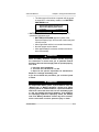
Calibration Check
This calibration check is very simple
and should only take one to five
minutes, depending on the number
and type of gases your FiveStar
Alarm is equipped to sense. Turn the
FiveStar Passport FiveStar Alarm ON
in clean fresh air, and verify that the
readings indicate no gas present.
1. Attach calibration cap to the
FiveStar Alarm, orienting the
inlet fitting to point toward the
battery pack:
2. Attach the calibration adapter
to the calibration cap.
3. Attach the regulator (supplied
with the calibration kit) to
the cylinder.
Figure 2-28.
Metal Calibration Cap Installation
(Early Versions Only)
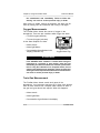
4. Connect the black tubing
supplied with the calibration kit
to the regulator.
5. Open the valve on the regulator,
and connect the other end of the
tubing to the inlet fitting.
The flow rate of the regulator is 0.25
lpm. Note the readings on the
FiveStar display; they should be within
the limits stated on the calibration
cylinder or limits determined by your
Figure 2-29.
company. (If necessary, change
Snap Calibration Cap Installation
FiveStar Alarm
2-15
Chapter 2, Using the FiveStar Alarm
Instruction Manual
cylinders to introduce other calibration gases.)
If the readings are not within these limits, the FiveStar Alarm
requires recalibration. See "Autocalibration" later in this Chapter
or, if autocalibration is not enabled, see the FiveStar Technical
Manual (P/N 710440), Chapter 2, for detailed manual calibration
instructions.
Options
Optional Displays
NOTE:
The following display pages appear only if enabled; see
the FiveStar Alarm Technical Manual for instructions.
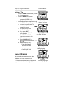
Press the PAGE button to move to:
Peak Readings
This shows the highest levels of
gas that the FiveStar Alarm
recorded since it was turned ON or
since the peak readings were reset
(FIGURE 2-30).
Figure 2-30.
Peak Readings
To reset the Peak Readings:
1. In Peak display, press the
RESET button.
• The (FIGURE 2-31)
display appears.
2. Press the RESET (YES)
button to reset peak readings
or press the PAGE (NO)
button or wait 15 seconds to
cancel.
Figure 2-31.
Reset Peak Readings
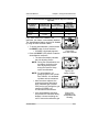
Press the PAGE button to move to
the (FIGURE 2-32) display.
2-16
FiveStar Alarm
Instruction Manual
Chapter 2, Using the FiveStar Alarm
Figure 2-32.
STEL Page
Short Term Exposure Limit (STEL)
This shows the average exposure over a 15 minute period.
When the amount of gas detected by the FiveStar Alarm is
greater than the STEL limit:
• On the Exposure display page, the (FIGURE 2-33)
display appears.
Figure 2-33.
STEL Alarm Flag
• Alarm sounds
• Alarm lights flash
• This STEL alarm display alternates with the exposure reading
on the exposure page.
To reset the alarm:
• Press the PAGE button four times to access the PEAK page
• In the STEL display, press the RESET button once and the
Acknowledge Reset STEL page appears.
• Press the RESET button a second time to acknowledge.
FiveStar Alarm
2-17
Chapter 2, Using the FiveStar Alarm
Instruction Manual
" WARNING
If the STEL alarm condition is reached while using the
instrument as a personal or area monitor, leave contaminated
area immediately; the ambient gas concentration has
reached the preset STEL alarm level. Failure to follow this
warning will cause over-exposure to toxic gases which can
result in serious personal injury or death.
The STEL alarm is calculated over a 15-minute exposure.
Calculation examples are as follows.
Assume the FiveStar Alarm has been running for at least 15 minutes.
• 15-minute exposure of 35 PPM:
(15 minutes x 35 PPM )
= 35 PPM
15 minutes
• 10-minute exposure of 35 PPM
5-minute exposure of 5 PPM:
(10 minutes x 35 PPM ) + (5 minutes x 5 PPM )
= 25 PPM
15 minutes
Assume the FiveStar Alarm was turned on five minutes ago.
• 5-minute exposure of 15 PPM:
(5 minutes x 15 PPM ) + (10 minutes x 0 PPM )
= 5 PPM
15 minutes
Press the PAGE button to move to:
Time Weighted Average (TWA)
TWA is the average exposure since the TWA reading was reset.
The TWA reading may be reset using the following procedure:
• Turn the FiveStar Alarm OFF for eight or
more hours or
• Press the PAGE button until the TWA
screen appears
• Press the RESET button; the
"Reset TWA" message appears
on the display.
• Press the RESET (YES) button.
2-18
Figure 2-34.
Reset TWA Page
FiveStar Alarm
Instruction Manual
Chapter 2, Using the FiveStar Alarm
When the amount of gas detected by the FiveStar Alarm is
greater than the eight-hour TWA limit:
• Alarm sounds
• Alarm lights flash
• On the Exposure display page, the TWA alarm flag displays.
" WARNING
If the TWA alarm condition is reached while using the
instrument as a personal or area monitor, leave contaminated
area immediately; the ambient gas concentration has
reached the preset TWA alarm level. Failure to follow this
warning will cause over-exposure to toxic gases which can
result in serious personal injury or death.
The TWA alarm is calculated over an eight-hour exposure.
Calculation examples are as follows:
• 1-hour exposure of 50 PPM:
(1 hour x 50 PPM) + (7 hours x 0 PPM )
= 6.25 PPM
8 hours
• 4-hour exposure of 50 PPM
4-hour exposure of 100 PPM:
(4 hours x 50 PPM) + (4 hours x 100 PPM )
= 75 PPM
8 hours
• 12-hour exposure of 100 PPM:
(12 hours x 100 PPM)
= 150 PPM
8 hours
NOTE:
The accumulated reading is always divided by eight
hours.
To reset the alarm: in the TWA display, press the RESET button.
Datatagging Option
Datatagging allows the user to save an alphanumeric designation
in the instrument’s session datalog. This data tag is saved with a
time stamp so it can then be related to the gas readings at that
time. This provides the user with an instrument location record
coupled with a date and time.
FiveStar Alarm
2-19
Chapter 2, Using the FiveStar Alarm
Instruction Manual
Setting a Tag
1. Press the PAGE button until the (FIGURE
2-35) screen appears:
2. Press the RESET (YES) button.
• A screen showing the last saved data
tag appears (FIGURE 2-36).
3. Press OK to accept the alphanumeric tag
or press EDIT to change the tag.
• If no button is pressed within 10
seconds, this data tag is
automatically stored.
• The display returns to the
Measure Gases Page.
a. If you press EDIT, a
screen similar to (FIGURE
2-37) appears.
b. Press PAGE or RESET
(up or down arrows) to edit
the first character.
c. Press ON/OFF (NEXT) to
proceed to the next character
in the tag.
d. Repeat Steps (b) and (c).
• Tag is automatically
recorded when last
character is entered.
• The (FIGURE 2-38)
screen appears:
Figure 2-35.
Setting Tag Page
Figure 2-36.
Last Data Tag Page
Figure 2-37.
Editing Tag Page
Autocalibration
The Autocalibration sequence resets the
instrument zeroes and adjusts the sensor
calibration for known concentration of
calibration gases. Autocalibration is standard
on FiveStar Alarms when factory-shipped with
any combination of the following sensors:
2-20
Figure 2-38.
Recording Tag Page
FiveStar Alarm
Instruction Manual
Chapter 2, Using the FiveStar Alarm
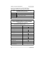
Table 2-1. Autocalibration Allowable Sensors & Required Calibration
Cylinders
AUTOCALIBRATION
ALLOWABLE
SENSORS
COMBUSTIBLE
OXYGEN
CARBON
MONOXIDE
HYDROGEN
SULFIDE
EXPECTED GAS
CONCENTRATION
THREE-GAS
CYLINDER
(MSA P/N 10010162)
FOUR-GAS
CYLINDER
(MSA P/N 804770
OR P/N 711058)
58%
15%
300 PPM
✔
✔
✔
✔
✔
✔
10 PPM
✔
If any other sensors are installed in the
instrument, the feature is automatically disabled.
The Autocalibration feature can also be disabled
by using the MSA FiveStar LINKTM.
• To access Autocalibration, press and hold
the RESET button for three seconds.
• (FIGURE 2-39) display appears.
• Press the RESET (YES) button to start the
Autocalibration sequence.
• The instrument display indicates
that it is adjusting zeroes.
NOTE: During the Autocalibration zero
procedure, the limits on the
zero adjustments present
during the Fresh Air Setup
option are eliminated.
NOTE: For autocalibration, all
gases must be in one cylinder.
See TABLE 2-1 for allowable
cylinders and concentrations.
• After zeroes are adjusted, the
instrument prompts the user to
apply calibration gas (FIGURE
2-40) and to cycle through the gas
readings (FIGURE 2-41)
one-at-a-time for 90 seconds.
• If the Autocalibration sequence
has passed, the instrument briefly
displays a screen reminding the
user to remove the calibration gas
FiveStar Alarm
Figure 2-39.
Auto Cal? YES/NO
Figure 2-40.
Apply Cal Gas
Figure 2-41.
Example of a
Combustible Gas
Reading
2-21
Chapter 2, Using the FiveStar Alarm
Instruction Manual
or the calibration cap (if a pump was not used).
• The instrument then automatically returns to the
Measure Gas mode.
NOTE: The autocalibration procedure adjusts the span value
for any sensors which pass the test. Sensors that
fail autocalibration are left unchanged.
NOTE: Since residual gas may be present, the instrument
may briefly go into an exposure alarm after the
calibration sequence is completed.
• If Autocalibration span
sequence fails, the
(FIGURE 2-42)
display appears.
• To view which sensor(s) failed,
press ON/OFF (SHOW) button.
• Instrument displays the
expected gas values
(FIGURE 2-43) and displays
if sensor reading
(FIGURE 2-44) was:
• OK
Figure 2-42.
Auto Cal Fail Show/OK
• LOW or
• HIGH.
If a sensor fails the calibration, this
does not necessarily indicate that the
sensor is no longer functional. In
order to ensure that proper
calibration gases were used (TABLE
2-1), the Autocalibration only
adjusts sensors that were initially
within 30% of the expected values.
If the sensor fails Autocalibration,
the calibration sequence given in
the FiveStar Technical Manual
(P/N 710440), Chapter 2, may be
used to manually adjust the sensor
to within specifications.
Figure 2-43.
Example of
Expected Gas Values
Figure 2-44.
Example of Expected Values
with OK/LOW/HIGH
2-22
FiveStar Alarm
Instruction Manual
Chapter 2, Using the FiveStar Alarm
Turning OFF
the FiveStar Alarm
Push and hold the ON/OFF button for
three seconds.
• The (FIGURE 2-45)
countdown appears.
Figure 2-45.
Power Down
Battery Pack Removal
1. Turn the power OFF by pressing
and holding the ON/OFF button for
five seconds.
• POWER OFF appears on the
display.
" CAUTION
Do not remove battery pack while
instrument is still ON. Failure to turn
instrument OFF prior to removing the
battery pack could damage the
instrument.
Figure 2-46.
2. Turn the battery mounting screw on
Battery Pack Removal
the back of the instrument in a
counterclockwise direction until the screw turns freely.
3. Pull out the battery pack by gripping it at the edge of the
battery pack case and pulling it away from the unit.
Optional Sampling Equipment
Sampling lines and related equipment permit samples of gas to
be taken from remote or inaccessible locations.
Sampling lines are five to 50 feet long and are made of a
synthetic material specifically compounded to resist absorption of
combustible and toxic vapors. Gases are drawn through the lines
to the FiveStar Alarm by a pump.
Using the shortest possible line reduces the time the pump must
run before valid samples and readings can be obtained.
FiveStar Alarm
2-23
Chapter 2, Using the FiveStar Alarm
Instruction Manual
TM
PulseCheck Pump Module
Through simple attachment, the PulseCheck
Pump Module allows you to change from
diffusion operation to pumped operation.
The pump may be attached temporarily (for
remote sampling) or permanently, depending
on your requirements.
• Prior to pump attachment, verify FiveStar
battery contacts are clean and
unobstructed.
• Inside the Pump Module and below the
Figure 2-47.
battery contacts, are two raised plastic
PulseCheck Pump Module
tabs which mate with two notches on the
FiveStar unit bottom, near the battery pack hold-down screw.
Battery and Pump Module contacts must meet to ensure
proper operation.
Temporary Pump Installation
1. Remove thumbscrews from pump module and store for
possible future use.
2. Bring the Pump Module toward the back of the instrument at
about a 45 degree angle.
3. Engage the tabs on the bottom of the pump with the slots in
the case.
4. Rock the pump housing down and snap the two sides of the
pump over the tabs on the sensor cover.
Permanent Pump Installation
To install the pump permanently on the FiveStar Alarm
1. Remove the two screws in the sensor cover nearest the
display head.
2. Bring the pump module toward the back of the instrument at
about a 45 degree angle.
3. Engage the tabs on the bottom of the pump with the slots in
the case.
4. Rock the pump housing down and snap the two sides of the
pump over the tabs on the sensor cover.
5. Finger-tighten thumbscrews into instrument.
2-24
FiveStar Alarm
Instruction Manual
Chapter 2, Using the FiveStar Alarm
• Do not over-tighten the screws as damage can occur.
Turn ON Instrument and Verify Proper Operation
1. Turn ON the FiveStar Unit.
• The pump motor will start fast, then slow down as the
instrument adjusts the power to run the pump.
2. Once the gas readings are
displayed, plug the free end of
the sampling line or probe. The
pump motor shuts down and an
alarm sounds. (The readings
on the display may change.)
When the pump inlet/sample
Figure 2-48.
line/probe is blocked, the
pump alarm must activate. If
Pump Alarm
the alarm does not activate,
check the pump/sample
line/probe for leaks; once the leak is fixed, recheck the pump
alarm by blocking the flow. Check the pump before each
day’s use.
" WARNING
Do not use the pump/sample line/probe unless the pump alarm
activates when the flow is blocked. Lack of an alarm is an
indication that a sample may not be drawn to the sensors,
which could cause inaccurate readings. Failure to follow the
above can result in serious personal injury or death.
3. Press the RESET button to reset the alarm and restart the
pump. During operation a pump alarm may occur when the:
• pump is attached or removed
• flow system is blocked
• pump unit is inoperative
• sample lines are attached or removed.
To clear the alarm:
• Correct the flow blockage (if necessary)
• Press the RESET button.
The pump will now restart.
FiveStar Alarm
2-25
Chapter 2, Using the FiveStar Alarm
Instruction Manual
NOTE: When the instrument is in a gas alarm, the pump
alarm may not display until after the gas alarm is
cleared.
"!CAUTION
Never let the end of the sampling line touch or go under
any liquid surface. If liquid is sucked into the instrument,
readings will be inaccurate and the instrument could be
damaged. We recommend the use of an MSA Sample Probe
(part no. 497600, 800332, 800333, or equivalent) containing
a special membrane filter, permeable to gas but impermeable
to water, to prevent such an occurrence.
FiveStar Alarm Aspirator Assembly
The FiveStar Alarm Aspirator Assembly is an accessory for use
with FiveStar Alarms. Through simple attachment, it allows you to
change from diffusion operation to pumped operation.
• Prior to Aspirator Assembly attachment, verify FiveStar battery
contacts are clean and unobstructed.
• Inside the Aspirator Assembly, below the battery contacts, are
two raised plastic tabs which mate with two notches on the
FiveStar unit bottom, near the battery pack hold-down screw.
Battery and Aspirator Assembly contacts must meet to ensure
proper operation.
"!WARNING
Once the Aspirator Assembly is no longer being used for sampling,
remove it and allow the Passport unit to sample in the diffusion
mode. Otherwise, if the Aspirator Assembly is in place and the
aspirator bulb is not actively being used, atmospheric samples
will not reach the sensors; inaccurate readings may occur, which
may cause serious personal injury or death.
Use this Aspirator Assembly to sample only the following
gases. Using the Aspirator Assembly to sample other gases
may result in inaccurate readings which may cause serious
personal injury or death.
Methane Hydrogen
2-26
Propane
Butane
Pentane
Ethane
Oxygen
Carbon
Monoxide
Hydrogen
Sulfide
FiveStar Alarm
Instruction Manual
Chapter 2, Using the FiveStar Alarm
" WARNING
Certain gases may react with the Aspirator Assembly; this
may cause lower than actual readings. If these gases are
suspected, re-verify readings in the diffusion mode by removing
the Aspirator Assembly or by using Pump Module (P/N 710790).
Attaching the Aspirator Assembly
1. Remove the two sensor lid screws located closest to the
display face.
• Store screws inside the Aspirator Assembly, on the white
manifold containing two recesses on each edge to
securely hold the screws.
2. Once screws are removed, align the Aspirator Assembly tabs
to sit inside the main body recesses by tilting the Aspirator
Assembly gently onto the back of the FiveStar unit.
• Ensure tabs engage notches; do not force connection as
damage can occur.
3. Gently rotate the Aspirator Assembly until the
manifold contacts the FiveStar unit sensor cover.
• Thumb screws align with holes left by the screws removed
in step 1.
4. Finger-tighten the screws to secure the Aspirator Assembly to
the FiveStar unit.
• Do not use tools or force the screws as damage can occur.
5. Attach sample lines (up to 25 feet long) and attach the probe.
Operation and Use
1. Block sample line or probe inlet and squeeze the aspirator bulb.
• With long sample line lengths (up to 25 feet), the bulb may
slowly inflate as a vacuum is drawn in the sample line;
squeeze the bulb one more time if necessary.
• The bulb should now remain deflated; if bulb inflates,
check for leaks and tighten as necessary.
2. Place the end of the probe at the point the sample is to be
taken.
3. Squeeze the bulb 10 times, allowing it to fully inflate
between squeezes.
• Note the readings.
FiveStar Alarm
2-27
Chapter 2, Using the FiveStar Alarm
Instruction Manual
NOTE: Due to pulsations introduced by the Aspirator Bulb
Assembly, instability of readings may occur. Before
noting the readings, allow readings to stabilize for
three or four seconds after the bulb is squeezed.
" CAUTION
Do not permit the end of the sampling line to touch or go
under any liquid surface. If liquid is sucked into the
instrument, readings will be inaccurate and the instrument
could be damaged. To prevent this, use Sample Probe (P/N
497600 or 800333) or an equivalent containing a special
membrane filter, permeable to gas but not to water.
Attaching Probe to Sampling Line
(FIGURE 2-49)
1. Grasp the probe handle by the top two
sections:
• the large section (cap) with the
MSA logo and
• the center section (base) with the
label.
Figure 2-49.
2. Unscrew lower section (guard) from Attaching Probe to Sample
the label section.
Line
3. Feed male end of the sample line
through the guard and screw into
the exposed connector ring on the
probe.
4. Screw the guard back onto the base.
Changing the Probe Filter
(FIGURE 2-50)
1. Grasp the probe handle by the base
and guard.
2. Push the cap section toward the other
two and turn clockwise (the spring
will push the sections apart).
3. Grasp and spin the wand clockwise
while pulling to disengage.
2-28
Figure 2-50.
Changing the Probe Filter
FiveStar Alarm
Instruction Manual
Chapter 2, Using the FiveStar Alarm
4. Remove the water trap filter and replace.
Removing Sampling Equipment
1. Turn OFF the FiveStar Alarm.
2. Unscrew the connector ring on the sampling line; remove
sampling line.
Keying Series Red/Series Green
Battery Packs
Instruments built after February, 1999 are designed to accept
keyed battery packs conforming to:
• North American standards (marked "SERIES GREEN") or to
• European/Australian standards (marked "SERIES RED").
Always match the battery pack to the corresponding instrument
by noting these SERIES GREEN and SERIES RED labels.
• Instruments built prior to February, 1999 conform to the North
American standards and should only be used with SERIES
GREEN battery packs.
" CAUTION
SERIES RED and SERIES GREEN battery packs are not
interchangeable; damage may occur to the instrument and/or
battery pack if the SERIES RED and SERIES GREEN battery
packs are interchanged.
• To use a new SERIES GREEN battery pack with a North
American standard
instrument built before
February, 1999:
1. To verify that the
instrument was built to
conform with
North American standard
s, ensure that it has an
approval label listing
MET and/or MSHA.
2. Remove the key in the
battery pack (FIGURE
2-51) by prying it out of
FiveStar Alarm
Figure 2-51.
Key for SERIES GREEN Battery Pack
2-29
Chapter 2, Using the FiveStar Alarm
Instruction Manual
the connector slot with a small, sharp object
(e.g., thumbtack).
• Never use a battery pack built prior to February 1999 with
an instrument built to conform with European or
Australian standards.
Recharging Ni-Cad and NiMH
Battery Packs
The FiveStar Ni-Cad
rechargeable battery
packs are charged
using the MSA
Omega® battery
charging system or
the MSA FiveStar
Fast Charger.
The FiveStar Alarm
NiCd and NiMH
battery packs must
be recharged using
the MSA Universal
Fast Charger
(P/N 10065552)
[Kit (P/N 10065553)
or (P/N 10065556)].
Figure 2-52.
Ni-Cad Charger (120V version shown)
Use of any other chargers for NiCd or NiMH battery packs may
damage the batteries.
The FiveStar unit should be turned OFF or the battery pack
should be removed from the FiveStar unit during charging. Be
certain that the charger is properly connected by checking to see
that the charger’s LED is lit.
The Fast Charger completes the fast charge cycle in less than
five hours after which the Charger switches to a topping charge
mode. After fast charge, the batteries will be more than 90% full.
2-30
FiveStar Alarm
Instruction Manual
Chapter 2, Using the FiveStar Alarm
Recharge Times
OMEGA CHARGER (NiCd Only)
FAST CHARGER
16 hours
WITHOUT TOPPING
WITH TOPPING
5 hours
7 hours
The battery pack may be charged when it is connected to the
FiveStar Alarm or when it is removed. If the battery pack is
connected to the FiveStar Alarm:
1. Turn OFF the instrument and insert it into the charge stand.
2. Insert the charger plug into the jack on the charge stand.
3. Plug the charger into a matching receptacle.
• The red light on the Omega Charger lights if the charger is
properly connected.
• The charge mode indicator light on the Fast Charger
turns red.
Replaceable Battery Pack Instructions
The FiveStar Alarm Replaceable Battery pack can be used as a
full-time battery pack or as a backup power source for all
Australian approved instruments and North American approved
instruments with hardware version "D1" or higher.
NOTE: To view the Hardware version, remove the instrument
battery pack. The Hardware/Software version is the
first two characters of the instrument serial number
located on the instrument under the battery.
The North American approved Replaceable Battery Pack is
provided with Energizer L91 AA lithium batteries.
• For the greatest run time or full-shift FiveStar Alarm operation, it
is recommended that you use these lithium batteries as
replacements.
• The Australian approved replaceable battery pack is provided
with Duracell MN1500 alkaline batteries. These are also
approved to operate the North American approved instrument.
To Replace the Batteries
1. Remove the battery pack from the instrument by loosening the
screw on the bottom-side of the instrument.
2. Turn the battery pack over and loosen the 1/4-turn fastener on
the bottom of the pack.
FiveStar Alarm
2-31
Chapter 2, Using the FiveStar Alarm
Instruction Manual
Figure 2-53.
Battery and Fuse Location
3. Open the pack and remove the old batteries. (FIGURE 2-53).
• Be sure to follow local regulations regarding
battery disposal.
4. Install the new batteries.
" CAUTION
When replacing the batteries in the pack, be sure to observe
the direction of the positive (+) battery terminals. If the
batteries are installed backwards and the battery pack is
installed on the instrument, the instrument will fail to operate
and the fuse in the battery pack may be blown.
5. Close the battery pack case and re-tighten the
1/4-turn fastener.
2-32
FiveStar Alarm
Instruction Manual
Chapter 2, Using the FiveStar Alarm
6. Install the battery pack on the instrument.
• If fresh batteries fail to properly initialize your instrument,
verify proper battery installation.
To Replace the Fuse
If the battery pack fuse has blown:
1. Remove and open the battery pack.
2. Locate and remove the blown fuse (FIGURE 2-53).
NOTE: Non-operational fuses do not provide a visual
indication. To ensure a fuse is operational, a
continuity check may be performed by using a
standard multimeter.
3. Locate the spare fuse on the other side of the battery
pack board.
4. Remove spare fuse from its holder and install it in the main
fuse holder.
5. Reassemble the battery pack, and reinstall it on the instrument.
FiveStar Alarm
2-33
Instruction Manual
Chapter 3, General Maintenance
Chapter 3
General Maintenance
As with all electronic equipment, the FiveStar Alarm will operate
only if it is cared for and maintained properly.
"!WARNING
Repair or alteration of the FiveStar Alarm beyond the procedures
described in this manual or by anyone other than a person
authorized by MSA could cause the instrument to fail to perform
properly. Use only genuine MSA replacement parts when
performing any maintenance procedures described in this
manual. Substitution of components can seriously impair
instrument performance, alter intrinsic safety characteristics or
avoid agency approvals.
Cleaning and Routine
Care
The case of the FiveStar Alarm should
be cleaned periodically with a soft cloth
dampened with water. If any sensor
holes on the front of the instrument are
blocked with dirt, they must be cleaned:
1. Remove sensor cover plate.
2. Clean the holes in the plate with
a paper clip, wire, or similar
device. The holes may also be
cleaned with oil-free
compressed air.
Figure 3-1.
Sensor Cover Plate
" CAUTION
Do not attempt to clean the sensor cover plate while it is in
place; otherwise, sensor damage can occur. The tops of
sensors are very fragile; do not touch or apply pressure to
the tops of any sensors. If a sensor is damaged it can cause
the unit to give false readings.
FiveStar Alarm
3-1
Chapter 3, General Maintenance
Instruction Manual
The sensor cover plate contains holes for five sensors. In
instruments with less than five sensors, some of these holes
are permanently blocked with special sealing membranes. Do
not puncture these membranes; otherwise, erroneous gas
readings can result.
Storage
Store your FiveStar Alarm in a safe, dry place when it is not in
use. The optimum storage temperature is between 23 and 104
degrees Fahrenheit (-5 and 40 degrees Celsius).
• The FiveStar Alarm with rechargeable battery packs can be
stored on charge indefinitely.
Storage for Models with Nitric Oxide (NO)
or Ammonia (NH3) Sensors
These models draw a small amount of power at all times (even
when turned OFF) in order to maintain a voltage on toxic gas
sensors and keep them ready for immediate use.
• When the FiveStar Alarm is stored for less than 20 days,
recharge the rechargeable battery pack or replace alkaline
batteries before storing.
• To store these models for more than 20 days, attach the unit to
a battery charger and charge with the proper MSA charger or
periodically replace alkaline batteries with fresh cells.
• If the instrument was stored without a charged battery attached,
attach the pack; then, allow the NO or NH3 sensor
to stabilize for 12 hours with the battery attached prior to
calibration and use.
"!WARNING
After storage, always recheck instrument calibration before use.
During storage, sensors may drift or become inoperative and
may not provide warnings of danger to the health and lives
of users.
Shipment
1. Remove battery pack before shipment. When returning the
FiveStar Alarm for repairs, disconnect the normally used
battery pack from the unit, and include it in the container.
3-2
FiveStar Alarm
Instruction Manual
Chapter 3, General Maintenance
2. Pack the FiveStar Alarm in its original shipping container with
suitable padding. If the original container is unavailable, an
equivalent container may be substituted if necessary. In
either case, seal the instrument in a plastic bag to protect it
from moisture. Protect the FiveStar Alarm from the rigors of
handling with sufficient padding. Damage due to improper
packaging or damage in shipment is not covered by the
instrument’s warranty.
Checking the Pump and Aspirator
Inlet Filter
The Pump Module and Aspirator Assembly contains a filtering
system to protect the pump from particles and water in the
sample air. If the filter becomes clogged, the sample flow may be
blocked or an extra load placed on the pump; therefore, check
the filter regularly.
The frequency of the checks should depend on the amount of
pump usage and the concentration of particles allowed to enter
the pump. In dirty applications it is suggested that the dust filter
be replaced every 200 hours. (See Filtering System Replacement
Parts List table at right.)
Replacing the Filters
NOTE:
Exercise care when replacing the external dust and
water filters to prevent dust and dirt around the filter
housing from entering the pump housing. Any dirt
sucked into the pump and drive unit may damage
pump operation.
Dust Filter
1. Remove screws from the clear filter housing on top of the
pump.
2. Remove the fibrous dust filter from the recess on the filter
housing.
3. Install the new dust filter into the recess.
4. Replace cover.
FiveStar Alarm
3-3
Chapter 3, General Maintenance
Instruction Manual
Water Filter
1. Remove the clear filter housing cover.
2. Carefully lift out the O-ring and white plastic disk resting in the
pump housing.
3. Replace the water filter, placing it carefully into the molded
recess on the pump housing.
NOTE: When replacing the filter, be sure to handle the new
one carefully, by the edges only, as it is easily torn.
Install the filters in the correct order.
4. Replace the O-ring, being sure to press gently down on top of
the water filter.
5. Replace cover.
Internal "Firewal l" Filter - Pump Module
The pump module is provided with an internal "firewall" filter to
form a final barrier against any dust that enters the pump
assembly when the external filters are replaced. This filter is
provided as a final safety precaution and should rarely, if ever,
need to be replaced.
1. Remove the four screws from the bottom of the pump housing.
2. Remove the back lid; note the tubing seating.
3. Carefully remove the old filter by pulling the tubing off the
barbed end fittings.
4. Install a new filter by pushing tubing over the end fittings.
5. Replace tubing in the pump housing. Seat tubing and pump
and drive unit in a similar manner as found when
disassembled.
6. Replace the housing screws. Gently rethread the screws,
guiding them into the same threads as initially cut.
3-4
FiveStar Alarm
Instruction Manual
Chapter 4, Performance Specifications
Chapter 4
Performance Specifications
Instrument Specifications
Table 4-1. Instrument Specifications
TEMPERATURE Normal
RANGE
Extended**
WARM-UP TIME
0 to 40o C
-20 to 50o C
With FAS
40 seconds; 45 seconds with pump
No FAS
20 seconds; 25 seconds with pump
PRESSURE
RANGE
80 kPa (560 mmHg) to 133 kPa (1010 mmHg)
*NOTE 1: Response times reported for diffusion usage:
When using a pump module and sample line, add time for the gas sample to be drawn
through the sample line. Typical transport times are:
10 feet
3 seconds
5 feet
7 seconds
50 feet
15 seconds
These should be added to the sensor response times reported in this Table.
**NOTE 2: Extended temperature range indicates that gas readings may vary slightly if
calibrated at room temperature. For optimal performance, it is recommended that the
instrument be calibrated at temperature of use.
Measurement Methods
COMBUSTIBLE
GAS
Catalytic Sensor
OXYGEN
Electrochemical Sensor
TOXIC GASES
Electrochemical Sensors
FiveStar Alarm
4-1
Chapter 4, Performance Specifications
Instruction Manual
Approximate Battery Run Times
NORTH AMERICAN
APPROVED INSTRUMENT
BATTERY TYPE
FIVESTAR Alarm OPERATING TIME
(WITHOUT DERATING/ AT 20oC)
WITHOUT PUMP
WITH PUMP
Ni Cad Standard
10-12 hours
8-10 hours
NiMH Heavy-duty
18-21 hours
14-16 hours
Lithium
11 hours
9 hours
Alkaline
7 hours
5 hours
EN AND AUSTRALIAN
APPROVED INSTRUMENT
BATTERY TYPE
FIVESTAR Alarm OPERATING TIME
(WITHOUT DERATING/ AT 20oC)
WITHOUT PUMP
WITH PUMP
Ni Cad Standard
8 hours
6 hours
NiMH Heavy-duty
16-20 hours
13-16 hours
NOTE:
In colder temperatures, battery output may be
severely reduced. The following table shows
capacity reductions expected for replaceable
batteries at these temperatures.
Capacity Reductions Expected for Batteries at Colder Temperatures
TEMPERATURE
NiCd
NiMH
AA ALKALINE
AA LITHIUM
70oF (21oC)
None
None
None
None
o
o
32 F (0 C)
10%
20%
25%
15%
14oF (-10oC)
20%
30%
60%
40%
4-2
FiveStar Alarm
Instruction Manual
Chapter 4, Performance Specifications
Combustible Gas Sensor Specifications
Table 4-2. COMBUSTIBLE GAS - Typical Performance Specifications
RANGE
RESOLUTION
REPRODUCIBILITY
RESPONSE TIME
0 to 100% LEL or
0 to 5% CH4
1% LEL or
0.1% CH4
3% LEL to 50% LEL reading
5% LEL to full scale or
0.2% CH4 to 2.5% Methane
0.3% CH4 to full scale
90% of final reading in 30 seconds (normal temperature range)*
*See TABLE 4-1, NOTE 1.
Table 4-3. COMBUSTIBLE GAS - Cross Reference Factors for FiveStar
General-Purpose Calibration Using Calibration Cylinder (P/N 478191),
(P/N 478192), (P/N 804769), or (P/N 804770) Set to 58% LEL
COMBUSTIBLE GAS
Acetone
Acetylene
Acrylonitrile1
Benzene
Butane
1,3 Butadiene
n-Butanol
Carbon Disulfide1
Cyclohexane
2,2 Dimethylbutane
2,3 Dimethylpentane
Ethane
Ethyl Acetate
Ethyl Alcohol
Ethylene
Formaldehyde2
Gasoline (unleaded)
Heptane
Hydrogen
n-Hexane
Isobutane
Isobutyl Acetate
Isopropyl Alcohol
Methane
Methanol
Methyl Isobutyl ketone
Methylcyclohexane
FiveStar Alarm
MULTIPLY %LEL
READING BY
1.1
0.7
0.8
1.1
1.0
0.9
1.8
2.2
1.1
1.2
1.2
0.7
1.2
0.8
0.7
0.5
1.3
1.1
0.6
1.3
0.9
1.5
1.1
0.5
0.6
1.1
1.1
COMBUSTIBLE GAS
Methyl Ethyl Ketone
Methyl Tertiary Butyl Ether
Mineral Spirits
iso-Octane
n-Pentane
Propane
Propylene
Styrene2
Tetrahydrofuran
Toluene
Vinyl Acetate
VM&P Naptha
0-Xylene
MULTIPLY %LEL
READING BY
1.1
1.0
1.1
1.1
1.0
0.8
0.8
1.9
0.9
1.1
0.9
1.6
1.2
RESPONSE NOTES:
1.
2.
3.
4.
5.
The compounds may reduce the sensitivity
of the combustible gas sensor by poisoning
or inhibiting the catalytic action.
These compounds may reduce the
sensitivity of the combustible gas sensor
by polymerizing on the catalytic surface.
For an instrument calibrated on Pentane,
multiply the displayed %LEL value by the
conversion factor above to get the true %LEL.
These conversion factors should be used
only if the combustible gas is known.
These conversion factors are typical for a
Portable Alarm. Individual units
may vary by + 25% from these values.
4-3
Chapter 4, Performance Specifications
Instruction Manual
Oxygen Sensor Specifications
Table 4-4. OXYGEN - Typical Performance Specifications
0 to 25% O2
RANGE
0.1% O2
RESOLUTION
REPRODUCIBILITY 0.5% O2, for 18 to 25% O2; 0.8% for less than 18%
RESPONSE TIME
30 seconds (normal temperature range)*
3 minutes (extended temperature range)
*See TABLE 4-1, NOTE 1.
90% of final reading
Environment and Oxygen Sensor Readings
A number of environmental factors may affect the oxygen sensor
readings, including changes in pressure, humidity and
temperature. Pressure and humidity changes affect the amount of
oxygen actually present in the atmosphere.
Pressure Changes
The FiveStar Alarm has a built-in pressure sensor to rapidly
compensate for ambient pressure changes in the area of
instrument operation. If pressure changes rapidly (e.g., stepping
through airlock) the oxygen sensor reading may temporarily shift,
and possibly cause the detector to go into alarm. Allow up to 30
seconds for the pressure sensor to update the oxygen sensor
reading; then, reset any alarms. While the percentage of oxygen
may remain at or near 20.8%, the total amount of oxygen present
in the atmosphere available for respiration may become a hazard
if the overall pressure is reduced to a significant degree.
Humidity Changes
If humidity changes to any significant degree (e.g., going from a
dry, air conditioned environment to outdoor, moisture laden air),
oxygen levels can change up to 0.5%. This is due to water vapor
in the air displacing oxygen, thus reducing oxygen readings as
humidity increases. The oxygen sensor has a special filter to
reduce the affects of humidity changes on oxygen readings. This
effect will not be noticed immediately, but slowly impacts oxygen
readings over several hours.
Temperature Changes
The oxygen sensor has built-in temperature compensation.
However, if temperature shifts dramatically, the oxygen sensor
reading may shift. Zero the instrument to within 30oC of the
temperature-of-use for the least effect.
4-4
FiveStar Alarm
Instruction Manual
Chapter 4, Performance Specifications
Carbon Monoxide Sensor Specifications
Table 4-5. CARBON MONOXIDE (appropriate models only) Typical Performance Specifications
RANGE
2000 ppm CO
RESOLUTION
1 ppm CO
REPRODUCIBILITY +2 ppm CO or 10% of reading, whichever is greater
RESPONSE TIME
90% of final reading in 30 seconds (normal temperature range)
Table 4-6. - CARBON MONOXIDE - Cross Reference Factors for
FiveStar Calibration Using Calibration Cylinder (P/N 478191)
or (P/N 804770)
NOTE:
Data is presented as the indicated output in ppm,
which would result from the application of 100 ppm of the test gas.
TEST GAS (100 PPM)
EQUIVALENT PPM
Carbon Monoxide (CO)
100 +9
Hydrogen Sulfide (H2S)
1 +6
Sulfur Dioxide (SO2)
0 +1
Nitrogen Dioxide (NO2)
2 +6
Nitric Oxide (NO)
70 +10
Chlorine (Cl2)
1 +8
Ammonia (NH3)
2 +4
Hydrogen Chloride (HCl)
3 +2
Ethylene (C2H4)
80 +9
Hydrogen Cyanide (HCN)
0 +1
Methane (CH4)
0 +0
Ethanol (EtOH)
4 +5
Hydrogen (H2)
70 +26
Chlorine Dioxide (ClO2)
NOTE:
0
Unsaturated hydrocarbons, such as ethylene, will have a significant positive reaction
with the CO sensors
FiveStar Alarm
4-5
Chapter 4, Performance Specifications
Instruction Manual
Hydrogen Sulfide Sensor Specifications
Table 4-7. HYDROGEN SULFIDE (appropriate models only) Typical Performance Specifications
RANGE
500 ppm H2S (200 ppm before August of 1999)
RESOLUTION
1 ppm H2S
+2 ppm H2S or
REPRODUCIBILITY 10%
of reading, whichever is greater
RESPONSE TIME
90% of final reading in 30 seconds* (normal temperature range)
*See TABLE 4-1, NOTE 1.
Table 4-8. HYDROGEN SULFIDE - Cross Reference Factors for
FiveStar Calibration Using Calibration Cylinder (P/N 804769)
or (P/N 804770) Set to 10 ppm H2S
NOTE:
Data is presented as the indicated output in ppm,
which would result from the application of 100 ppm of the test gas.
TEST GAS (100 PPM)
Hydrogen Sulfide (H2S)
EQUIVALENT PPM
100 +10
Ethylene (C2H4)
0 +0
Methane (CH4)
0 +0
Hydrogen (H2)
0 +0
Ammonia (NH3)
0 +0
Chlorine (Cl2)
0 +0
Nitrogen Dioxide (NO2)
-20 +2
Nitric Oxide (NO)
1 +1
Carbon Monoxide (CO)
0 +0
Hydrogen Chloride (HCl)
0 +0
Hydrogen Cyanide (HCN)
1 +1
Sulfur Dioxide (SO2)
10 +3
Ethanol (EtOH)
0 +0
Toluene
0 +0
Chlorine Dioxide (ClO2)
4-6
0
FiveStar Alarm
Instruction Manual
Chapter 4, Performance Specifications
Nitric Oxide Sensor Specifications
Table 4-9. NITRIC OXIDE (appropriate models only) Typical Performance Specifications
RANGE
100 ppm
RESOLUTION
1 ppm
REPRODUCIBILITY +2 ppm or +10% of reading, whichever is greater
RESPONSE TIME
25 seconds*
*See TABLE 4-1, NOTE 1.
Table 4-10. NITRIC OXIDE- Cross Reference Factors for FiveStar
Calibration Using Calibration Cylinder (P/N 812144) Set to 50 ppm NO
NOTE:
Data is presented as the indicated output in ppm,
which would result from the application of 100 ppm of the test gas.
TEST GAS
EQUIVALENT PPM
Carbon Monoxide (CO)
0
Hydrogen Sulfide (H2S)
1
Nitrogen Dioxide (NO2)
30 +5
Sulfur Dioxide (SO2)
0
Ammonia (NH3)
0
Carbon Dioxide (CO2)
0
Chlorine Dioxide (ClO2)
FiveStar Alarm
75
4-7
Chapter 4, Performance Specifications
Instruction Manual
Nitrogen Dioxide Sensor Specifications
Table 4-11. NITROGEN DIOXIDE (appropriate models only) Typical Performance Specifications
RANGE
100 ppm
RESOLUTION
0.5 ppm
REPRODUCIBILITY +2 ppm or +10% of reading, whichever is greater
RESPONSE TIME
50 seconds*
*See TABLE 4-1, NOTE 1.
Table 4-12. NITROGEN DIOXIDE - Cross Reference Factors for
FiveStar Calibration Using Calibration Cylinder (P/N 808977)
Set to 10 ppm NO2
NOTE:
Data is presented as the indicated output in ppm,
which would result from the application of 100 ppm of the test gas.
TEST GAS
EQUIVALENT PPM
Carbon Monoxide (CO)
< -5
Hydrogen Sulfide (H2S)
-8 +2
Nitric Oxide (NO)
0
Sulfur Dioxide (SO2)
0
Chlorine (Cl2)
-100 +15
Ammonia (NH3)
0
Carbon Dioxide (CO2)
0
Chlorine Dioxide (ClO2)
4-8
150 (over)
FiveStar Alarm
Instruction Manual
Chapter 4, Performance Specifications
Sulfur Dioxide Sensor Specifications
Table 4-13. SULFUR DIOXIDE (appropriate models only) Typical Performance Specifications
RANGE
100 ppm
RESOLUTION
0.5 ppm
REPRODUCIBILITY +2 ppm or +10% of reading, whichever is greater
RESPONSE TIME
50 seconds*
*See TABLE 4-1, NOTE 1.
Table 4-14. SULFUR DIOXIDE - Cross Reference Factors for FiveStar
Calibration Using Calibration Cylinder (P/N 808978) Set to 10 ppm SO2
NOTE:
Data is presented as the indicated output in ppm,
which would result from the application of 100 ppm of the test gas.
TEST GAS
EQUIVALENT PPM
Carbon Monoxide (CO)
< 1
Hydrogen Sulfide (H2S)
< 1
Nitric Oxide (NO)
< 1
Nitrogen Dioxide (NO2)
approximately -100 ppm
Ammonia (NH3)
0
Carbon Dioxide (CO2)
0
NOTE:
Chlorine and Chlorine Dioxide have a significant negative cross-interference
with the SO2 sensor.
FiveStar Alarm
4-9
Chapter 4, Performance Specifications
Instruction Manual
Ammonia Sensor Specifications
Table 4-15. AMMONIA (appropriate models only)
Typical Performance Specifications
RANGE
0 to 50 ppm
RESOLUTION
1 ppm
RESPONSE TIME
t50 = 18 seconds
t90 = 310 seconds
TEMPERATURE
RANGE
-30 to +30oC
General Information
The Ammonia Sensor helps provide an indication of exposure to
toxic ammonia gas. Unlike many other FiveStar Alarm sensors,
chemicals in the Ammonia Sensor are actively consumed through
exposure to ammonia gas; therefore, Ammonia Sensor life is
limited by continuous exposure to ammonia. In addition, to
maintain internal chemistry stability, the sensor must be installed
in a "biased" position ("TOX 3" only) in the instrument.
The FiveStar Ammonia Sensor also exhibits a strong response to
hydrogen sulfide and sulfur dioxide. Exposures to these gases
will further reduce the expected life of the Ammonia Sensor.
Therefore, it is not recommended that the Ammonia Sensor be
used in an environment where it will be exposed regularly to
these two gases.
Zero Stability (FIGURE 4-1)
The zero reading of the FiveStar Alarm Ammonia Sensor may
experience some small amount of drift with changes in ambient
temperature.
It is recommended that a Fresh Air Setup be performed at the
temperature of use if the area to be monitored significantly differs
from that of the location where the instrument was last zeroed.
4-10
FiveStar Alarm
Instruction Manual
Chapter 4, Performance Specifications
Figure 4-1. Ammonia Sensor Zero Stability
Table 4-16. AMMONIA Cross Reference Factors
GAS
CONCENTRATION (PPM)
SENSOR RESPONSE (PPM)
Carbon Monoxide
300
0
Hydrogen Sulfide
15
(approx.) 15
Sulfur Dioxide
Nitric Oxide
5
(approx.)
4
35
(approx.)
7
Nitrogen Dioxide
5
0
Chlorine
1
(approx.) 0.5
200
0
Hydrogen Cyanide
10
(approx.) 0.5
Hydrogen Chloride
5
0
100
0
Hydrogen
Ethylene
FiveStar Alarm
4-11
Chapter 4, Performance Specifications
Instruction Manual
Phosphine Sensor Specifications
Table 4-17. PHOSPHINE (appropriate models only)
Typical Performance Specifications
RANGE
0 to 5 ppm
RESOLUTION
0.05 ppm
REPRODUCIBILITY +0.2 ppm or +10% of reading, whichever is greater
RESPONSE TIME
time to 90% = 80 seconds
Table 4-18. PHOSPHINE - Cross Reference Factors for FiveStar
General-Purpose Calibration Using Calibration Cylinder (P/N 478191),
(P/N 478192), (P/N 804769), or (P/N 804770) Set to 58% LEL
NOTE:
Data is presented as the indicated output in ppm,
which would result from the application of 100 ppm of the test gas.
TEST GAS
Sulfur Dioxide (SO2)
EQUIVALENT PPM
20 +4
Hydrogen Sulfide (H2S)
>15
Ammonia (NH3)
0.00
Carbon Dioxide (CO2)
0.00
Carbon Monoxide (CO)
0.10
Nitric Oxide (NO)
-1.10
4-12
FiveStar Alarm
Instruction Manual
Chapter 4, Performance Specifications
Chlorine Sensor Specifications
Table 4-19. CHLORINE Typical Performance Specifications
RANGE
0 to 20 ppm
RESOLUTION
0.1 ppm
REPRODUCIBILITY +15% at 10 ppm applied
RESPONSE TIME
t50 = 25 seconds
t90 = 100 seconds
Table 4-20. CHLORINE - Cross Reference Factors for FiveStar
Calibration Using Calibration Cylinder (P/N 806740) Set to 10 ppm
NOTE:
Data is presented as the indicated output in ppm,
which would result from the application of 100 ppm of the test gas.
TEST GAS
EQUIVALENT PPM
Carbon Monoxide (CO)
0
Hydrogen Sulfide (H2S)
-14
Nitric Oxide (NO)
0
Nitrogen Dioxide (NO2)
1
Sulfur Dioxide (SO2)
0
Ammonia (NH3)
-1
Hydrogen Cyanide (HCN)
1
Hydrogen Chloride (HCl)
0
Ethylene (C2H4)
0
Chlorine Dioxide (ClO2)
200 (over)
Special Instructions
Due to the high reactivity of chlorine gas, ambient humidity and
sample line material can react with chlorine to cause the chlorine
concentration reading to be lower than actual concentrations. It is
therefore necessary when sampling for chlorine to use dry
sample lines.
FiveStar Alarm
4-13
Chapter 4, Performance Specifications
Instruction Manual
1. If condensation in the sample line is suspected, dry the
sample line by running the pump module with the sample
line attached in a low humidity atmosphere.
2. To verify operation of a FiveStar unit equipped with a chlorine
sensor, perform response check with the sample line in
place.
3. Since shorter sample lines will reduce the reaction with
chlorine gas, calibrate and operate the instrument using the
shortest possible tubing to connect to the calibration
cylinder. Use no more than 10 feet of sample line for best
results. Use only a dedicated regulator with your chlorine
calibration cylinder.
The chlorine compatible pump has internal parts made of
materials specially chosen to minimize their effects on chlorine.
Therefore, the following parts must be installed on the FiveStar
unit to properly sample for chlorine:
PART
PART NO.
Sensor Cover
Sensor Cover Filter
Pump (if used)
10016244
10016245
10018395
The chlorine compatible sensor cover and filter are easy to
recognize; they are completely cut away over the Tox 3 position.
" WARNING
Failure to use the appropriate sampling system and
instrument parts when detecting chlorine may cause reduced
readings. This may lead to serious personal injury or death.
4-14
FiveStar Alarm
Instruction Manual
Chapter 4, Performance Specifications
Chlorine Dioxide Sensor Specifications
Table 4-21. CHLORINE DIOXIDE Typical Performance Specifications
RANGE
0 to 4.95 ppm
RESOLUTION
0.05 ppm
REPRODUCIBILITY +0.10 ppm
RESPONSE TIME
t50 = 25 seconds
t90 = 90 seconds
Table 4-22. CHLORINE DIOXIDE - Cross Reference Factors for FiveStar
Calibration Using Calibration Cylinder (P/N 806740) Set to 4.95 ppm
NOTE:
Data is presented as the indicated output in ppm,
which would result from the application of 100 ppm of the test gas.
TEST GAS
Sulfur Dioxide (SO2)
Nitric Oxide (NO)
Nitrogen Dioxide (NO2)
EQUIVALENT PPM
0
2.80
33.5 (over)
Methane (CH4) - (1.45%)
0
Carbon Monoxide (CO)
0
Hydrogen Sulfide (H2S)
0
Ammonia (NH3)
Phosphine (PH3)
Chlorine (Cl2)
Known negative interference
0
50 (over)
Special Instructions
Due to the high reactivity of chlorine dioxide gas, ambient
humidity and sample line material can react with chlorine dioxide
to cause the chlorine dioxide concentration reading to be lower
than actual concentrations. It is therefore necessary when
sampling for chlorine dioxide to use dry sample lines.
1. If condensation in the sample line is suspected, dry the
sample line by running the pump module with the sample
line attached in a low humidity atmosphere.
FiveStar Alarm
4-15
Chapter 4, Performance Specifications
Instruction Manual
2. To verify operation of a FiveStar unit equipped with a chlorine
dioxide sensor, perform response check with the sample line
in place.
3. Since chlorine dioxide is not readily available in cylinders, it is
recommended that either chlorine gas or a chlorine dioxide
generator be used to perform the chlorine dioxide calibration
check. When using chlorine as a check gas, the reading
should be 1/2 (50%) of the known concentration of the
cylinder (e.g., 2 ppm chlorine should read approximately 1
ppm chlorine dioxide).
4. Since shorter sample lines will reduce the reaction with
chlorine gas, calibrate and operate the instrument using the
shortest possible tubing to connect to the calibration
cylinder. Use no more than 10 feet of sample line for best
results. Use only a dedicated regulator with your chlorine
calibration cylinder.
The chlorine dioxide compatible pump has internal parts made of
materials specially chosen to minimize their effects on chlorine
dioxide. Therefore, the following parts must be installed on the
FiveStar unit to properly sample for chlorine dioxide:
PART
PART NO.
Sensor Cover
Sensor Cover Filter
Pump (if used)
10016244
10016245
10018395
The chlorine dioxide compatible sensor cover and filter are easy
to recognize; they are completely cut away over the Tox 3
position.
" WARNING
Failure to use the appropriate sampling system and
instrument parts when detecting chlorine dioxide may cause
reduced readings. This may lead to serious personal injury
or death.
4-16
FiveStar Alarm
Instruction Manual
Chapter 5, Accessories Parts List
Chapter 5
Accessories Parts List
Table 5-1. Parts List
NORTH AMERICAN
APPROVED INSTRUMENT
PART
AUSTRALIAN
EN
APPROVED
APPROVED
INSTRUMENT INSTRUMENT
NICKEL
PLATED
BLACK ABS
PART NO.
PART NO.
PART NO.
Pump Assembly
10008609
710790
10007440
10008724
Aspirator Assembly
10008608
710959
10009305
10008608
Calibration Cap
710824
710824
710824
Probe - 1 ft.
800332
800332
*
Probe - 3 ft.
800333
800333
*
Sampling Line - 5 ft.
497332
497332
*
Sampling Line - 10 ft.
497333
497333
*
Sampling Line - 15 ft.
497334
497334
*
Sampling Line - 25 ft.
497335
497335
*
Replacement Filter, Probe
(package of 10)
801582
801582
*
Calibration Kit Model RP
with 0.25 lpm Regulator
477149
477149
477149
Calibration Gas - LEL
Pentane Simulant /
15% Oxygen
478192
478192
478192
Calibration Gas, 58% LEL
pentane simulant / 15%
oxygen, 300 ppm CO
10010162
10010162
10010162
Calibration Gas - LEL
pentane simulant / 15%
Oxygen; 300 ppm CO and
10 ppm Hydrogen Sulfide
804770
804770
804770
Calibration Gas - LEL
Pentane Simulant / 15%
Oxygen; 10 ppm Hydrogen
Sulfide
804769
804769
804769
FiveStar Alarm
5-1
Chapter 5, Accessories Parts List
Instruction Manual
Table 5-2. Battery Pack and Charger Parts List
NORTH AMERICAN
APPROVED PART
NO.
AUSTRALIAN
APPROVED PART
NO.
EN APPROVED
PART NO.
710955
10007351
N/A
Battery Pack Assembly for
Replaceable Batteries, Plated
10008607
N/A
N/A
Spare Fuses for Battery Pack
Assembly
655836
10006582
N/A
Replacement Internal Gasket
for Battery Pack Assembly
710958
710958
N/A
Battery Pack, Ni-Cad
Rechargeable, Standard
710427
711024
N/A
Battery Pack, Standard
Ni-Cad Rechargeable, Plated
10008606
N/A
10013094
Battery Pack, Heavy-Duty
NiMH, Rechargeable, Standard
10008642
10005691
N/A
Battery Pack, Heavy-Duty
NiMH, Rechargeable, Plated
10013145
N/A
N/A
Charger, Omega 8-28 VDC
800525
N/A
N/A
Charger, Omega 120 VAC
494716
N/A
N/A
Charger, Omega 220 VAC
495965
N/A
N/A
Charger, 5 Unit, Omega
110/120 VAC
801759
N/A
N/A
Charger Stand, Omega
710570
N/A
N/A
Kit, Universal Fast Charger
10065553
*
10065556
• Stand, Universal Fast
Charger
10065552
*
N/A
710774
*
10013426
PART
Battery Pack Assembly for
Replaceable Batteries,
Standard
• Power Supply, Universal
Fast Charger
*These accessories may vary according to the country of use;
please contact your nearest MSA Distributor Office for details.
5-2
FiveStar Alarm