1
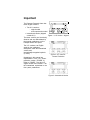
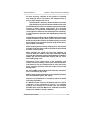
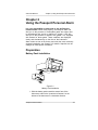
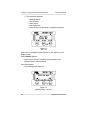
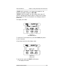
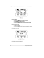
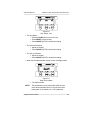
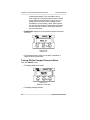
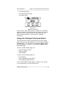
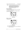
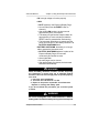
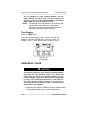
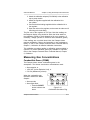
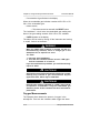
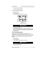
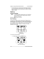
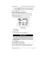
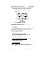
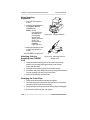
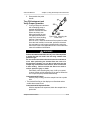
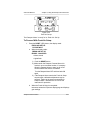
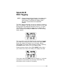
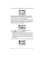
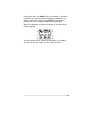
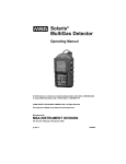
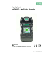
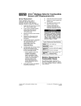
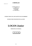
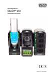
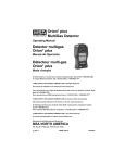
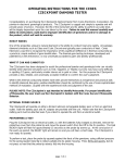
® Passport Personal Alarm Instruction Manual " WARNING THIS MANUAL MUST BE CAREFULLY READ BY ALL INDIVIDUALS WHO HAVE OR WILL HAVE THE RESPONSIBILITY FOR USING OR SERVICING THE PRODUCT. Like any piece of complex equipment, the PASSPORT PERSONAL ALARM will perform as designed only if it is used and serviced in accordance with the manufacturer’s instructions. OTHERWISE IT COULD FAIL TO PERFORM AS DESIGNED AND PERSONS WHO RELY ON THIS PRODUCT FOR THEIR SAFETY COULD SUSTAIN SEVERE PERSONAL INJURY OR DEATH. The warranties made by Mine Safety Appliances Company with respect to the product are voided if the product is not used and serviced in accordance with the instructions in this manual. Please protect yourself and others by following them. We encourage our customers to write or call regarding this equipment prior to use or for any additional information relative to use or repairs. " CAUTION For safety reasons, this equipment must be operated by qualified personnel only. Read and understand the instruction manual completely before operating. In the U.S., to contact your nearest stocking location, dial toll-free 1-800-MSA-2222. To contact MSA International, dial 1-412-967-3000 or 1-800-MSA-7777. This manual pertains to instruments with Serial Number prefix "C". © MINE SAFETY APPLIANCES COMPANY 2005 - All Rights Reserved Manufactured by MSA INSTRUMENT DIVISION P.O. Box 427, Pittsburgh, Pennsylvania 15230 (L) Rev 13 803917 MSA Portable Instrument Warranty 1. Warranty- This product has a warranty on the chassis and electronics. This warranty does not apply to expendable or consumable parts whose normal life expectancy is less than one (1) year such as, but not limited to, batteries, sensors, and pump drive units. Combustible gas sensors, oxygen sensors, carbon monoxide and hydrogen sulfide sensors, battery packs and pumps are limited to one year from date of sale. This warranty does not cover filters, fuses, etc. Certain sensors and other accessories not specifically listed here may have different warranty periods. This warranty is valid only if the product is maintained and used in accordance with Seller’s instructions and/or recommendations. The Seller shall be released from all obligations under this warranty in the event repairs or modifications are made by persons other than its own or authorized service personnel or if the warranty claim results from physical abuse or misuse of the product. No agent, employee or representative of the Seller has any authority to bind the Seller to any affirmation, representation or warranty concerning this product. Seller makes no warranty concerning components or accessories not manufactured by the Seller, but will pass on to the Purchaser all warranties of manufacturers of such components. THIS WARRANTY IS IN LIEU OF ALL OTHER WARRANTIES, EXPRESSED, IMPLIED OR STATUTORY, AND IS STRICTLY LIMITED TO THE TERMS HEREOF. SELLER SPECIFICALLY DISCLAIMS ANY WARRANTY OF MERCHANTABILITY OR OF FITNESS FOR A PARTICULAR PURPOSE. 2. Exclusive Remedy- It is expressly agreed that Purchaser’s sole and exclusive remedy for breach of the above warranty, for any tortious conduct of Seller, or for any other cause of action, shall be the repair and/or replacement at Seller’s option, of any equipment or parts thereof, which after examination by Seller is proven to be defective. Replacement equipment and/or parts will be provided at no cost to Purchaser, F.O.B. Seller’s Plant. Failure of Seller to successfully repair any nonconforming product shall not cause the remedy established hereby to fail of its essential purpose. 3. Exclusion of Consequential Damages- Purchaser specifically understands and agrees that under no circumstances will seller be liable to purchaser for economic, special, incidental or consequential damages or losses of any kind whatsoever, including but not limited to, loss of anticipated profits and any other loss caused by reason of nonoperation of the goods. This exclusion is applicable to claims for breach of warranty, tortious conduct or any other cause of action against seller. Important The Passport Personal Alarm has three keypad versions: • Two U.S. versions - original model - current production model • International version (shipped Figure 1. U.S. Version - Original outside U.S.). The three versions are functionally identical and are differentiated by the keypad pushbuttons on the Passport Alarm front panel. The U.S. versions use English words on the pushbutton descriptions, while the International version uses internationally-recognized symbols (or icons). Illustrations in this manual are representative of the U.S. current production version (FIGURE 2). Refer to FIGURE 1 for the U.S. original version and FIGURE 3 for the International equivalents to the front panel pushbuttons. Figure 2. U.S. Version Current Production Figure 3. International Version Instruction Manual Table of Contents Table of Contents Chapter 1 Safety and General Limitations. . . . . . . . . . . . . . . . . . . . 1-1 Certifications . . . . . . . . . . . . . . . . . . . . . . . . . . . . . . . . . . . . . . 1-1 Electromagnetic Interference . . . . . . . . . . . . . . . . . . . . . 1-1 " !WARNING . . . . . . . . . . . . . . . . . . . . . . . . . . . . . . . . . . . 1-2 "! CAUTIONS. . . . . . . . . . . . . . . . . . . . . . . . . . . . . . . . . . . 1-4 Chapter 2 Using the Passport Personal Alarm. . . . . . . . . . . . . . . . 2-1 Preparation . . . . . . . . . . . . . . . . . . . . . . . . . . . . . . . . . . . . . . . 2-1 Battery Pack Installation . . . . . . . . . . . . . . . . . . . . . . . . . 2-1 Figure 2-1. Battery Pack Installation . . . . . . . . . . . . . 2-1 Figure 2-2. Self Test. . . . . . . . . . . . . . . . . . . . . . . . . . 2-2 Figure 2-3. Operating Beep - No/Yes? . . . . . . . . . . . 2-2 Figure 2-4. Time and Date Set . . . . . . . . . . . . . . . . . 2-3 Figure 2-5. Power OFF . . . . . . . . . . . . . . . . . . . . . . . 2-3 Figure 2-6. Time Set . . . . . . . . . . . . . . . . . . . . . . . . . 2-4 Figure 2-7. Time Set Complete . . . . . . . . . . . . . . . . . 2-4 Figure 2-8. Day, Month, Year . . . . . . . . . . . . . . . . . . 2-5 Figure 2-9. Date Set Complete . . . . . . . . . . . . . . . . . 2-5 Turning ON the Passport Personal Alarm . . . . . . . . . . . 2-6 Figure 2-10. Power OFF . . . . . . . . . . . . . . . . . . . . . . 2-6 Figure 2-11. Measure: Power ON . . . . . . . . . . . . . . . 2-6 Using the Passport Personal Alarm . . . . . . . . . . . . . . . . . . . 2-7 Figure 2-12. Measure: Please wait . . . . . . . . . . . . . . 2-7 Exposure Display . . . . . . . . . . . . . . . . . . . . . . . . . . . . . . . 2-8 Figure 2-13. Exposure Page . . . . . . . . . . . . . . . . . . . 2-8 Figure 2-14. Battery Condition . . . . . . . . . . . . . . . . . . 2-8 "! WARNING . . . . . . . . . . . . . . . . . . . . . . . . . . . . . . . . . . . 2-9 "! WARNING . . . . . . . . . . . . . . . . . . . . . . . . . . . . . . . . . . . 2-9 Time Display. . . . . . . . . . . . . . . . . . . . . . . . . . . . . . . . . . 2-10 Calibration Check . . . . . . . . . . . . . . . . . . . . . . . . . . . . . . . . . 2-10 "! CAUTION . . . . . . . . . . . . . . . . . . . . . . . . . . . . . . . . . . . 2-10 Figure 2-15. Time Display . . . . . . . . . . . . . . . . . . . . 2-10 Measuring Gas Concentrations . . . . . . . . . . . . . . . . . . . . . . 2-11 Combustible Gases (COMB) . . . . . . . . . . . . . . . . . . . . . 2-11 Figure 2-16. Combustible Gas Alarm Flag . . . . . . . 2-11 Passport Personal Alarm TOC-1 Table of Contents Instruction Manual " WARNING . . . . . . . . . . . . . . . . . . . . . . . . . . . . . . . . . 2-12 "! CAUTION #1 . . . . . . . . . . . . . . . . . . . . . . . . . . . . . . . 2-12 "! CAUTION #2 . . . . . . . . . . . . . . . . . . . . . . . . . . . . . . . 2-12 Oxygen Measurements. . . . . . . . . . . . . . . . . . . . . . . . . . 2-12 " WARNING . . . . . . . . . . . . . . . . . . . . . . . . . . . . . . . . . 2-13 Toxic Gas Measurement . . . . . . . . . . . . . . . . . . . . . . . . 2-13 " WARNING . . . . . . . . . . . . . . . . . . . . . . . . . . . . . . . . . 2-13 Figure 2-17. Oxygen Alarm Flag . . . . . . . . . . . . . . . 2-13 Options. . . . . . . . . . . . . . . . . . . . . . . . . . . . . . . . . . . . . . . . . . 2-14 Optional Displays . . . . . . . . . . . . . . . . . . . . . . . . . . . . . . 2-14 Peak Readings . . . . . . . . . . . . . . . . . . . . . . . . . . . . . 2-14 Figure 2-18. Peak Readings. . . . . . . . . . . . . . . . . . . 2-14 Figure 2-19. Reset Peak Readings . . . . . . . . . . . . . 2-14 Short Term Exposure Limit (STEL) . . . . . . . . . . . . . 2-15 "! WARNING . . . . . . . . . . . . . . . . . . . . . . . . . . . . . . . . . 2-15 Time Weighted Average (TWA) . . . . . . . . . . . . . . . . 2-15 Figure 2-20. STEL Alarm Flag . . . . . . . . . . . . . . . . . 2-15 Figure 2-21. Reset TWA Page . . . . . . . . . . . . . . . . . 2-16 " WARNING . . . . . . . . . . . . . . . . . . . . . . . . . . . . . . . . . 2-17 Optional Sampling Equipment . . . . . . . . . . . . . . . . . . . 2-17 Pump Module Option . . . . . . . . . . . . . . . . . . . . . . . . . . . 2-17 " CAUTION . . . . . . . . . . . . . . . . . . . . . . . . . . . . . . . . . . 2-17 Removing the Pump Module . . . . . . . . . . . . . . . . . . 2-17 Using Sampling Equipment: . . . . . . . . . . . . . . . . . . . 2-17 Attaching Probe to Sampling Line (FIGURE 2-24) . 2-18 Changing the Probe Filter. . . . . . . . . . . . . . . . . . . . . 2-18 Figure 2-22. Pump Installation . . . . . . . . . . . . . . . . 2-18 Figure 2-23. Attaching Probe to Sample Line . . . 2-18 Turn ON Instrument and Verify Proper Operation. . 2-19 " WARNING . . . . . . . . . . . . . . . . . . . . . . . . . . . . . . . . . 2-19 Figure 2-24. Changing the Probe Filter . . . . . . . . 2-19 "! CAUTION . . . . . . . . . . . . . . . . . . . . . . . . . . . . . . . . . . 2-20 Removing Sampling Equipment . . . . . . . . . . . . . . . . 2-20 Fresh Air Set Up Option . . . . . . . . . . . . . . . . . . . . . . . . 2-20 "! WARNING . . . . . . . . . . . . . . . . . . . . . . . . . . . . . . . . . 2-20 To Proceed With Fresh Air Setup: . . . . . . . . . . . . . . 2-21 Figure 2-25. Fresh Air Set-up. . . . . . . . . . . . . . . . . 2-201 TOC-2 Passport Personal Alarm Instruction Manual Table of Contents To Bypass The Fresh Air Set Up: . . . . . . . . . . . . . Turning OFF the Passport Alarm . . . . . . . . . . . . . . . . . Figure 2-26. Power Down . . . . . . . . . . . . . . . . . . . . Battery Pack Removal . . . . . . . . . . . . . . . . . . . . . . . . . Recharging Nickel-Cadmium (Ni-Cd) Battery Packs . . Figure 2-27. Ni-Cd Charger (120V version shown) 2-22 2-22 2-22 2-22 2-23 2-23 Chapter 3 General Maintenance . . . . . . . . . . . . . . . . . . . . . . . . . . . . 3-1 " WARNING . . . . . . . . . . . . . . . . . . . . . . . . . . . . . . . . . . Cleaning and Routine Care . . . . . . . . . . . . . . . . . . . . . . . . . . "! CAUTION. . . . . . . . . . . . . . . . . . . . . . . . . . . . . . . . . . . Figure 3-1. Sensor Cover Plate . . . . . . . . . . . . . . . . . Storage . . . . . . . . . . . . . . . . . . . . . . . . . . . . . . . . . . . . . . . . . . Storage for Models with Nitric Oxide (NO) Sensors . . . "! WARNING . . . . . . . . . . . . . . . . . . . . . . . . . . . . . . . . . . Shipment . . . . . . . . . . . . . . . . . . . . . . . . . . . . . . . . . . . . . . . . . 3-1 3-1 3-1 3-1 3-2 3-2 3-2 3-2 Chapter 4 Performance Specifications . . . . . . . . . . . . . . . . . . . . . . . 4-1 Performance Specifications . . . . . . . . . . . . . . . . . . . Relative Responses to Combustible Gases . . . . . . . . . . Interference Gases Cross Sensitivity . . . . . . . . . . . . . . . Carbon Monoxide Sensors . . . . . . . . . . . . . . . . . . . Hydrogen Sulfide Sensors . . . . . . . . . . . . . . . . . . . . Nitric Oxide Sensors . . . . . . . . . . . . . . . . . . . . . . . . Nitric Dioxide Sensors . . . . . . . . . . . . . . . . . . . . . . . Sulfur Dioxide Sensors . . . . . . . . . . . . . . . . . . . . . . 4-1 4-2 4-3 4-3 4-3 4-3 4-3 4-3 Chapter 5 Parts List . . . . . . . . . . . . . . . . . . . . . . . . . . . . . . . . . . . . . . 5-1 Table 5-1. Parts List . . . . . . . . . . . . . . . . . . . . . . . . 5-1 Appendix A Supplemental Instructions for Passport Instruments Supplied with Chlorine (Cl2) Sensors . . . . . . . . . . . . . A-1 "! WARNING . . . . . . . . . . . . . . . . . . . . . . . . . . . . . . . . . . A-2 Interference Gases Cross Sensitivity . . . . . . . . . . . A-2 Appendix B Data Tagging . . . . . . . . . . . . . . . . . . . . . . . . . . . . . . . . . . B-1 Passport Personal Alarm TOC-3 Instruction Manual Chapter 1, Safety and General Limitations Chapter 1 Safety and General Limitations Certifications Tests completed by MSA verify that the Passport Personal Alarm meets applicable industry and government standards (as of date of manufacture), including those for Electromagnetic Interference. Electromagnetic Interference This equipment has been type tested and found to comply with the limits for a Class A digital device, pursuant to Part 15 of the FCC Rules. These limits are designed to provide reasonable protection against harmful interference when the equipment is operated in a commercial environment. This equipment generates, uses, and can radiate radio frequency energy and, if not installed and used in accordance with the instruction manual, may cause harmful interference to radio communications. Operation of this equipment in a residential area is likely to cause harmful interference in which case the user will be required to correct the interference at his own expense. This equipment was tested and found to comply with the limits for a Class B digital device, pursuant to Part 15 of the FCC Rules. These limits are designed to provide reasonable protection against harmful interference in a residential installation. This equipment generates, uses, and can radiate radio frequency energy and, if not installed and used in accordance with the instructions, may cause harmful interference to radio communications. However, there is no guarantee that interference will not occur in a particular installation. If this equipment does cause harmful interference to radio or television reception, which can be determined by turning the equipment OFF and ON, the user is encouraged to try to correct the interference by one or more of the following measures: • Reorient or relocate the receiving antenna. • Increase the separation between the equipment and receiver. • Connect the equipment into an outlet on a circuit different from that to which the receiver is connected. • Consult the dealer or an experienced radio TV technician for help. Passport Personal Alarm 1-1 Chapter 1, Safety and General Limitations Instruction Manual This digital apparatus does not exceed the Class A limits for radio noise emissions from digital apparatus set out in the Radio Interference Regulations of the CRTC. " WARNING Changes or modifications to this unit not expressly approved by the party responsible for compliance could void the user’s authority to operate the equipment. GENERAL LIMITATIONS and " WARNINGS The Passport Alarm detects gases and vapors in air only. It cannot measure combustible or toxic gases in: - reducing atmospheres - furnace stacks - environments with inert gas backgrounds Do not use the Passport Alarm to measure combustible or toxic gases when the amount of oxygen is: - deficient - enriched The Passport Alarm measures combustible gases and vapors. It cannot measure the presence of combustible: - airborne mists such as lubricating oils - airborne dusts such as grain or coal dust The Passport Alarm contains sensors which detect specific toxic gases. The instrument must be used to detect only those specific gases. Other toxic hazards may be present; the Passport Alarm is not intended to detect these other hazards. Certain materials such as: - silicone - silicates - lead-containing compounds such as leaded gasoline tend to desensitize the combustible gas sensor, thereby giving erroneously low readings. Calibration checks must be made frequently if such materials are suspected to be present in the tested atmosphere. If you do not recalibrate, the instrument may give false readings and endanger life and health. 1-2 Passport Personal Alarm Instruction Manual Chapter 1, Safety and General Limitations For best accuracy, calibrate at the pressure of intended use. Readings will be inaccurate if the Passport Alarm is used to take samples that are at: -low atmospheric pressure (below calibration pressure) -high atmospheric pressure (above calibration pressure) Combustible gases will burn or explode only when the fuel/air mixture is within certain proportions. The minimum concentration of a particular combustible gas in air which can be ignited is defined as the Lower Explosive Limit (LEL). In some references, the term Lower Flammability Limit (LFL) is used. Combustible gas readings with an OVER alarm in the display indicate an amount of gas which may be above the Lower Explosive Limit (LEL) or above 5% methane (CH4) by volume. Such readings are beyond the accurate range of the sensor. (See Chapter 4 for limits.) When sampling with accessory sampling lines, the shortest possible length should be used to minimize the time needed to obtain a valid reading. When sampling over liquids, the end of the sampling line must not touch the surface of the liquid. Otherwise, liquids may enter the instrument, causing internal damage. In addition, sample gas may be blocked from entering the line, and a false reading may occur. Obstruction of the sensor holes in the instrument case causes erroneous readings. These holes must be kept open at all times. Do not use compressed air to clean the sensor holes; excessive pressure at the face of the sensors could damage them. Do not use MSA Lead Inhibitor Filters with this instrument. Loss of sensitivity may result. Battery packs must be recharged in a non-hazardous location free of combustible gases and vapors. Dispose of used batteries in accordance with local health and safety regulations. A calibration check should be included as part of a routine inspection of this instrument to ensure it is operating properly and readings are accurate. See the Passport Portable Alarm Technical Manual for calibration procedure details and calibration kit part numbers. Passport Personal Alarm 1-3 Chapter 1, Safety and General Limitations Instruction Manual Use only genuine MSA replacement parts when performing any maintenance procedures described in this manual. Substitution of components may seriously impair instrument performance, alter intrinsic safety characteristics, or void agency approvals. Repair or alteration of the Passport Alarm beyond the procedures described in this manual could cause the instrument to fail to perform properly. " CAUTIONS Acid gases, such as carbon dioxide, will shorten the service life of the oxygen sensor. Do not push on the center of the oxygen or the toxic gas sensor. Be especially careful when installing or replacing a sensor. Damage to the sensor may result. This instrument is designed for use only with the battery chargers listed in this manual. Use of other battery chargers may result in damage to the battery pack and instrument. Before each day’s use, perform a calibration check (see Chapter 2, "Calibration Check") and check the pump (if used) for proper operation. (See Chapter 2, "Pump Operation.") 1-4 Passport Personal Alarm Instruction Manual Chapter 2, Using the Passport Personal Alarm Chapter 2 Using the Passport Personal Alarm It is your responsibility to know how to use the Passport Personal Alarm. When used properly, the Passport Alarm will alert you to the presence of combustible gases and vapors and to atmospheres that are rich or deficient in oxygen. It will also alert you to the presence of specific toxic gases if it is equipped with sensors for those gases. These conditions are displayed clearly and simultaneously on the face of the instrument. Alarm levels are set at the factory and meet the most commonly accepted standards; see Chapter 4 for details. Setpoints can be changed to meet specific conditions. Preparation Battery Pack Installation Figure 2-1. Battery Pack Installation 1. Slide the battery pack toward the sensor face of the instrument, and turn the "quarter-turn fastener" on the bottom of the instrument in a clockwise direction. Passport Personal Alarm 2-1 Chapter 2, Using the Passport Personal Alarm Instruction Manual 2. The instrument responds: • backlight flashes • screen flashes • alarm sounds • alarm lights flash • major electronic components are tested automatically Figure 2-2. Self Test After tests are completed, either ERROR or OK appears on the display screen. When ERROR appears: • Alarm sounds; see the Troubleshooting Guidelines in the Passport Alarm Technical Manual. When OK appears: • The following display appears: Figure 2-3. Operating Beep - No/Yes? 2-2 Passport Personal Alarm Instruction Manual Chapter 2, Using the Passport Personal Alarm If PAGE (NO) is pressed, or no buttons are pressed for five seconds, the display changes to SET TIME. If RESET (YES) is pressed, the alarm beeps about every 30 seconds, indicating the Passport Alarm is turned ON. The beep does not occur if YES is not selected or the Passport Alarm is turned OFF. The display now reads: Figure 2-4. Time and Date Set To cancel the Time and date set, press the PAGE (NO) button or wait 5 seconds. A long beep sounds and the display reads: Figure 2-5. Power OFF To set the time, press the RESET (YES) button. • The display now reads: Passport Personal Alarm 2-3 Chapter 2, Using the Passport Personal Alarm Instruction Manual Figure 2-6. Time Set • The hour flashes • Press the PAGE button to lower the hours. • Press RESET to raise the hours • Press the ON/OFF button to accept the new number. • The minutes now flash. • Adjust as needed. • Press the ON/OFF (NEXT) button to accept the reading. • The display now reads: Figure 2-7. Time Set Complete • The display automatically displays: 2-4 Passport Personal Alarm Instruction Manual Chapter 2, Using the Passport Personal Alarm Figure 2-8. Day, Month, Year • The day flashes. • Press the PAGE button to lower the day. • Press RESET to raise the day. • Press ON/OFF (NEXT) to accept the reading. • The month now flashes. • Adjust as needed. • Press ON/OFF (NEXT) to accept the reading. • The year now flashes. • Adjust as needed. • Press ON/OFF (NEXT) to accept the reading. • When the selected time/date values are set, the display reads: Figure 2-9. Date Set Complete • The Alarm sounds. NOTE: The small battery on the main board which runs the clock has an estimated life of 5-10 years if the main battery pack is not installed, or if it is installed but Passport Personal Alarm 2-5 Chapter 2, Using the Passport Personal Alarm Instruction Manual completely discharged. This clock battery has a much longer life if a charged battery pack is installed on the Passport Personal Alarm. If the clock is not holding the correct time when the battery pack is reinstalled, the clock battery is dead. Either replace the main board or send the Passport Personal Alarm to a service center to have a new battery soldered onto the main board. • POWER OFF displays for a few seconds, and the instrument turns OFF. Figure 2-10. Power OFF • The Passport Alarm is ready for use after a calibration or response check is performed. Turning ON the Passport Personal Alarm Push the ON/OFF button. • The display flashes and reads: Figure 2-11. Measure: Power ON • The display backlight flashes 2-6 Passport Personal Alarm Instruction Manual Chapter 2, Using the Passport Personal Alarm • The alarm lights flash • The alarm sounds and stops • The display reads: Figure 2-12. Measure: Please wait If the Fresh Air Setup (FAS) feature is enabled, the combustible and toxic sensors can be zeroed, and the oxygen sensor can be spanned to 20.8%. FAS must only be used in fresh air. (See Fresh Air Setup Option later in this Chapter for additional information.) Using the Passport Personal Alarm The Passport Alarm has three standard and three optional display pages. You can move sequentially from one to the next by pressing the PAGE button. You can return to the standard Exposure display page by waiting for 15 seconds or by pressing the ON/OFF button from another page. The three standard display pages are: • Exposure display (normal) • Battery condition • Time and date The three optional display pages are: • Peak readings • Short Term Exposure Limit (STEL) • Time Weighted Average (TWA) If any of these optional display pages is enabled, it will appear on your instrument in the order shown above. Passport Personal Alarm 2-7 Chapter 2, Using the Passport Personal Alarm NOTE: Instruction Manual The Passport Personal Alarm measures concentrations of gases no matter what display page is shown. When an alarm condition is reached, the alarm sounds automatically. The measurements made by the Passport Alarm are NOT dependent upon a specific display page being shown. Exposure Display In this normal display page, numbers appear near the gas labels on the instrument’s display panel: To change from the Exposure display to the Battery Condition page, press the PAGE button. Figure 2-13. Exposure Page Battery Condition The display reads: Figure 2-14. Battery Condition • v.v is the voltage from the battery • cccc is one of three battery conditions that can be displayed on the Battery display page: 2-8 Passport Personal Alarm Instruction Manual Chapter 2, Using the Passport Personal Alarm • OK: enough voltage to function properly • LOW: • BATT appears in the Exposure Display Page • Horn sounds (Press the RESET button to silence it.) • After initial LOW warning, the horn sounds approximately every five minutes • The battery will operate the Passport Alarm for approximately 10 more minutes provided the RESET button is pressed after each warning. • The instrument will continue to operate until the power is turned OFF or the battery condition is at BATTERY SHUTDOWN level. • BATTERY SHUTDOWN: the battery is no longer able to operate the instrument, and: • BATTERY SHUTDOWN appears in place of the Exposure Display Page. Horn sounds continuously and cannot be reset. • Alarm lights flash. • No other pages can be viewed. • After approximately five minutes, the instrument shuts down automatically. " WARNING When the Battery Shutdown condition sounds, stop using the instrument. It cannot alert you of potential hazards because it does not have enough power to operate properly. You must: 1. Leave the area immediately. 2. Turn OFF the instrument if it is ON. 3. Report to the person responsible for maintenance. Replace or recharge the battery pack. If you do not follow this procedure, you could be injured or killed. "!WARNING Do not use rechargeable nickel cadmium batteries in Alkaline battery packs. The Alkaline battery warning and alarm setpoints Passport Personal Alarm 2-9 Chapter 2, Using the Passport Personal Alarm Instruction Manual are not optimized for nickel cadmium batteries. The low battery warning and alarm could occur too quickly to be noticed. If you do use nickel cadmium batteries in the alkaline battery pack you could be injured or killed. NOTE: The Passport unit recognizes the type of battery pack (rechargeable nickel cadmium or replaceable alkaline) is attached and automatically adjusts the low battery warning and alarm setpoints. Time Display Press the PAGE button In the third standard display page, the time and date are displayed. The time is displayed in a 24-hour format. For example, "Sept. 1 1992" would read as follows at 3 p.m.: Figure 2-15. Time Display Calibration Check " CAUTION The following calibration check should be performed before each day’s use. This calibration check is very simple and should only take one to five minutes, depending on the number and type of gases your Passport Alarm is equipped to sense. Turn the Passport Alarm ON in clean fresh air, and verify that the readings indicate no gas present. If necessary, perform the procedure given in Fresh Air Setup Option later in this Chapter. 1. Attach the pump module or calibration cap to the Passport Alarm, orienting the inlet fitting to point toward the battery pack. 2-10 Passport Personal Alarm Instruction Manual Chapter 2, Using the Passport Personal Alarm 2. Attach the calibration adapter (P/N 636246) to the calibration cap or pump module. 3. Attach the regulator supplied with the calibration kit to the cylinder. 4. Connect the black tubing supplied with the calibration kit to the regulator. 5. Open the valve on the regulator, and connect the other end of the tubing to the inlet fitting. The flow rate of the regulator is 0.25 lpm. Note the readings on the Passport display; they should be within the limits stated on the calibration cylinder or limits determined by your company. (If necessary, change cylinders to introduce other calibration gases.) If the readings are not within these limits, the Passport Alarm requires recalibration. Return the instrument to your maintenance facility, or refer to the Passport Personal Alarm Technical Manual, Chapter 2, Calibration for detailed calibration instructions. This calibration procedure applies to calibration gases available in cylinders. For those calibration gases only available in ampoules, refer to the Passport Personal Alarm Technical Manual, Chapter 2, Calibration. Measuring Gas Concentrations Combustible Gases (COMB) The Passport Alarm detects combustible gases in the atmosphere. The Alarms sound when concentrations reach: • Alarm setpoint, or • 100% LEL (Lower Explosive Limit), or • 5% CH4 (Methane by volume) When the combustible gas indication reaches the Alarm Setpoint: • Alarm sounds • Alarm lights flash; • Press the RESET button to silence the alarm. Passport Personal Alarm Figure 2-16. Combustible Gas Alarm Flag 2-11 Chapter 2, Using the Passport Personal Alarm Instruction Manual • Concentration of gas flashes in the display. When the combustible gas indication reaches 100% LEL or 5% CH4 of the combustible gas: • Alarm sounds; • This alarm cannot be reset with the RESET button. The LockAlarm circuit locks the combustible gas reading and alarm if the gas reading exceeds 100% LEL or 5% methane. • OVER appears on the display. The alarm can be reset by turning off the instrument and moving to a safe, fresh-air environment. " WARNING When the OVER alarm condition is reached, you are in a life-threatening situation; there is enough gas in the atmosphere for an explosion to occur. You must: 1. Leave the area immediately. 2. Turn OFF the instrument and do not turn it ON again until the instrument is in fresh air. If you do not follow this procedure, you could be seriously injured or killed. " CAUTION #1 Any Rapid up-scale reading followed by a declining or erratic reading may indicate a gas concentration beyond upper-scale limit, which may be hazardous. " CAUTION #2 High off-scale readings (indicated by "OVER") may indicate an explosive concentration. Only the combustible gas detection portion of this instrument has been assessed for performance. Oxygen Measurements The Passport Alarm detects the amount of oxygen in the atmosphere. There are two conditions which trigger the alarm: 2-12 Passport Personal Alarm Instruction Manual Chapter 2, Using the Passport Personal Alarm • Too little oxygen (deficient) • Too much oxygen (enriched) At the Alarm Setpoint for either: • Alarm sounds • Alarm light flashes • Concentration of gas flashes in the display Figure 2-17. Oxygen Alarm Flag " WARNING When the OXYGEN alarm sounds, you may be in a life-threatening situation. You must follow your company’s work and safety procedures. If you do not follow those procedures you could be seriously injured or killed. Toxic Gas Measurement The Passport Alarm detects certain toxic gases in the atmosphere. Your instrument may have one, two, or three toxic sensors. Each of these sensors has a setpoint which causes an alarm if the gas level goes above that setpoint. When this happens: • Alarm sounds • Alarm lights flash • Concentration of gas flashes in the display " WARNING When the TOXIC GAS alarm sounds, you may be in a life-threatening situation. Passport Personal Alarm 2-13 Chapter 2, Using the Passport Personal Alarm Instruction Manual You must follow your company’s work and safety procedures. If you do not follow those procedures you could be seriously injured or killed. Options Optional Displays NOTE: The following display pages appear only if enabled by internal switches; see the Passport Alarm Technical Manual for instructions. Press the PAGE button to move to: Peak Readings This shows the highest levels of gas that the Passport Alarm recorded since it was turned ON or since the peak readings were reset. Passport Personal Alarm units with serial number prefix C-4 and higher have an added feature in the Peak page. Both the high and low oxygen readings are displayed. All other functions are the same. Figure 2-18. Peak Readings To reset the Peak Readings: 1. In Peak display, press the RESET button. Figure 2-19. Reset Peak Readings 2-14 Passport Personal Alarm Instruction Manual Chapter 2, Using the Passport Personal Alarm 2. Press the RESET (YES) button to reset peak readings or press the PAGE (NO) button or wait 15 seconds to cancel. Press the PAGE button to move to: Short Term Exposure Limit (STEL) This shows the average exposure over a 15 minute period. When the amount of gas detected by the Passport Alarm is greater than the STEL limit: • On the Exposure display page, the screen displays: Figure 2-20. STEL Alarm Flag • Alarm sounds • Alarm lights flash To reset the alarm: • In the STEL display, press the RESET button. " WARNING When the STEL alarm sounds you may be exposed to a concentration of gas that is dangerous to your life and health. You must follow your company’s work and safety procedures. If you do not follow those procedures you could be seriously injured or killed. Press the PAGE button to move to: Time Weighted Average (TWA) TWA is the average exposure since the TWA reading was reset. The TWA reading may be reset using the following procedure: Passport Personal Alarm 2-15 Chapter 2, Using the Passport Personal Alarm Instruction Manual • Turn the Passport Alarm OFF for eight or more hours or • Press the PAGE button until the TWA screen appears • Press the RESET button; the message appears on the display. Figure 2-21. Reset TWA Page • Press the RESET (YES) button. When the amount of gas detected by the Passport Alarm is greater than the eight-hour TWA limit: • Alarm sounds • Alarm lights flash • On the Exposure display page, the screen displays the TWA alarm flag. The TWA alarm is calculated over an eight-hour exposure. Calculation examples are as follows: • 1-hour exposure of 50 PPM: ((1 hour x 50 PPM) + (7 hours x 0 PPM)) = 6.25 PPM 8 hours • 4-hour exposure of 50 PPM 4-hour exposure of 100 PPM: ((4 hours x 50 PPM) + (4 hours x 100 PPM)) = 75 PPM 8 hours • 12-hour exposure of 100 PPM: (12 hours x 100 PPM) = 150 PPM 8 hours NOTE: 2-16 The accumulated reading is always divided by eight hours. Passport Personal Alarm Instruction Manual Chapter 2, Using the Passport Personal Alarm To reset the alarm: • In the TWA display, press the RESET button. " WARNING When the TWA alarm sounds you may be exposed to a concentration of gas that is dangerous to your life and health. You must follow your company’s work and safety procedures. If you do not follow those procedures you could be seriously injured or killed. You may press PAGE button to move to the Exposure display. Optional Sampling Equipment Sampling lines and related equipment permit samples of gas to be taken from remote or inaccessible locations. Sampling lines are 5 to 50 feet long and are made of a synthetic material specifically compounded to resist absorption of combustible and toxic vapors. Gases are drawn through the lines to the Passport Alarm by a pump. Using the shortest possible line reduces the time the pump must run before valid samples and readings can be obtained. Pump Module Option When ordered, the pump module is packed separately and may be installed before using the Passport Alarm: 1. Position the pump module as shown, the inlet must point toward the battery. 2. Hand-tighten the screws until snug. " CAUTION Do not overtighten the screws. Removing the Pump Module 1. Loosen screws. 2. Remove pump module. Passport Personal Alarm 2-17 Chapter 2, Using the Passport Personal Alarm Instruction Manual Using Sampling Equipment: 1. Turn OFF the Passport Alarm. 2. Install the Pump Module if it is not already attached (FIGURE 2-22). NOTE: Do not over-tighten the thumb screws on the pump module in an effort to eliminate a leak. The thumb screws should be finger-tight only. Figure 2-22. Pump Installation 3. Attach the Sampling Hose to the Pump Module as shown. See FIGURES 2-23 and 2-24. Attaching Probe to Sampling Line (FIGURE 2-24) Figure 2-23. Attaching Probe to Sample Line 1. Grasp the probe handle by the top two sections [the large section (cap) with the MSA logo and the center section (base) with the label]. 2, Unscrew lower section (guard) from the label section. 3. Feed male end of the sample line through the guard and screw into the exposed connector ring on the probe. 4. Screw the guard back onto the base. Changing the Probe Filter 1. Grasp the probe handle by the base and guard. 2. Push the cap section toward the other two and turn clockwise (the spring will push the sections apart). 3. Grasp and spin the wand clockwise while pulling to disengage. 4. Remove the water trap filter and replace. 2-18 Passport Personal Alarm Instruction Manual Chapter 2, Using the Passport Personal Alarm 5. Re-assemble the probe handle. Turn ON Instrument and Verify Proper Operation 1. If using a Passport instrument with a sampling pump or aspirator bulb assembly, perform a blocked flow test before each day’s use. When performing the test, the appropriate indication Figure 2-24. Changing the must occur when blocking Probe Filter the flow. If the indication does not occur, check the instrument flow system for leaks. Once the leak condition is corrected, perform the blocked flow test again to verify proper operation before using the instrument. Refer to the applicable section in this instruction manual for additional information. " WARNING Perform a blocked flow test before each day’s use. Failure to perform a blocked flow test can result in the user being unaware of the presence of gas. Do not use the instrument unless the blocked flow indications occur when performing the blocked flow test. Lack of a blocked flow indication is a sign that a leak exists and the sample may not be drawn to the sensors, which could cause a false reading. Failure to follow the above can result in serious personal injury or death. Periodically, while checking the pump, it will try to restart. It cannot restart until the sampling line is opened. When the line is open the pump restarts automatically. Instruments with Pumps: With the pump running, block the sample line inlet or probe inlet. • The blocked flow flag on the display must illuminate and an audible alarm must sound. Instruments with Aspirator Bulbs: With the aspirator bulb squeezed, block the sample inlet or probe inlet. Passport Personal Alarm 2-19 Chapter 2, Using the Passport Personal Alarm Instruction Manual • The bulb must not inflate. • Please note that some instruments with electronic flow indicators can have optional aspirator bulb accessories. • The electronic flow indicators are not intended to activate when the aspirator is attached. If there are questions regarding this information, please contact MSA Customer Service at: 1800-MSA-2222. 2. Press the RESET button to reset the alarm. " CAUTION Never let the end of the sampling line touch or go under any liquid surface. If liquid is sucked into the instrument, readings will be inaccurate and the instrument could be damaged. We recommend the use of an MSA Sample Probe (part no. 497600, 800332, 800333, or equivalent) containing a special membrane filter, permeable to gas but impermeable to water, to prevent such an occurrence. Removing Sampling Equipment 1. Turn OFF the Passport Alarm. 2. Unscrew the connector ring on the sampling line, and remove the sampling line. Fresh Air Set Up Option (for automatic zero adjustment of the Passport Alarm sensors) NOTE: The Fresh Air setup has limits. If a dangerous level of gas is present, the Passport Alarm ignores the FAS command and goes into alarm. " WARNING Do not activate the fresh air setup unless you are certain you are in fresh, uncontaminated air; otherwise, inaccurate readings may occur. These inaccurate readings may falsely indicate that a hazardous atmosphere is safe, and injury or death could occur. If you have any doubts as to the quality of the surrounding air, do not use the fresh air setup feature. When the display reads: 2-20 Passport Personal Alarm Instruction Manual Chapter 2, Using the Passport Personal Alarm Figure 2-25. Fresh Air Set-up The Passport Alarm is ready for its Fresh Air Set Up. To Proceed With Fresh Air Setup: 1. Press the RESET (YES) button; the display reads: FRESH AIR SET UP PLEASE WAIT a. When the display reads: FRESH AIR SET UP ERROR - CANCELED • Alarm sounds • Lights flash 1) Push the RESET button. 2) Make certain the Passport Personal Alarm is in fresh air; move to another location, if necessary. Allow the Passport Alarm to warm up for a few minutes toallow the sensors to stabilize. Turn the Passport Alarm OFF and then back ON again. 3) If the Passport Alarm cancels the Fresh air Setup request again, calibration adjustments may be required. Report to the person responsible for Passport Alarm maintenance. Do not use the instrument for protection. b. When the Fresh Air Setup is completed: Instrument enters the Exposure display page and displays gas readings. Passport Personal Alarm 2-21 Chapter 2, Using the Passport Personal Alarm Instruction Manual • Instrument is ready for use. To Bypass The Fresh Air Set Up: Press the PAGE (NO) button, or wait five seconds. • Display enters Exposure page. • Display begins to show gas readings. • The instrument is ready for use. If the sensors drift off of zero a few minutes after being turned ON, allow the Passport Alarm to warm up for 15 minutes, then try the Fresh Air Setup again. Turning OFF the Passport Alarm Push the ON/OFF button, and hold it for five seconds. A countdown appears: Battery Pack Removal Figure 2-26. Power Down 1. Turn the power OFF by pressing and holding the ON/OFF button for five seconds. • POWER OFF appears on the display. 2. Turn the "quarter-turn fastener" on the back of the instrument in a counterclockwise direction. 3. Slide the battery pack away from the sensor face. 2-22 Passport Personal Alarm Instruction Manual Chapter 2, Using the Passport Personal Alarm Recharging Nickel-Cadmium (Ni-Cd) Battery Packs The Passport Ni-Cd rechargeable battery packs are charged using the Omega battery charging system only. Look for the Omega symbol Ω on the battery pack and charger to make sure they are compatible. Use of any other charger may damage or improperly charge the batteries. The battery pack will be fully recharged after 16 hours. The Passport unit should be turned off or the battery pack should be removed from the Passport unit during charging. Be certain that the charger is properly connected by checking to see that the charger’s LED is lit. No matter how long the Passport unit was run (one hour or a full shift), the battery pack can be left on charge indefinitely without causing damage - providing that the battery pack was recharged at room temperature. The Omega charger will recharge, but not over-charge, the battery pack. The battery pack may be charged when it is connected to the Passport Alarm or when it is removed. If the battery pack is connected to the Passport Alarm: 1. Turn OFF the instrument. 2. Insert the charger plug into the jack on the battery pack. Figure 2-27. Ni-Cd Charger (120V version shown) Passport Personal Alarm 2-23 Chapter 2, Using the Passport Personal Alarm Instruction Manual 3. Plug the charger into a matching receptacle. The red light on the charger lights if the charger is properly connected. PASSPORT OPERATING TIME (without derating/ at 20oC) BATTERY TYPE WITHOUT PUMP WITH PUMP A. NiCd Standard 10-12 hours 8-10 hours B. NiCd Heavy Duty 20-22 hours 16-18 hours 18-20 hours 16 hours C. "C" Alkaline 2-24 Passport Personal Alarm Instruction Manual Chapter 3, General Maintenance Chapter 3 General Maintenance As with all electronic equipment, the Passport Alarm will operate only if it is cared for and maintained properly. " WARNING Repair or alteration of the Passport Alarm beyond the scope of these instructions by anyone other than a person authorized by MSA may void all warranties and approvals. Such repairs may also endanger persons who rely on this equipment for their safety or health. When needed, use only genuine MSA replacement parts. Cleaning and Routine Care The Passport Alarm case should be cleaned periodically with a soft cloth dampened with water. If any sensor holes on the front of the instrument are blocked with dirt, they must be cleaned: 1. Remove the sensor cover plate. 2. Clean the holes in the plate with a paper clip, wire, or similar device. The holes may also be cleaned with oil-free compressed air. Figure 3-1. Sensor Cover Plate " CAUTION Do not attempt to clean the sensor cover plate while it is in place; otherwise, the sensors may be damaged. The tops of sensors are very fragile. Do not touch or apply pressure to the tops of any sensors. If a sensor is damaged it may cause the instrument to give false readings. Passport Personal Alarm 3-1 Chapter 3, General Maintenance Instruction Manual The sensor cover plate contains holes for five sensors. In instruments with less than five sensors, some of these holes are permanently blocked with special sealing membranes. Do not puncture these membranes, or erroneous gas readings may result. Storage Store your Passport Alarm in a safe, dry place when it is not in use. Be sure that the storage area temperature is between 23 and 104 degrees Fahrenheit (-5 and 40 degrees Celsius). • When the Passport Alarm is stored for more than one month, rechargeable battery packs should be periodically charged to prevent battery damage. Storage for Models with Nitric Oxide (NO) Sensors These models draw a small amount of power at all times (even when turned OFF) in order to maintain a voltage on toxic gas sensors and keep them ready for immediate use. • When the Passport Alarm is stored for less than 20 days, recharge the rechargeable battery pack or replace alkaline batteries before storing. • To store these models for more than 20 days, attach the unit to a battery charger and charge with the proper MSA charger or periodically replace alkaline batteries with fresh cells. " WARNING After storage, always recheck the calibration of the instrument before use. During storage, sensors may drift or become inoperative and may not provide warnings of danger to the health and lives of users. Shipment 1. Remove the battery pack before shipment. When the Passport Alarm is returned for repairs, disconnect the normally used battery pack from the unit, and include it in the container. 3-2 Passport Personal Alarm Instruction Manual Chapter 3, General Maintenance 2. Pack the Passport Alarm in its original shipping container with suitable padding. If the original container is unavailable, ask your MSA representative for a replacement. An equivalent container may be substituted if necessary. In either case, seal the instrument in a plastic bag to protect it from moisture. Protect the Passport Alarm from the rigors of handling with sufficient padding. Damage due to improper packaging or damage in shipment is not covered by the instrument’s warranty. Passport Personal Alarm 3-3 Instruction Manual Performance Specifications Chapter 4 Chapter 4, Performance Specifications Performance Specifications Range Resolution COMBUSTIBLE GAS Reproducibility Response Time OXYGEN Range Resolution Reproducibility Response Time CARBON MONOXIDE (APPROPRIATE MODELS ONLY) Range Resolution Reproducibility Response Time HYDROGEN SULFIDE (APPROPRIATE MODELS ONLY) Range Resolution Reproducibility Response Time NITROGEN DIOXIDE (APPROPRIATE MODELS ONLY) Range Resolution Reproducibility Response Time NITRIC OXIDE (APPROPRIATE MODELS ONLY) Range Resolution Reproducibility Response Time SULFUR DIOXIDE (APPROPRIATE MODELS ONLY) TEMPERATURE RANGE Range Resolution Reproducibility Response Time Normal Extended Passport Personal Alarm 0 to 100% LEL or 0 to 5% CH4 1% LEL or 0.1% CH4 3% LEL to 50% LEL reading 5% LEL to full scale or 0.2% CH4 to 2.5% Methane 0.3% CH4 to full scale 90% of final reading in 30 seconds (normal temperature range) 0 to 25% O2 0.1% O2 0.3% O2, for 2 to 25% O2 30 seconds (normal temperature range) 90% of final reading 3 minutes (extended temperature range) 1000 ppm CO 1 ppm CO +2 ppm CO or 10% of reading, whichever is greater 90% of final reading in 40 seconds (normal temperature range) 50 ppm H2S 1 ppm H2S +2 ppm H2S or 10% of reading, whichever is greater 90% of final reading in 65 seconds (normal temperature range) 20 ppm NO2 1 ppm NO2 +2 ppm NO2 or 10% of reading, whichever is greater 90% of final reading in 50 seconds (normal temperature range) 100 ppm NO 1 ppm NO +2 ppm NO or 10% of reading, whichever is greater 90% of final reading in 120 seconds (normal temperature range) 20 ppm SO2 1 ppm SO2 +2 ppm SO2 or 10% of reading, whichever is greater 90% of final reading in 65 seconds (normal temp. range) 0 to 40o C -10 to 40o C 4-1 Chapter 4, Performance Specifications, Instruction Manual Relative Responses to Combustible Gases The following relative responses to selected combustible gases are typical of an instrument calibrated using Pentane. COMBUSTIBLE GAS Acetone Acetylene Acrylonitrile1 Benzene Butane 1,3 Butadiene n-Butanol Carbon Disulfide1 Cyclohexane 2,2 Dimethylbutane 2,3 Dimethylpentane Ethane Ethyl Acetate Ethyl Alcohol Ethylene Formaldehyde2 Gasoline (unleaded) Heptane Hydrogen n-Hexane Isobutane Isobutyl Acetate Isopropyl Alcohol Methane Methanol Methyl Isobutyl ketone Methylcyclohexane 4-2 MULTIPLY %LEL READING BY 1.1 0.7 0.8 1.1 1.0 0.9 1.8 2.2 1.1 1.2 1.2 0.7 1.2 0.8 0.7 0.5 1.3 1.1 0.6 1.3 0.9 1.5 1.1 0.5 0.6 1.1 1.1 COMBUSTIBLE GAS MULTIPLY %LEL READING BY Methyl Ethyl Ketone 1.1 Methyl Tertiary Butyl Ether 1.0 Mineral Spirits 1.1 iso-Octane 1.1 n-Pentane 1.0 Propane 0.8 Propylene 0.8 2 Styrene 1.9 Tetrahydrofuran 0.9 Toluene 1.1 Vinyl Acetate 0.9 VM&P Naptha 1.6 0-Xylene 1.2 Response Notes: 1. The compounds may reduce the sensitivity of the combustible gas sensor by poisoning or inhibiting the catalytic action. 2. These compounds may reduce the sensitivity of the combustible gas sensor by polymerizing on the catalytic surface. 3. For an instrument calibrated on Pentane, multiply the displayed %LEL value by the conversion factor above to get the true %LEL. 4. These conversion factors should be used only if the combustible gas is known. 5. These conversion factors are typical for a Passport Portable Alarm. Individual units may vary by + 25% from these values. Passport Personal Alarm Instruction Manual Performance Specifications Chapter 4 Interference Gases Cross Sensitivity SAMPLE PASSPORT RESPONSE Carbon Monoxide Sensors 1000 ppm Toluene/Air 1 0.58% Benzene/Air 1 1.6% Acetone/Air 2 100 ppm Isobutylene/Air 1 0.8% Hydrogen/Air 1000 0.75% Pentane/Air 1 3.9% CO2/N2 1 7.5 ppm Chlorine/Air 0 50 ppm HCl/Air 0 10 ppm HCN/Air 0 50 ppm NO/Air 12 5 ppm NO2/air 0 10 ppm SO2/Air -2 These responses are typical over the entire -10oC to 40oC temperature range. Hydrogen Sulfide Sensors 1000 ppm Toluene/Air 0.58% Benzene/Air 1.6% Acetone/Air 100 ppm Isobutylene/Air 0.8% Hydrogen/Air 0.75% Pentane/Air 3.9% CO2/N2 1.49% Ethanol/Air 7.5 ppm Chlorine/Air 50 ppm HCl/Air 10 ppm HCN/Air 50 ppm NO/Air 5 ppm NO2/Air 10 ppm SO2/Air These responses are typical over the -10oC to 40oC temperature range. Passport Personal Alarm 0 0 0 0 -4 0 0 2 0 0 0 -1 0 1 SAMPLE PASSPORT RESPONSE Nitric Oxide Sensors 10 ppm Hydrogen Sulfide 60 ppm Carbon Monoxide 10 ppm Chlorine 10 ppm Hydrogen Cyanide 10 ppm Nitrogen Dioxide 10 ppm Sulfur Dioxide These responses are typical over the -10oC to 40oC temperature range. 2 0 0 0 0 0 entire Nitric Dioxide Sensors 10 ppm Hydrogen Sulfide -12 100 ppm Carbon Monoxide 0 5 ppm Chlorine 4 50 ppm Hydrogen Chloride -1 10 ppm Hydrogen Cyanide -2 10 ppm Sulfur Dioxide 0 These responses are typical over the entire o o -10 C to 40 C temperature range. Sulfur Dioxide Sensors 10 ppm Hydrogen Sulfide 23 100 ppm Carbon Monoxide 0 5 ppm Chlorine 0 10 ppm Hydrogen Cyanide 2 50 ppm Nitrogen Dioxide -7 These responses are typical over the entire -10oC to 40oC temperature range. NOTES: These conversion factors are typical for a Passport Personal Alarm. Individual units may vary by +25% from these values. entire 4-3 Instruction Manual Chapter 5, Parts List Chapter 5 Parts List Table 5-1. Parts List PART PART NO. Pump Module 497430 Calibration Cap 497367 Battery Pack, Standard Ni-Cd Rechargeable - MET Approval Only 10047801 Probe - 1 ft. 800332 Probe - 3 ft. 800333 Sampling Line - 5 ft. 497332 Sampling Line - 10 ft. 497333 Sampling Line - 15 ft. 497334 Sampling Line - 25 ft. 497335 Replacement Filter, Probe 801582 Charger, Omega 120 VAC 494716 Charger, Omega 220 VAC 495965 Charger, Omega 110/220 VAC, Five Unit 801759 Charger, Omega 12 volt 800525 Calibration Kit Model RP with 0.25 lpm Regulator 477149 Calibration Gas - LEL pentane simulant / 15% O2 478192 Calibration Gas - LEL pentane simulant / 15% O2; 60 ppm CO 478191 Calibration Gas - 10 ppm H2S 467898 Calibration Gas - LEL pentane simulant / 15% O2; 300 ppm CO and 10 ppm H2S 804770 Calibration Gas - LEL pentane simulant / 15% O2; 10 ppm H2S 804769 Quick-connect Calibration Adapter 636246 Calibration Kit; Ampoule Type 471735 CL2 Ampoule 471673 HCN Ampoule 471675 SO2 Ampoule 485461 NO2 Ampoule 485462 NO Ampoule 493663 Passport Personal Alarm 5-1 Appendix A Supplemental Instructions for Passport Instruments Supplied with Chlorine (Cl2) Sensors Due to a natural characteristic of chlorine gas, ambient humidity and sample line material can react with chlorine to cause the chlorine concentration response to be lower than actual concentrations. It is therefore necessary when sampling for chlorine to use a dry Teflon* sample line. 1. If condensation in the sample line is suspected, dry the sample line by running the pump module with the sample line attached. This must be done in a low humidity, non-condensing atmosphere. 2. To verify operation of a Passport unit equipped with a chlorine sensor, perform the Passport response check with the sample line in place to verify that chlorine will reach the sensor. 3. Since limited sample line lengths will not react with chlorine gas, calibrate using the shortest possible tubing to connect the calibration cylinder to the Passport pump inlet. Cut the black tubing supplied with the calibration kit to a two-inch length to provide the best calibration result. NOTE: Use only regulator P/N 809945 with calibration cylinder P/N 806740. NOTE: Use and accuracy of ampoules is very dependent on the skill and experience of the operator. Due to these human factors not in our control, variations up to +25% may be noted in calibration and response checks. The chlorine compatible pump (P/N 811719) has internal parts made of materials specially chosen to minimize their effects on chlorine. Due to differences in construction, this pump has a higher current draw than the standard pump; up to 20% shorter run time may be noticed. *Trademark of the du Pont Company A-1 "!WARNING Use only pump module (P/N 811719) and Teflon sample lines (P/Ns 800972 or 811187) to sample for chlorine. Use of any other pump or sample line reduces the amount of chlorine gas reaching the sensor and results in inaccurate readings which could cause injury or death. To ensure proper operation, the user must perform a response check prior to each day’s use. Failure to perform this response check could cause improper readings and injury or death could result. NOTE: The life of the chlorine sensor is not as long as that of other sensors supplied for the Passport unit. The chlorine sensor is warranted for six months from the date of purchase. Interference Gases Cross Sensitivity SAMPLE 10 ppm H2S 100 ppm CO 5 ppm Cl2 50 ppm HCl 10 ppm HCN 5 ppm NO2 50 ppm NO 10 ppm SO2 A-2 PASSPORT RESPONSE -2 0 5 -1 0 8 1 0 Appendix B Data Tagging NOTE: Passport Alarms with Serial Number C-3 and higher have the option of "Data Tagging" to allow you to enter text and/or numbers. To activate Data Tagging, please refer to the Technical Manual and appropriate addenda. The Data Tagging text/number can help you identify a location or event in the datalog. This data can then be retrieved via the Data Docking Module and MSALINK Software [version 2.1 or higher (P/N 804679)]. If Data Tagging is active on your Passport unit, it can be accessed by pressing the PAGE button until the following display appears: The Log number is for your reference only and does not appear in the data log. Pressing the button directly under SKIP (PAGE Button) will advance the display to the next page. Waiting approximately 12 seconds without pressing a button or pressing the ON/OFF Button returns you to the Measure page. Pressing the button directly under RECD (RESET button) allows you to record a line entry in the datalog. The display now reads: If the button under NO (PAGE button) is pressed or, if no button is pressed for five seconds, the previously entered Data Tag text/numbers will be recorded in the datalog. B-1 If the button under YES (RESET button) is pressed, the display reads: Pressing the button under OK (PAGE button) will record the previously entered Data Tag text/numbers in the datalog. If no button is pressed for five seconds the previously entered Data Tag text numbers will be recorded in the datalog. Pressing the button under Change (RESET button) will allow you to change and record the text/numbers (up to 10 alpha numeric characters). Valid characters are numbers 0 to 9, capital letters A to Z, the character "-", the character "_" and a period ".". A typical entry may look like the following: Up arrows (↑↑) appear above the RESET Button and down arrows (↓↓) appear above the PAGE Button. • Pressing these buttons allows you to step through the characters. • Holding the button will cause the characters to rapidly scroll. • Pressing the button under -NEXT- (On/Off) enters the character and steps to the next character (the character position which blinks can be changed.) You can remain on this display as long as necessary. When the last character is entered, the following display appears: B-2 If the button under OK (PAGE button) is pressed or, if no button is pressed, the text/numbers are automatically entered into the datalog. If the button under Change (RESET) is pressed, the text/numbers can be stepped through and changed again. When the information you entered is written to the data log, the following appears: The text/numbers will be entered chronologically in the datalog with the date and time stamp of when it was recorded. B-3