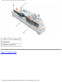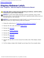
1
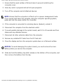
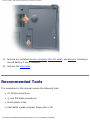
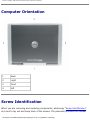
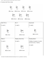
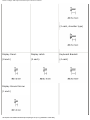
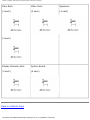
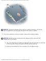
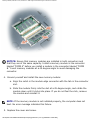
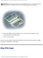
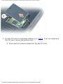
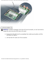
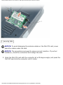
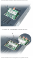
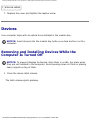
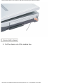
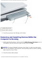
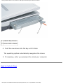
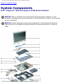
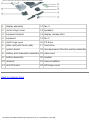
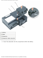
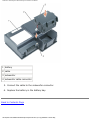
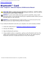
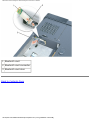
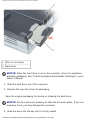
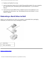
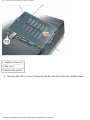
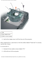
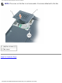
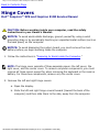
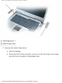
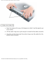
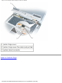
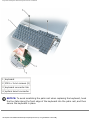
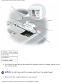
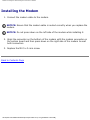
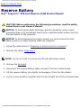
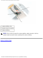
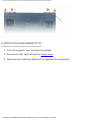
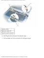
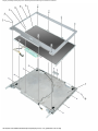
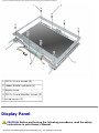
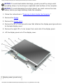
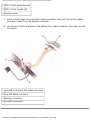
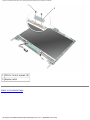
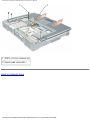
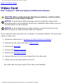
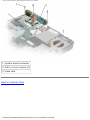
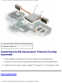
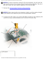
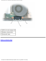
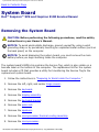
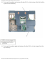
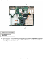
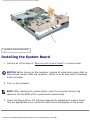
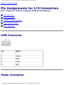
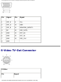
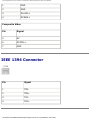
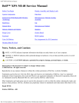
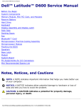
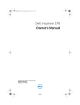
Dell Inspiron XPS and Inspiron 9100 Service Manual
Dell™ Inspiron™ XPS and Inspiron
9100 Service Manual
Before You Begin
Memory Module, Mini PCI Card, and Devices
System Components
Subwoofer
Bluetooth™ Card
Hard Drive
Fans
Hinge Covers
Keyboard
Modem
Reserve Battery
Display Assembly and Display Latch
Keyboard Bracket
Palm Rest
Video Card
Microprocessor Thermal-Cooling Assembly
Microprocessor Module
Speakers
Display Release Latch
System Board
Flashing the BIOS
Pin Assignments for I/O Connectors
Notes, Notices, and Cautions
NOTE: A NOTE indicates important information that helps you make better use
of your computer.
NOTICE: A NOTICE indicates either potential damage to hardware or loss of
data and tells you how to avoid the problem.
file:///F|/Service%20Manuals/Dell/Inspiron/xps/index.htm (1 of 2) [2/28/2004 7:48:16 AM]
Before You Begin: Dell Inspiron XPS and Inspiron 9100 Service Manual
Back to Contents Page
Before You Begin
Dell™ Inspiron™ XPS and Inspiron 9100 Service Manual
Preparing to Work Inside the Computer
Recommended Tools
Computer Orientation
Screw Identification
Preparing to Work Inside the Computer
CAUTION: Only a certified service technician should perform repairs on
your computer. Damage due to servicing that is not authorized by Dell
is not covered by your warranty. Read and follow the safety instructions
in the Owner's Manual that came with the computer.
CAUTION: To prevent static damage to components inside your
computer, discharge static electricity from your body before you touch
any of your computer's electronic components. You can do so by
touching an unpainted metal surface.
CAUTION: Handle components and cards with care. Do not touch the
components or contacts on a card. Hold a card by its edges or by its
metal mounting bracket. Hold a component such as a microprocessor by
its edges, not by its pins.
NOTICE: When you disconnect a cable, pull on its connector or on its strainrelief loop, not on the cable itself. Some cables have a connector with locking
tabs; if you are disconnecting this type of cable, press in on the locking tabs
before you disconnect the cable. As you pull connectors apart, keep them
evenly aligned to avoid bending any connector pins. Also, before you connect a
cable, ensure that both connectors are correctly oriented and aligned.
NOTICE: To avoid damaging the computer, perform the following steps before
you begin working inside the computer.
file:///F|/Service%20Manuals/Dell/Inspiron/xps/begin.htm (1 of 7) [2/28/2004 7:48:26 AM]
Before You Begin: Dell Inspiron XPS and Inspiron 9100 Service Manual
1. Ensure that the work surface is flat and clean to prevent scratching the
computer cover.
2. Save any work in progress and exit all open programs.
3. Turn off the computer and all attached devices.
NOTE: Ensure that the computer is off and not in a power management mode.
If you cannot shut down the computer using the computer operating system,
press and hold the power button for 4 seconds.
4. If the computer is connected to a docking device (docked), undock it.
5. Disconnect the computer from the electrical outlet.
6. To avoid possible damage to the system board, wait 10 to 20 seconds and then
disconnect any attached devices.
7. Disconnect all other external cables from the computer.
8. Remove any installed PC Cards from the PC Card slot.
9. Close the display and turn the computer upside down on a flat work surface.
NOTICE: To avoid damaging the system board, you must remove the main
battery before you service the computer.
10. Slide and hold the battery-bay latch release on the bottom of the computer, and
then remove the battery from the bay.
file:///F|/Service%20Manuals/Dell/Inspiron/xps/begin.htm (2 of 7) [2/28/2004 7:48:26 AM]
Before You Begin: Dell Inspiron XPS and Inspiron 9100 Service Manual
11. Remove any installed memory modules, Mini PCI cards, and devices, including a
second battery if one is installed.
12. Remove the hard drive.
Recommended Tools
The procedures in this manual require the following tools:
●
#1 Phillips screwdriver
●
¼-inch flat-blade screwdriver
●
Small plastic scribe
●
Flash BIOS update program floppy disk or CD
file:///F|/Service%20Manuals/Dell/Inspiron/xps/begin.htm (3 of 7) [2/28/2004 7:48:26 AM]
Before You Begin: Dell Inspiron XPS and Inspiron 9100 Service Manual
Computer Orientation
1
back
2
right
3
front
4
left
Screw Identification
When you are removing and replacing components, photocopy "Screw Identification"
as a tool to lay out and keep track of the screws. The placemat provides the number
file:///F|/Service%20Manuals/Dell/Inspiron/xps/begin.htm (4 of 7) [2/28/2004 7:48:26 AM]
Before You Begin: Dell Inspiron XPS and Inspiron 9100 Service Manual
of screws and their sizes.
Hard Drive:
Fan 2
Keyboard:
(1 each)
(1 each)
(2 each)
Modem:
Display Assembly:
Display Bezel:
(1 each)
(4 each)
(display bumpers, 6 each;
screw covers, 2 each)
(6 each)
file:///F|/Service%20Manuals/Dell/Inspiron/xps/begin.htm (5 of 7) [2/28/2004 7:48:26 AM]
Before You Begin: Dell Inspiron XPS and Inspiron 9100 Service Manual
(2 each, shoulder type)
Display Panel:
Display Latch:
Keyboard Bracket:
(8 each)
(2 each)
(4 each)
Display Ground Screw:
(1 each)
file:///F|/Service%20Manuals/Dell/Inspiron/xps/begin.htm (6 of 7) [2/28/2004 7:48:26 AM]
Before You Begin: Dell Inspiron XPS and Inspiron 9100 Service Manual
Palm Rest:
Video Card:
Speakers:
(3 each)
(4 each)
(3 each)
(4 each)
Display Release Latch:
System Board:
(2 each)
(6 each)
Back to Contents Page
file:///F|/Service%20Manuals/Dell/Inspiron/xps/begin.htm (7 of 7) [2/28/2004 7:48:26 AM]
Memory Module, Mini PCI Card, and Devices: Dell Inspiron XPS and Inspiron 9100 Service Manual
Back to Contents Page
Memory Module, Mini PCI Card, and
Devices
Dell™ Inspiron™ XPS and Inspiron 9100 Service Manual
Memory Module
Mini PCI Card
Devices
Memory Module
CAUTION: Before working inside your Dell™ computer, read the safety
instructions in your Owner's Manual.
CAUTION: To prevent static damage to components inside your
computer, discharge static electricity from your body before you touch
any of your computer's electronic components. You can do so by
touching an unpainted metal surface.
NOTE: Memory modules purchased from Dell are covered under your computer
warranty.
NOTE: This computer requires matched memory modules and therefore, it
always has two identical memory modules.
1. Follow the instructions in "Preparing to Work Inside the Computer."
2. Turn the computer over, loosen the captive screw (labeled "M") from the
memory module cover, and lift the cover.
file:///F|/Service%20Manuals/Dell/Inspiron/xps/upgrades.htm (1 of 14) [2/28/2004 7:48:28 AM]
Memory Module, Mini PCI Card, and Devices: Dell Inspiron XPS and Inspiron 9100 Service Manual
NOTICE: To prevent damage to the memory module connector, do not use
tools to spread the securing clips that secure the memory module.
3. If you are replacing a memory module, remove the existing module.
NOTICE: Handle memory modules by their edges, and do not touch the
components on a module.
a. Use your fingertips to carefully spread apart the securing clips on each end
of the memory module connector until the module pops up.
b. Remove the module from the connector at a 45-degree angle.
file:///F|/Service%20Manuals/Dell/Inspiron/xps/upgrades.htm (2 of 14) [2/28/2004 7:48:28 AM]
Memory Module, Mini PCI Card, and Devices: Dell Inspiron XPS and Inspiron 9100 Service Manual
NOTICE: Ensure that memory modules are installed in both connectors and
that they are of the same capacity. Install a memory module in the connector
labeled "DIMM A" before you install a module in the connector labeled "DIMM
B." Insert memory modules at a 45-degree angle to avoid damaging the
connector.
4. Ground yourself and install the new memory module:
a. Align the notch in the module edge connector with the tab in the connector
slot.
b. Slide the module firmly into the slot at a 45-degree angle, and rotate the
module down until it clicks into place. If you do not feel the click, remove
the module and reinstall it.
NOTE: If the memory module is not installed properly, the computer does not
boot. No error message indicates this failure.
5. Replace the cover and screw.
file:///F|/Service%20Manuals/Dell/Inspiron/xps/upgrades.htm (3 of 14) [2/28/2004 7:48:28 AM]
Memory Module, Mini PCI Card, and Devices: Dell Inspiron XPS and Inspiron 9100 Service Manual
NOTICE: If the memory module cover is difficult to close, remove the module
and reinstall it. Forcing the cover to close may damage your computer.
6. Insert the battery into the battery bay, or connect the AC adapter to your
computer and an electrical outlet.
7. Turn on the computer.
As the computer boots, it detects the additional memory and automatically updates
the system configuration information.
Mini PCI Card
file:///F|/Service%20Manuals/Dell/Inspiron/xps/upgrades.htm (4 of 14) [2/28/2004 7:48:28 AM]
Memory Module, Mini PCI Card, and Devices: Dell Inspiron XPS and Inspiron 9100 Service Manual
CAUTION: FCC rules strictly prohibit users from installing 5-GHz
(802.11a,802.11a/b, 802.11a/b/g) Wireless LAN Mini PCI cards. Under
no circumstances should you install such a device. Only trained Dell
service personnel are authorized to install a 5-GHz Wireless LAN Mini
PCI card.
CAUTION: If you are removing and/or installing a 2.4-GHz (802.11b,
802.11b/g) Mini PCI card, follow the instructions noted below. Only
products approved for use in your portable computer may be installed.
Approved Mini PCI cards may be purchased only from Dell.
CAUTION: Before working inside your computer, read the safety
instructions in your Owner's Manual.
NOTICE: To avoid damaging the system board, you must remove the main
battery before you begin working inside the computer.
NOTE: 2.4-GHz Wireless LAN PC Cards may be removed and installed by the
user.
If you ordered a Mini PCI card with your computer, the card is already installed.
1. Follow the instructions in "Preparing to Work Inside the Computer."
2. Turn over the computer.
3. Unscrew the captive screw labeled "C" and remove the Mini PCI card cover.
file:///F|/Service%20Manuals/Dell/Inspiron/xps/upgrades.htm (5 of 14) [2/28/2004 7:48:28 AM]
Memory Module, Mini PCI Card, and Devices: Dell Inspiron XPS and Inspiron 9100 Service Manual
4. If a Mini PCI card is not already installed, go to step 5. If you are replacing a
Mini PCI card, remove the existing card:
a. Disconnect the antenna cables from the Mini PCI card.
file:///F|/Service%20Manuals/Dell/Inspiron/xps/upgrades.htm (6 of 14) [2/28/2004 7:48:28 AM]
Memory Module, Mini PCI Card, and Devices: Dell Inspiron XPS and Inspiron 9100 Service Manual
1 antenna cables (2)
NOTICE: To prevent damage to the Mini PCI card connector, do not use tools to
spread the securing clips that secure the card.
b. Release the Mini PCI card by spreading the metal securing tabs until the
card pops up slightly.
c. Lift the Mini PCI card out of its connector.
file:///F|/Service%20Manuals/Dell/Inspiron/xps/upgrades.htm (7 of 14) [2/28/2004 7:48:28 AM]
Memory Module, Mini PCI Card, and Devices: Dell Inspiron XPS and Inspiron 9100 Service Manual
1 securing tabs
NOTICE: To avoid damaging the antenna cables or the Mini PCI card, never
place the cables under the card.
NOTICE: The connectors are keyed to ensure correct insertion. If you feel
resistance, check the connectors and realign the card.
5. Align the Mini PCI card with the connector at a 45-degree angle, and press the
Mini PCI card into the connector until it clicks.
file:///F|/Service%20Manuals/Dell/Inspiron/xps/upgrades.htm (8 of 14) [2/28/2004 7:48:28 AM]
Memory Module, Mini PCI Card, and Devices: Dell Inspiron XPS and Inspiron 9100 Service Manual
6. Connect the antenna cables to the Mini PCI card.
file:///F|/Service%20Manuals/Dell/Inspiron/xps/upgrades.htm (9 of 14) [2/28/2004 7:48:28 AM]
Memory Module, Mini PCI Card, and Devices: Dell Inspiron XPS and Inspiron 9100 Service Manual
1 antenna cables
7. Replace the cover and tighten the captive screw.
Devices
Your computer ships with an optical drive installed in the module bay.
NOTICE: Insert devices into the module bay before you dock and turn on the
computer.
Removing and Installing Devices While the
Computer Is Turned Off
NOTICE: To prevent damage to devices, store them in a safe, dry place when
they are not installed in the computer. Avoid pressing down on them or placing
heavy objects on top of them.
1. Press the device latch release.
The latch release ejects partway.
file:///F|/Service%20Manuals/Dell/Inspiron/xps/upgrades.htm (10 of 14) [2/28/2004 7:48:28 AM]
Memory Module, Mini PCI Card, and Devices: Dell Inspiron XPS and Inspiron 9100 Service Manual
1 device latch release
2. Pull the device out of the module bay.
file:///F|/Service%20Manuals/Dell/Inspiron/xps/upgrades.htm (11 of 14) [2/28/2004 7:48:28 AM]
Memory Module, Mini PCI Card, and Devices: Dell Inspiron XPS and Inspiron 9100 Service Manual
1 module bay device
2 device latch release
3. Push the new device into the bay until it clicks.
Removing and Installing Devices While the
Computer Is Running
1. Before ejecting the device, double-click the Safely Remove Hardware icon on
the taskbar, click the device you want to eject, and click Stop.
NOTICE: To prevent damage to devices, store them in a safe, dry place when
they are not installed in the computer. Avoid pressing down on them or placing
heavy objects on top of them.
2. Press the device latch release.
file:///F|/Service%20Manuals/Dell/Inspiron/xps/upgrades.htm (12 of 14) [2/28/2004 7:48:28 AM]
Memory Module, Mini PCI Card, and Devices: Dell Inspiron XPS and Inspiron 9100 Service Manual
1 device latch release
3. Pull the device out of the module bay.
file:///F|/Service%20Manuals/Dell/Inspiron/xps/upgrades.htm (13 of 14) [2/28/2004 7:48:28 AM]
Memory Module, Mini PCI Card, and Devices: Dell Inspiron XPS and Inspiron 9100 Service Manual
1 module bay device
2 device latch release
4. Push the new device into the bay until it clicks.
The operating system automatically recognizes the device.
5. If necessary, enter your password to unlock your computer.
Back to Contents Page
file:///F|/Service%20Manuals/Dell/Inspiron/xps/upgrades.htm (14 of 14) [2/28/2004 7:48:28 AM]
System Components: Dell Inspiron XPS and Inspiron 9100 Service Manual
Back to Contents Page
System Components
Dell™ Inspiron™ XPS and Inspiron 9100 Service Manual
NOTICE: Only a certified service technician should perform repairs on your
computer. Damage due to servicing that is not authorized by Dell is not covered
by your warranty.
NOTICE: Unless otherwise noted, each procedure in this document assumes
that a part can be replaced by performing the removal procedure in reverse
order.
file:///F|/Service%20Manuals/Dell/Inspiron/xps/system.htm (1 of 2) [2/28/2004 7:48:29 AM]
System Components: Dell Inspiron XPS and Inspiron 9100 Service Manual
1
display assembly
12 fan 3
2
center hinge cover
13 speakers
3
keyboard bracket
14 display release latch
4
keyboard
15 fan 2
5
right hinge cover
16 CD drive
6
palm rest (with touch pad)
17 hard drive
7
system board
18 microprocessor thermal-cooling assembly
8
battery and subwoofer assembly 19 video card
9
bottom assembly
20 modem
10 memory
21 reserve battery
11 mini PCI card
22 left hinge cover
Back to Contents Page
file:///F|/Service%20Manuals/Dell/Inspiron/xps/system.htm (2 of 2) [2/28/2004 7:48:29 AM]
Subwoofer: Dell Inspiron XPS and Inspiron 9100 Service Manual
Back to Contents Page
Subwoofer
Dell™ Inspiron™ XPS and Inspiron 9100 Service Manual
CAUTION: Before performing the following procedures, read the safety
instructions in your Owner's Manual.
NOTICE: To avoid electrostatic discharge, ground yourself by using a wrist
grounding strap or by periodically touching an unpainted metal surface (such as
the back panel) on the computer.
If you ordered a subwoofer with your computer, it is already installed. To remove and
replace a subwoofer:
1. Follow the instructions in "Preparing to Work Inside the Computer."
2. Remove the battery.
NOTICE: To avoid damaging the system board, you must remove the main
battery before you begin working inside the computer.
3. Remove the subwoofer from the battery:
a. Disconnect the subwoofer cable.
b. Use a small screwdriver or scribe to release the subwoofer from the
compartment in the battery.
file:///F|/Service%20Manuals/Dell/Inspiron/xps/woofer.htm (1 of 3) [2/28/2004 7:48:29 AM]
Subwoofer: Dell Inspiron XPS and Inspiron 9100 Service Manual
1 battery
2 cable
3 subwoofer
4 subwoofer cable connector
4. Insert the subwoofer into the compartment within the battery.
file:///F|/Service%20Manuals/Dell/Inspiron/xps/woofer.htm (2 of 3) [2/28/2004 7:48:29 AM]
Subwoofer: Dell Inspiron XPS and Inspiron 9100 Service Manual
1 battery
2 cable
3 subwoofer
4 subwoofer cable connector
5. Connect the cable to the subwoofer connector.
6. Replace the battery in the battery bay.
Back to Contents Page
file:///F|/Service%20Manuals/Dell/Inspiron/xps/woofer.htm (3 of 3) [2/28/2004 7:48:29 AM]
Bluetooth Card: Dell Inspiron XPS and Inspiron 9100 Service Manual
Back to Contents Page
Bluetooth™ Card
Dell™ Inspiron™ XPS and Inspiron 9100 Service Manual
CAUTION: Before performing the following procedures, read the safety
instructions in your Owner's Manual.
NOTICE: To avoid electrostatic discharge, ground yourself by using a wrist
grounding strap or by periodically touching an unpainted metal surface (such as
the back panel) on the computer.
NOTICE: To avoid damaging the system board, you must remove the main
battery before you begin working inside the computer.
If you ordered a Bluetooth card with your computer, the card is already installed.
1. Follow the instructions in "Preparing to Work Inside the Computer."
2. Remove the battery.
3. Open the Bluetooth card door.
4. Using a plastic scribe or screwdriver, gently pry the Bluetooth card from the
plastic guide bracket and the compartment so that you can disconnect the
Bluetooth card from its cable and remove it from the computer.
file:///F|/Service%20Manuals/Dell/Inspiron/xps/blue.htm (1 of 2) [2/28/2004 7:48:30 AM]
Bluetooth Card: Dell Inspiron XPS and Inspiron 9100 Service Manual
1 Bluetooth card
2 Bluetooth card connector
3 Bluetooth card door
Back to Contents Page
file:///F|/Service%20Manuals/Dell/Inspiron/xps/blue.htm (2 of 2) [2/28/2004 7:48:30 AM]
Hard Drive: Dell Inspiron XPS and Inspiron 9100 Service Manual
Back to Contents Page
Hard Drive
Dell™ Inspiron™ XPS and Inspiron 9100 Service Manual
CAUTION: If you remove the hard drive from the computer when the
drive is hot, do not touch the metal housing of the hard drive.
CAUTION: Before working inside your computer, read the safety
instructions in your Owner's Manual.
NOTICE: To avoid damaging the system board, you must remove the main
battery before you begin working inside the computer.
NOTICE: To prevent data loss, turn off your computer before removing the
hard drive. Do not remove the hard drive while the computer is on, in standby
mode, or in hibernate mode.
NOTICE: Hard drives are extremely fragile; even a slight bump can damage the
drive.
NOTE: Dell does not guarantee compatibility or provide support for hard drives
from sources other than Dell.
NOTE: You need the Operating System CD to install the Microsoft® Windows®
operating system. You also need the Drivers and Utilities CD for your computer
to install the drivers and utilities on the new hard drive.
1. Follow the instructions in "Preparing to Work Inside the Computer."
2. Turn over the computer and remove the M3 x 3-mm screw.
file:///F|/Service%20Manuals/Dell/Inspiron/xps/hdd.htm (1 of 3) [2/28/2004 7:48:31 AM]
Hard Drive: Dell Inspiron XPS and Inspiron 9100 Service Manual
1
M3 x 3-mm screw
2
hard drive
NOTICE: When the hard drive is not in the computer, store it in protective
antistatic packaging. See "Protecting Against Electrostatic Discharge" in your
Owner's Manual.
3. Slide the hard drive out of the computer.
4. Remove the new drive from its packaging.
Save the original packaging for storing or shipping the hard drive.
NOTICE: Use firm and even pressure to slide the drive into place. If you use
excessive force, you may damage the connector.
5. Slide the drive into the bay until it is fully seated.
file:///F|/Service%20Manuals/Dell/Inspiron/xps/hdd.htm (2 of 3) [2/28/2004 7:48:31 AM]
Hard Drive: Dell Inspiron XPS and Inspiron 9100 Service Manual
6. Replace and tighten the screw.
7. Use the Operating System CD to install the operating system for your computer.
For instructions, see "Reinstalling Microsoft Windows XP" in your Owner's
Manual.
8. Use the Drivers and Utilities CD to install the drivers and utilities for your
computer. For instructions, see "Reinstalling Drivers and Utilities" in your
Owner's Manual.
Returning a Hard Drive to Dell
Return your old hard drive to Dell in its original or comparable foam packaging.
Otherwise, the hard drive may be damaged in transit.
1
hard drive
2
foam packaging
Back to Contents Page
file:///F|/Service%20Manuals/Dell/Inspiron/xps/hdd.htm (3 of 3) [2/28/2004 7:48:31 AM]
Fans: Dell Inspiron XPS and Inspiron 9100 Service Manual
Back to Contents Page
Fans
Dell™ Inspiron™ XPS and Inspiron 9100 Service Manual
CAUTION: Before performing the following procedures, read the safety
instructions in your Owner's Manual.
NOTICE: To avoid electrostatic discharge, ground yourself by using a wrist
grounding strap or by periodically touching an unpainted metal surface (such as
the back panel) on the computer.
NOTICE: To avoid damaging the system board, you must remove the main
battery before you begin working inside the computer.
The two fans are located on the bottom of the computer, one with screws labeled "F2"
(fan 2) and one with screws labeled "F3" (fan 3).
To remove fan 2:
1. Follow the instructions in "Preparing to Work Inside the Computer."
2. Turn over the computer.
3. Unscrew the two captive screws labeled "F2," lift up the fan cover, and remove it
from the computer.
NOTE: This fan cover comes off over the audio connectors.
file:///F|/Service%20Manuals/Dell/Inspiron/xps/fan.htm (1 of 4) [2/28/2004 7:48:32 AM]
Fans: Dell Inspiron XPS and Inspiron 9100 Service Manual
1 captive screws (2)
2 fan cover
3 audio connectors
4. Remove the M2.5 x 6-mm screw on the fan and lift up the fan release lever.
file:///F|/Service%20Manuals/Dell/Inspiron/xps/fan.htm (2 of 4) [2/28/2004 7:48:32 AM]
Fans: Dell Inspiron XPS and Inspiron 9100 Service Manual
1 fan
2 fan release lever
3 M2.5 x 6-mm screw
5. Use the fan release lever to lift the fan out of the computer.
When replacing fan 2, press down on the fan surface labeled "Press here" to securely
seat the fan in place.
To remove fan 3:
1. Unscrew the two captive screws labeled "F3."
2. Lift the fan out of the computer.
file:///F|/Service%20Manuals/Dell/Inspiron/xps/fan.htm (3 of 4) [2/28/2004 7:48:32 AM]
Fans: Dell Inspiron XPS and Inspiron 9100 Service Manual
NOTE: The cover on this fan is not removable. It remains attached to the fan.
1 captive screws (2)
2 fan cover
Back to Contents Page
file:///F|/Service%20Manuals/Dell/Inspiron/xps/fan.htm (4 of 4) [2/28/2004 7:48:32 AM]
Hinge Covers: Dell Inspiron XPS and Inspiron 9100 Service Manual
Back to Contents Page
Hinge Covers
Dell™ Inspiron™ XPS and Inspiron 9100 Service Manual
CAUTION: Before working inside your computer, read the safety
instructions in your Owner's Manual.
NOTICE: To avoid electrostatic discharge, ground yourself by using a wrist
grounding strap or by periodically touching an unpainted metal surface (such as
the back panel) on the computer.
NOTICE: To avoid damaging the system board, you must remove the main
battery before you begin working inside the computer.
1. Follow the instructions in "Preparing to Work Inside the Computer."
NOTE: The hinge cover consists of three separate pieces: the left cover, the
right cover, and the center cover. To remove computer components, you must
remove all three covers except for when removing the keyboard or the reserve
battery. For these two components, remove only the center cover.
2. Remove the left and right hinge covers:
a. Open the display.
b. Slide the left and right hinge covers forward (toward the back of the
computer) and then slide them to the side, away from the computer.
file:///F|/Service%20Manuals/Dell/Inspiron/xps/hinge.htm (1 of 4) [2/28/2004 7:48:33 AM]
Hinge Covers: Dell Inspiron XPS and Inspiron 9100 Service Manual
1 left hinge cover
2 right hinge cover
3. Remove the center hinge cover:
a. Close the display.
b. Facing the front of the computer, press in on the two hinge cover snaps
and pull them up slightly to disengage them.
file:///F|/Service%20Manuals/Dell/Inspiron/xps/hinge.htm (2 of 4) [2/28/2004 7:48:33 AM]
Hinge Covers: Dell Inspiron XPS and Inspiron 9100 Service Manual
1 hinge cover snaps (2)
c. Open the display all the way (180 degrees) so that it lies flat against your
work surface.
d. Lift the center hinge cover just enough to access the flex-cable connector.
e. Using the pull-tab, disconnect the center–hinge-cover flex cable from the
system board connector.
file:///F|/Service%20Manuals/Dell/Inspiron/xps/hinge.htm (3 of 4) [2/28/2004 7:48:33 AM]
Hinge Covers: Dell Inspiron XPS and Inspiron 9100 Service Manual
1 center hinge cover
2 center–hinge-cover flex cable and pull-tab
3 system board connector
Back to Contents Page
file:///F|/Service%20Manuals/Dell/Inspiron/xps/hinge.htm (4 of 4) [2/28/2004 7:48:33 AM]
Keyboard: Dell Inspiron XPS and Inspiron 9100 Service Manual
Back to Contents Page
Keyboard
Dell™ Inspiron™ XPS and Inspiron 9100 Service Manual
CAUTION: Before performing the following procedures, read the safety
instructions in your Owner's Manual.
NOTICE: To avoid electrostatic discharge, ground yourself by using a wrist
grounding strap or by periodically touching an unpainted metal surface (such as
the back panel) on the computer.
NOTICE: To avoid damaging the system board, you must remove the main
battery before you begin working inside the computer.
1. Follow the instructions in "Preparing to Work Inside the Computer."
2. Open the display.
3. Remove the center hinge cover.
NOTE: You do not need to remove the left and right hinge covers.
4. Remove the keyboard:
a. Remove the two M2.5 x 3-mm screws across the top of the keyboard.
NOTICE: The keycaps on the keyboard are fragile, easily dislodged, and timeconsuming to replace. Be careful when removing and handling the keyboard.
b. Lift up the keyboard and gently slide it toward the display.
c. Hold the keyboard up and slightly forward to allow access to the keyboard
connector.
d. Pull up on the keyboard connector tab to disconnect the keyboard
connector from the system board.
file:///F|/Service%20Manuals/Dell/Inspiron/xps/keyboard.htm (1 of 3) [2/28/2004 7:48:34 AM]
Keyboard: Dell Inspiron XPS and Inspiron 9100 Service Manual
1 keyboard
2 M2.5 x 3-mm screws (2)
3 keyboard connector tab
4 system board connector
NOTICE: To avoid scratching the palm rest when replacing the keyboard, hook
the four tabs along the front edge of the keyboard into the palm rest, and then
secure the keyboard in place.
file:///F|/Service%20Manuals/Dell/Inspiron/xps/keyboard.htm (2 of 3) [2/28/2004 7:48:34 AM]
Keyboard: Dell Inspiron XPS and Inspiron 9100 Service Manual
Back to Contents Page
file:///F|/Service%20Manuals/Dell/Inspiron/xps/keyboard.htm (3 of 3) [2/28/2004 7:48:34 AM]
Modem: Dell Inspiron XPS and Inspiron 9100 Service Manual
Back to Contents Page
Modem
Dell™ Inspiron™ XPS and Inspiron 9100 Service Manual
CAUTION: Before performing the following procedures, read the safety
instructions in your Owner's Manual.
NOTICE: To avoid electrostatic discharge, ground yourself by using a wrist
grounding strap or by periodically touching an unpainted metal surface (such as
the back panel) on the computer.
NOTICE: To avoid damaging the system board, you must remove the main
battery before you begin working inside the computer.
Removing the Modem
1. Follow the instructions in "Preparing to Work Inside the Computer."
2. Remove the left, right, and center hinge covers.
3. Remove the keyboard.
4. Remove the M2.5 x 3-mm screw.
file:///F|/Service%20Manuals/Dell/Inspiron/xps/modem.htm (1 of 3) [2/28/2004 7:48:35 AM]
Modem: Dell Inspiron XPS and Inspiron 9100 Service Manual
1 M2.5 x 3-mm screw
2 pull-tab
3 modem
4 modem cable
5. Pull up on the pull-tab to disconnect the modem from the modem connector on
the system board.
NOTICE: Do not disconnect the modem cable from the system board.
6. Disconnect the modem cable from the modem.
file:///F|/Service%20Manuals/Dell/Inspiron/xps/modem.htm (2 of 3) [2/28/2004 7:48:35 AM]
Modem: Dell Inspiron XPS and Inspiron 9100 Service Manual
Installing the Modem
1. Connect the modem cable to the modem.
NOTICE: Ensure that the modem cable is routed correctly when you replace the
modem.
NOTICE: Do not press down on the left side of the modem while installing it.
2. Align the connector on the bottom of the modem with the modem connector on
the system board and then press down on the right side of the modem to seat
both connectors.
3. Replace the M2.5 x 3-mm screw.
Back to Contents Page
file:///F|/Service%20Manuals/Dell/Inspiron/xps/modem.htm (3 of 3) [2/28/2004 7:48:35 AM]
Reserve Battery: Dell Inspiron XPS and Inspiron 9100 Service Manual
Back to Contents Page
Reserve Battery
Dell™ Inspiron™ XPS and Inspiron 9100 Service Manual
CAUTION: Before performing the following procedures, read the safety
instructions in your Owner's Manual.
NOTICE: To avoid electrostatic discharge, ground yourself by using a wrist
grounding strap or by periodically touching an unpainted metal surface (such as
the back panel) on the computer.
NOTICE: To avoid damaging the system board, you must remove the main
battery before you begin working inside the computer.
1. Follow the instructions in "Preparing to Work Inside the Computer."
2. Remove the center hinge cover.
NOTE: You do not need to remove the left and right hinge covers.
3. Remove the keyboard.
4. Disconnect the reserve battery cable connector from the system board.
5. Lift the reserve battery clip slightly to disengage it from the fan chassis.
6. Pull the reserve battery together with the clip straight out of the computer base.
file:///F|/Service%20Manuals/Dell/Inspiron/xps/reserve.htm (1 of 2) [2/28/2004 7:48:35 AM]
Reserve Battery: Dell Inspiron XPS and Inspiron 9100 Service Manual
1 reserve battery clip
2 system board connector
3 reserve battery
NOTE: Use a scribe to press the reserve battery cable connector into the
system board connector when replacing the reserve battery.
Back to Contents Page
file:///F|/Service%20Manuals/Dell/Inspiron/xps/reserve.htm (2 of 2) [2/28/2004 7:48:35 AM]
Display Assembly and Display Latch: Dell Inspiron XPS and Inspiron 9100 Service Manual
Back to Contents Page
Display Assembly and Display Latch
Dell™ Inspiron™ XPS and Inspiron 9100 Service Manual
Display Bezel
Display Panel
Display Latch
CAUTION: Before performing the following procedures, read the safety
instructions in your Owner's Manual.
NOTICE: To avoid electrostatic discharge, ground yourself by using a wrist
grounding strap or by periodically touching an unpainted metal surface (such as
the back panel) on the computer.
NOTICE: To avoid damaging the system board, you must remove the main
battery before you begin working inside the computer.
1. Follow the instructions in "Preparing to Work Inside the Computer."
NOTICE: Before turning the computer over and removing the screws, ensure that
the display is firmly latched closed.
2. Turn the computer over and remove the four screws (two on each side) labeled
"D" on the bottom of the computer.
file:///F|/Service%20Manuals/Dell/Inspiron/xps/display.htm (1 of 11) [2/28/2004 7:48:37 AM]
Display Assembly and Display Latch: Dell Inspiron XPS and Inspiron 9100 Service Manual
1 M2.5 x 6-mm screws labeled "D" (4)
3. Turn the computer over and open the display.
4. Remove the left, right, and center hinge covers.
5. Disconnect the antenna cables (pull to separate the connectors).
file:///F|/Service%20Manuals/Dell/Inspiron/xps/display.htm (2 of 11) [2/28/2004 7:48:37 AM]
Display Assembly and Display Latch: Dell Inspiron XPS and Inspiron 9100 Service Manual
1 display cable
2 antenna cables (2)
3 system board connector
6. Use the pull-tab to disconnect the display cable.
7. Lift the display out of the computer at a 90-degree angle.
file:///F|/Service%20Manuals/Dell/Inspiron/xps/display.htm (3 of 11) [2/28/2004 7:48:37 AM]
Display Assembly and Display Latch: Dell Inspiron XPS and Inspiron 9100 Service Manual
1 display
Display
file:///F|/Service%20Manuals/Dell/Inspiron/xps/display.htm (4 of 11) [2/28/2004 7:48:37 AM]
Display Assembly and Display Latch: Dell Inspiron XPS and Inspiron 9100 Service Manual
file:///F|/Service%20Manuals/Dell/Inspiron/xps/display.htm (5 of 11) [2/28/2004 7:48:37 AM]
Display Assembly and Display Latch: Dell Inspiron XPS and Inspiron 9100 Service Manual
1 M2.5 x 6-mm screws (6)
5 display bezel
2 rubber display bumpers (6)
6 display panel
3 M2.5 x 6-mm shoulder screws (2) 7 display base
4 screw covers (2)
8 M2.5 x 3-mm screws (8)
Display Bezel
CAUTION: Before performing the following procedures, read the safety
instructions in your Owner's Manual.
NOTICE: To avoid electrostatic discharge, ground yourself by using a wrist
grounding strap or by periodically touching an unpainted metal surface (such as
the back panel) on the computer.
NOTICE: To avoid damaging the system board, you must remove the main
battery before you begin working inside the computer.
1. Follow the instructions in "Preparing to Work Inside the Computer."
2. Remove the display.
3. Remove the six rubber display bumpers and two screw covers.
4. Remove the six M2.5 x 6-mm screws and two M2.5 x 6-mm shoulder screws and
remove the display bezel.
file:///F|/Service%20Manuals/Dell/Inspiron/xps/display.htm (6 of 11) [2/28/2004 7:48:37 AM]
Display Assembly and Display Latch: Dell Inspiron XPS and Inspiron 9100 Service Manual
1 M2.5 x 6-mm screws (6)
2 rubber display bumpers (6)
3 display bezel
4 M2.5 x 6-mm shoulder screws (2)
5 screw covers (2)
Display Panel
CAUTION: Before performing the following procedures, read the safety
instructions in your Owner's Manual.
file:///F|/Service%20Manuals/Dell/Inspiron/xps/display.htm (7 of 11) [2/28/2004 7:48:37 AM]
Display Assembly and Display Latch: Dell Inspiron XPS and Inspiron 9100 Service Manual
NOTICE: To avoid electrostatic discharge, ground yourself by using a wrist
grounding strap or by touching an unpainted metal surface on the computer.
NOTICE: To avoid damaging the system board, you must remove the main
battery before you begin working inside the computer.
1. Follow the instructions in "Preparing to Work Inside the Computer."
2. Remove the display.
3. Remove the display bezel.
4. Remove the M2 x 3-mm ground screw that attaches the display-panel ground wire
to the back display cover.
5. Remove the eight M2 x 3-mm screws from each side of the display panel.
6. Lift the display panel out of the display cover.
1 display-panel ground wire
file:///F|/Service%20Manuals/Dell/Inspiron/xps/display.htm (8 of 11) [2/28/2004 7:48:37 AM]
Display Assembly and Display Latch: Dell Inspiron XPS and Inspiron 9100 Service Manual
2 M2 x 3-mm ground screw
3 M2 x 3-mm screws (8)
4 display panel
7. Press in both sides of the top flex-cable connector, and pull the top flex-cable
connector away from the display connector.
8. Use the pull-tab to disconnect the bottom flex-cable connector from the inverter
connector.
1 pull-tab on bottom flex-cable connector
2 top flex-cable connector
3 display connector
4 inverter connector
file:///F|/Service%20Manuals/Dell/Inspiron/xps/display.htm (9 of 11) [2/28/2004 7:48:37 AM]
Display Assembly and Display Latch: Dell Inspiron XPS and Inspiron 9100 Service Manual
Display Latch
CAUTION: Before performing the following procedures, read the safety
instructions in your Owner's Manual.
NOTICE: To avoid electrostatic discharge, ground yourself by using a wrist
grounding strap or by touching an unpainted metal surface on the computer.
NOTICE: To avoid damaging the system board, you must remove the main
battery before you begin working inside the computer.
1. Follow the instructions in "Preparing to Work Inside the Computer."
2. Remove the display.
3. Remove the display bezel.
4. Remove the two M2.5 x 4-mm screws and remove the display latch.
file:///F|/Service%20Manuals/Dell/Inspiron/xps/display.htm (10 of 11) [2/28/2004 7:48:37 AM]
Display Assembly and Display Latch: Dell Inspiron XPS and Inspiron 9100 Service Manual
1 M2.5 x 4-mm screws (2)
2 display latch
Back to Contents Page
file:///F|/Service%20Manuals/Dell/Inspiron/xps/display.htm (11 of 11) [2/28/2004 7:48:37 AM]
Keyboard Bracket: Dell Inspiron XPS and Inspiron 9100 Service Manual
Back to Contents Page
Keyboard Bracket
Dell™ Inspiron™ XPS and Inspiron 9100 Service Manual
CAUTION: Before performing the following procedures, read the safety
instructions in your Owner's Manual.
NOTICE: To avoid electrostatic discharge, ground yourself by using a wrist
grounding strap or by periodically touching an unpainted metal surface (such as
the back panel) on the computer.
NOTICE: To avoid damaging the system board, you must remove the main
battery before you begin working inside the computer.
1. Follow the instructions in "Preparing to Work Inside the Computer."
2. Remove the left, right, and center hinge covers.
3. Remove the keyboard.
4. Remove the display assembly.
5. Remove the four M2.5 x 6-mm screws.
6. Pull up on the pull-tab on the FPC cable connector to disconnect the FPC cable
from the keyboard bracket
7. Slightly lift up the keyboard bracket, move it approximately one inch toward the
back of the computer, and then lift straight up to remove it.
file:///F|/Service%20Manuals/Dell/Inspiron/xps/keybrack.htm (1 of 2) [2/28/2004 7:48:38 AM]
Keyboard Bracket: Dell Inspiron XPS and Inspiron 9100 Service Manual
1 FPC cable pull-tab
2 M2.5 x 6-mm screws (4)
3 keyboard bracket
Back to Contents Page
file:///F|/Service%20Manuals/Dell/Inspiron/xps/keybrack.htm (2 of 2) [2/28/2004 7:48:38 AM]
Palm Rest: Dell Inspiron XPS and Inspiron 9100 Service Manual
Back to Contents Page
Palm Rest
Dell™ Inspiron™ XPS and Inspiron 9100 Service Manual
CAUTION: Before performing the following procedures, read the safety
instructions in your Owner's Manual.
NOTICE: To avoid electrostatic discharge, ground yourself by using a wrist
grounding strap or by periodically touching an unpainted metal surface (such as
the back panel) on the computer.
NOTICE: To avoid damaging the system board, you must remove the main
battery before you begin working inside the computer.
1. Follow the instructions in "Preparing to Work Inside the Computer."
2. Remove the left, right, and center hinge covers.
3. Remove the keyboard.
4. Remove the display assembly.
5. Remove the keyboard bracket.
6. Turn over the computer and remove the three M2.5 x 8-mm screws labeled "P."
file:///F|/Service%20Manuals/Dell/Inspiron/xps/palmrest.htm (1 of 3) [2/28/2004 7:48:38 AM]
Palm Rest: Dell Inspiron XPS and Inspiron 9100 Service Manual
1 M2.5 x 8-mm screws labeled "P" (3)
7. Turn the computer top-side up and remove the four M2.5 x 6-mm screws
labeled "P."
8. Disconnect the touch-pad connector from the system board.
9. Slide the palm rest forward and remove it from the computer.
file:///F|/Service%20Manuals/Dell/Inspiron/xps/palmrest.htm (2 of 3) [2/28/2004 7:48:38 AM]
Palm Rest: Dell Inspiron XPS and Inspiron 9100 Service Manual
1 M2.5 x 6-mm screws (4)
2 touch-pad connector
Back to Contents Page
file:///F|/Service%20Manuals/Dell/Inspiron/xps/palmrest.htm (3 of 3) [2/28/2004 7:48:38 AM]
Video Card: Dell Inspiron XPS and Inspiron 9100 Service Manual
Back to Contents Page
Video Card
Dell™ Inspiron™ XPS and Inspiron 9100 Service Manual
CAUTION: Before performing the following procedures, read the safety
instructions in your Owner's Manual.
NOTICE: To avoid electrostatic discharge, ground yourself by using a wrist
grounding strap or by periodically touching an unpainted metal surface (such as
the back panel) on the computer.
NOTICE: To avoid damaging the system board, you must remove the main
battery before you begin working inside the computer.
If you ordered a video card with your computer, it is already installed. To remove and
replace a video card:
1. Follow the instructions in "Preparing to Work Inside the Computer."
2. Remove the left, right, and center hinge covers.
3. Remove the keyboard.
4. Remove the display assembly.
5. Remove the keyboard bracket.
6. Remove the four M2.5 x 6-mm screws from the video card.
7. Gently pull up the video card to remove it.
The video card heat sink is part of the video card assembly.
file:///F|/Service%20Manuals/Dell/Inspiron/xps/video.htm (1 of 2) [2/28/2004 7:48:39 AM]
Video Card: Dell Inspiron XPS and Inspiron 9100 Service Manual
1 system board connector
2 M2.5 x 6-mm screws (4)
3 video card
Back to Contents Page
file:///F|/Service%20Manuals/Dell/Inspiron/xps/video.htm (2 of 2) [2/28/2004 7:48:39 AM]
Microprocessor Thermal-Cooling Assembly: Dell Inspiron XPS and Inspiron 9100 Service Manual
Back to Contents Page
Microprocessor Thermal-Cooling
Assembly
Dell™ Inspiron™ XPS and Inspiron 9100 Service Manual
Removing the Microprocessor Thermal-Cooling
Assembly
CAUTION: Before performing the following procedures, read the safety
instructions in your Owner's Manual.
NOTICE: To avoid electrostatic discharge, ground yourself by using a wrist
grounding strap or by periodically touching an unpainted metal surface (such as
the back panel) on the computer.
NOTICE: To avoid damaging the system board, you must remove the main
battery before you begin working inside the computer.
1. Follow the instructions in "Preparing to Work Inside the Computer."
2. Remove the left, right, and center hinge covers.
3. Remove the keyboard.
4. Remove the display assembly.
5. Remove the keyboard bracket.
6. Remove the video card.
7. Loosen in consecutive order the four captive screws, labeled "1" through "4,"
that secure the microprocessor thermal-cooling assembly to the system board.
8. Lift up the microprocessor thermal-cooling assembly and remove it from the
system board.
file:///F|/Service%20Manuals/Dell/Inspiron/xps/thermal.htm (1 of 2) [2/28/2004 7:48:40 AM]
Microprocessor Thermal-Cooling Assembly: Dell Inspiron XPS and Inspiron 9100 Service Manual
1 microprocessor thermal-cooling assembly
2 captive screws (4)
Installing the Microprocessor Thermal-Cooling
Assembly
1. Evenly apply thermal grease to the top surface of the microprocessor.
2. Place the microprocessor thermal-cooling assembly over the microprocessor.
3. Tighten the four captive screws, labeled "1" through "4," in consecutive order.
Back to Contents Page
file:///F|/Service%20Manuals/Dell/Inspiron/xps/thermal.htm (2 of 2) [2/28/2004 7:48:40 AM]
Microprocessor Module: Dell Inspiron XPS and Inspiron 9100 Service Manual
Back to Contents Page
Microprocessor Module
Dell™ Inspiron™ XPS and Inspiron 9100 Service Manual
Removing the Microprocessor Module
CAUTION: Before performing the following procedures, read the safety
instructions in your Owner's Manual.
NOTICE: To avoid electrostatic discharge, ground yourself by using a wrist
grounding strap or by periodically touching an unpainted metal surface (such as
the back panel) on the computer.
NOTICE: Do not touch the processor die. Press and hold the microprocessor
down on the substrate on which the die is mounted while turning the cam screw
to prevent intermittent contact between the cam screw and microprocessor.
NOTICE: To avoid damage to the microprocessor, hold the screwdriver so that
it is perpendicular to the microprocessor when turning the cam screw.
NOTICE: To avoid damaging the system board, you must remove the main
battery before you begin working inside the computer.
1. Follow the instructions in "Preparing to Work Inside the Computer."
2. Remove the left, right, and center hinge covers.
3. Remove the keyboard.
4. Remove the display assembly.
5. Remove the keyboard bracket.
6. Remove the video card.
file:///F|/Service%20Manuals/Dell/Inspiron/xps/cpu.htm (1 of 4) [2/28/2004 7:48:41 AM]
Microprocessor Module: Dell Inspiron XPS and Inspiron 9100 Service Manual
NOTICE: To ensure maximum cooling for the microprocessor, do not touch the
heat transfer areas on the microprocessor thermal-cooling assembly. The oils in
your skin reduce the heat transfer capability of the thermal pads.
7. Remove the microprocessor thermal-cooling assembly.
NOTICE: When removing the microprocessor module, pull the module straight
up. Be careful not to bend the pins on the microprocessor module.
8. To loosen the ZIF socket, use a small, flat-blade screwdriver and rotate the ZIFsocket cam screw counterclockwise until it comes to the cam stop.
1 ZIF socket
file:///F|/Service%20Manuals/Dell/Inspiron/xps/cpu.htm (2 of 4) [2/28/2004 7:48:41 AM]
Microprocessor Module: Dell Inspiron XPS and Inspiron 9100 Service Manual
2 screwdriver
(perpendicular to
microprocessor)
3 ZIF-socket cam screw
4 pin-1 corner
NOTE: The ZIF-socket cam screw secures the microprocessor to the system
board. Take note of the arrow on the ZIF-socket cam screw, which indicates the
direction to turn the cam screw.
9. Lift out the microprocessor module.
Installing the Microprocessor Module
NOTICE: Ensure that the cam lock is in the fully open position before seating
the microprocessor module. Seating the microprocessor module properly in the
ZIF socket does not require force.
NOTICE: A microprocessor module that is not properly seated can result in an
intermittent connection or permanent damage to the microprocessor and ZIF
socket.
1. Align the pin-1 corner of the microprocessor module with the pin-1 corner of the
ZIF socket, and insert the microprocessor module.
NOTE: The pin-1 corner of the microprocessor module has a triangle that aligns
with the triangle on the pin-1 corner of the ZIF socket.
NOTICE: You must position the microprocessor module correctly in the ZIF
socket to avoid permanent damage to the module and the socket.
When the microprocessor module is correctly seated, all four corners are aligned
at the same height. If one or more corners of the module are higher than the
others, the module is not seated correctly.
2. Tighten the ZIF socket by turning the cam screw clockwise to secure the
microprocessor module to the system board.
file:///F|/Service%20Manuals/Dell/Inspiron/xps/cpu.htm (3 of 4) [2/28/2004 7:48:41 AM]
Microprocessor Module: Dell Inspiron XPS and Inspiron 9100 Service Manual
3. Perform the steps in "Removing the Microprocessor Module" in reverse order,
beginning with step 7.
4. Update the BIOS using a flash BIOS update program floppy disk or CD. For
instructions on how to flash the BIOS, see "Flashing the BIOS."
Back to Contents Page
file:///F|/Service%20Manuals/Dell/Inspiron/xps/cpu.htm (4 of 4) [2/28/2004 7:48:41 AM]
Speakers: Dell Inspiron XPS and Inspiron 9100 Service Manual
Back to Contents Page
Speakers
Dell™ Inspiron™ XPS and Inspiron 9100 Service Manual
CAUTION: Before performing the following procedures, read the safety
instructions in your Owner's Manual.
NOTICE: To avoid electrostatic discharge, ground yourself by using a wrist
grounding strap or by periodically touching an unpainted metal surface (such as
the back panel) on the computer.
NOTICE: To avoid damaging the system board, you must remove the main
battery before you begin working inside the computer.
1. Follow the instructions in "Preparing to Work Inside the Computer."
2. Remove the left, right, and center hinge covers.
3. Remove the keyboard.
4. Remove the display assembly.
5. Remove the keyboard bracket.
6. Remove the palm rest.
NOTICE: Handle the speakers with care to avoid damaging them.
7. Remove the three M2.5 x 6-mm screws from the speakers.
8. Gently pull up the speakers.
9. Disconnect the speaker connector from the system board connector.
file:///F|/Service%20Manuals/Dell/Inspiron/xps/speakers.htm (1 of 2) [2/28/2004 7:48:41 AM]
Speakers: Dell Inspiron XPS and Inspiron 9100 Service Manual
1 M2.5 x 6-mm screws (3)
2 speakers
3 speaker connector
Back to Contents Page
file:///F|/Service%20Manuals/Dell/Inspiron/xps/speakers.htm (2 of 2) [2/28/2004 7:48:41 AM]
Display Release Latch: Dell Inspiron XPS and Inspiron 9100 Service Manual
Back to Contents Page
Display Release Latch
Dell™ Inspiron™ XPS and Inspiron 9100 Service Manual
CAUTION: Before performing the following procedures, read the safety
instructions in your Owner's Manual.
NOTICE: To avoid electrostatic discharge, ground yourself by using a wrist
grounding strap or by periodically touching an unpainted metal surface (such as
the back panel) on the computer.
NOTICE: To avoid damaging the system board, you must remove the main
battery before you begin working inside the computer.
1. Follow the instructions in "Preparing to Work Inside the Computer."
2. Remove the left, right, and center hinge covers.
3. Remove the keyboard.
4. Remove the display assembly.
5. Remove the keyboard bracket.
6. Remove the palm rest.
7. Remove the speakers.
8. Remove the two M2.5 x 6-mm screws from either side of the display release
latch.
9. Pull the display release latch straight up and away from the computer base.
file:///F|/Service%20Manuals/Dell/Inspiron/xps/latch.htm (1 of 2) [2/28/2004 7:48:42 AM]
Display Release Latch: Dell Inspiron XPS and Inspiron 9100 Service Manual
1 M2.5 x 6-mm screws (2)
2 display release latch
3 computer base
Back to Contents Page
file:///F|/Service%20Manuals/Dell/Inspiron/xps/latch.htm (2 of 2) [2/28/2004 7:48:42 AM]
System Board: Dell Inspiron XPS and Inspiron 9100 Service Manual
Back to Contents Page
System Board
Dell™ Inspiron™ XPS and Inspiron 9100 Service Manual
Removing the System Board
CAUTION: Before performing the following procedures, read the safety
instructions in your Owner's Manual.
NOTICE: To avoid electrostatic discharge, ground yourself by using a wrist
grounding strap or by periodically touching an unpainted metal surface (such as
the back panel) on the computer.
NOTICE: To avoid damaging the system board, you must remove the main
battery before you begin working inside the computer.
The system board's BIOS chip contains the Service Tag, which is also visible on a
barcode label on the bottom of the computer. The replacement kit for the system
board includes a CD that provides a utility for transferring the Service Tag to the
replacement system board.
1. Follow the instructions in "Preparing to Work Inside the Computer."
2. Remove the left, right, and center hinge covers.
3. Remove the keyboard.
4. Remove the display assembly.
5. Remove the keyboard bracket.
6. Remove the palm rest.
7. Remove the speakers.
8. Remove the microprocessor thermal-cooling assembly.
9. Remove the microprocessor.
file:///F|/Service%20Manuals/Dell/Inspiron/xps/sysboard.htm (1 of 5) [2/28/2004 7:48:43 AM]
System Board: Dell Inspiron XPS and Inspiron 9100 Service Manual
10. Turn over the system and remove the two M2.5 x 6-mm screws from the bottom
system board assembly.
1 M2.5 x 6-mm screws (2)
2 system board bottom
assembly
11. Turn over the system again and remove the four M2.5 x 6-mm screws from the
top assembly.
file:///F|/Service%20Manuals/Dell/Inspiron/xps/sysboard.htm (2 of 5) [2/28/2004 7:48:43 AM]
System Board: Dell Inspiron XPS and Inspiron 9100 Service Manual
1 M2.5 x 6-mm screws (4)
2 system board top
assembly
12. With the front of the computer facing you, lift the system board assembly from
the right side, swinging it up, then lift the left side and draw the system board
assembly out of the computer.
file:///F|/Service%20Manuals/Dell/Inspiron/xps/sysboard.htm (3 of 5) [2/28/2004 7:48:43 AM]
System Board: Dell Inspiron XPS and Inspiron 9100 Service Manual
1 system board assembly
Installing the System Board
1. Perform all of the steps in "Removing the System Board" in reverse order.
NOTICE: Before turning on the computer, replace all screws and ensure that no
stray screws remain inside the computer. Failure to do so may result in damage
to the computer.
2. Turn on the computer.
NOTE: After replacing the system board, enter the computer Service Tag
sequence into the BIOS of the replacement system board.
3. Insert the floppy disk or CD that accompanied the replacement system board
into the appropriate drive. Follow the instructions that appear on the screen.
file:///F|/Service%20Manuals/Dell/Inspiron/xps/sysboard.htm (4 of 5) [2/28/2004 7:48:43 AM]
System Board: Dell Inspiron XPS and Inspiron 9100 Service Manual
Back to Contents Page
file:///F|/Service%20Manuals/Dell/Inspiron/xps/sysboard.htm (5 of 5) [2/28/2004 7:48:43 AM]
Flashing the BIOS: Dell Inspiron XPS and Inspiron 9100 Service Manual
Back to Contents Page
Flashing the BIOS
Dell™ Inspiron™ XPS and Inspiron 9100 Service Manual
1. Ensure that the AC adapter is plugged in and that the main battery is installed
properly.
NOTE: If you use a BIOS update program CD to flash the BIOS, set up the
computer to boot from a CD before inserting the CD.
2. Insert the BIOS update program floppy disk or CD, and turn on the computer.
Follow the instructions that appear on the screen. The computer continues to boot
and updates the new BIOS. When the flash update is complete, the computer will
automatically reboot.
3. Press <F2> during POST to enter the system setup program.
4. Press <Alt> and <f> to reset the computer defaults.
5. Press <Esc>, select Save changes and reboot, and press <Enter> to save
configuration changes.
6. Remove the flash BIOS update program floppy disk or CD from the drive and
restart the computer.
Back to Contents Page
file:///F|/Service%20Manuals/Dell/Inspiron/xps/bios.htm [2/28/2004 7:48:43 AM]
Pin Assignments for I/O Connectors: Dell Inspiron XPS and Inspiron 9100 Service Manual
Back to Contents Page
Pin Assignments for I/O Connectors
Dell™ Inspiron™ XPS and Inspiron 9100 Service Manual
USB Connector
Video Connector
S-Video TV-Out Connector
IEEE 1394 Connector
DVI-I Connector
USB Connector
Pin
Signal
1
USB5V+
2
USBP–
3
USBP+
4
GND
Video Connector
file:///F|/Service%20Manuals/Dell/Inspiron/xps/pinouts.htm (1 of 5) [2/28/2004 7:48:44 AM]
Pin Assignments for I/O Connectors: Dell Inspiron XPS and Inspiron 9100 Service Manual
Pin
Signal
Pin
Signal
1
CRT_R
9
5V+
2
CRT_G
10
GND
3
CRT_B
11
MONITOR_DETECT–
4
NC
12
DDC_DATA
5
GND
13
CRT_HS
6
GND
14
CRT_VS
7
GND
15
DDC_CLK
8
GND
S-Video TV-Out Connector
S-Video
Pin
Signal
file:///F|/Service%20Manuals/Dell/Inspiron/xps/pinouts.htm (2 of 5) [2/28/2004 7:48:44 AM]
Pin Assignments for I/O Connectors: Dell Inspiron XPS and Inspiron 9100 Service Manual
1
GND
2
GND
3
DLUMA-L
4
DCRMA-L
Composite Video
Pin
Signal
5
NC
6
DCMPS-L
7
GND
IEEE 1394 Connector
Pin
Signal
1
TPB–
2
TPB+
3
TPA–
4
TPA+
file:///F|/Service%20Manuals/Dell/Inspiron/xps/pinouts.htm (3 of 5) [2/28/2004 7:48:44 AM]
Pin Assignments for I/O Connectors: Dell Inspiron XPS and Inspiron 9100 Service Manual
DVI-I Connector
Pin Signal
Pin Signal
1
TMDS DATA2–
13
TMDS DATA3+
2
TMDS DATA2+
14
+5V
3
TMDS DATA2/4 SHLD
15
GND (FOR +5V)
4
TMDS DATA4–
16
HOT PLUG DETECT
5
TMDS DATA4+
17
TMDS DATA0–
6
DDC CLK
18
TMDS DATA0+
7
DDC DATA
19
TMDS DATA0/5 SHLD
8
ANALOG VERT SYNC
20
TMDS DATA5–
9
TMDS DATA1–
21
TMDS DATA5+
10
TMDS DATA1+
22
TMDS CLK SHLD
11
TMDS DATA1/3 SHLD
23
TMDS CLK+
12
TMDS DATA3–
24
TMDS CLK–
Pin
Signal
C1
ANALOG RED VID OUT
C2
ANALOG GRN VID OUT
C3
ANALOG BLU VID OUT
C4
ANALOG HOR SYNC
file:///F|/Service%20Manuals/Dell/Inspiron/xps/pinouts.htm (4 of 5) [2/28/2004 7:48:44 AM]
Pin Assignments for I/O Connectors: Dell Inspiron XPS and Inspiron 9100 Service Manual
C5
ANALOG COM GND RET
Back to Contents Page
file:///F|/Service%20Manuals/Dell/Inspiron/xps/pinouts.htm (5 of 5) [2/28/2004 7:48:44 AM]