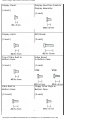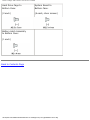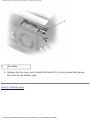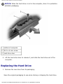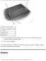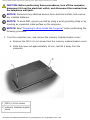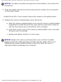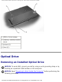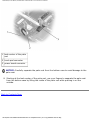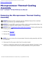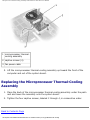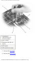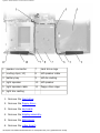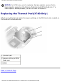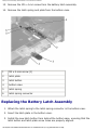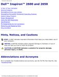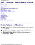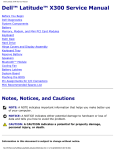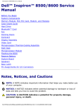
1
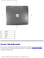
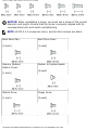
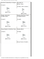
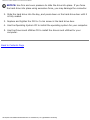
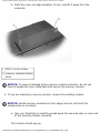
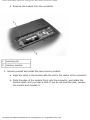
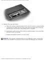
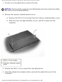
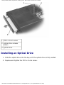
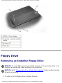
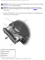
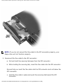
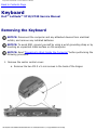
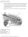
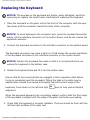
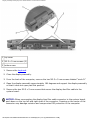
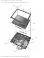
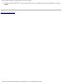
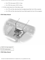
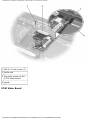
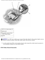
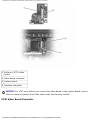
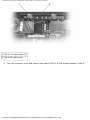
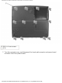
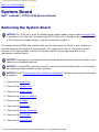
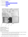
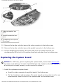
Dell Latitude V710/V740 Service Manual
Dell™ Latitude™ V710/V740 Service
Manual
Before You Begin
Preparing to Work Inside the Computer
Recommended Tools
Computer Orientation
Screw Identification
System Components
Back-Panel Fan (V740 Only)
Hard Drive
Memory Module, Modem, Optical Drive, and Floppy Drive
Memory Module
Modem
Optical Drive
Floppy Drive
Keyboard
Display Assembly and Display Latch
Display Assembly
Display Latch
EMI Shield, Video Board, and Palm Rest
EMI Shield
Video Board
Palm Rest
Microprocessor Thermal-Cooling Assembly
Microprocessor Module
Flashing the BIOS
Speakers
System Board
Base Plastics
Battery Latch Assembly
Pin Assignments for I/O Connectors
USB Connector
PS/2 Connector
Video Connector
file:///F|/Service%20Manuals/Dell/Latitude/v710-740/index.htm (1 of 2) [2/28/2004 8:22:01 AM]
Dell Latitude V710/V740 Service Manual
Parallel Connector
Notes, Notices, and Cautions
NOTE: A NOTE indicates important information that helps you make better use
of your computer.
NOTICE: A NOTICE indicates either potential damage to hardware or loss of
data and tells you how to avoid the problem.
CAUTION: A CAUTION indicates a potential for property damage,
personal injury, or death.
Trademarks used in this text: Dell, the DELL logo, and Latitude are trademarks of Dell Computer
Corporation; Intel is a registered trademarks of Intel Corporation; Microsoft and Windows are
registered trademarks of Microsoft Corporation.
Other trademarks and trade names may be used in this document to refer to either the entities
claiming the marks and names or their products. Dell Computer Corporation disclaims any proprietary
interest in trademarks and trade names other than its own.
April 2002 Rev. A01
file:///F|/Service%20Manuals/Dell/Latitude/v710-740/index.htm (2 of 2) [2/28/2004 8:22:01 AM]
Before You Begin: Dell Latitude V710/V740 Service Manual
Back to Contents Page
Before You Begin
Dell™ Latitude™ V710/V740 Service Manual
Preparing to Work Inside the Computer
Recommended Tools
Computer Orientation
Screw Identification
Preparing to Work Inside the Computer
CAUTION: Only a certified service technician should perform repairs on
your computer. Damage due to servicing that is not authorized by Dell
is not covered by your warranty. Read and follow applicable
instructions in "Safety and EMC Instructions: Portable Computers" in
the Latitude™ System Information Guide that came with the computer.
NOTICE: To avoid damaging the computer, perform the following steps before
you begin working inside the computer.
1. Ensure that the work surface is flat and clean to prevent scratching the
computer cover.
2. Save any work in progress and exit all open programs.
3. Turn off the computer and all attached devices.
NOTE: Ensure that the computer is off and not in a power management mode.
If you cannot shut down the computer using the computer operating system,
press and hold the power button for 4 seconds.
4. Disconnect the computer from the electrical outlet.
5. To avoid possible damage to the system board, wait 10 to 20 seconds and then
file:///F|/Service%20Manuals/Dell/Latitude/v710-740/begin.htm (1 of 8) [2/28/2004 8:22:07 AM]
Before You Begin: Dell Latitude V710/V740 Service Manual
disconnect any attached devices.
6. Disconnect all other external cables from the computer.
7. Remove any installed PC Cards from the PC Card slot.
8. Close the display and turn the computer upside down on a flat work surface.
NOTICE: To avoid damaging the system board, you must remove the main
battery before you service the computer.
CAUTION: When you remove the battery, ensure that the computer is
upside down on a flat work surface so that the battery does not fall out
of the computer.
9. Remove the battery:
a. Unlock the battery.
b. Slide and hold the battery latch release all the way up until the left edge of
the battery pops up.
c. Remove the battery.
file:///F|/Service%20Manuals/Dell/Latitude/v710-740/begin.htm (2 of 8) [2/28/2004 8:22:07 AM]
Before You Begin: Dell Latitude V710/V740 Service Manual
1 battery lock
2 battery latch release
3 battery
10. To dissipate any static electricity while you work, use a wrist grounding strap or
periodically touch an unpainted metal surface.
11. Handle components and cards with care. Do not touch the components or
contacts on a card. Hold a card by its edges or by its metal mounting bracket.
Hold a component such as a microprocessor by its edges, not by its pins.
Recommended Tools
The procedures in this manual require the following tools:
●
#1 magnetized Phillips screwdriver
●
¼-inch flat-blade screwdriver
●
Nut driver
●
Small plastic scribe
●
Microprocessor extractor
●
Flash BIOS update program floppy disk or CD
Computer Orientation
file:///F|/Service%20Manuals/Dell/Latitude/v710-740/begin.htm (3 of 8) [2/28/2004 8:22:07 AM]
Before You Begin: Dell Latitude V710/V740 Service Manual
1
back
2
right
3
front
4
left
Screw Identification
When you are removing and replacing components, photocopy "Screw Identification"
as a tool to lay out and keep track of the screws. The placemat provides the number
of screws and their sizes.
file:///F|/Service%20Manuals/Dell/Latitude/v710-740/begin.htm (4 of 8) [2/28/2004 8:22:07 AM]
Before You Begin: Dell Latitude V710/V740 Service Manual
NOTICE: When reinstalling a screw, you must use a screw of the correct
diameter and length. Ensure that the screw is properly aligned with its
corresponding hole, and avoid overtightening.
NOTE: All M2.5 x 4 screws are silver, and all other screws are black.
Back-Panel Fan:
Hard Drive Door:
(2 each)
(1 each)
Memory Module/
Modem Cover:
Modem to System Board:
(1 each)
(2 each)
Optical Drive:
Floppy Drive:
(1 each)
(2 each)
file:///F|/Service%20Manuals/Dell/Latitude/v710-740/begin.htm (5 of 8) [2/28/2004 8:22:07 AM]
Before You Begin: Dell Latitude V710/V740 Service Manual
Keyboard Assembly to Hinges: Keyboard to
Bottom Case:
(2 each)
(4 each; silver screws)
Display Assembly
to Back Panel:
Display-Feed Flex Cable
to System Board:
(2 each)
(2 each)
Hinge Bracket to Bottom Case: Display Bezel:
(4 each)
(5 each)
Screw Covers (5 each)
file:///F|/Service%20Manuals/Dell/Latitude/v710-740/begin.htm (6 of 8) [2/28/2004 8:22:07 AM]
Before You Begin: Dell Latitude V710/V740 Service Manual
Display Panel:
(4 each)
Display-Feed Flex Cable to
Display Assembly:
(1 each)
Display Latch:
EMI Shield:
(2 each)
(3 each)
Top of Palm Rest to
Bottom Case:
Video Board
to Bottom Case:
(2 each)
(1 each)
Palm Rest to
Bottom Case:
Floppy Drive Cage to
Bottom Case:
(12 each)
(2 each)
file:///F|/Service%20Manuals/Dell/Latitude/v710-740/begin.htm (7 of 8) [2/28/2004 8:22:07 AM]
Before You Begin: Dell Latitude V710/V740 Service Manual
Hard Drive Cage to
Bottom Case:
System Board to
Bottom Case:
(2 each)
(6 each; silver screws)
Battery Latch Assembly
to Bottom Case:
(1 each)
Back to Contents Page
file:///F|/Service%20Manuals/Dell/Latitude/v710-740/begin.htm (8 of 8) [2/28/2004 8:22:07 AM]
System Components: Dell Latitude V710/V740 Service Manual
Back to Contents Page
System Components
Dell™ Latitude™ V710/V740 Service Manual
NOTICE: Only a certified service technician should perform repairs on your
computer. Damage due to servicing that is not authorized by Dell is not covered
by your warranty.
NOTICE: Unless otherwise noted, each procedure in this document assumes
that a part can be replaced by performing the removal procedure in reverse
order.
file:///F|/Service%20Manuals/Dell/Latitude/v710-740/system.htm (1 of 3) [2/28/2004 8:22:08 AM]
System Components: Dell Latitude V710/V740 Service Manual
1
display assembly
13 hard drive
2
display-feed flex
cable
14 hard drive cage
3
center control
cover
15 floppy drive cage
4
keyboard
16 floppy drive
5
video board
17 speaker
6
microprocessor
18 modem
7
system board
19 microprocessor thermalcooling assembly
8
battery connector
cover
20 headphone/microphone
bridge
9
optical drive
21 palm rest
10 back-panel fan
(V740 only)
22 memory module/modem
cover
11 bottom case
23 EMI shield
12 battery
Back to Contents Page
file:///F|/Service%20Manuals/Dell/Latitude/v710-740/system.htm (2 of 3) [2/28/2004 8:22:08 AM]
System Components: Dell Latitude V710/V740 Service Manual
file:///F|/Service%20Manuals/Dell/Latitude/v710-740/system.htm (3 of 3) [2/28/2004 8:22:08 AM]
Back-Panel Fan (V740 Only): Dell Latitude V710/V740 Service Manual
Back to Contents Page
Back-Panel Fan (V740 Only)
Dell™ Latitude™ V710/V740 Service Manual
Removing the Back-Panel Fan
NOTICE: To prevent data loss, turn off the computer before removing the backpanel fan. Do not remove the fan while the computer is on or in a power
management mode.
NOTICE: Read "Preparing to Work Inside the Computer" before performing the
following procedure.
1. Ensure that the work surface is flat and clean to prevent scratching the
computer cover.
2. Save and close any open files, exit any open programs, and shut down the
computer.
NOTICE: Disconnect the computer and any attached devices from electrical
outlets, and remove any installed batteries.
NOTICE: To avoid ESD, ground yourself by using a wrist grounding strap or by
touching an unpainted metal surface on the computer.
3. Turn the computer over. Use a #1 Phillips screwdriver to remove the two M2.5 x
5-mm screws from the fan cover, and place the screws in a safe location.
file:///F|/Service%20Manuals/Dell/Latitude/v710-740/fan.htm (1 of 4) [2/28/2004 8:22:09 AM]
Back-Panel Fan (V740 Only): Dell Latitude V710/V740 Service Manual
1 M2.5 x 5-mm screws (2)
2 fan cover
3 scalloped left edge of
fan cover
4. Use a small flat-blade screwdriver or plastic scribe to lift the scalloped left edge
of the fan cover, and pry the cover loose from the bottom case.
5. Lift the fan cover up and away from the bottom case.
6. Disconnect the fan cable connector from the system board.
7. Lift the fan out of the bottom case.
file:///F|/Service%20Manuals/Dell/Latitude/v710-740/fan.htm (2 of 4) [2/28/2004 8:22:09 AM]
Back-Panel Fan (V740 Only): Dell Latitude V710/V740 Service Manual
1
fan
2
fan cable connector
Replacing the Back-Panel Fan
1. Slide the fan into the bottom case.
2. Tuck the fan cable under the bottom case, and connect the cable to the system
board.
file:///F|/Service%20Manuals/Dell/Latitude/v710-740/fan.htm (3 of 4) [2/28/2004 8:22:09 AM]
Back-Panel Fan (V740 Only): Dell Latitude V710/V740 Service Manual
1
fan cable
3. Replace the fan cover, and reinstall the two M2.5 x 5-mm screws that secure
the cover to the bottom case.
Back to Contents Page
file:///F|/Service%20Manuals/Dell/Latitude/v710-740/fan.htm (4 of 4) [2/28/2004 8:22:09 AM]
Hard Drive: Dell Latitude V710/V740 Service Manual
Back to Contents Page
Hard Drive
Dell™ Latitude™ V710/V740 Service Manual
Removing the Hard Drive
NOTICE: To prevent data loss, turn off the computer before removing the hard
drive. Do not remove the hard drive while the computer is on or in a power
management mode.
NOTICE: Hard drives are extremely fragile; even a slight bump can damage the
drive.
CAUTION: If you remove the hard drive from the computer when the
drive is hot, do not touch the metal housing of the hard drive.
NOTICE: Read "Preparing to Work Inside the Computer" before performing the
following procedure.
1. Ensure that the work surface is flat and clean to prevent scratching the
computer cover.
2. Save and close any open files, exit any open programs, and shut down the
computer.
NOTICE: Disconnect the computer and any attached devices from electrical
outlets, and remove any installed batteries.
NOTICE: To avoid ESD, ground yourself by using a wrist grounding strap or by
touching an unpainted metal surface on the computer.
3. Turn the computer over. Use a #1 Phillips screwdriver to remove the M2.5 x 5mm screw from the hard drive door, and place the screw in a safe location.
file:///F|/Service%20Manuals/Dell/Latitude/v710-740/hdd.htm (1 of 3) [2/28/2004 8:22:09 AM]
Hard Drive: Dell Latitude V710/V740 Service Manual
NOTICE: When the hard drive is not in the computer, store it in protective
antistatic packaging.
1
bottom of computer
2
M2.5 x 5-mm screw
3
hard drive door
4. Lift the hard drive door to release it, and slide the hard drive out of the
computer.
Replacing the Hard Drive
1. Remove the new drive from its packaging.
Save the original packaging to use when storing or shipping the hard drive.
file:///F|/Service%20Manuals/Dell/Latitude/v710-740/hdd.htm (2 of 3) [2/28/2004 8:22:09 AM]
Hard Drive: Dell Latitude V710/V740 Service Manual
NOTICE: Use firm and even pressure to slide the drive into place. If you force
the hard drive into place using excessive force, you may damage the connector.
2. Slide the hard drive into the bay, and press down on the hard drive door until it
is fully seated.
3. Replace and tighten the M2.5 x 5-mm screw in the hard drive door.
4. Use the Operating System CD to install the operating system for your computer.
5. Use the Drivers and Utilities CD to install the drivers and utilities for your
computer.
Back to Contents Page
file:///F|/Service%20Manuals/Dell/Latitude/v710-740/hdd.htm (3 of 3) [2/28/2004 8:22:09 AM]
Memory Module, Modem, Optical Drive, and Floppy Drive: Dell Latitude V710/V740 Service Manual
Back to Contents Page
Memory Module, Modem, Optical
Drive, and Floppy Drive
Dell™ Latitude™ V710/V740 Service Manual
Memory Module
Modem
Optical Drive
Floppy Drive
Memory Module
Removing the Memory Module/Modem Cover
NOTE: This procedure covers removing and replacing the memory module
located under the memory module/modem cover on the bottom of the
computer. A second memory module resides on the upper surface of the system
board under the EMI shield. To replace the memory module under the EMI
shield, perform the procedure for removing the EMI shield. Then replace the
memory module.
NOTICE: Disconnect the computer and any attached devices from electrical
outlets, and remove any installed batteries.
NOTICE: To avoid ESD, ground yourself by using a wrist grounding strap or by
touching an unpainted metal surface on the computer.
NOTICE: Read "Preparing to Work Inside the Computer" before performing the
following procedure.
1. Turn the computer over, and remove the memory module/modem cover:
a. Remove the M2.5 x 5-mm screw from the memory module/modem cover.
file:///F|/Service%20Manuals/Dell/Latitude/v710-740/upgrades.htm (1 of 18) [2/28/2004 8:22:11 AM]
Memory Module, Modem, Optical Drive, and Floppy Drive: Dell Latitude V710/V740 Service Manual
b. Slide the cover out approximately 10 mm, and lift it away from the
computer.
1 M2.5 x 5-mm screw
2 memory module/modem
cover
NOTICE: To prevent damage to the memory module connector, do not use
tools to spread the inner metal tabs that secure the memory module.
2. If you are replacing a memory module, remove the existing module.
NOTICE: Handle memory modules by their edges, and do not touch the
components on a module.
a. Use your fingertips to carefully spread apart the securing clips on each end
of the memory module connector.
The module should pop up.
file:///F|/Service%20Manuals/Dell/Latitude/v710-740/upgrades.htm (2 of 18) [2/28/2004 8:22:11 AM]
Memory Module, Modem, Optical Drive, and Floppy Drive: Dell Latitude V710/V740 Service Manual
b. Remove the module from the connector.
1
securing clip
2
memory module
3. Ground yourself and install the new memory module:
a. Align the notch in the module with the slot in the center of the connector.
b. Slide the edge of the module firmly into the connector, and rotate the
module down until you hear a click. If you do not hear the click, remove
the module and reinstall it.
file:///F|/Service%20Manuals/Dell/Latitude/v710-740/upgrades.htm (3 of 18) [2/28/2004 8:22:11 AM]
Memory Module, Modem, Optical Drive, and Floppy Drive: Dell Latitude V710/V740 Service Manual
4. Replace the cover and screw:
a. Place the memory module/modem cover over the memory module/modem
compartment so that the end of the cover with the screw hole is lined up
with the lines and arrows on the bottom of the computer.
b. Press down on the center of the memory module/modem cover, and slide
the cover until it is secured.
c. Replace and tighten the M2.5 x 5-mm screw.
NOTICE: If the memory module/modem cover is difficult to close, remove the
module and reinstall it. Forcing the cover to close may damage your computer.
file:///F|/Service%20Manuals/Dell/Latitude/v710-740/upgrades.htm (4 of 18) [2/28/2004 8:22:11 AM]
Memory Module, Modem, Optical Drive, and Floppy Drive: Dell Latitude V710/V740 Service Manual
1 M2.5 x 5-mm screw
2 memory module/modem
cover
3 arrows (2)
4 lines (2)
5. Insert the battery into the battery bay, or connect the AC adapter to your
computer and an electrical outlet.
6. Turn on the computer.
As the computer boots, it detects the additional memory and automatically updates
the system configuration information.
Modem
file:///F|/Service%20Manuals/Dell/Latitude/v710-740/upgrades.htm (5 of 18) [2/28/2004 8:22:11 AM]
Memory Module, Modem, Optical Drive, and Floppy Drive: Dell Latitude V710/V740 Service Manual
CAUTION: Before performing these procedures, turn off the computer,
disconnect it from the electrical outlet, and disconnect the modem from
the telephone wall jack.
NOTICE: Disconnect any attached devices from electrical outlets, and remove
any installed batteries.
NOTICE: To avoid ESD, ground yourself by using a wrist grounding strap or by
touching an unpainted metal surface on the computer.
NOTICE: Read "Preparing to Work Inside the Computer" before performing the
following procedure.
1. Turn the computer over, and remove the memory module/modem cover:
a. Remove the M2.5 x 5-mm screw from the memory module/modem cover.
b. Slide the cover out approximately 10 mm, and lift it away from the
computer.
1 M2.5 x 5-mm screw
2 memory module/modem
cover
file:///F|/Service%20Manuals/Dell/Latitude/v710-740/upgrades.htm (6 of 18) [2/28/2004 8:22:11 AM]
Memory Module, Modem, Optical Drive, and Floppy Drive: Dell Latitude V710/V740 Service Manual
2. If a modem is not already installed, go to step 3. If you are replacing a modem,
remove the existing modem:
a. Remove the two M2 x 3-mm screws that secure the modem to the system
board, and set them aside.
b. Pull the modem straight up by the pull tab to lift the modem out of its
connector, and disconnect the modem cable.
1 M2 x 3-mm screws (2)
2 pull tab
3 modem cable connector
4 modem cable
3. Connect the modem cable to the new modem.
file:///F|/Service%20Manuals/Dell/Latitude/v710-740/upgrades.htm (7 of 18) [2/28/2004 8:22:11 AM]
Memory Module, Modem, Optical Drive, and Floppy Drive: Dell Latitude V710/V740 Service Manual
NOTICE: The cable connectors are keyed for correct insertion; do not force the
connections.
4. Align the modem with the screw holes and press the modem into its connector
on the system board.
Install the two M2 x 3-mm screws to secure the modem to the system board.
5. Replace the memory module/modem cover and screw:
a. Place the memory module/modem cover over the memory module/modem
compartment so that the end of the cover with the screw hole is lined up
with the lines and arrows on the bottom of the computer.
b. Press down on the center of the memory module/modem cover, and slide
the cover until it is secured.
c. Replace and tighten the M2.5 x 5-mm screw.
NOTICE: Replace the memory module/modem cover so that it is seated
properly around the edges and does not bulge near the center of the cover.
Tightening the memory-module/modem cover screw when the cover is
improperly seated can damage your computer.
file:///F|/Service%20Manuals/Dell/Latitude/v710-740/upgrades.htm (8 of 18) [2/28/2004 8:22:11 AM]
Memory Module, Modem, Optical Drive, and Floppy Drive: Dell Latitude V710/V740 Service Manual
1 M2.5 x 5-mm screw
2 memory module/modem
cover
3 arrows (2)
4 lines (2)
Optical Drive
Removing an Installed Optical Drive
NOTICE: To avoid ESD, ground yourself by using a wrist grounding strap or by
touching an unpainted metal surface on the computer.
NOTICE: Read "Preparing to Work Inside the Computer" before performing the
following procedure.
file:///F|/Service%20Manuals/Dell/Latitude/v710-740/upgrades.htm (9 of 18) [2/28/2004 8:22:11 AM]
Memory Module, Modem, Optical Drive, and Floppy Drive: Dell Latitude V710/V740 Service Manual
1. If a disc is in the optical drive, remove the disc.
NOTICE: Disconnect the computer and attached devices from electrical outlets,
and remove any installed batteries.
2. Remove the memory module/modem cover:
a. Remove the M2.5 x 5-mm screw from the memory module/modem cover.
b. Slide the cover out approximately 10 mm, and lift it away from the
computer.
1 M2.5 x 5-mm screw
2 memory module/modem
cover
3. Remove the M2.5 x 8-mm screw from the optical drive.
4. Press the optical-drive release button, and pull the optical drive out of the
computer.
file:///F|/Service%20Manuals/Dell/Latitude/v710-740/upgrades.htm (10 of 18) [2/28/2004 8:22:11 AM]
Memory Module, Modem, Optical Drive, and Floppy Drive: Dell Latitude V710/V740 Service Manual
1 M2.5 x 8-mm screw
2 optical-drive release
button
3 optical drive
Installing an Optical Drive
1. Slide the optical drive into the bay until the optical drive is fully seated.
2. Replace and tighten the M2.5 x 8-mm screw.
file:///F|/Service%20Manuals/Dell/Latitude/v710-740/upgrades.htm (11 of 18) [2/28/2004 8:22:11 AM]
Memory Module, Modem, Optical Drive, and Floppy Drive: Dell Latitude V710/V740 Service Manual
1
M2.5 x 8-mm screw
2
optical drive
NOTICE: Replace the memory module/modem cover so that it is seated
properly around the edges and does not bulge near the center of the cover.
Tightening the memory-module/modem cover screw when the cover is
improperly seated can damage your computer.
3. Replace the memory module/modem cover and screw:
a. Place the memory module/modem cover over the memory module
compartment so that the end of the cover with the screw hole is lined up
with the lines and arrows on the bottom of the computer.
b. Press down on the center of the memory module/modem cover, and slide
the memory module/modem cover until it is secured.
c. Replace and tighten the M2.5 x 5-mm screw.
file:///F|/Service%20Manuals/Dell/Latitude/v710-740/upgrades.htm (12 of 18) [2/28/2004 8:22:12 AM]
Memory Module, Modem, Optical Drive, and Floppy Drive: Dell Latitude V710/V740 Service Manual
1 M2.5 x 5-mm screw
2 memory module/modem
cover
3 arrows (2)
4 lines (2)
Floppy Drive
Removing an Installed Floppy Drive
NOTICE: To avoid ESD, ground yourself by using a wrist grounding strap or by
touching an unpainted metal surface on the computer.
NOTICE: Read "Preparing to Work Inside the Computer" before performing the
following procedure.
1. If a disk is in the floppy drive, remove the disk.
file:///F|/Service%20Manuals/Dell/Latitude/v710-740/upgrades.htm (13 of 18) [2/28/2004 8:22:12 AM]
Memory Module, Modem, Optical Drive, and Floppy Drive: Dell Latitude V710/V740 Service Manual
NOTICE: Disconnect the computer and attached devices from electrical outlets,
and remove any installed batteries.
NOTICE: Ensure that you disconnect the flex cable from the ZIF connector
before you remove the floppy drive from the computer. See step 3 for further
instructions.
2. Remove the two M2.5 x 5-mm screws from the floppy drive, and partially pull
the drive out of the computer.
1 M2.5 x 5-mm screws (2)
2 ZIF connector
3 floppy drive
4 flex cable
file:///F|/Service%20Manuals/Dell/Latitude/v710-740/upgrades.htm (14 of 18) [2/28/2004 8:22:12 AM]
Memory Module, Modem, Optical Drive, and Floppy Drive: Dell Latitude V710/V740 Service Manual
NOTICE: Release the securing tab before you disconnect the flex cable from the
ZIF connector. Failure to do so can damage the ZIF connector.
3. Disconnect the flex cable from the ZIF connector:
a. Pull the securing tab away from the ZIF connector.
b. Gently pull the flex cable out of the ZIF connector.
1
ZIF connector
2
securing tab
3
flex cable
Installing a Floppy Drive
1. Slide the floppy drive partially into the bay.
file:///F|/Service%20Manuals/Dell/Latitude/v710-740/upgrades.htm (15 of 18) [2/28/2004 8:22:12 AM]
Memory Module, Modem, Optical Drive, and Floppy Drive: Dell Latitude V710/V740 Service Manual
NOTE: If you do not connect the flex cable to the ZIF connector properly, your
floppy drive will not function properly.
2. Reconnect the flex cable to the ZIF connector:
a. Pull and hold the securing tab away from the ZIF connector.
b. While holding the securing tab, insert the flex cable into the ZIF connector.
Ensure that you insert the flex cable into the ZIF connector and not below the
ZIF connector.
c. Hold the flex cable in place and push the securing tab toward the ZIF
connector.
file:///F|/Service%20Manuals/Dell/Latitude/v710-740/upgrades.htm (16 of 18) [2/28/2004 8:22:12 AM]
Memory Module, Modem, Optical Drive, and Floppy Drive: Dell Latitude V710/V740 Service Manual
1
ZIF connector
2
securing tab
3
flex cable
3. Slide the floppy drive into the bay until the drive is fully seated.
4. Replace and tighten the two M2.5 x 5-mm screws.
5. Install the battery.
6. Turn on the computer and try using the floppy drive.
If the computer does not detect the floppy drive, you may have improperly
inserted the flex cable. If so, disconnect the flex cable and reconnect it to the ZIF
connector.
file:///F|/Service%20Manuals/Dell/Latitude/v710-740/upgrades.htm (17 of 18) [2/28/2004 8:22:12 AM]
Memory Module, Modem, Optical Drive, and Floppy Drive: Dell Latitude V710/V740 Service Manual
Back to Contents Page
file:///F|/Service%20Manuals/Dell/Latitude/v710-740/upgrades.htm (18 of 18) [2/28/2004 8:22:12 AM]
Keyboard: Dell Latitude V710/V740 Service Manual
Back to Contents Page
Keyboard
Dell™ Latitude™ V710/V740 Service Manual
Removing the Keyboard
NOTICE: Disconnect the computer and any attached devices from electrical
outlets, and remove any installed batteries.
NOTICE: To avoid ESD, ground yourself by using a wrist grounding strap or by
touching an unpainted metal surface on the computer.
NOTICE: Read "Preparing to Work Inside the Computer" before performing the
following procedure.
1. Remove the center control cover:
a. Remove the two M2.5 x 5-mm screws in the back of the hinges.
file:///F|/Service%20Manuals/Dell/Latitude/v710-740/keyboard.htm (1 of 6) [2/28/2004 8:22:13 AM]
Keyboard: Dell Latitude V710/V740 Service Manual
1 M2.5 x 5-mm screws (2)
b. Open the display assembly at an angle of approximately 180 degrees and
support the display assembly so that it does not open past this position.
c. Use a small flat-blade screwdriver or plastic scribe to lift the scalloped
right edge of the center control cover and pry the cover loose from the
hinges and bottom case.
d. Lift the center control cover up and away from the hinges and bottom
case.
1 scalloped edge of center
control cover
2 center control cover
3 display assembly
file:///F|/Service%20Manuals/Dell/Latitude/v710-740/keyboard.htm (2 of 6) [2/28/2004 8:22:13 AM]
Keyboard: Dell Latitude V710/V740 Service Manual
NOTE: The M2.5 x 4 screws are silver.
2. Remove the four M2.5 x 4-mm screws across the top of the keyboard.
1 M2.5 x 4-mm screws (4)
2 scalloped edge of blank
key
3 keyboard
4 palm rest
NOTICE: The keycaps on the keyboard are fragile, easily dislodged, and timeconsuming to replace. Be careful when removing and handling the keyboard.
3. Lift the keyboard straight up until it clears the top of the bottom case.
4. Rotate the keyboard forward toward the front of the computer.
5. Rest the key face of the keyboard on the palm rest.
file:///F|/Service%20Manuals/Dell/Latitude/v710-740/keyboard.htm (3 of 6) [2/28/2004 8:22:13 AM]
Keyboard: Dell Latitude V710/V740 Service Manual
NOTICE: Do not pull on the keyboard flex cable.
6. Pull up on the keyboard connector to disconnect it from the interface connector
on the system board.
1 keyboard securing tabs
(4)
2 keyboard flex cable
3 keyboard connector
4 interface connector on
system board
7. Remove the keyboard from the bottom case.
file:///F|/Service%20Manuals/Dell/Latitude/v710-740/keyboard.htm (4 of 6) [2/28/2004 8:22:13 AM]
Keyboard: Dell Latitude V710/V740 Service Manual
Replacing the Keyboard
NOTICE: The keycaps on the keyboard are fragile, easily dislodged, and timeconsuming to replace. Be careful when handling and replacing the keyboard.
1. Place the keyboard on the palm rest at the front of the computer with the keys
face down and the connector toward the back of the computer.
NOTICE: To avoid damage to the connector pins, press the keyboard connector
evenly into the interface connector on the system board, and do not reverse the
keyboard connector.
2. Connect the keyboard connector to the interface connector on the system board.
The keyboard connector may have a label on it that shows the correct orientation
of the keyboard connector to the interface connector on the system board.
NOTICE: Position the keyboard flex cable so that it is not pinched when you
replace the keyboard in the bottom case.
3. Rotate the keyboard back and fit it into the bottom case.
Ensure that all four securing tabs are engaged in their respective slots before
trying to completely seat the keyboard. Fitting the tabs to the slots may be
easiest when viewed from above and slightly behind the front edge of the
keyboard. Press down on the left and right
alignment.
keys to help control tab/slot
When the keyboard appears to be completely seated, confirm that the front edge
of the keyboard is aligned with the edge of the palm rest before proceeding.
4. Check that the keyboard is correctly installed. The keys should be flush with the
left and right surfaces of the palm rest.
file:///F|/Service%20Manuals/Dell/Latitude/v710-740/keyboard.htm (5 of 6) [2/28/2004 8:22:13 AM]
Keyboard: Dell Latitude V710/V740 Service Manual
NOTE: The M2.5 x 4 screws are silver.
5. Replace the four M2.5 x 4-mm screws at the top of the keyboard.
6. Replace the center control cover.
Ensure that the center control cover is snapped in properly so that it is flush with
the keyboard.
7. Replace the two M2.5 x 5-mm screws in the back of the hinges.
Back to Contents Page
file:///F|/Service%20Manuals/Dell/Latitude/v710-740/keyboard.htm (6 of 6) [2/28/2004 8:22:13 AM]
Display Assembly and Display Latch: Dell Latitude V710/V740 Service Manual
Back to Contents Page
Display Assembly and Display Latch
Dell™ Latitude™ V710/V740 Service Manual
Display Assembly
Display Latch
Display Assembly
NOTICE: You must remove the display assembly before you remove the palm rest.
NOTICE: Disconnect the computer and any attached devices from electrical outlets, and
remove any installed batteries.
NOTICE: To avoid ESD, ground yourself by using a wrist grounding strap or by touching
an unpainted metal surface on the computer.
NOTICE: Read "Preparing to Work Inside the Computer" before performing the following
procedure.
file:///F|/Service%20Manuals/Dell/Latitude/v710-740/display.htm (1 of 10) [2/28/2004 8:22:14 AM]
Display Assembly and Display Latch: Dell Latitude V710/V740 Service Manual
1 top cover
2 M2.5 x 5-mm screws (2)
3 bottom case
1. Remove the keyboard.
2. Close the display assembly.
3. From the back of the computer, remove the two M2.5 x 5-mm screws labeled "circle D."
4. Open the display assembly approximately 180 degrees and support the display assembly
so that it does not open past this position.
5. Remove the two M2.5 x 5-mm screws that secure the display-feed flex cable to the
system board.
NOTICE: When reconnecting the display-feed flex cable connector to the system board,
push down on the top left and right ends of the connector. Pressing on the center of the
connector may damage resistors and compromise EMI protection in the computer.
file:///F|/Service%20Manuals/Dell/Latitude/v710-740/display.htm (2 of 10) [2/28/2004 8:22:14 AM]
Display Assembly and Display Latch: Dell Latitude V710/V740 Service Manual
1 M2.5 x 5-mm screws (4)
2 hinge blocks (2)
3 M2.5 x 5-mm screws (2)
4 display-feed flex cable
5 pull tab
6. Pull up on the pull tab that is attached to the display-feed flex cable connector to remove
the connector from the system board.
7. Remove the two M2.5 x 5-mm screws from each hinge block.
file:///F|/Service%20Manuals/Dell/Latitude/v710-740/display.htm (3 of 10) [2/28/2004 8:22:14 AM]
Display Assembly and Display Latch: Dell Latitude V710/V740 Service Manual
8. Lift the display assembly up and out of the bottom case.
file:///F|/Service%20Manuals/Dell/Latitude/v710-740/display.htm (4 of 10) [2/28/2004 8:22:14 AM]
Display Assembly and Display Latch: Dell Latitude V710/V740 Service Manual
1 screw covers (5)
6
M2 x 3-mm screws (4)
2 M2.5 x 5-mm screws
(5)
7
M2.5 x 5-mm screw (1)
3 display bezel
8
display-feed flex cable
4 display panel
9
flex-cable retention
bracket
5 M2.5 x 5-mm screws
(2)
10 top cover
Removing the Display Bezel
NOTICE: Disconnect the computer and any attached devices from electrical outlets, and
remove any installed batteries.
NOTICE: To avoid ESD, ground yourself by using a wrist grounding strap or by touching
an unpainted metal surface on the computer.
NOTICE: Read "Preparing to Work Inside the Computer" before performing the following
procedure.
1. Remove the keyboard.
2. Remove the display assembly.
3. Use a plastic scribe to pry the five screw covers out of the screw holes located on the front
of the bezel.
4. Remove the five M2.5 x 5-mm screws located on the front of the bezel.
NOTICE: Carefully separate the bezel from the top cover to avoid damage to the bezel.
5. Starting at the bottom of the display panel (by the Dell™ logo), use your fingers to
separate the bezel from the top cover by lifting the inside of the bezel while pushing in on
the outside.
Removing the Display Panel
NOTICE: Disconnect the computer and any attached devices from electrical outlets, and
remove any installed batteries.
file:///F|/Service%20Manuals/Dell/Latitude/v710-740/display.htm (5 of 10) [2/28/2004 8:22:14 AM]
Display Assembly and Display Latch: Dell Latitude V710/V740 Service Manual
NOTICE: To avoid ESD, ground yourself by using a wrist grounding strap or by touching
an unpainted metal surface on the computer.
NOTICE: Read "Preparing to Work Inside the Computer" before performing the following
procedure.
1. Remove the keyboard.
2. Remove the display assembly.
3. Remove the display bezel.
4. Remove the two M2 x 3-mm screws on the left side of the display panel.
5. Remove the two M2 x 3-mm screws on the right side of the display panel.
6. Remove the M2.5 x 5-mm screw that secures the display-feed flex cable to the display
assembly.
7. Unsnap the flex-cable retention bracket from the top cover, and lift the bracket out of the
display assembly.
1 flex-cable retention
bracket
8. Lift the display panel from the top, and rotate the display panel out of the top cover.
file:///F|/Service%20Manuals/Dell/Latitude/v710-740/display.htm (6 of 10) [2/28/2004 8:22:14 AM]
Display Assembly and Display Latch: Dell Latitude V710/V740 Service Manual
9. Disconnect the bottom flex cable connector from the inverter connector on the system
board by pulling on the attached pull tab away from the inverter connector.
1 top flex cable connector
2 display panel connector
3 pull tab
4 pull tab
5 inverter connector on
system board
file:///F|/Service%20Manuals/Dell/Latitude/v710-740/display.htm (7 of 10) [2/28/2004 8:22:14 AM]
Display Assembly and Display Latch: Dell Latitude V710/V740 Service Manual
6 bottom flex cable
connector
10. Remove the tape that secures the display panel connector and the tape that secures the
middle of the display-feed flex cable to the display panel.
11. Pull the top flex cable connector down and away to remove it from the display panel
connector.
Replacing the Display Panel
1. Reconnect the top flex cable connector to the display panel connector.
2. Reconnect the bottom flex cable connector to the inverter connector on the system board.
3. Replace the tape that secures the display panel connector and the tape that secures the
middle of the display-feed flex cable to the display panel.
4. Place the bottom edge of the display panel in the bottom of the top cover and elevate the
top of the panel with your hand.
5. Lay the display panel in the top cover.
6. Reinstall the four M2 x 3-mm screws that secure the display panel to the top cover.
7. Reinstall the M2.5 x 5-mm screw that secures the display-feed flex cable to the display
assembly.
Display Latch
NOTICE: Disconnect the computer and any attached devices from electrical outlets, and
remove any installed batteries.
NOTICE: To avoid ESD, ground yourself by using a wrist grounding strap or by touching
an unpainted metal surface on the computer.
Removing the Display Latch
1. Remove the keyboard.
2. Remove the display assembly.
file:///F|/Service%20Manuals/Dell/Latitude/v710-740/display.htm (8 of 10) [2/28/2004 8:22:14 AM]
Display Assembly and Display Latch: Dell Latitude V710/V740 Service Manual
3. Remove the display bezel.
4. Remove the two M2.5 x 5-mm screws that secure the display latch and bracket to the top
cover.
5. Lift the display latch, bracket, and spring up and out of the top cover.
1 spring
2 spring hook (display
latch)
3 M2.5 x 5-mm screws (2)
4 display latch
5 bracket
6 spring hook (top cover)
Replacing the Display Latch
1. Attach one end of the spring to the spring hook on the left edge of the display latch, and
attach the other end of the spring to the spring hook in the top cover.
2. Place the display latch on top of its screw holes, and then place the bracket on top of the
display latch, aligning the bracket and display latch screw holes.
file:///F|/Service%20Manuals/Dell/Latitude/v710-740/display.htm (9 of 10) [2/28/2004 8:22:14 AM]
Display Assembly and Display Latch: Dell Latitude V710/V740 Service Manual
3. Replace the two M2.5 x 5-mm screws that secure the display latch and bracket to the top
cover.
Back to Contents Page
file:///F|/Service%20Manuals/Dell/Latitude/v710-740/display.htm (10 of 10) [2/28/2004 8:22:14 AM]
EMI Shield, Video Board, and Palm Rest: Dell Latitude V710/V740 Service Manual
Back to Contents Page
EMI Shield, Video Board, and Palm Rest
Dell™ Latitude™ V710/V740 Service Manual
EMI Shield
Video Board
Palm Rest
EMI Shield
NOTICE: Disconnect the computer and any attached devices from electrical outlets, and
remove any installed batteries.
NOTICE: To avoid ESD, ground yourself by using a wrist grounding strap or by touching
an unpainted metal surface on the computer.
NOTICE: Read "Preparing to Work Inside the Computer" before performing the following
procedure.
1. Remove the keyboard.
2. Remove the two M2.5 x 5-mm screws that secure the display-feed flex cable to the
system board.
NOTICE: When reconnecting the display-feed flex cable connector to the system board,
push down on the top left and right ends of the connector. Pressing on the center of the
connector may damage resistors and compromise EMI protection in the computer.
3. Pull up on the pull tab that is attached to the display-feed flex cable connector to remove
the connector from the system board.
4. Remove the three M2.5 x 12-mm screws that secure the EMI shield to the bottom case,
and pull the EMI shield out of the bottom case.
file:///F|/Service%20Manuals/Dell/Latitude/v710-740/palmrest.htm (1 of 12) [2/28/2004 8:22:16 AM]
EMI Shield, Video Board, and Palm Rest: Dell Latitude V710/V740 Service Manual
1 EMI shield
2 M2.5 x 12-mm screws
(3)
Video Board
Removing the Video Board
NOTICE: Disconnect the computer and any attached devices from electrical outlets, and
remove any installed batteries.
NOTICE: To avoid ESD, ground yourself by using a wrist grounding strap or by touching
an unpainted metal surface on the computer.
NOTICE: Read "Preparing to Work Inside the Computer" before performing the following
procedure.
1. Remove the keyboard.
2. Remove the EMI Shield.
3. Remove the screw that secures the video board to the system board:
file:///F|/Service%20Manuals/Dell/Latitude/v710-740/palmrest.htm (2 of 12) [2/28/2004 8:22:16 AM]
EMI Shield, Video Board, and Palm Rest: Dell Latitude V710/V740 Service Manual
●
For V710, the screw is M2.5 x 5 mm.
●
For V740, the screw is M2.5 x 8mm.
4. Pull the video board out of the bottom case:
●
For V710, pull the video board by the edges toward the front of the computer.
●
For V740, pull the video board by the pull tab toward the front of the computer.
V710 Video Board
1 M2.5 x 5-mm screw (1)
2 V710 video board
V740 Video Board
file:///F|/Service%20Manuals/Dell/Latitude/v710-740/palmrest.htm (3 of 12) [2/28/2004 8:22:16 AM]
EMI Shield, Video Board, and Palm Rest: Dell Latitude V710/V740 Service Manual
1 V740 video board
2 M2.5 x 8-mm screw (1)
3 pull tab
Replacing the Video Board
1. Align the top right corner of the video board with the guide on the system board, and
slide the top edge of the video board under the palm rest.
V710 Video Board
file:///F|/Service%20Manuals/Dell/Latitude/v710-740/palmrest.htm (4 of 12) [2/28/2004 8:22:16 AM]
EMI Shield, Video Board, and Palm Rest: Dell Latitude V710/V740 Service Manual
1 M2.5 x 5-mm screw (1)
2 palm rest
3 top right corner of the
V710 video board
4 guide
V740 Video Board
file:///F|/Service%20Manuals/Dell/Latitude/v710-740/palmrest.htm (5 of 12) [2/28/2004 8:22:16 AM]
EMI Shield, Video Board, and Palm Rest: Dell Latitude V710/V740 Service Manual
1 M2.5 x 8-mm screw (1)
2 palm rest
3 top right corner of the
V740 video board
4 guide
NOTICE: For V740 only, before you connect the video board to the system board, ensure
that you route the power- board flex cable under the memory module.
2. Lay the video board flat on the system board, and connect the video board connector to
the interface connector on the system board.
V710 Video Board Connector
file:///F|/Service%20Manuals/Dell/Latitude/v710-740/palmrest.htm (6 of 12) [2/28/2004 8:22:16 AM]
EMI Shield, Video Board, and Palm Rest: Dell Latitude V710/V740 Service Manual
1 bottom of V710 video
board
2 video board connector
3 system board
4 interface connector
NOTICE: For V740 only, before you connect the video board to the system board, ensure
that you route the power- board flex cable under the memory module.
V740 Video Board Connector
file:///F|/Service%20Manuals/Dell/Latitude/v710-740/palmrest.htm (7 of 12) [2/28/2004 8:22:16 AM]
EMI Shield, Video Board, and Palm Rest: Dell Latitude V710/V740 Service Manual
1 bottom of V740 video
board
2 video board connector
3 system board
4 interface connector
5 power-board flex cable
6 memory module
3. Reinstall the screw that secures the video board to the bottom case:
●
For V710, reinstall the M2.5 x 5-mm screw.
●
For V740, reinstall the M2.5 x 8-mm screw.
4. Replace the EMI Shield.
file:///F|/Service%20Manuals/Dell/Latitude/v710-740/palmrest.htm (8 of 12) [2/28/2004 8:22:16 AM]
EMI Shield, Video Board, and Palm Rest: Dell Latitude V710/V740 Service Manual
5. Replace the keyboard.
Palm Rest
NOTICE: Disconnect the computer and any attached devices from electrical outlets, and
remove any installed batteries.
NOTICE: To avoid ESD, ground yourself by using a wrist grounding strap or by touching
an unpainted metal surface on the computer.
NOTICE: Read "Preparing to Work Inside the Computer" before performing the following
procedure.
1. Remove the keyboard.
NOTICE: You must remove the display assembly before you remove the palm rest; the
display hinges pass through the back of the palm rest.
2. Remove the display assembly.
3. Remove the EMI Shield.
4. Remove the video board.
5. Remove the two M2.5 x 5-mm screws from the top of the palm rest.
file:///F|/Service%20Manuals/Dell/Latitude/v710-740/palmrest.htm (9 of 12) [2/28/2004 8:22:16 AM]
EMI Shield, Video Board, and Palm Rest: Dell Latitude V710/V740 Service Manual
1 M2.5 x 5-mm screws (2)
2 top of the palm rest
6. Turn the computer over and remove the twelve M2.5 x 8-mm screws labeled "circle P."
file:///F|/Service%20Manuals/Dell/Latitude/v710-740/palmrest.htm (10 of 12) [2/28/2004 8:22:16 AM]
EMI Shield, Video Board, and Palm Rest: Dell Latitude V710/V740 Service Manual
1 M2.5 x 8-mm screws
(12)
7. Turn the computer over, and disconnect the touch pad connector and power board
connector from the system board.
file:///F|/Service%20Manuals/Dell/Latitude/v710-740/palmrest.htm (11 of 12) [2/28/2004 8:22:16 AM]
EMI Shield, Video Board, and Palm Rest: Dell Latitude V710/V740 Service Manual
1 back center of the palm
rest
2 touch pad connector
3 power board connector
NOTICE: Carefully separate the palm rest from the bottom case to avoid damage to the
palm rest.
8. Starting at the back center of the palm rest, use your fingers to separate the palm rest
from the bottom case by lifting the inside of the palm rest while pushing in on the
outside.
Back to Contents Page
file:///F|/Service%20Manuals/Dell/Latitude/v710-740/palmrest.htm (12 of 12) [2/28/2004 8:22:16 AM]
Microprocessor Thermal-Cooling Assembly: Dell Latitude V710/V740 Service Manual
Back to Contents Page
Microprocessor Thermal-Cooling
Assembly
Dell™ Latitude™ V710/V740 Service Manual
Removing the Microprocessor Thermal-Cooling
Assembly
NOTICE: Disconnect the computer and any attached devices from electrical
outlets, and remove any installed batteries.
NOTICE: To avoid ESD, ground yourself by using a wrist grounding strap or by
touching an unpainted metal surface on the computer.
NOTICE: Read "Preparing to Work Inside the Computer" before performing the
following procedure.
1. Remove the keyboard.
2. Remove the EMI Shield.
NOTE: You can remove the microprocessor thermal-cooling assembly with the
fan attached.
3. Disconnect the fan power cable from the system board.
4. Loosen in consecutive order the four captive screws, labeled 1 through 4, that
secure the microprocessor thermal-cooling assembly to the system board.
file:///F|/Service%20Manuals/Dell/Latitude/v710-740/thermal.htm (1 of 3) [2/28/2004 8:22:16 AM]
Microprocessor Thermal-Cooling Assembly: Dell Latitude V710/V740 Service Manual
1 microprocessor thermalcooling assembly
2 captive screws (4)
3 fan power cable
5. Lift the microprocessor thermal-cooling assembly up toward the front of the
computer and out of the system board.
Replacing the Microprocessor Thermal-Cooling
Assembly
1. Place the back of the microprocessor thermal-cooling assembly under the palm
rest and lower the assembly onto the system board.
2. Tighten the four captive screws, labeled 1 through 4, in consecutive order.
Back to Contents Page
file:///F|/Service%20Manuals/Dell/Latitude/v710-740/thermal.htm (2 of 3) [2/28/2004 8:22:16 AM]
Microprocessor Thermal-Cooling Assembly: Dell Latitude V710/V740 Service Manual
file:///F|/Service%20Manuals/Dell/Latitude/v710-740/thermal.htm (3 of 3) [2/28/2004 8:22:16 AM]
Microprocessor Module: Dell Latitude V710/V740 Service Manual
Back to Contents Page
Microprocessor Module
Dell™ Latitude™ V710/V740 Service Manual
Removing the Microprocessor Module
NOTICE: Disconnect the computer and any attached devices from electrical
outlets, and remove any installed batteries.
NOTICE: To avoid ESD, ground yourself by using a wrist grounding strap or by
touching an unpainted metal surface on the computer.
NOTICE: Read "Preparing to Work Inside the Computer" before performing the
following procedure.
NOTICE: Do not touch the processor die. Press and hold the microprocessor
down on the substrate on which the die is mounted while turning the cam screw
to prevent intermittent contact between the cam screw and microprocessor.
NOTICE: To avoid damage to the microprocessor, hold the screwdriver so that
it is perpendicular to the microprocessor when turning the cam screw.
file:///F|/Service%20Manuals/Dell/Latitude/v710-740/cpu.htm (1 of 4) [2/28/2004 8:22:17 AM]
Microprocessor Module: Dell Latitude V710/V740 Service Manual
1 screwdriver
(perpendicular to
microprocessor)
2 pin-1 corner
3 processor die (do not
touch)
4 ZIF socket
5 ZIF-socket cam screw
1. Remove the keyboard.
2. Remove the EMI Shield.
file:///F|/Service%20Manuals/Dell/Latitude/v710-740/cpu.htm (2 of 4) [2/28/2004 8:22:17 AM]
Microprocessor Module: Dell Latitude V710/V740 Service Manual
NOTICE: To ensure maximum cooling for the microprocessor, do not touch the
heat transfer areas on the microprocessor thermal-cooling assembly. The oils in
your skin reduce the heat transfer capability of the thermal pads.
3. Remove the microprocessor thermal-cooling assembly.
NOTICE: When removing the microprocessor module, pull the module straight
up. Be careful not to bend the pins on the microprocessor module.
4. To loosen the ZIF socket, use a small, flat-blade screwdriver and rotate the ZIFsocket cam screw counterclockwise until it comes to the cam stop.
The ZIF-socket cam screw secures the microprocessor to the system board. Take
note of the arrow on the ZIF-socket cam screw.
5. Use a microprocessor extraction tool to remove the microprocessor module.
Replacing the Microprocessor Module
NOTICE: Ensure that the cam lock is in the fully open position before seating
the microprocessor module. Seating the microprocessor module properly in the
ZIF socket does not require force.
NOTICE: A microprocessor module that is not properly seated can result in an
intermittent connection, or permanent damage to the microprocessor and ZIF
socket.
1. Align the pin-1 corner of the microprocessor module with the pin-1 corner of the
ZIF socket, and insert the microprocessor module.
NOTE: The pin-1 corner of the microprocessor module has a triangle that aligns
with the triangle on the pin-1 corner of the ZIF socket.
NOTICE: You must position the microprocessor module correctly in the ZIF
socket to avoid permanent damage to the module and the socket.
file:///F|/Service%20Manuals/Dell/Latitude/v710-740/cpu.htm (3 of 4) [2/28/2004 8:22:17 AM]
Microprocessor Module: Dell Latitude V710/V740 Service Manual
When the microprocessor module is correctly seated, all four corners are aligned
at the same height. If one or more corners of the module are higher than the
others, the module is not seated correctly.
NOTICE: Hold the microprocessor down while turning the cam screw to prevent
intermittent contact between the cam screw and microprocessor.
2. Tighten the ZIF socket by turning the cam screw clockwise to secure the
microprocessor module to the system board.
3. Update the BIOS using a flash BIOS update program floppy disk or CD. For
instructions on how to flash the BIOS, see "Flashing the BIOS."
Back to Contents Page
file:///F|/Service%20Manuals/Dell/Latitude/v710-740/cpu.htm (4 of 4) [2/28/2004 8:22:17 AM]
Flashing the BIOS: Dell Latitude V710/V740 Service Manual
Back to Contents Page
Flashing the BIOS
Dell™ Latitude™ V710/V740 Service Manual
1. Ensure that the AC adapter is plugged in and that the main battery is installed
properly.
2. Turn on the computer.
Follow the instructions that appear on the screen. The computer continues to boot
and updates the new BIOS. When the flash update is complete, the computer will
automatically reboot.
3. Press
during POST to enter the system setup program.
4. Press
to reset the computer defaults.
5. Press
to save configuration changes and exit the system setup program.
6. Remove the flash BIOS update program floppy disk or CD from the drive and
restart the computer.
Back to Contents Page
file:///F|/Service%20Manuals/Dell/Latitude/v710-740/bios.htm [2/28/2004 8:22:17 AM]
Speakers: Dell Latitude V710/V740 Service Manual
Back to Contents Page
Speakers
Dell™ Latitude™ V710/V740 Service Manual
Removing the Speakers
NOTICE: Disconnect the computer and any attached devices from electrical
outlets, and remove any installed batteries.
NOTICE: To avoid ESD, ground yourself by using a wrist grounding strap or by
touching an unpainted metal surface on the computer.
NOTICE: Read "Preparing to Work Inside the Computer" before performing the
following procedure.
The speakers are located on the left and right corners of the front of the bottom case.
Take note of the speaker cable routing so that you can replace the cables properly
under or between their routing clips.
file:///F|/Service%20Manuals/Dell/Latitude/v710-740/speakers.htm (1 of 4) [2/28/2004 8:22:18 AM]
Speakers: Dell Latitude V710/V740 Service Manual
1
speaker connector
7
hard drive cage
2
routing clips (10)
8
left speaker cable
3
battery bay
9
left die casting
4
right speaker
10
left speaker
5
right speaker cable
11
floppy drive cage
6
right die casting
1. Remove the hard drive.
2. Remove the floppy drive.
3. Remove the keyboard.
4. Remove the display assembly.
5. Remove the EMI Shield.
6. Remove the video board.
file:///F|/Service%20Manuals/Dell/Latitude/v710-740/speakers.htm (2 of 4) [2/28/2004 8:22:18 AM]
Speakers: Dell Latitude V710/V740 Service Manual
7. Remove the palm rest.
8. Disconnect the speaker connector from the system board.
NOTICE: Remove the speaker cables from their routing clips and die casting
with care to avoid damaging the cables.
9. Remove the speaker cables from under or between their routing clips and die
casting.
NOTICE: Handle the speakers with care to avoid damaging them.
10. Remove the speakers by pulling them straight up and out of the bottom case.
1
left speaker
2
right speaker
Replacing the Speakers
file:///F|/Service%20Manuals/Dell/Latitude/v710-740/speakers.htm (3 of 4) [2/28/2004 8:22:18 AM]
Speakers: Dell Latitude V710/V740 Service Manual
NOTE: The right speaker cable is longer than the left speaker cable.
NOTE: Speakers face out in the bottom case holders.
1. Slide the speakers down into the bottom case.
NOTICE: Ensure that the speaker cables are under or between their routing
clips, and route the left and right speaker cables properly beneath the die
casting.
NOTICE: Route the speaker cables with care to avoid damaging them.
2. Route the speaker cables under or between their routing clips and die casting.
3. Connect the speaker connector to the system board.
Back to Contents Page
file:///F|/Service%20Manuals/Dell/Latitude/v710-740/speakers.htm (4 of 4) [2/28/2004 8:22:18 AM]
System Board: Dell Latitude V710/V740 Service Manual
Back to Contents Page
System Board
Dell™ Latitude™ V710/V740 Service Manual
Removing the System Board
NOTICE: For V740 only, prior to replacing the system board, ensure that a thermal pad
is present on the Memory Controller Hub (MCH) heat-sink, located on the base plastics. If
a thermal pad is already present, you do not need to replace it.
The system board's BIOS chip contains the service tag sequence, which is also visible on a
barcode label on the bottom of the computer. The replacement kit for the system board
includes a CD that provides a utility for transferring the service tag sequence to the
replacement system board.
NOTICE: Disconnect the computer and any attached devices from electrical outlets, and
remove any installed batteries.
NOTICE: To avoid ESD, ground yourself by using a wrist grounding strap or by touching
an unpainted metal surface on the computer.
NOTICE: Read "Preparing to Work Inside the Computer" before performing the following
procedure.
1. Remove the hard drive.
2. Remove the optical drive.
3. Remove the floppy drive.
4. Remove the memory module.
5. Remove the modem.
6. Remove the keyboard.
7. Remove the display assembly.
8. Remove the EMI Shield.
9. Remove the video board.
file:///F|/Service%20Manuals/Dell/Latitude/v710-740/sysboard.htm (1 of 8) [2/28/2004 8:22:19 AM]
System Board: Dell Latitude V710/V740 Service Manual
10. Remove the palm rest.
11. Remove the microprocessor thermal-cooling assembly.
12. Remove the microprocessor.
13. Remove the speakers.
1 floppy drive cage
2 M2.5 x 5-mm screws (2)
3 hard drive cage
4 M2.5 x 5-mm screws (2)
14. Remove the two M2.5 x 5-mm screws that secure the floppy drive cage to the system
board, and lift the floppy drive cage out of the bottom case.
15. Remove the two M2.5 x 5-mm screws that secure the hard drive cage to the system
board, and lift the hard drive cage out of the bottom case.
file:///F|/Service%20Manuals/Dell/Latitude/v710-740/sysboard.htm (2 of 8) [2/28/2004 8:22:19 AM]
System Board: Dell Latitude V710/V740 Service Manual
1 battery connector cover
2 headphone/microphone
bridge
16. Remove the battery connector cover by lifting the cover out of the bottom case.
17. Remove the headphone/microphone bridge by lifting the cover out of the bottom case.
file:///F|/Service%20Manuals/Dell/Latitude/v710-740/sysboard.htm (3 of 8) [2/28/2004 8:22:19 AM]
System Board: Dell Latitude V710/V740 Service Manual
1 M2.5 x 4-mm screws (6)
NOTE: The M2.5 x 4 screws are silver.
18. Remove the six M2.5 x 4-mm screws labeled "circle L" that secure the system board to
the bottom case.
file:///F|/Service%20Manuals/Dell/Latitude/v710-740/sysboard.htm (4 of 8) [2/28/2004 8:22:19 AM]
System Board: Dell Latitude V710/V740 Service Manual
1 video-connector hex
nuts
2 parallel-connector hex
nuts
3 headphone/microphone
flex-panel
19. Remove the two hex nuts that secure the video connector to the bottom case.
20. Remove the two hex nuts that secure the parallel connector to the bottom case.
21. Pull the headphone/microphone flex-panel away from the system board as you
simultaneously lift the front of the system board out and away from the bottom case.
Replacing the System Board
NOTICE: For V740 only, prior to replacing the system board, ensure that a thermal pad
is present on the Memory Controller Hub (MCH) heat-sink, located on the base plastics. If
a thermal pad is already present, you do not need to replace it.
1. Install the replacement system board:
a. Insert the video connector through the back of the bottom case.
b. Pull the headphone and microphone flex-panel away from the system board as you
simultaneously lower the front of the system board into the bottom case.
file:///F|/Service%20Manuals/Dell/Latitude/v710-740/sysboard.htm (5 of 8) [2/28/2004 8:22:19 AM]
System Board: Dell Latitude V710/V740 Service Manual
c. Press the flex panel toward the headphone and microphone connectors, and insert
the bridge into the bottom case.
d. Reinstall the two hex nuts that secure the parallel connector to the bottom case.
e. Reinstall the two hex nuts that secure the video connector to the bottom case.
NOTICE: Secure the modem-cable grounding terminal to the system board with one of
the six M2.5 x 4-mm screws labeled "circle L." Failure to do so may result in damage to
the computer.
NOTE: The M2.5 x 4 screws are silver.
f. Reinstall the six M2.5 x 4-mm screws labeled "circle L," starting on the right side of
the bottom case.
1 modem-cable grounding
terminal
2 M2.5 x 4-mm screws (6)
file:///F|/Service%20Manuals/Dell/Latitude/v710-740/sysboard.htm (6 of 8) [2/28/2004 8:22:19 AM]
System Board: Dell Latitude V710/V740 Service Manual
g. Reinstall the hard drive cage, and reinstall the two M2.5 x 5-mm screws that secure
the hard drive cage to the system board.
h. Reinstall the floppy drive cage, and reinstall the two M2.5 x 5-mm screws that
secure the floppy drive cage to the system board.
2. Replace the speakers.
3. Replace the microprocessor and the microprocessor thermal-cooling assembly that you
removed from the old system board.
NOTICE: Route cables so that they will not be crimped or pinched when the complete
assembly is put back together.
4. Replace the palm rest.
5. Replace the video board and the EMI shield that you removed from the old system board.
6. Replace the display assembly and the keyboard.
7. Replace the floppy drive, optical drive, modem, memory module, and hard drive.
8. If applicable, replace the PC Card in the PC Card slot.
9. Replace the battery.
10. Connect the AC adapter to your computer and to an electrical outlet.
NOTICE: Before turning on the computer, replace all screws and ensure that no stray
screws remain inside the computer. Failure to do so may result in damage to the
computer.
11. Turn on the computer.
12. Insert the floppy disk or CD that accompanied the replacement system board into the
appropriate drive, and turn on the computer. Follow the instructions on the screen.
NOTE: After replacing the system board, enter the computer service tag sequence into
the BIOS of the replacement system board.
Back to Contents Page
file:///F|/Service%20Manuals/Dell/Latitude/v710-740/sysboard.htm (7 of 8) [2/28/2004 8:22:19 AM]
System Board: Dell Latitude V710/V740 Service Manual
file:///F|/Service%20Manuals/Dell/Latitude/v710-740/sysboard.htm (8 of 8) [2/28/2004 8:22:19 AM]
Base Plastics: Dell Latitude V710/V740 Service Manual
Back to Contents Page
Base Plastics
Dell™ Latitude™ V710/V740 Service Manual
Removing the Base Plastics
NOTICE: Disconnect the computer and any attached devices from electrical
outlets, and remove any installed batteries.
NOTICE: To avoid ESD, ground yourself by using a wrist grounding strap or by
touching an unpainted metal surface on the computer.
NOTICE: Read "Preparing to Work Inside the Computer" before performing the
following procedure.
1. Remove the hard drive.
2. Remove the optical drive.
3. Remove the floppy drive.
4. Remove the modem.
5. Remove the keyboard.
6. Remove the display assembly.
7. Remove the EMI Shield.
8. Remove the video board.
9. Remove the palm rest.
10. Remove the microprocessor thermal-cooling assembly.
11. Remove the speakers.
12. Remove the system board.
file:///F|/Service%20Manuals/Dell/Latitude/v710-740/base.htm (1 of 3) [2/28/2004 8:22:20 AM]
Base Plastics: Dell Latitude V710/V740 Service Manual
NOTICE: For V740 only, prior to replacing the base plastics, ensure that a
thermal pad is present on the Memory Controller Hub (MCH) heat-sink. If a
thermal pad is already present, you do not need to replace it.
Replacing the Thermal Pad (V740 Only)
Attach a new thermal pad inside the square etching on the MCH heat-sink, located on
the inside of the base plastics.
1 thermal pad
2 square etching on MCH
heat-sink
3 MCH
Back to Contents Page
file:///F|/Service%20Manuals/Dell/Latitude/v710-740/base.htm (2 of 3) [2/28/2004 8:22:20 AM]
Base Plastics: Dell Latitude V710/V740 Service Manual
file:///F|/Service%20Manuals/Dell/Latitude/v710-740/base.htm (3 of 3) [2/28/2004 8:22:20 AM]
Battery Latch Assembly: Dell Latitude V710/V740 Service Manual
Back to Contents Page
Battery Latch Assembly
Dell™ Latitude™ V710/V740 Service Manual
Removing the Battery Latch Assembly
NOTICE: Disconnect the computer and any attached devices from electrical
outlets, and remove any installed batteries.
NOTICE: To avoid ESD, ground yourself by using a wrist grounding strap or by
touching an unpainted metal surface on the computer.
NOTICE: Read "Preparing to Work Inside the Computer" before performing the
following procedure.
1. Remove the hard drive.
2. Remove the optical drive.
3. Remove the floppy drive.
4. Remove the modem.
5. Remove the keyboard.
6. Remove the display assembly.
7. Remove the EMI Shield.
8. Remove the video board.
9. Remove the palm rest.
10. Remove the microprocessor thermal-cooling assembly.
11. Remove the speakers.
12. Remove the system board.
file:///F|/Service%20Manuals/Dell/Latitude/v710-740/batlatch.htm (1 of 3) [2/28/2004 8:22:21 AM]
Battery Latch Assembly: Dell Latitude V710/V740 Service Manual
13. Remove the M2 x 4-mm screw from the battery latch assembly.
14. Remove the latch spring and plate from the bottom case.
1
M2 x 4-mm screw (1)
2
latch plate
3
latch button
4
bottom case
5
latch spring
6
latch spring connector
Replacing the Battery Latch Assembly
1. Attach the latch spring to the latch spring connector in the bottom case.
2. Insert the latch plate in the bottom case.
3. Install the new latch button from behind the bottom case, ensuring that the
latch button and latch plate screw holes are properly aligned.
file:///F|/Service%20Manuals/Dell/Latitude/v710-740/batlatch.htm (2 of 3) [2/28/2004 8:22:21 AM]
Battery Latch Assembly: Dell Latitude V710/V740 Service Manual
To prevent the latch assembly from coming loose, apply pressure to the latch
plate and spring while replacing the latch button.
4. Replace and tighten the M2 x 4-mm screw that secures the latch button to the
bottom case.
Ensure that the newly installed latch moves smoothly and freely when pushed and
released.
Back to Contents Page
file:///F|/Service%20Manuals/Dell/Latitude/v710-740/batlatch.htm (3 of 3) [2/28/2004 8:22:21 AM]
Pin Assignments for I/O Connectors: Dell Latitude V710/V740 Service Manual
Back to Contents Page
Pin Assignments for I/O Connectors
Dell™ Latitude™ V710/V740 Service Manual
USB Connector
PS/2 Connector
Video Connector
Parallel Connector
USB Connector
Pin
Signal
1
USB5V+
2
USBP–
3
USBP+
4
GND
file:///F|/Service%20Manuals/Dell/Latitude/v710-740/pinouts.htm (1 of 4) [2/28/2004 8:22:21 AM]
Pin Assignments for I/O Connectors: Dell Latitude V710/V740 Service Manual
PS/2 Connector
Pin
Signal
1
KBDATA
2
PS2DATA
3
GND
4
VCC
5
KBCLK
6
PS2CLK
Video Connector
file:///F|/Service%20Manuals/Dell/Latitude/v710-740/pinouts.htm (2 of 4) [2/28/2004 8:22:21 AM]
Pin Assignments for I/O Connectors: Dell Latitude V710/V740 Service Manual
Pin
Signal
Pin
Signal
1
CRT_R
9
5V+
2
CRT_G
10
GND
3
CRT_B
11
MONITOR_DETECT–
4
NC
12
DDC_DATA
5
GND
13
CRT_HS
6
GND
14
CRT_VS
7
GND
15
DDC_CLK
8
GND
Parallel Connector
file:///F|/Service%20Manuals/Dell/Latitude/v710-740/pinouts.htm (3 of 4) [2/28/2004 8:22:21 AM]
Pin Assignments for I/O Connectors: Dell Latitude V710/V740 Service Manual
Pin
Signal
Pin
Signal
1
STROBE–
10
ACK–
2
PD0
11
BUSY
3
PD1
12
PE
4
PD2
13
SLCT
5
PD3
14
AFD/3M–
6
PD4
15
ERROR–
7
PD5
16
INIT–
8
PD6
17
SLIN–
9
PD7
18-25
GND
Back to Contents Page
file:///F|/Service%20Manuals/Dell/Latitude/v710-740/pinouts.htm (4 of 4) [2/28/2004 8:22:21 AM]