1
DC-395 Series
PCI SCSI Host Adapters
User’s Manual
Manual Rev: 3.00
Date: January 99
Model Number
Protocol
Mode
SCSI
Width
Max Xfer
Rate (MB/S)
Max
Devices
DC-395U
SCSI-3
SE
8-bit
20
7
DC-395UW/F
SCSI-3
SE
16-bit
40
15
U: Ultra SCSI (Narrow); UW, F: Ultra SCSI (Wide)
The designation DC-395 is used throughout this manual in reference to the common features
of all the above models. Any discrepancies or special features not supported by the entire
DC-395 Series are described using specific model numbers.
* All other product names are trademarks or copyrights of their respective owners.
DC-395 Series User’s Manual
1
FCC Compliance Statement
This equipment has been tested and found to comply with limits for a Class B digital device,
pursuant to Part 15 of the FCC rules. These limits are designed to provide reasonable
protection against harmful interference in residential installations. This equipment generates,
uses, and can radiate radio frequency energy, and if not installed and used in accordance with
the instructions, may cause harmful interface to radio communications. However, there is no
guarantee that interference will not occur in a particular installation. If this equipment does
cause interference to radio or television equipment reception, which can be determined by
turning the equipment off and on, the user is encouraged to try to correct the interference by
one or more of the following measures:
•
•
•
•
Reorient or relocate the receiving antenna
Move the equipment away from the receiver
Plug the equipment into an outlet on a circuit different from that to which the
receiver is connected
Consult the dealer or an experienced radio/television technician for additional
suggestions
Only equipment certified to comply with Class B should be attached to this equipment, and
must have shielded interface cables.
The FCC requires the user to be notified that any change or modifications to the equipment
by the user not expressly approved by the grantee or manufacturer could void the user's
authority to operate such equipment.
This device complies with Part 15 of the FCC rule. Operation is subjected to the following
two conditions: 1) This device may not cause harmful interference and 2) This device must
accept any interference received, including interference that may cause undesired operation.
DC-395 Series
Tested to Comply
with FCC Standards
For Home or Office Use
2
DC-395 Series User’s Manual
TABLE OF CONTENTS
1.
INTRODUCTION.................................................................................5
2.
HARDWARE SETUP ..........................................................................6
2.1
2.2
2.3
2.4
2.5
3.
CONFIGURING YOUR SCSI CARD.................................................. 11
3.1
3.2
4.
Setting the System BIOS................................................................................. 11
Running the PCU (PCI Configuration Utility).................................................. 12
3.2.1 Show Adapter Information .................................................................. 13
3.2.2 Set Adapter Options............................................................................ 14
3.2.3 Set Devices Options ............................................................................ 19
3.2.4 Show SCSI Devices ............................................................................. 21
3.2.5 Low Level Format Utility .................................................................... 22
3.2.6 Verify Disk Utility............................................................................... 22
DOS ASPI DRIVERS & UTILITIES ................................................... 23
4.1
4.2
4.3
4.4
4.5
4.6
5.
Board Layout.................................................................................................... 7
Setting the Jumpers........................................................................................... 8
Setting the SCSI IDs......................................................................................... 8
Checking the Terminators on the SCSI Bus ....................................................... 9
Cable Connection ........................................................................................... 10
Easy DOS Driver Installation Software (INSTALL.EXE) ................................ 24
Installing the ASPI Driver............................................................................... 27
Installing the TRMDISK.SYS Driver .............................................................. 27
Disk Partition Utility....................................................................................... 29
Installing the CD-ROM Driver........................................................................ 30
Installing Tape Streamer (DAT) ...................................................................... 31
NETWARE DRIVERS ....................................................................... 32
5.1
5.2
5.3
ASPI Drivers for NetWare .............................................................................. 33
5.1.1 NetWare 5.0 ....................................................................................... 33
5.1.2 NetWare 4.xx...................................................................................... 33
5.1.3 NetWare 3.12/SFT-III ......................................................................... 35
5.1.4 Driver Options.................................................................................... 37
Server-based Backup/Restore Support............................................................. 38
Removable Media Support.............................................................................. 38
5.3.1 Mounting a File System....................................................................... 38
DC-395 Series User’s Manual
3
5.4
6.
OS/2 DRIVERS................................................................................. 40
6.1
6.2
6.3
6.4
7.
7.2
7.3
New Windows NT Installation ........................................................................ 43
7.1.1 Boot from Diskette:............................................................................. 43
7.1.2 Boot from CD-ROM :.......................................................................... 44
Adding the Driver to an Existing NT System ................................................... 45
7.2.1 For NT Versions 3.5x.......................................................................... 45
7.2.2 For NT Versions 4.x............................................................................ 46
Removing the SCSI Host Adapter from the System ......................................... 46
7.3.1 For NT Versions 3.5x......................................................................... 46
7.3.2 For NT Versions 4.x............................................................................ 46
WINDOWS 95/98 DRIVERS.............................................................. 47
8.1
8.2
9.
New OS/2 Installation..................................................................................... 40
Adding the Driver to an Existing OS/2 System ................................................ 40
Un-installing the Driver .................................................................................. 41
Command-Line Switches for TRM3X5.ADD .................................................. 42
WINDOWS NT DRIVERS.................................................................. 43
7.1
8.
5.3.2 Dismounting a File System.................................................................. 39
Duplexing ...................................................................................................... 39
New Windows 95/98 Installation..................................................................... 47
8.1.2 New Windows 95 OSR2....................................................................... 48
8.1.3 New Windows 98 ................................................................................ 48
Adding the Driver to an Existing 95/98 System ............................................... 49
SCO UNIX DRIVERS ........................................................................ 52
9.1
9.2
New SCO UNIX Installation........................................................................... 52
9.1.1 How to prepare a driver diskette ......................................................... 52
Adding the Driver to an Existing SCO UNIX System ...................................... 54
APPENDIX ............................................................................................... 55
A.
B.
C.
D.
4
Specifications ................................................................................................. 55
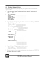
Product Support Form..................................................................................... 56
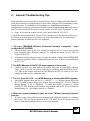
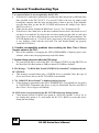
General Troubleshooting Tips......................................................................... 57
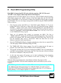
Flash BIOS Programming Utility .................................................................... 59
DC-395 Series User’s Manual
1. INTRODUCTION
The DC-395 series is a SCSI (Small Computer System Interface) bus to PCI bus host adapter,
which complies to the PCI 2.1 specification with Plug-&-Play (PnP) readiness. By using the
Disconnect/Reconnect technique, performance degradation during multitasking operations is
prevented. Other enhanced SCSI-2 features such as scatter-gather and command-tag queuing
are supported. The DC-395 series supports ASPI (Advanced SCSI Programming Interface)
managers for the following operating systems to assure operation with popular third party
applications:
• MS-DOS
• Windows 95/98/NT
• OS/2 2.0/WARP 3.0/4.0
• NetWare 3.x/4.x
Device drivers are also supported for the following major operating systems for
compatibility with a full range of SCSI peripherals including CD-ROMs, Photo CDs, tape
backups, scanners, removable media and SCSI hard drives:
• MS-DOS
• Windows NT 3.x/4.0/2000
• OS/2 2.0/WARP 3.0/4.0
• Windows 95/98
• SCO Unix 3.2v4.x & OpenServer 5.0.x
• NetWare 3.x/4.x/5.0
• UnixWare 1.1/2.1.3/7.0.1
• Solaris 2.6/7.0
• Linux
• FreeBSD
* UnixWare, SlackWare/RedHat Linux, and FreeBSD drivers can be accessed via
www.tekram.com or ftp.tekram.com/scsi.
Most SCSI Adapters require device drivers to support more than 2 hard drives under DOS.
The DC-395 series, however, provides special support to handle up to eight devices,
including fixed disks and removable media under MS-DOS 5.0/6.x, without the need for
device drivers (More than 2 drives support).
The on-board menu-driven setup and jumperless design of the DC-395 series allow you to
configure the host adapter, SCSI devices, and BIOS-related parameters without opening your
computer. The DC-395 series also provides a utility program that supports low-level
formatting. And with the help of the DOS driver installation software (INSTALL.EXE), the
drivers are easily installed and the CONFIG.SYS and AUTOEXEC.BAT files are
automatically updated.
The fully intelligent solution provided by the DC-395 PCI to SCSI Host Kit is ideal for
multitasking environments such as OS/2, NetWare, Unix, Microsoft Windows 95/98 and
Windows NT, as well as next generation operating systems such as Microsoft Windows NT
5.0.
DC-395 Series User’s Manual
5
2. HARDWARE SETUP
Static Precautions
Static electricity can be a serious danger to the electronic components on this board. To avoid
damage caused by electrostatic discharge, observe the following precautions:
ü Don’t remove the board from its anti-static packaging until you are ready to install it into
a computer case. Also, handle add-in cards and modules by the edges or mounting
bracket.
ü Before you handle the board in any way, touch a grounded, anti-static surface, such as an
unpainted portion of the system chassis, for a few seconds to discharge any built-up static
electricity.
Before plugging the DC-395 series adapter into your system, make sure all jumpers on the
card are correctly set according to the instructions outlined in section 2.2. Also take care that
the SCSI ID number (0-6 for DC-395U; 0-15 for DC-395UW/F) of each SCSI device is set
properly for the host adapter (Section 2.3).
The maximum devices that can be installed on each model are show below:
Model #
DC-395U
DC-395UW/F
Max. Devices Number
7
15 *
•
For DC-395U, up to seven 8-bit SCSI single ended (SE) devices can be connected.
•
For DC-395UW/F, up to fifteen 16-bit and/or 8-bit SCSI single ended (SE) devices can
be connected. Up to seven of these can be 8-bit. And only two of the three SCSI
connectors, either Internal or External, can be used to connect SCSI devices at any given
time.
Correct termination and cable connections are also necessary for SCSI adapters to function
properly (Section 2.4 and 2.5).
6
DC-395 Series User’s Manual
2. HARDWARE SETUP
2.1
Board Layout
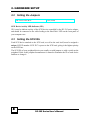
The following figures illustrate the jumper and connector locations for the DC-395 Series
PCI SCSI Host Adapters:
DC-395U
Ultra SCSI-3 adapter
DC-395UW
Ultra WideSCSI-3 adapter
DC-395 Series User’s Manual
7
2. HARDWARE SETUP
2.2
Setting the Jumpers
DC-395U/395UW/F:
JP1 (LED)
SCSI Device Activity LED Indicator (JP1)
JP1 is used to indicate activity of the SCSI devices controlled by the DC-395 series adapter,
and should be connected to the cable leading to the Hard Drive LED on the front panel of
your computer case.
2.3
Setting the SCSI IDs
Each SCSI device attached to the SCSI card, as well as the card itself, must be assigned a
unique SCSI ID number. SCSI ID 7 is preset to the SCSI card, giving it the highest priority
on the SCSI bus.
The SCSI IDs of your peripheral devices are usually set with jumpers or with a switch on the
peripheral. Refer to the peripheral manufacturer’s manual to determine the ID of each device
and how to change it.
8
DC-395 Series User’s Manual
2. HARDWARE SETUP
2.4
Checking the Terminators on the SCSI Bus
In order to stabilize the SCSI bus, only two sets of terminators can be installed - one at each
end of the SCSI bus. The DC-395 series is equipped with Active Terminators that
automatically switch from Enabled to Disabled or vice versa by scanning the devices
connected on the SCSI bus. So, manual termination adjustment is not required. The following
explains the terminator configuration of other devices on the SCSI bus:
1.
When only internal devices are connected to the DC-395 series adapter: Leave the
terminator mounted on the last device only, with the SCSI card being the first SCSI
device. Remove terminators on all other devices connected in between.
2.
When only external devices are connected to the DC-395 series adapter: Leave the
terminators mounted on the last device only. Since external SCSI devices are daisy
chained, this would be the device without another SCSI cable plugged into it. Remove
terminators on all other devices connected in between.
3.
When both internal and external devices are connected to the DC-395 series adapter:
Leave only the terminators mounted on the last internal device and the last external
device. As in the above case, remove the terminators from all other devices connected in
between.
Note1: For DC-395UW/F only: When both Narrow (8-bit) and Wide (16-bit) devices are
connected to the Wide SCSI connector (either Internal or External), arrange the
devices so that a Wide device with termination enabled is at the end of the bus. A
Narrow device at the end of the bus can have termination problems in this case,
since the Wide bus is 16-bit and the terminator on the Narrow device is only
effective for the lower 8-bit (not the whole 16-bit).
Note2: There are two types of termination available on SCSI devices, active and passive.
Active termination is strongly recommended to ensure system integrity, particularly
when devices with high transfer rates are being used. A SCSI CD-ROM drive
usually comes with a passive terminator. For proper termination, it is recommended
that you keep this terminator disabled, i.e. avoid connect the CD-ROM drive at the
end of the SCSI bus
DC-395 Series User’s Manual
9
2. HARDWARE SETUP
2.5
Cable Connection
Model #
External
Internal
DC-395U
CN1: 50-pin; 8-bit
CN2: 50-pin; 8-bit
DC-395UW*
CN1: 50-pin; 8-bit
CN2: 68-pin; 16-bit (wide)
CN3: 50-pin; 8-bit
DC-395F
CN1: 68-pin; 16-bit
CN2: 68-pin; 16-bit (wide)
CN3: 50-pin; 8-bit
* Only two of the three connectors can be used to connect SCSI devices at the same time.
External SCSI connector: This high density D-type SCSI connector is for connecting
external SCSI devices.
Internal SCSI connector: The internal flat cable should connect to the internal SCSI
connector with its colored stripe, normally red, aligned with Pin 1 of the connector.
Maximum length of the SCSI bus is determined by the number of devices and the data
transfer rate. The following table summarizes the maximum allowable cable lengths for the
DC-395 series:
Model #
SCSI Type
Data Xfer
Max. # of
Max. Cable Length
Rate
Devices
DCUltra /Ultra 20/40 MB/Sec
4
3meters (9.8 feet)
395U/UW/F
Wide SCSI
• If there are internal devices connected, the internal cable length must be included in
the measurement of SCSI bus length.
10
DC-395 Series User’s Manual
3. CONFIGURING YOUR SCSI CARD
3.1
Setting the System BIOS
After the DC-395 is inserted in an available PCI-BUS slot and the jumpers and cables are
properly set, first turn on the power to your external SCSI devices and then power on the
system. When installing a SCSI drive as drive C: (or D:), set the CMOS HDD drive type
according to the IDE drive installed. The CMOS HDD is NOT related to SCSI HDD.
Note: With most mainboards, IDE (Intelligent Drive Electronics)/ST506 and ESDI
(Enhanced Small Device Interface) drives always take precedence over SCSI drives.
That means that if one IDE/ST506/ESDI drive has already been installed, you cannot
install the SCSI drive as drive C:. If two IDE/ST506/ESDI drives already exist, no
SCSI drives can be installed as C: or D:. However, if your mainboard BIOS has
multiple boot options, such as “boot from SCSI device”, this will allow the system to
boot from any bootable SCSI device connected to the DC-395 series controller.
Since the mainboard BIOS will automatically shadow the PCI adapter’s BIOS, there is no
need to set the shadow option between C800 and DFFF. This option is for ISA adapter ROM
only. The I/O Base Address and IRQ ROM shadow addresses are also assigned by the
mainboard BIOS automatically. You do not need to worry about it. Just Plug & Play and
enjoy it.
Right after exiting the system BIOS CMOS setup, the following message will pop up and
prompt you to enter the PCI Configuration Utility to configure the card:
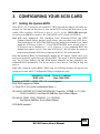
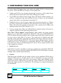
TEKRAM DC-395UW PCI-SCSI Controller
BIOS v3.00
Date: 1999-02-22
Installed at IOPORT = 6800h, IRQ =10 - Level triggered
BIOS ROM mapped at C800h
<< Press F2 or F6 to enter configuration Menu >>
ID-LUN:6-0 MICROP 2217-15MZ1001905HQ30 Fixed disk 1678MB ==> C: (80h)
C/H/S=214/253/63, Xfer Rate=20.0MB/Sec, Sync Offset=15Bytes
ID-LUN:3-0 SONY CD-R CDU924S 1.1d CD-ROM
Xfer Rate=4.0MB/Sec, Sync Offset=15Bytes
SCSI BIOS installed !
DC-395 Series User’s Manual
11
3. CONFIGURING YOUR SCSI CARD
3.2
Running the PCU (PCI Configuration Utility)
Since the DC-395 series is PCI compliant with Plug-&-Play (PnP) readiness, the system
should allocate the proper Interrupt Level, Adapter BIOS Address and other settings
automatically. Still, entering the PCU allows you to view more information and set additional
options for both the DC-395 series adapter and the SCSI Devices. Utilities for verifying bad
blocks and low level formatting are also included. Another alternative is to run the provided
DOS utility program UTIL.EXE, which performs the same functions as the PCU does.
Note:
UTIL.EXE may be the only way to change options in the configuration of DC-395
series adapter in the event that either a) The DC-395’s BIOS is disabled OR b) The
option “F2 or F6 Function During Bootup” is disabled. It also allows you to modify
your settings without rebooting to enter the PCU. When running UTIL.EXE, it’s best
to boot clean from a DOS floppy disk.
After powering up the system, the DC-395's BIOS will show a message indicating its BIOS
version with a date code and information about the IOPORT address, IRQ number and
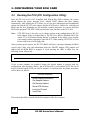
address that the ROM BIOS is mapped at. Upon pressing the <F2> or <F6> key, the
following screen will pop up:
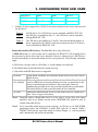
Select An Adapter To Setup
DC-395U/UW/F or DC-315/U
BUS#00
DEV#0C
IOPORT = 9600h
IRQ = 11
If two or more adapters are installed, choose the desired adapter to proceed with the
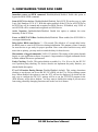
configuration. After pressing <Enter>, the SCSI bus will be reset and the SCSI IDs for all
devices installed on the SCSI bus will be scanned. A selection table for further operations
will be shown as follows:
Function Selection
Show Adapter Information
Set Adapter Options
Set Devices Options
Show SCSI Devices
Low Level Format
Verify Disk
The sections that follow contain detailed descriptions of the above options.
12
DC-395 Series User’s Manual
3. CONFIGURING YOUR SCSI CARD
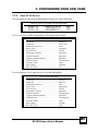
3.2.1 Show Adapter Information
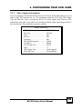
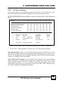
This screen displays detailed information about the SCSI chip, ROM BIOS address, I/O port
address, IRQ, PCI interrupt line, etc. The information about the SCSI Chip, IRQ Trigger
Type and Data Xfer Type is provided by the DC-395 series adapter itself. The rest of the
information in this table is provided by the mainboard's BIOS, which should support the PCI
PnP specification. This information cannot be modified.
Adapter Information
SCSI Chip …………………...
Bus Type …………………….
Bus# …………………………
Device# ……………………...
Function# …………………….
BIOS ROM mapped at ……...
IO Address …………………..
PCI Interrupt Line …………..
IRQ# ………………………...
IRQ Trigger Type …………...
Data Xfer Type ……………...
TRM-S1040
PCI Bus
00h
08h
00h
C800h
D800h
INTA#
11
Level triggered
PCI Bus Master
DC-395 Series User’s Manual
13
3. CONFIGURING YOUR SCSI CARD
3.2.2 Set Adapter Options
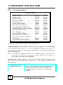
Set Adapter Options
Adapter SCSI ID ……………………….
Boot Device ID …………………………
Boot Device LUN ……………………...
Boot From CD-ROM …………………..
INT13 Extension ………………………
Greater Than 1G Support ……………...
More Than 2 Drives Support …………
Removable Media as BIOS Device ….
Immediate Return on SEEK Command…
Scan All LUN For Devices……………
Active Negation ………………………..
Power on RESET SCSI Bus …………..
Delay Before BIOS scans device ………
Max Number of Tagged Commands …
Parity Check ….……………………..
F2 or F6 Function During Bootup …….
SCSI ID 7
SCSI ID 0
LUN 0
Disabled
Enabled
Enabled
Enabled
Boot only
Disabled
Disabled
Enabled
Enabled
3 sec
32
Enabled
Enabled
-- Default
-- Default
-- Default
-- Default
-- Default
-- Default
-- Default
-- Default
-- Default
-- Default
-- Default
-- Default
-- Default
-- Default
-- Default
-- Default
Pressing <F8> will reset all the settings to their default values.
Adapter SCSI ID: 0-7. The default ID for the DC-395 series adapter is 7. It is recommended
not to change this default value of 7, as it gives the adapter the highest priority on the SCSI
bus. However, if you have two adapters on the same SCSI bus, you should give one of them a
currently unassigned ID.
Note: For DC-395UW, sixteen SCSI IDs 0-15 are available. If there is any 8-bit device
connected on the SCSI bus, avoid setting the adapter SCSI ID to the number 8 or
larger otherwise you may run into difficulties.
Boot Device ID: SCSI ID 0 (default) – 7 (DC-395U) or 15 (DC-395UW). This option allows
you to boot from any bootable devices connected. To ensure proper operation, see the
following notes:
• If a bootable IDE drive is
installed in the system:
14
The IDE drive will boot by default before any SCSI
devices. This is a function of the mainboard’s BIOS. To
boot from a SCSI device in this case, a setting in the
mainboard BIOS such as “Boot From SCSI” must be
available.
DC-395 Series User’s Manual
3. CONFIGURING YOUR SCSI CARD
• Booting from a removable
SCSI device:
The above applies. Also, the setting Removable media as
BIOS device (see page 17) should be set to “Boot drive
only” *
• Booting from a SCSI CDROM:
The setting Boot From CD-ROM (see below) must be
“Enabled” (for CD-Changer, Boot Device LUN may need
additional configuration). This setting takes precedence
over the boot device setting in the mainboard’s BIOS.
(*) Since removable media with 2048 Byte/sector is not supported by the system BIOS,
this type of media won’t be accepted as a Bootable device by the system.
Boot Device LUN: LUN 0 (default) - 7. If the SCSI device you wish to boot from has a LUN
number other than 0, this option must be set for the specific LUN number in addition to
setting the Boot Device ID for the SCSI ID number.
Boot From CD-ROM: Disabled/Enabled. When enabled, the option will be given to boot
from CD-ROMs detected by the controller as bootable. This setting takes precedence over
any settings in the mainboard BIOS such as “boot from IDE”. The Boot Device ID and Boot
Device LUN (if LUN is not 0) settings can be adjusted to ensure proper operation. If these
options are left on the default, the bootable CD-ROM with the lowest SCSI ID / LUN number
will boot if there is more than one bootable CD-ROM.
Note: Don’t confuse these settings with the “Boot From CD-ROM” option in the
mainboard’s BIOS setup, which is relevant only to ATAPI CD-ROMs.
INT13 Extension: Enabled (default)/Disabled. When enabled, the DC-395 will support more
than 1024 cylinders for use with operating systems supporting the INT13 Extension. The
conventional INT 13H disk interface supports a maximum of only 1024 cylinders. For
operating systems such as Win95 OSR2 or later, supporting INT13 Extension, the DC-395
will support >1024 cylinders by using the Command Packet Mechanism instead of the
cylinder/head/sector mechanism and thus work with SCSI disks greater than 8GB.
•
For operating systems not supporting the INT13 Extension this option will be ignored.
•
This setting is not to be confused with Greater Than 1GB Support, which simply remaps
the device’s parameters to compensate for the 1024 cylinder limit. Greater Than 1GB
Support can handle drives up to 8GB in size due to fact that the maximum
cylinders/heads/sectors is 1024/255/63 = 8GB. INT13 Extension supports drives beyond
8GB in supported operating systems by using the Command Packet Mechanism.
Greater Than 1G Support: Enabled/Disabled. FAT (File Allocation Table) file system
Operating Systems such as DOS have traditionally imposed a barrier on the number of
cylinders supported (1024). The option "Greater Than 1GB Support" in the Tekram BIOS
should be enabled if any device has more than 1024 cylinders IF you are using a FAT file
system (DOS, Windows 3.X, Windows 95). Some Operating Systems such as OS/2 and
Windows NT can use either FAT or HPFS/NTFS respectively. For these Operating Systems,
DC-395 Series User’s Manual
15
3. CONFIGURING YOUR SCSI CARD
the Greater Than 1GB Support feature only needs to be enabled if FAT is to be used as the
file system. *NTFS and HPFS do not impose a 1024 cylinder limit.
•
NetWare and UNIX are two Operating Systems that do not have a 1024 cylinder barrier
and therefore do not require that Greater Than 1GB Support be enabled.
•
If your HDD was formatted without Greater Than 1GB Support enabled originally, you
will have to backup the data and re-FDISK the drive in order to use the maximum
capacity under DOS or any Operating System using FAT.
•
Enabling the Greater than 1G support option will reassign the parameters to 512Bytes
per Sector, 63Sectors and 255Heads for SCSI disk drives with a capacity larger than 1
GByte. This allows the operation of hard drives with a capacity up to 8GByte with
operating systems such as DOS, Windows 95, etc.
•
For drives smaller than 1GByte, the 64Head/32Sector translation scheme will always be
employed, regardless of this option being enabled or not.
More Than 2 Drives Support: Enabled/Disabled. When enabled, this option provides
support of up to eight devices (controlled by BIOS INT 13H), such as IDE/ESDI/ST506/
SCSI fixed disks, removable cartridges, and re-writable optical disks (MO) without the need
for device drivers under DOS 5.0 or above. This setting may be disabled under other
operating systems than DOS. Under DOS environments, the devices connected to the DC395 can be controlled through BIOS INT 13H or device drivers. When the option “Included
in BIOS Scan” is set to Yes, that device is controlled by BIOS INT 13H. If this option is set
to No, that device must be controlled through device drivers. The two options for More Than
2 Drive Support are as follows:
•
Enabled (default)
Under DOS 5.0 or above, the ability to control up to eight devices, controlled by BIOS INT
13H is provided. Devices controlled could be IDE/ESDI/ST506/SCSI fixed disks, removable
cartridges, and re-writable optical disks (MO).
•
Disabled
When this option is disabled, only the number of drives in your mainboard CMOS setup is
supported without drivers. All other devices such as fixed disks (over two), removable
cartridges, re-writable optical disks (MO), tape streamers, DATs, and CD-ROMs, would
require device drivers. When devices are under the control of BIOS INT 13H, IDE drives
always have higher priorities over SCSI drives. The following is an example describing all
the combinations:
16
Device
Case 0
Case 1
Case 2
IDE HDD 0
none
Drive C:
Drive C:
DC-395 Series User’s Manual
3. CONFIGURING YOUR SCSI CARD
*
IDE HDD 1
none
None
Drive D:
SCSI Device 0
Drive C:
Drive D:
(*)
SCSI Device 1
Drive D:
(*)
(*)
Number of drives supported by CMOS (2) has been reached. Device driver must be used
for this device.
Case 0:
Case 1:
Case 2:
No IDE drives. Two SCSI drives can be controlled with BIOS INT 13H.
One IDE drive is installed as drive C:. One SCSI drive can be controlled
through BIOS INT 13H.
Two IDE drives are installed as C: and D:. Since the maximum number of
drives supported by the CMOS (2) has been reached, no more SCSI device
can be controlled by BIOS INT 13H.
Removable media as BIOS device: Disabled/Boot drive only/All devices.
A BIOS device here is a device that can be controlled via BIOS INT 13H, meaning that it
does not need a device driver and can be bootable. However, when used as a BIOS device,
the full removability of removable media devices is not preserved. The following constraints
apply:
a) The Device can only work as a fixed disk, i.e. media change is not allowed.
b) The Media must be inserted before the system boots-up.
c) Only media with 512 Bytes/sector is supported.
Disabled
Boot drive
only (default)
All Disks
If this option is disabled, the removable media devices will not be used as
BIOS devices.
This setting allows only the removable media installed as Drive C: to
work as a BIOS device, thereby allowing it to boot. As stated above, this
device would function as a hard drive, not a removable. However,
installing the provided device driver on this bootable drive would enable
full removability for other removable media devices installed.
Enables all removable disk drives to work as BIOS devices. Enable More
than 2 drives support if necessary.
Note1: Generally, unless a Removable device is to be used as a boot drive, this setting
should be kept at its default, and the driver TRMDISK.SYS should be used to
control removable devices.
Note2: For a removable media device to boot properly, you’ll have to use DOS FDISK
partitioning utility and FORMAT it under DOS with the /S switch. Win95’s
FORMAT will treat the removable media as a Super Floppy, i.e., with no partition
table, and thus the disk will not be bootable.
DC-395 Series User’s Manual
17
3. CONFIGURING YOUR SCSI CARD
Immediate return on SEEK command: Disabled(default)/Enabled. Enable this option to
bypass the BIOS SEEK command.
Scan all LUN for devices: Disabled(default)/Enabled. Each SCSI ID can have up to eight
Logic Unit Numbers (LUN: 0-7). With this option enabled, all the LUNs for all SCSI IDs on
the SCSI bus will be scanned and recognized as BIOS Devices. If Disabled, only LUN0 of
each SCSI ID will be scanned and recognized as a BIOS device.
Active Negation: Enabled(default)/Disabled. Enable this option to enhance the noise
immunity on the SCSI bus.
Power on RESET SCSI Bus: Enabled(default)/Disabled. When enabled, the SCSI BIOS is
reset upon initialization.
Delay before BIOS scans Device: 3 - 120 seconds. The default is a 3-second delay before
the BIOS starts to scan for SCSI devices during initialization. This amount of time is enough
for most devices to get ready for proper operation. Since some older hard drives may need
more time to spin up, you may need to extend the delay for those devices.
Max number of tagged commands: 2/4/8/16/32 (default). The setting of this option depends
largely on your application software. In general, a larger number of tagged commands results
in better random disk access performance.
Parity Checking: Yes/No. This option defaults to enabled, i.e., Yes. If set to No, the DC-395
won’t perform parity checking. For devices that do not implement the parity function, you
should disable this option.
F2 or F6 Function During Bootup: Disabled/Enabled (default). This setting determines
whether or not the user can access the DC-395’s BIOS via the F2 or F6 keys during system
boot. When disabled, the option to enter the PCU will not be displayed, in which case the
only way to configure the DC-395’s settings will be to run the UTIL.EXE program in the
\DOS directory on the driver diskette. You may want to disable this setting to prevent users
from using potentially damaging functions such as the low-level format.
18
DC-395 Series User’s Manual
3. CONFIGURING YOUR SCSI CARD
3.2.3 Set Devices Options
This sub-menu allows you to change options for each device on the SCSI bus. Device
information related to each SCSI ID is displayed in the lower portion of the screen.
DC-395U/395UW/395F: MaxSyncXferRate replaced with MaxSyncXfers. Wide Negotiation
added:
SCSI ID
#0
#1
#2
#3
#4
#5
#6
#7
Allow Disconnection
Send START UNIT Command
Tagged Command Queuing
Wide Negotiation
Synchronous Negotiation
Max Sync Xfers
Included in BIOS Scan
No
No
Yes
Yes
Yes
20.0
Yes
Yes
No
Yes
Yes
Yes
20.0
Yes
Yes
No
Yes
Yes
Yes
20.0
Yes
Yes
No
Yes
Yes
Yes
20.0
Yes
Yes
No
Yes
Yes
Yes
20.0
Yes
Yes
No
Yes
Yes
Yes
20.0
Yes
Yes
No
Yes
Yes
Yes
20.0
Yes
Yes
No
Yes
Yes
Yes
20.0
Yes
SCSI ID
0
1
2
3
4
5
6
7
Model
SEAGATE
ST31230W
FUJITSU
M2513A
SONY
CD-R
CDU924S
NEC
CD-ROM DRIVE:462
IOMEGA
ZIP 100
Device Type
Fixed disk
Optical disk
CD-ROM
CD-ROM
Removable disk
WANGTEK
Tape drive
5525ES SCSI M74H
Capacity
1010 M
604 M
121 M
95 M
*
For DC-395UW: Press <Tab> to see the next screen for SCSI ID 8-15, if available.
*
For DC-395U: "Wide Negotiation" is always set to “No” and cannot be changed.
Allow Disconnection: Yes/No. Yes is the default option and allows a SCSI device to go offline, thereby freeing the SCSI bus when performing multi-tasking operations. In this way, the
DC-395 can simultaneously process multiple operations on the SCSI bus and thus improve
efficiency in a multiple device environment.
Send START UNIT Command: Yes/No (default). Some specific drives require additional
spin-up commands to start their motors during system initialization. These devices would
require that this setting be set to Yes. However, most drives will spin up their motors
automatically during power up, and would not require the START UNIT Command. Some
drives have a jumper to enable/disable this option.
DC-395 Series User’s Manual
19
3. CONFIGURING YOUR SCSI CARD
Note:
Enabling this feature would reduce the load on your computer's power supply by
allowing the DC-395 to turn on SCSI devices one at a time during system
initialization, starting from the lowest SCSI ID. However, each device would be
required to support this option.
Tagged Command Queuing: Yes/No (default). The Yes option is useful for enhancing
overall system performance under multi-tasking operating systems such as OS/2, Windows
NT and Unix.
Wide Negotiation: Yes/No. This option is ignored when the DC-395U, a non-Wide SCSI
adapter, is installed. It is suggested that you enable this option, i.e., Yes, for 16-bit Wide
SCSI devices in order to gain the best performance and that you disable it for 8-bit devices
for less compatibility problems.
Synchronous Negotiation: Yes/No. Yes (default) is for Active Synchronous Negotiation. In
this mode the DC-395 series adapter will initiate SCSI synchronous negotiation when the
system boots up. NO, Asynchronous Negotiation mode, is normally at a lower rate and not
related to timing.
MAX Sync Xfer Rate : 20.0 - 40.0 MB/sec. . The DC-395’s will negotiate an optimum
speed depending on the transfer rate of each device under the chosen option.
MAX Sync Xfers (for DC-395U/395UW):
Model #
DC-395U
DC-395UW
SCSI
width
Byte/Xfer
Max Sync Xfer
(MXfer/sec)
8-bit
1
20
16-bit
2
40
Included In BIOS Scan: Yes (default)/No. When set to Yes, the DC-395’s BIOS will scan
and display the device’s information during system bootup. HDD scanned by the BIOS will
be controlled by BIOS INT 13H (See More Than 2 Drives Support). When set to No, the DC395’s will not scan the device and device drivers will be needed to control it.
You may set this option to No for SCSI ID(s) without device(s) connected to speed up the
device scanning during boot. But, beware that any connected device will not be scanned and
recognized by the BIOS when this option is set to No. So, if any connected devices are not
presented in DC-395’s BIOS display message during bootup, check this option first.
20
DC-395 Series User’s Manual
3. CONFIGURING YOUR SCSI CARD
3.2.4 Show SCSI Devices
This sub-menu provides general information for all devices on the SCSI bus:
Select A Device For Display Device Information
ID-LUN 0-0
ID-LUN 1-0
ID-LUN 4-0
SEAGATE ST32171N
FUJITSU M2513A
IMPRIMIS94241-7
0280
1000
1275
You can see more detailed information by selecting the desired drive:
SCSI Device Information
Vender ID …………………………………
Product ID ………………………….….….
Product Revision level ………………….
Device Type ………………………………
SCSI Version ……………………………..
Synchronous Transfer …………………..
Linked Command …………………………
Tagged Command Queuing …………….
SCAM Protocol …………….…………….
SCSI Bus Width ………………………….
Disk Capacity ……………………………..
Bytes Per Sector …………………………..
SEAGATE
ST32171N
0820
Fixed disk
SCSI-II
Supported
Supported
Supported
Not Supported
8 Bits
2061MB
512
You can then move on to other drives to view their information:
SCSI Device Information
Vender ID …………………………………
Product ID ………………………….….….
Product Revision level ………………….
Device Type ………………………………
SCSI Version ……………………………..
Synchronous Transfer …………………..
Linked Command …………………………
Tagged Command Queuing …………….
SCAM Protocol …………….…………….
SCSI Bus Width ………………………….
Disk Capacity ……………………………..
Bytes Per Sector …………………………..
FUJITSU
M2513A
1000
Optical disk
SCSI-II
Supported
Not Supported
Supported
Not Supported
8 Bits
604 MB
2048
DC-395 Series User’s Manual
21
3. CONFIGURING YOUR SCSI CARD
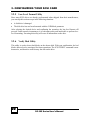
3.2.5 Low Level Format Utility
Since most SCSI drives are already pre-formatted when shipped from their manufacturers,
you can skip this section except in the following situations:
•
A disk drive is damaged
•
The disk drive has not been formatted with the 512B/block parameter
After selecting the desired device and confirming the operation, the low-level format will
proceed. Under normal circumstances, it is both unnecessary and inadvisable to perform lowlevel formatting. Executing this utility will erase all information on the drive.
3.2.6 Verify Disk Utility
This utility is used to detect bad blocks on the chosen disk. With your confirmation, the bad
blocks detected can be reassigned for future operations. The SCSI VERIFY command is nondestructive, and therefore won't destroy the data on the drive.
22
DC-395 Series User’s Manual
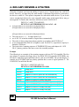
4. DOS ASPI DRIVERS & UTILITIES
This chapter describes in detail the various ASPI Drivers and Utility programs that are
provided with the DC-395 Host Adapter Kit for use under the DOS operating system. To get
up and running quickly under DOS, see Section 4.1 - Easy DOS Driver Installation
Software for easy installation instructions.
The major ASPI Drivers and Utilities are:
•
T3X5ASPI.SYS: The ASPI (Advanced SCSI Programming Interface) driver that
provides the basic communication interface for the host adapter and the DOS operating
system. It supports up to four coexisting host adapters, and is compatible with peripheral
drivers for Sytos (Plus), ARCserve/Solo tape subsystems, fixed disks, removable
cartridges, MO drives, Flopticals, CD-ROMs, CD-Changers and Scanners.
•
TRMDISK.SYS: This driver is for controlling those SCSI devices not supported by BIOS
INT 13H (See More Than 2 Drives Support and Included in BIOS Scan). These devices
would primarily be fixed disks, removable cartridges, re-writable optical disks (MO) and
flopticals. It allows the creation of valid partitions on these devices for use as logical
drives, and also recognizes data formats used by other adapter manufacturers.
•
TRMCD.SYS: The device driver for CD-ROM and CD-Changer devices. This driver is
loaded after T3X5ASPI.SYS in the CONFIG.SYS file.
•
TFDISK.EXE: A DOS-compatible disk partitioning utility program for SCSI hard disks,
removable media, and magneto-optical drives that are not managed by the BIOS of the
DC-395’s (Those managed by TRMDISK.SYS).
•
UTIL.EXE: Allows configuration of the PCU from DOS (as opposed to re-booting the
system and pressing the <F2> key).
DOS uses the ASPI manager as a software interface to communicate with SCSI devices. The
specific peripheral driver then talks to the ASPI interface instead of the host adapter
hardware. Under this architecture, multiple devices can share the host adapter without
conflict. The ASPI driver is typically installed under the following situations:
•
Multiple adapters coexist (up to four)
•
SCSI devices not controlled by BIOS INT 13H are installed (CD-ROMs)
•
Devices that use removable media are installed
•
An interface to Tape Drives, CD-ROMs and other SCSI devices is needed
Example: You could operate 7 SCSI Hard Disks under MS-DOS with no ASPI drivers
loaded, as long as More Than 2 Drives Support is Enabled. If you were to add a
CD-ROM or tape drive, however, you would need to install the ASPI drivers.
DC-395 Series User’s Manual
23
4. DOS ASPI DRIVERS & UTILITIES
4.1
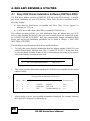
Easy DOS Driver Installation Software (INSTALL.EXE)
The DOS driver diskette provides an INSTALL.EXE file in the \DOS directory to provide
easy driver installation for your SCSI devices. Under DOS, the driver installation will be
necessary if either:
a) More than two Hard Drives are installed and "More Than 2 Drives Support" is
disabled (sec.3.2.2), or
b) A SCSI device other than a Hard Drive is installed (CD-ROM, etc.)
This software program provides you with information about the adapter and your SCSI
devices. After choosing the device(s) that you want to install drivers for, Install will update
the CONFIG.SYS and AUTOEXEC. BAT files automatically. Further information about
drivers and step-by-step installation procedures can be found in Chapter 3: DOS ASPI
DRIVERS & UTILITIES.
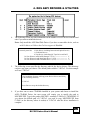
The following screens illustrate the DOS driver install procedure:
1.
To begin, this screen displays information about the adapter number (HA#0), I/O port
address (Base E400H), interrupt level (IRQ 11), and SCSI ID (ID 7). In this case, there
is only one adapter installed. If there are two or more adapters coexisting in your system,
select which adapter you want to work with.
The system has the following Host Adapter(s)
1
2.
DC-3x5 HA#0 Base E400H
IRQ 11 ID7
This screen provides information regarding the SCSI devices controlled by the chosen
adapter (HA#0).
The system has the following SCSI devices:
3.
Dev#
HA#
SCSI ID#
Vendor ID
Product ID
Revision Level
0
1
2
0
0
0
0
1
3
FUJITSU
MAXTOR
NEC
M2614S
LXT-200S
CD-ROM DRIVE: 04
0607
2.11
1.0
After selecting a device, more detailed information is displayed. For example, selecting
the Fujitsu drive brings up a window like so:
24
DC-395 Series User’s Manual
4. DOS ASPI DRIVERS & UTILITIES
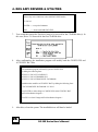
4.
The following screen provides information on the number of SCSI devices installed and
asks if you want to install the drivers:
Note: Only install the ASPI Hard Disk Driver if you have a removable device, such as
an M.O. drive, or if More than 2 drives support is Disabled.
Current System Has
2 Disk Drives (including Removal and Optical Device)
1 CD-ROM Devices
0 Tape Device (including QIC Tape Drive and DAT)
Do You Want to install ASPI Manager ? (Y/N) ----------------------- Y
Do You Want to install Hard Disk Driver ? (Y/N) -------------------- Y
Do You Want to install CD-ROM Driver ? (Y/N) --------------------- Y
5.
The following screen specifies the directory path for the device drivers. This directory
can have any name you choose. The default path would be C:\DC3x5 . For this example
we'll use C:\DC3x5:
This Installation Program will copy some Device Drivers and Utility
to the following directory
C:\DC3x5
Press Enter to accept the default directory
6.
If you have one or more CD-ROMs installed in your system and choose to install the
ASPI CD-ROM Driver, the next screen will require you to specify the path to
MSCDEX.EXE. Type in the path to MSCDEX - normally C:\DOS or C:\WINDOWS. If
you choose the default path of C:\DC3x5, you need to copy MSCDEX.EXE from
C:\DOS (or the directory where it resides) to C:\DC3x5 after the driver installation is
complete.
DC-395 Series User’s Manual
25
4. DOS ASPI DRIVERS & UTILITIES
Please Key in the PathName where MSCDEX.EXE Resides
C:\DC3x5
ENTER ---- Accept the Pathname
ESC
---- Abort Install MSCDEX.EXE
7.
You would then assign the first drive letter to be reserved for the CD-ROM drive(s). In
this case, Drive: F is reserved for the first CD-ROM drive:
8.
After confirmation, the installation program will modify both the CONFIG.SYS and
AUTOEXEC.BAT files.
This installation program will modify system CONFIG.SYS
by adding the following lines:
DEVICE=C:\DC3x5\T3x5ASPI.SYS
DEVICE=C:\DC3x5\TRMDISK.SYS
DEVICE=C:\DC3x5\TRMCD.EXE /D:CDROM0
Installation also modifies AUTOEXEC.BAT by adding the following lines:
C:\DC3x5\MSCDEX /D:CDROM0 /L:F /M:12
Press ENTER to make change to CONFIG.SYS and AUTOEXEC.BAT
and Exit Installation Program !
Press ESC to Abort Change and Exit Installation Program !
9.
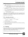
After this, re-boot the system. The installed drivers will then be loaded.
26
DC-395 Series User’s Manual
4. DOS ASPI DRIVERS & UTILITIES
4.2
Installing the ASPI Driver
With the ASPI driver ASPI.SYS installed, you are able to run or install the following utilities
and drivers:
•
TFDISK.EXE: Disk partitioning utility on the DC-3x5 series driver diskette
•
TRMDISK.SYS: Disk driver on the DC-3x5 series driver diskette
•
AFDISK.EXE: Disk partitioning utility from Adaptec
•
ASPIDISK.SYS: Disk driver from Adaptec
•
TRMCD.SYS: CD-ROM and CD-Changer driver on the DC-3x5 driver diskette
•
SYTOS PLUS: Tape backup program from SYTRON CORP.
•
SYTOS V3.x: Tape backup program from SYTRON CORP.
•
ARCserve/Solo: Tape backup program from Cheyenne CORP.
Other utilities/drivers that conform to the ASPI standard may also be used.
Installation Procedure
1.
Turn on the system and boot into DOS.
2.
Insert the DC-395 Driver Disk1 into your floppy drive.
3.
Copy the drivers and utilities into a properly named directory, e.g., C:\ASPI.
4.
Add a line in the CONFIG.SYS:
DEVICE=C:\ASPI\T3x5ASPI.SYS
4.3
Installing the TRMDISK.SYS Driver
TRMDISK.SYS is used to create valid DOS partitions and logical drives with those disks not
controlled by BIOS INT 13H. Generally, this driver is needed only for Removable devices.
Remember, by default Hard Drives are controlled by BIOS INT 13H (More Than 2 Drives
Support Enabled), whereas removable devices are not controlled by BIOS INT 13H
(Removable Media as BIOS Device Disabled).
TRMDISK.SYS controls up to eight SCSI devices, such as fixed disks, removable cartridges,
re-writable optical disks and Flopticals. Since TRMDISK.SYS automatically scans the
parameters from the master boot record of your drives, it is possible to install drives
previously used with other SCSI adapters without any inconsistency.
DC-395 Series User’s Manual
27
4. DOS ASPI DRIVERS & UTILITIES
Using the /d option, you have the ability to reserve up to 9 logical drives for each SCSI
device. However, you must keep the total number of partitions (logical drives) reserved by
the driver to within 16. This option is important for removable media devices. If you do not
reserve enough logical drives for your removable media, some of the logical drives may go
unrecognized. To install, add a line after ASPI driver in the CONFIG.SYS:
•
•
•
•
•
•
DEVICE=C:\ASPI\ T3X5ASPI.SYS
DEVICE=C:\ASPI\TRMDISK.SYS /d n1 n2 n3 ... n8
n1 logical drives are reserved for 1st physical drive
n2 logical drives are reserved for 2nd physical drive
.
.
n8 logical drives are reserved for 8th physical drive
The value of nx (x = 1 .. 8) ranges from 0 to 9
nx=0: DC-395 scans the number of logical drives automatically
The order of drives starts from primary partition to secondary and SCSI ID 0 to 7
It is recommended that DOS 4.x or higher be used. For DOS 3.x, logical drive capacity is
limited to 32M bytes.
The logical drive scanning sequence of TRMDISK.SYS starts with adapter #0 - SCSI
ID=0 - primary partition, then moves on to the extended partition.
Example
The following is an example of the scanning sequence with two DC-395s installed. The first
one (adapter 0) controls two floppy drives, two BIOS INT 13H controlled SCSI HDDs, one
MO device with three logical partitions (drives), and one SCSI HDD. The second adapter (1)
controls one SCSI HDD with one primary partition that is seen as logical partition G:. The
CONFIG.SYS would look like this:
DEVICE=C:\ASPI\T3X5ASPI.SYS
DEVICE=C:\ASPI\TRMDISK.SYS /d300
28
Drive A:
Floppy drive
Drive B:
Floppy drive
Drive C:
Adapter 0, SCSI ID 0 (BIOS INT13h controlled HD)
Drive D:
Adapter 0, SCSI ID 1 (BIOS INT13h controlled HD)
Drive E:
Adapter 0, SCSI ID 4, Primary DOS (MO)
Drive F:
Adapter 0, SCSI ID 4, Extended DOS Logical drive (MO)
Drive G:
Adapter 0, SCSI ID 4, Extended DOS Logical drive (MO)
Drive H:
Adapter 0, SCSI ID 5, Primary DOS (HD)
Drive I:
Adapter 1, SCSI ID 2, Primary DOS (HD)
DC-395 Series User’s Manual
4. DOS ASPI DRIVERS & UTILITIES
Note:
With the More Than 2 Drives Support option enabled in the PCU, you will be able
to install up to eight drives without installing device drivers. Of course, your DOS
version must be 5.0 or higher.
LOCK/UNLOCK functions are crucial for data integrity of removable devices and need to be
supported by drivers. To prevent the data from being destroyed by improper operation of
your devices, it is recommended to use the DOS 4.x or higher SHARE utility for automatic
LOCK/UNLOCK support. This can be done by adding SHARE.EXE to your
AUTOEXEC.BAT file. After loading share.exe, the system will LOCK your media when
opening a file and UNLOCK it when closing the file. This means that removable media can
be ejected and changed at any time as long as no file is opened. This change is transparent to
the user, and DOS logical drive information will be updated automatically every time the
cartridge is changed.
4.4
Disk Partition Utility
TFDISK.EXE is a disk-partitioning program for modifying or creating partition tables under
DOS. Valid DOS partitions can be created by DOS FDISK only for drives controlled by
BIOS INT 13H. Drives controlled by TRMDISK.SYS must use TFDISK.EXE. After you
partition a disk device with TFDISK you must also run the DOS FORMAT command on the
device before you can use it. To run this program, you have to install the ASPI drivers first,
then add a line after ASPI driver, i.e., add two lines to the CONFIG.SYS file:
DEVICE=C:\ASPI\ T3X5ASPI.SYS
DEVICE=C:\ASPI\TRMDISK.SYS
To partition a disk, simply type TFDISK.EXE at the DOS prompt (NOT the MS-DOS
Prompt under Windows). Two translation methods are available, depending on the disk
space: <1GB or >1GB.
• <1GB Translation
Method:
Heads = 64
Sectors = 32
Cylinders= XXX - Depends on drive’s capacity.
• >1GB Translation
Method:
Two methods available:
•
Using default disk parameters:
This method reads and uses the parameters from the master boot
record of drives used previously with other adapters. If no
previous settings are available, the 64Head/32 Sector parameter
scheme is used.
Heads = 64
Sectors = 32
DC-395 Series User’s Manual
29
4. DOS ASPI DRIVERS & UTILITIES
Cylinders= XXX – Depends on drive’s capacity.
•
Using 255 heads, 63 sectors parameters:
Heads = 255
Sectors = 63
Cylinders = XXX – Depends on drive’s capacity.
After partitioning the disk, you must also choose "Create Logical Drive" to assign a DOS
drive letter to the partition. Then, exit and re-boot the system.
4.5
Installing the CD-ROM Driver
TRMCD.SYS is the driver for CD-ROM and CD-Changer devices. To enable a CD-ROM
under DOS, you will also need MSCDEX.EXE, which is supplied with MS-DOS 6.0 or
higher. This program can be acquired from Microsoft separately.
1. Add a line after the ASPI driver,
DEVICE = C:\ASPI\ T3X5ASPI.SYS
DEVICE = C:\ASPI\TRMCD.SYS /d:cdrom0
Note 1: For Trantor's Music Box, you have to add one more option as follows:
DEVICE= C:\ASPI\TRMCD.SYS /d:cdrom0 /mb
Note 2: If your CD-ROM is compatible with another manufacturer and not recognized,
you have to add one more option /t:XXX, XXX: Short for compatible
manufacturer name. For example: If your DEC CD-ROM CDU-541 is compatible
with the SONY CDU-541 and not recognized by the previous command, you can
try to add the following option:
DEVICE= C:\ASPI\TRMCD.SYS /d:cdrom0 /t:SON
2. Add a line in the AUTOEXEC.BAT file:
C:\DOS\MSCDEX.EXE /d:cdrom0 /m:12
Note:
30
In the above example, C:\DOS is the directory containing the file
MSCDEX.EXE.
DC-395 Series User’s Manual
4. DOS ASPI DRIVERS & UTILITIES
4.6
Installing Tape Streamer (DAT)
After installing the ASPI.SYS driver, the DC-395 can support the following tape backup
subsystems under DOS.
•
SYTOS PLUS Tape backup program from SYTRON CORP.
•
SYTOS V3.xTape backup program from SYTRON CORP.
•
ARCserve/SoloTape backup program from Cheyenne CORP.
Note that the ASPI driver only provides the interface for tape systems. You must purchase
the desired tape backup software program separately.
DC-395 Series User’s Manual
31
5. NETWARE DRIVERS
The DC-395 supports drivers for NetWare V3.12/SFT-III/4.00/4.01/4.02/4.1x/4.2/4.2SB/5.0.
These are located under same directory on the software diskette:
This directory contains the following drivers :
•
DC3X5.HAM supports SCSI devices, such as Fixed Disks, Removable Cartridges, and
Re-writable Optical Disks (MO), and provides an interface to the ASPITRAN.DSK
module
•
DC-3X5.DDI is the driver definition information file that provides setup information to
NetWare during installation.
32
DC-395 Series User’s Manual
5. NETWARE DRIVERS
5.1
ASPI Drivers for NetWare
5.1.1 NetWare 5.0
This subsection explains major installation procedures for NetWare Versions 5.0:
1.
Begin the file server installation according to the instructions in the file server
installation chapter in the Novell NetWare installation manual.
2.
After seeing a message showing "Device types” and “Driver names” during the
installation, select “Modify” option and press “Enter” key.
3.
Insert the DC3X5 device drivers diskette into drive A: or B: ,press “Ins” key.
4.
Then use the “Ins” key to select an unlisted driver. If the driver diskette is in drive A:,
press “Enter” key to continue. If the driver diskette is in the B: drive, press the <F3>
key to specify the path: B:\NETWARE, and press <Enter> key to load this driver.
You will find DC3X5.HAM in the “Driver names” list. Follow the NetWare Installation to
complete the procedure.
5.1.2 NetWare 4.xx
This subsection explains major installation procedures for NetWare Versions 4.00/4.01/
4.02/4.1x/4.2/4.2SB:
1. Begin the file server installation according to the instructions in the file server installation
chapter in the Novell NetWare installation manual.
2. After seeing a message block showing "Choose the server Drivers - Disk Driver" during
the installation, insert the DC3X5 device drivers diskette into drive A: or B: . Then use the
“Ins” key to select an unlisted driver. A dialog box will appear. If the driver diskette is in
drive A:, press “Enter” key to continue. If the driver diskette is in the B: drive, press the
<F3> key to specify the path: B:\NETWARE, and press <Enter> key to load this driver. The
DC-3X5.HAM driver will appear as a selection.
3.
Load a separate instance of the driver for every Host adapter present in the system.
4. The install program will then require you to install additional server drivers. You may see
a message stating that the driver did not load in the time allowed. Following that, you should
see a message like that below:
LOAD C:\NWSERVER\DC3X5.HAM
Loading module DC3X5.HAM
DC-395 Series User’s Manual
33
5. NETWARE DRIVERS
DC-395U/UW/F or DC-315(U) PCI SCSI Adapter Driver For NetWare
V3.12/V4.xx/5.0
Version 3.0 February 22, 1999
Tekram Technology Co.,Ltd.
Auto-loading module NWPA.NLM
NetWare 3.12/4.x NetWare Peripheral Architecture NLM:NBI Aware
Version 2.33a July 31, 1998
Copyright 1991-1998,Novell, Inc. All rights reserved
HAM Auto-Scan is enabled
CDM Auto-Loader is enabled
Supported SLOT Options are : 3, 2
Select SLOT Option:3
When prompted for a slot number, accept the slot numbers displayed. This slot number is
SLOT and MAINBOARD dependent.
10. Write down the slot number for use *below and press <Enter> to proceed. In case
where two DC-395 series adapters are present in the system, the driver must be loaded
once for each card. Further along, the console screen will display the message: "Edit File
As Necessary: STARTUP.NCF". Modify the file as follows:
Load DC3x5.HAM SLOT=3 (Note: use the slot number *above)
Load DC3x5.HAM SLOT=2
34
DC-395 Series User’s Manual
5. NETWARE DRIVERS
5.1.3 NetWare 3.12/SFT-III
This subsection covers the installation of the driver module DC3X5.HAM and DC3X5.DDI
for NetWare Versions 3.12/SFT-III.
1.
Download those two files:NWPA_UP.EXE and 312PTD.EXE from Novell website
address: at http://developer.novell.com/devres/sas/certinfo.htm at Download Upgrade
Package for NetWare v3.12.
2.
Copy NWPA_UP.EXE and 312PTD.EXE to C:\SERVER_312 directory.
3.
Copy DC3X5.HAM and DC3X5.DDI to C:\SERVER_312 directory.
4.
Execute NWPA_312.EXE in the same directory.
5.
Execute 312PTD.EXE in the same directory.
6.
Change directory to the C:\SERVER.312\312PTD\NATIVE\LOADER
lswap loader.exe C:\SERVER.312\SERVER.EXE
CD\SERVER
7.
Create the directory C:\SERVER.312\CDSAVE
8.
Copy CDROM.NLM to C:\SERVER.312\CDSAVE
9.
Change directory to the C:\SERVER.312\312PTD\NATIVE\LOADER
lswap loader.exe C:\SERVER.312\SERVER.EXE
CD\SERVER
10. Enter install at DOS command line. Proceed through the installation of NetWare v3.12
as usual, until the installation program ends with the cursor at the server console
command line.
11. At the server console enter the following commands.
Load C:\SERVER.312\312PTD\NATIVE\START\NPAPATCH
Load C:\SERCER.312\MMATTRFX
Load C:\SERVER.312\NBI31X
Load C:\SERVER.312\DC3X5.HAM
12. The install program will then require you to install additional server drivers. You may
see a message stating that the driver did not load in the time allowed. Following that,
you should see a message like that below:
DC-395 Series User’s Manual
35
5. NETWARE DRIVERS
Load C:\NWSERVER\DC3X5.HAM
Loading module DC3X5.HAM
DC-395U/UW/F or DC-315(U) PCI SCSI Adapter Driver For NetWare
V3.12/V4.xx/5.0
Version 3.0 February 22, 1999
Tekram Technology Co.,Ltd.
Auto-loading module NWPA.NLM
NetWare 3.12/4.x NetWare Peripheral Architecture NLM:NBI Aware
Version 2.33a July 31, 1998
Copyright 1991-1998, Novell, Inc. All rights reserved
HAM Auto-Scan is enabled
CDM Auto-Loader is enabled
Supported SLOT Options are :3, 2
Select SLOT Option:3
When prompted for a slot number, accept the slot numbers displayed. This slot number is
SLOT and MAINBOARD dependent.
13. Write down the slot number for use *below and press <Enter> to proceed.
In case
where two DC-395 series adapters are present in the system, the driver must be loaded
once for each card. Further along, the console screen will display the message: "Edit File
As Necessary: STARTUP.NCF". Modify the file as follows:
Load DC3X5.HAM port=E800 int=A
Modify to:
Load C:\SERVER.312\312PTD\NATIVE\START\NPAPATCH
Load C:\SERCER.312\MMATTRFX
Load C:\SERVER.312\NBI31X
Load DC3X5.HAM SLOT=3
(Note: use the slot number *above)
Load DC3X5.HAM SLOT=2
36
DC-395 Series User’s Manual
5. NETWARE DRIVERS
5.1.4
Driver Options
The following Options are supported by EEPROM setting. Set these\n options by using DOS
'UTIL.EXE' or during POST by pressing F2/F6 to enter set up utility.\n
Supported options are :\n
\n
Parity check\n
Synchronous negotiation\n
Synchronous transfer rate\n
Disconnection\n
Wide negotiation\n
Tagged command queuing\n
Depth of tagged command queuing\n"
Using Queue Tag Option
Command Line option: qtagtype =<option>
Default value: ‘ORDERED’
Valid options: ‘ORDERED’ , ‘SIMPLE’
Function: "Select the type of queue tag to be used when tagged command queuing is
enabled. 'SIMPLE' tags are generally more efficient, but some devices experience
problems under heavy IO. As a result, 'ORDERED' queue tag is chosen as the
default."
Using Elevator Threshold Option
Command Line option: elev =<option>
Default value:4
Valid options:0-32(0=disable)
Function: The threshold specifies the maximum number of request the HAM driver should
queue up before NWPA to filter and organize scatter-gather request.
DC-395 Series User’s Manual
37
5. NETWARE DRIVERS
5.2
Server-based Backup/Restore Support
The server-based backup/restore utility, Sbackup, comes with the NetWare OS. The DC395's ASPI drivers provide an interface between this utility and the tape subsystem. To run
Sbackup, at the NetWare prompt type:
:load tsa410 <Return>
:load sbackup <Return>
The Sbackup screen will appear. Input the user name as requested and select the device
driver. Be sure to select the item HP DIBI-2 Tape Driver regardless of which type of tape
drive you are using.
Different versions of NetWare may have slight differences in their procedures for running
Sbackup. For example, under NetWare 3.12 you may have to execute the following
procedures instead: load tapedai; load tsa312, load sbackup, key in username, and then select
DIBI-2 DAI Tape Drive. So, refer to the NetWare manual regarding Server Backup for
detailed backup/restore procedures.
5.3
Removable Media Support
Removable media devices, including Magneto-Optical (MO) Disks, differ from Fixed Disks
in that the media can be dynamically changed (ejecting and inserting disks while the system
is running).
Due to the caching capability and file structure of the NetWare operating system, it is
hazardous to change a file system (disk) in operation without the operating system being
notified. Should this happen, the file system would probably be corrupted. Another problem
arises when a new disk (file system) is inserted. The operating system needs to be informed
of the change and the new disk geometry passed on in order for the new file system to be
recognized. In NetWare terms, these problems deal with the mounting and dismounting of file
systems on removable devices. The following procedures illustrate how these problems can
be overcome:
5.3.1 Mounting a File System
To mount a file system on removable media, insert the cartridge and wait for the disk to spin
up. At the NetWare prompt, type
:load monitor <Return>
1.
2.
Select Disk Information
Select the corresponding drive with removable media
38
DC-395 Series User’s Manual
5. NETWARE DRIVERS
3.
Move the inverted cursor bar to the item Removable Drive Mount Status: and press
<Return> to mount the device
Note: If the status is mounted already, then dismount and mount it again by pressing 4
consecutive <Return> to make sure the operating system gets the correct disk
geometry. Exit monitor
4.
The message shown on the console informing you of the new media geometry looks like
this: HA@E800h, ID-LUN@4-0) Removable media: cyls=120 hds=64
sec=32 (This indicates that your DC-395 is installed with I/O port E800H, and your
device has a capacity of 120MB with SCSI ID 4. ISC stands for PCI SCSI Controller.)
5.
At the NetWare prompt, type:
:mount volume_name_as_desired
At this point the file system is mounted and the device is locked. Any attempt to eject the
media while the file system is mounted will have no effect. If the volume name of the new
media is unknown, it can be checked by selecting the item Volume Options after typing :load
install <Return> at the NetWare prompt.
5.3.2 Dismounting a File System
To dismount a file system on removable media, type:
:dismount volume_name_as_desired <Return>
:load monitor <Return>
1.
2.
3.
4.
5.4
Select Disk Information
Select the corresponding drive with removable media
Move the inverted cursor bar to the item Removable Drive Mount Status: and choose
dismount to dismount the device
Media ejection is now possible.
Duplexing
Both Mirroring and Duplexing are referred to as mirroring in the NetWare operating system.
Duplexing involves two drives on two separate host adapters, while Mirroring is associated
with two drives on a single host adapter. Before enabling the duplexing function, be sure to
load the driver DC3X5.HAM two times for NetWare 3.12/4.XX
Further information about this subject can be found in the NetWare manual.
DC-395 Series User’s Manual
39
6. OS/2 DRIVERS
This chapter provides driver installation and un-installation instructions for IBM OS/2 v2.x
and Warp 3.0/4.0. There are three driver files under the \OS2DRV directory on the software
diskette:
•
TRM3X5.ADD is the DC-395's OS/2 Adapter Device Driver that is fully compatible with
OS/2 v2.x and Warp 3.0
•
TRM3X5.DDP contains installation instruction.
6.1
New OS/2 Installation
The following procedures are for a new OS/2 installation or upgrading to a newer version
of OS/2. To add a DC-395 to an existing OS/2 system, see next section.
1.
Make a copy of the OS/2 Setup Disk 1. Label this disk "DISK 1A" - The original DISK
1 will not be used again in these procedures.
2.
Copy the file TRM3X5.ADD from the directory \OS2DRV on the Tekram driver disk to
the root directory of "DISK 1A" made in step 1.
3.
Edit the CONFIG.SYS of DISK 1A. At the end of the file, add the following line:
BASEDEV=TRM3X5.ADD
Then, add one more line at the end of the CONFIG.SYS:
SET COPYFROMFLOPPY=1
4.
Remove DISK 1A and insert the OS/2 Installation diskette. Boot from this disk to begin
the OS/2 installation.
5.
A blue screen will prompt for the OS/2 DISK 1. Insert DISK 1A instead and proceed
with the installation. The driver for the DC-395 will be loaded automatically.
6.2
1.
Adding the Driver to an Existing OS/2 System
Double click the "Device Driver Install" Icon.
* This icon is located in the System Setup folder under OS/2 2.X/3.X/4.X
* Under OS/2 4.X, this icon resides in the System Setup -> Install/Remove folder.
2.
Insert the DC-395 Driver diskette in the floppy drive.
3.
Change the SOURCE directory to A:\OS2 and click SET.
40
DC-395 Series User’s Manual
6. OS/2 DRIVERS
4.
Change the DESTINATION directory to OS2\BOOT or OS2 (for OS/2 version 2.x only)
and click SET.
5.
Select Install and then Exit to complete the driver installation.
You may also install the driver manually:
1.
Copy the file TRM3X5.ADD from the directory \OS2 on the Tekram driver disk to the
directory C:\OS2.
2.
Edit C:\ CONFIG.SYS. At the beginning of the file, add the following line:
BASEDEV=TRM3X5.ADD
Note1: If OS/2 is booting from an IDE drive, the line: BASEDEV=TRM3X5.ADD must
appear after the line that loads the IDE driver (e.g. IBM1S506.ADD) in the
CONFIG.SYS
Note2: If your OS/2 is installed to IDE drive from SCSI CD-ROM drive, TRM3X5.ADD
will be located at the first line in C:\CONFIG.SYS after installation. Before booting
OS/2 from IDE drive, modify the file C:\CONFIG.SYS as described in Note1.
6.3
1.
Un-installing the Driver
Edit the C:\CONFIG.SYS file.
Modify the line:
BASEDEV=TRM3X5.ADD
to:
REM BASEDEV=TRM3X5.ADD
2.
Re-boot the system.
DC-395 Series User’s Manual
41
6. OS/2 DRIVERS
6.4
Command-Line Switches for TRM3X5.ADD
BASEDEV=TRM3X5.ADD [/Universal switch] [/Adapter ID [/Unit switch]]
[Universal switch]
An option that applies to all adapters:
MO - Do not change MO device type to DASD type when
reporting to Device Manager. TMSCSIM.ADD default:
Change MO device type to DASD.
[Adapter ID]
A:x, where x (starts from 0) is the order number of the adapter that
was found in the system.
[Unit switch]
An option that applies to device(s) unit:
I
- Ignore the specified adapter.
DM - Enable DASD manager support (default).
!DM - Disable DASD manager support.
SM - Enable SCSI manager support (default).
!SM - Disable SCSI manager support.
Example:
BASEDEV=TRM3X5.ADD /MO /A:0 /!DM:1 /A:1 /!SM:2,3
This will prevent OS2DASD.DMD from controlling device with SCSI ID 1, and prevent
OS2SCSI.DMD from accessing device with SCSI ID 2,3 and keep all MO device type from
changing to DASD type.
42
DC-395 Series User’s Manual
7. WINDOWS NT DRIVERS
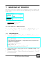
This chapter provides driver installation and un-installation procedures for Windows NT
3.51/4.x:. There is one driver directories under the \WINNT directory of the driver diskette,
for NT 3.51/4.x:
\WINNT\3_51-4_x
Trm3X5.sys:
(*)
Oemsetup.inf:
Device driver for NT 3.51
& 4.x
Device information file
Trm3X5.inf
Device information file
And two others are under the root directory:
•
•
7.1
TXTSETUP.OEM (Text Setup File)
DCSCI (Text Setup Tag File)
New Windows NT Installation
You can boot Microsoft Windows NT from Setup Diskette or CD-ROM. The following is the
procedure for installing the Tekram adapter driver while installing Windows NT.
7.1.1 Boot from Diskette:
1.
Insert the Microsoft Windows NT Setup Diskette for CD-ROM installation into drive A:
and boot from this disk.
Note: If you do not have the Windows NT Setup diskettes, you can create them from the
Windows NT CD-ROM:
a) First, prepare three blank formatted 3.5" floppy diskettes. Boot your system in DOS.
b) Change to the CD-ROM drive.
c) Then change to the i386 directory.
d) Type: WINNT /OX
This will generate three setup diskettes for Windows NT.
2.
The first screen of the NT setup program will show: “Welcome to Setup..." Press
"ENTER" to continue.
3.
The next screen will show: "Windows NT provides two Setup methods ....." Press "C"
to run the custom setup.
DC-395 Series User’s Manual
43
7. WINDOWS NT DRIVERS
4.
Press "S" to skip mass storage device detection. The next screen will show: “Setup has
recognized the following SCSI Adapters in your computer: (none).” Choose to configure
an additional SCSI adapter by pressing "S", and continue with the following steps:
5.
On the next screen, NT will show various drivers. Choose: "Other (Required disk
provided by a hardware manufacturer)" and press “ENTER”.
6.
NT will prompt for the "Manufacturer-supplied support disk". Insert the DC-395 driver
diskette in drive "A" and press “ENTER”.
7.
NT will check the floppy and show:
"Tekram DC-395U/UW/F or DC-315/U NT 3.51 & 4.x PCI SCSI Driver Ver. XXX"
Select the NT version you want to install and press "ENTER".
8.
After NT scans the hardware and finds the controller, it will display:
“Setup has recognized the following Mass Storage device in your computer:"
"Tekram DC-395U/UW or Dc-315?U PCI SCSI Adapter Ver. XXX"
Press “ENTER” to continue and copy the driver files. At this point, simply follow the
Microsoft Windows NT installation procedure.
7.1.2 Boot from CD-ROM :
You can boot from CD-ROM when you set the CD-ROM as a boot device from Main Board
BIOS for ATAPI CD-ROM or DC-395U/UW boot up screen for SCSI CD-ROM.
1.
Press "F6" key when the screen shows" Setup is inspecting your Computer's hardware
Configuration".
2.
The next screen will show: "Setup could not determine the type of one or more mass
storage device installed in your system ...". Choose to configure and specify additional
SCSI adapter by pressing "S".
3.
On the next screen, NT will show various drivers. Choose: "Other (Required disk
provided by a hardware manufacturer)" and press "ENTER".
4.
NT will prompt for the "Manufacturer-supplied hardware support disk" into drive A:
Insert the DC-395 driver diskette in drive "A" and press "ENTER".
5.
NT will check the floppy and show:
"Tekram DC-395U/UW/F or DC-315/U NT 3.51 & 4.x PCI SCSI Driver Ver. XXX"
and press "ENTER".
44
DC-395 Series User’s Manual
7. WINDOWS NT DRIVERS
6.
After NT scans the hardware and finds the controller, it will display:
"Setup has recognized the following Mass Storage devices in your computer:"
"Tekram DC-395U/UW/F or DC-315/U PCI SCSI Adapter Ver. XXX"
7.
Press "ENTER" to continue and copy the driver files. At this point, simply follow the
Microsoft Windows NT installation procedure.
7.2
Adding the Driver to an Existing NT System
7.2.1 For NT Versions 3.5x
1. Boot NT.
1.
From the Main Program group, double click the Windows NT Setup icon.
2.
From the "Option" pull-down menu, select "Add/Remove SCSI Adapters".
3.
Click the "Add" button and select "Other (Requires a disk form a hardware
manufacturer)".
4.
NT will prompt you to insert the "Manufacturer-supplied support disk". Insert the DC395 driver diskette into drive A: and type in the path:
A:\WINNT\3_51-4_x (For NT versions 3.51 and 4.0)
5.
Windows NT will show: "Tekram DC-395U/UW/F or DC_315/U PCI SCSI Adapter
Ver. XXX". Select "OK"
6.
Windows NT will display "Adapter: Tekram DC-395 PCI SCSI Adapter Ver. XXX"
Select "Install".
At this point, if the specified driver has already been installed, NT will display "The
drivers for this adapter are already on the system" Select "Current" if you want to use
existing driver, or select "New" if you want to replace or upgrade the current driver.
7.
Select "OK" to return to the Windows NT Setup program.
8.
Shut Down and restart the system.
DC-395 Series User’s Manual
45
7. WINDOWS NT DRIVERS
7.2.2 For NT Versions 4.x
1.
Boot NT.
2.
In Control Panel, double click the "SCSI Adapters" icon.
3.
4.
5.
Click on the "Drivers" Tab.
Click the "ADD" button.
Select "Have Disk".
6.
Insert the DC-395 Driver Disk in drive A: and type in the path: \WINNT\3_51-4_x
7.
Windows NT will show: "Tekram DC-395U/UW/F or DC-315/U PCI SCSI Adapter
Ver. XXX". Select "OK"
At this point, if the specified driver has already been installed, NT will display the
following message: “The drivers for this adapter are already on the system"
Select "Current" if you want to use existing driver, or select "New" if you want to
replace or upgrade the current driver then enter in the path to the driver files:
A:\WINNT\3_51-4_x
Restart the system.
8.
7.3
Removing the SCSI Host Adapter from the System
7.3.1 For NT Versions 3.5x
1.
2.
3.
4.
From the Main Program group, double click the Windows NT Setup icon.
From the "Option" pull-down menu, select "Add/Remove SCSI Adapters".
Select the specific SCSI adapter you want to remove.
Click the Remove button to delete the adapter.
7.3.2 For NT Versions 4.x
1.
2.
3.
4.
In Control Panel, double click the "SCSI Adapters" Icon.
Click on the "Drivers" Tab.
Select the driver you wish to remove and click "Remove".------------Select Yes to remove the driver.
46
DC-395 Series User’s Manual
8. WINDOWS 95/98 DRIVERS
This chapter provides installation procedures for the DC-395 series Windows 95/98 drivers.
Windows 95/98 must first be installed before beginning this procedure.
There are three driver files under the \WIN95_98 directory on the driver diskette:
•
TRM3X5.MPD: Windows 95/98 driver file
•
TRM3X5.INF: Information file
•
Readme.W98: Win98 readme file
8.1
New Windows 95/98 Installation
8.1.1 New Windows 95
This procedure installs the TRM3X5.MPD driver onto a Windows 95 system for all new
system installations. Use this procedure when initially upgrading to Windows 95. Windows
95 automatically adds the driver to the registry and copies the driver to the appropriate
directories.
1.
Start the Windows 95 Setup according to the Microsoft instructions.
2.
Open the Control Panel and double-click the System Icon.
3.
Click the “Device Manager” Tab and double-click "Other Devices".
4.
Select the "PCI SCSI Bus Controller" entry. Click the "Properties" button.
5.
Click the “Driver” Tab and choose "Change Driver".
6.
A"Select Hardware Type" dialog box appears. Double-click
7.
Click "Have Disk" and Insert the Tekram Driver diskette in drive A.
8.
Specify the path as A:\Win95_98. Click "OK".
9.
A"Select Device" dialog box shows "Tekram DC-395U/UW/F or DC-315/U PCI SCSI
Adapter". Click "OK".
'SCSI Controllers"
10. A" PCI SCSI Bus Controller Properties" dialog box shows driver Files directory
:\Windows\SYSTEM\IOSBUSYS\Trm3X5.mpd" , and click "OK"
11. A "System Settings Change" dialog box appears. Remove the driver disk from the drive
and click on the “Yes” choice to restart the computer.
DC-395 Series User’s Manual
47
8. WINDOWS 95/98 DRIVERS
8.1.2 New Windows 95 OSR2
The driver installation procedures are slightly different for the new Windows 95 “B” (OSR2).
The Windows 95 version is indicated under Control Panel – System.
1.
Start the Windows 95/98 Setup according to the Microsoft instructions.
2.
Open the Control Panel, and Double-click on the System icon.
3.
Click on the "Device Manager" tab and double-click "Other Devices' button.
4.
Select the "PCI Bus Controller" entry. Click the "Properties" button.
5.
Click the "Driver" Tab. Choose "Update Driver" button
6.
"Update Device Driver Wizard" starts and provides several windows with choice,
Follow the steps below to correctly install the device driver for windows 95.
7.
After the Introduction window appears, Select "Yes (Recommended) ..".
8.
Click "Next" and Insert the Tekram Driver diskette in drive A.
9.
Click "Other Locations" and specify the path as A:\Win95_98
10. Update Device Driver Wizard dialog box shows "Windows found the following update
driver for the device : Tekram DC-395U/UW/F or DC-315/U PCI SCSI Adapter. Click
"Finish".
11. A" Copying Files screen" dialog box appears, Specify path as A:\Win95_98 and click
"OK".
12. A "System Settings Change" dialog box appears. Remove the driver disk from the drive
and click on the "Yes" choice to restart the computer.
8.1.3 New Windows 98
Windows 98 will detect the DC-395 series PCI SCSI Adapter as an AMD or Symbios PCI
SCSI Controller and install its built-in driver during Windows 98 Setup. To replace the driver
with the Tekram driver, follow these steps:
1.
Start the Windows 98 Setup according to the Microsoft instructions.
2.
Open the Control Panel and double-click the System Icon.
3.
Click the "Device Manager" Tab.
4.
Select "PCI SCSI Bus Controller" entry and click "Properties".
5.
Click the "Driver" Tab and choose "Update Driver".
48
DC-395 Series User’s Manual
8. WINDOWS 95/98 DRIVERS
6.
"Update Device Driver Wizard" starts and provides several windows with choices.
Follow the steps below to correctly install the device driver for Windows 98.
7.
After the Introduction window appears, click on the "Next" button.
8.
The Wizard provides a choice between having the Wizard search for a better driver than
the one in use or displaying a list of drivers from a specific location. Choose "search
..." and click on the "Next" button.
9.
The next window allows the user to specify which device(s) will be searched, and
specify path as A:\WIN95-98 and click on the "Next" button.
10. The summary window displays the driver of choice and the path to be installed from is
brought up. Click on the "Next" button.
11. The Wizard summary window appears. Click on the "Finish" button.
12. A "System Settings Change" dialog box appears. Remove the driver disk from the drive
and click on the "Yes" choice to restart the computer.
8.2
Adding the Driver to an Existing 95/98 System
8.2.1 Existing 95 System Installation
1.
Boot Windows 95.
2.
Click Start. Move to Settings, Control Panel, and click.
3.
Double-click on the System icon.
4.
Click on the "Device Manager" tab.
5.
Double-click on the "SCSI controllers" entry.
6.
Select the "Tekram DC-395U/UW/F or DC-315/U PCI SCSI Host Adapter" entry. Click
the "Properties" button.
7.
Click the "Driver" tab.
8.
Click the "Change Driver" button.
9.
Click "Have Disk" and Insert the Tekram Driver diskette in drive A.
10. Specify the path as A:\Win95_98. Click "OK".
11. A" Select Device" dialog box shows "Tekram DC-395U/UW/F or DC-315/U PCI SCSI
Adapter”. Click "OK”.
DC-395 Series User’s Manual
49
8. WINDOWS 95/98 DRIVERS
12.
A" Tekram DC-395U/UW/F or DC-315/U PCI SCSI Host Adapter" shows driver Files
directory :\Windows\SYSTEM\IOSBUSYS\Trm3X5.mpd", and click "OK".
13. A "System Settings Change" dialog box appears. Remove the driver disk from the drive
and click on the “Yes” choice to restart the computer.
8.2.2 Existing 95 OSR2 System Installation
1.
Boot Windows 95.
2.
Click Start. Move to Settings, Control Panel, and click.
3.
Double-click on the System icon.
4.
Click on the "Device Manager" tab.
5.
Double-click on the "SCSI controllers" entry.
6.
Select the "Tekram DC-395U/UW/F or DC-315/U PCI SCSI Host Adapter" entry. Click
the "Properties" button.
7.
Click the "Driver" tab.
8.
Click the "Update Driver" button.
9.
"Update Device Driver Wizard" starts and provides several windows with choice,
Follow the steps below to correctly install the device driver for Windows 95.
10. After the Introduction window appears, Select "Yes (Recommended).."
11. Click "Next" and Insert the Tekram Driver diskette in drive A.
12. Click "Other Locations" and specify the path as A:\Win95_98
13. Update Device Driver Wizard dialog box shows "Windows found The following
update driver for the device : Tekram DC-395U/UW/F or DC-315/U PCI SCSI Adapter.
Click "Finish".
14. A" Copying Files screen" dialog box appears, Specify path as A:\Win95_98 and click
"OK"
15. A "System Settings Change" dialog box appears. Remove the driver disk from the drive
and click on the “Yes” choice to restart the computer.
50
DC-395 Series User’s Manual
8. WINDOWS 95/98 DRIVERS
8.2.3 For Existing 98 system installation
1.
Start the Windows 98 Setup according to the Microsoft instructions.
2.
Open the Control Panel and double-click the System Icon.
3.
Click the "Device Manager" Tab, and Double click on the "SCSI controllers".
4.
Select "Tekram DC-395U/UW/F or DC-315/U PCI SCSI Adapter" entry and click
"Properties".
5.
Click the "Driver" Tab and choose "Update Driver". "Update Device Driver Wizard"
starts and provides several windows with choices. Follow the steps below to correctly
install the device driver for Windows 98.
6.
After the Introduction window appears, click on the "Next" button.
7.
The Wizard provides a choice between having the Wizard search for a better driver than
the one in use or displaying a list of drivers from a specific location. Choose
"search..." and click on the "Next" button.
8.
The next window allows the user to specify which device(s) will be searched, and
Specify path as A:\WIN95_98.
9.
The next window advises that you continue using the currently installed driver. Mark
"Install one of the other drivers" and click on the "View List" button.
10. The next window displays a list of drivers from the specified search devices and the
currently installed driver. Highlight the driver of choice and click "OK".
11. The previous window appears with the selected driver displayed as the driver to install.
Click on the "Next" button.
12. The summary window displays the driver of choice and the path to be installed from is
brought up. Click on the "Next" button.
13. The Wizard summary window appears. Click on the "Finish" button.
14. A "System Settings Change" dialog box appears. Remove the Driver disk from the
drive and click on the "Yes" choice to restart the computer.
DC-395 Series User’s Manual
51
9. SCO UNIX DRIVERS
This chapter explains how to install the SCO Unix/OpenServer Boot Time Loadable Driver
(BTLD) for Tekram PCI SCSI adapter DC-395.
Two different installation procedures will be described separately. Use the one that fits your
environment:
•
•
SCO Uuix/OpenServer has been installed on a non-SCSI boot drive
SCO Unix/OpenServer is to be installed from scratch on a SCSI drive attached to a DC395 host adapter
The example used throughout this chapter is for DC-395 under SCO Unix 3.2v4.x. The
following is the table for mapping different driver names used for DC-395 series under either
SCO Unix 3.2v4.x or SCO OpenServer 5.0:
SCO Unix 3.2v4.x
SCO OpenServer 5.0.X
9.1
DC-395U/UW/F
t3x5
t3x5
New SCO UNIX Installation
with DC-395 as the primary SCSI adapter
9.1.1 How to prepare a driver diskette
SCO395.ZIP is a compressed file of the SCO Unix/ OpenServer driver diskette. In order to
install the Unix/ OpenServer driver, a 1.44M diskette must be made first from this file.
Follow the steps below:
1.
2.
Unzip the Open SCO Unix/OpenServer Driver WINZIP File to get the disk image file.
Use the utility RAWRITE.EXE to generate a driver's floppy diskette.
File Name:SCO395.ZIP includes two files:
(1) RAWRITE EXE
(2) OS5_395
C:\unzipped\SCO>RAWRITE OS5_395 ------> Enter
RaWrite 1.2 - Write disk file to raw floppy diskette
52
DC-395 Series User’s Manual
9. SCO UNIX DRIVERS
Enter source file name: OS5_395 ------> Enter
Enter destination drive: A: ------> Enter
Please insert a formatted diskette into drive A: and press -ENTER- :
Number of sectors per track for this disk is 18
Writing image to drive A:. Press ^C to avort.
Track: 79 Head: 1 Sector: 16
Done.
The SCO Unix/OpenServer driver diskette is now made.
Please refer to the following instruction for installation procedures._
1.
Insert the system diskette N1 and boot up.
2.
When the boot prompt is shown:
Boot :
Type the following command to proceed:
link
3.
What package do you need linked in the system, or a to quit?
Type the following package name to proceed:
t3x5
The system will keep booting from floppy N1, then request to have the driver diskette
inserted. Insert the SCO driver disk. After the driver is successfully loaded, follow the normal
procedures to install SCO Unix/OpenServer. During the installation process, the driver
diskette may need to be inserted again as instructed.
Once the system reboots with the driver successfully installed, messages similar to the
following will be displayed:
device
address
vector dma comment
——————————————————————————————————
%DC3X5
Tekram PCI SCSI adapter driver(V3.00)
%+adapter
0x9000-0x9100 11
ha=0/id=7 at bus=0/dev=5/func=0
%++device
id=0/lun=0/disk/206MB/”IBM ...”
%++device
id=2/lun=0/tape/”WANGTEK ...”
DC-395 Series User’s Manual
53
9. SCO UNIX DRIVERS
9.2
Adding the Driver to an Existing SCO UNIX System
with non-SCSI boot drive
1.
2.
Boot SCO UNIX into administration (single user) mode.
It is required to make a backup copy of the working UNIX kernel in case a hazardous
condition should arise. Use the following command to make the copy diskette first:
cp /unix /unix.ok
3.
Insert the BTLD driver diskette into the floppy drive and start the installation by typing:
installpkg
4.
The screen will then show the driver package description:
NAME
5.
DESCRIPTION
t3x5
Tekram DC3XX series PCI SCSI Host Adapter (VX.X)
Type the following command to install the driver:
t3x5
If system prompts to replace original driver,press <return> to confirm.
6.
A series of messages will be displayed. The procedure is completed.
7.
If any SCSI device is to be added (it is NOT necessary to have the hardware actually
connected !!), now is the time to do it. Refer to the SCO Unix/OpenServer
administrator’s manual for how to add SCSI devices to the system.
Note: It is important that when you are asked to input the driver prefix, enter tps in
response, and proceed as normal. Or, you can manually edit the SCSI device
configuration file /etc/conf/cf.d/mscsi.
8.
After the devices are added, rebuild the kernel as instructed. If you do not plan to add
any devices, in order to rebuild the kernel, type the following commands:
cd /etc/conf/cf.d
./link_unix
9.
Reboot the system for the changes to take effect.
54
DC-395 Series User’s Manual
APPENDIX
A. Specifications
PCI Features
•
•
•
•
•
PCI Specification Revision 2.1 compliant with full PnP support by host adapter's BIOS
High speed 32-bit PCI bus master DMA transfers of up to 132 Mbyte/sec in burst mode
Direct glueless interface to 33MHz, 32-bit PCI bus
Support for Scatter-Gather DMA data transfers
Multiple-byte DMA FIFO for low bus latency
SCSI Features
SCSI Protocol
Model No.
Max. sync.
data Xfer rate
SCSI-I
SCSI-II SCSI-3
4
4
4
DC-395U
20
4
4
4
DC-395UW/F
40
•
Boot ROM support
•
On-chip state machine to control the SCSI sequences in hardware
•
Target Command Set Support
•
Single-Ended 48mA outputs to drive the SCSI bus directly
Max.
Devices
7
15
Overall Features
•
•
•
•
•
•
Supports Flash BIOS
Level Triggering support allows multiple adapters to share a single interrupt
Coexists with other SCSI, ESDI, or IDE adapters
Supports up to eight drives in DOS 5.0/6.x without the need for device drivers
Complete software driver support for all major PC operating systems
User friendly utility for quick and easy adapter installation and system configuration.
DC-395 Series User’s Manual
55
B. Product Support Form
The following information may be required by your supplier in order to obtain technical
support assistance:
1. Have you tried the General Troubleshooting Tips in Appendix C without success?
Yes? ____ No? ____
2.
DC-395 Information
- Serial #
:
- Purchase Date
:
- Firmware Version :
- BIOS Version
:
- Driver Installed :
________________________
________________________
________________________
________________________
________________________
3.
System Hardware Configuration (please list the manufacturer/model/chip and SCSI ID
of each device)
- Motherboard Speed : _____________________
- MB DRAM/SRAM : _____________________
- Video card : _____________________
- Hard disk/Floppy card 1 : _____________________
2 : _____________________
- Network card : _____________________
- Hard disk drive(s) : 1 : _____________________
(SCSI)
2 : _____________________
3 : _____________________
4 : _____________________
- Floppy drive(s) : 1 : _____________________
2 : _____________________
- Other devices : 1:_____________________
(IDE/ESDI) 2:_____________________
3:_____________________
4: _____________________
- Other SCSI device(s): 1: _____________________
2: _____________________
3: _____________________
4: _____________________
4.
System Software Configuration (please list the version)
- Operating System
: _____________________
- Application Program : _____________________
5. Detailed description of error messages and symptoms with information on CONFIG.SYS,
AUTOEXEC.BAT, and PCU options
56
DC-395 Series User’s Manual
C. General Troubleshooting Tips
Most controller errors are traceable to external factors, such as conflicts with other installed
cards, bad or incorrectly configured drives, loose cables, improper SCSI termination, or other
installation errors. To troubleshoot SCSI problems, try simplifying your hardware
configuration by removing some devices from the system and then adding them back one at a
time. For slow external SCSI devices you may also try to set the “Sync Negotiation” to “No”,
i.e., Async, or decrease the transfer rate to a lower speed within DC-395’s PCU.
Look for the latest information on Tekram SCSI Controllers as well as the newest drivers on
the Tekram web site at http://www.tekram.com or ftp://ftp.tekram.com. The following are
general guidelines for some specific error conditions:
1. The error: "WARNING: 64Heads, 32 Sectors Parameter is expected...." pops
up after the DC-395 BIOS:
•
The most likely cause of this error message is using the DC-395 with a drive that has
been formatted with a different controller. Try toggling the setting: Greater Than 1G
Support in the PCU.
•
If the above solution does not work, you must boot from a floppy and run FDISK.EXE
to delete the partitions. Then, re-Fdisk and Format the drive to make it compatible with
the DC-395.
2. The BIOS Message of the DC-395 never appears on the screen:
•
Check if you have any other cards in the system that could be using BIOS addresses
C800 - DC00. If you do, one of these cards may be conflicting with the BIOS of the DC395. Take out the suspect cards and see if the BIOS for the DC-395 comes up. If it does,
change the address on the conflicting card.
3. The <<< Press F2 or F6 …>>> BIOS Message is missing after BIOS upgrade:
•
After BIOS upgrade there will be no <<<Press F2 …>>> message shown along with
DC-395’s BIOS message during next bootup, since the setting for “F2 or F6 Function
During Bootup” is set to “Disabled”. To enable this display you need to execute
\DOS\UTIL.EXE from the DOS/NetWare driver diskette and set the “F2 or F6 Function
During Bootup” in “Set Adapter Options” to “Enabled”.
4. When the system attempts to boot, the error: "Missing Operating System"
pops up:
•
If you are using a drive that has been formatted with a different controller, try changing
the Greater Than 1G Support option in the DC-395 BIOS. If you still get the error, you
must re-Fdisk and Format the drive to get it to boot normally.
DC-395 Series User’s Manual
57
C. General Troubleshooting Tips
5. A connected device is not recognized by the DC-395:
•
If the device is a hard drive, particularly an older one, there may not be a sufficient delay
time specified in the DC-395 PCU. You can tell if this is the case by simply warm
booting the computer after the drive has had plenty of time to spin up. If the controller
sees the drive then, go into the DC-395 BIOS and increase the setting: Delay Before
BIOS Scans Device.
•
Make sure the option “Included in BIOS Scan” is set to “Yes” for that device ID.
•
If the device is not a hard drive or the above solution does not work, first check to see if
any device is recognized. Try devices one at a time to make sure the cable or card is not
bad. If there is one device that will not be seen, check the SCSI ID and terminators. The
SCSI ID should not be on 7. If a SCSI device is not seen by the card, keep in mind that it
is very unlikely a fault with the card itself. The card should identify any properly
connected SCSI device.
6. Possible incompatibility problems when enabling the More Than 2 Drives
Support option in the PCU:
•
Due to the condition of occupying the 1KB (639KB-640KB) of memory space, some
software, such as anti-virus programs may issue false alarms.
7. System Hangs very soon after the PCU setup:
•
For some specific drives, such as the NEC 384, Seagate ST3283N, & Alps DR312D, set
the Max Sync Xfer Rate option to 5MB/sec instead of 10MB/sec (default).
8. The Message: "No BIOS Disk Found! SCSI BIOS Not Installed!" is displayed by the
DC-395 BIOS:
•
This message is normal when only a CD-ROM device is installed. Since this type of
device uses device drivers, the DC-395's BIOS is not installed.
9. "No Valid SCSI Device Found!" is displayed during boot-up:
•
If this message is generated by the driver TRMDISK.SYS, you probably do not need it
in CONFIG.SYS. Remember, this driver is only for Removable Devices (and HDs if
More Than 2 Drives Support is Disabled).
10. SCSI device is not presented in the DC-395’s BIOS message during bootup:
•
Check that the Included In BIOS Scan option in “Set Device Options” is set to Yes or
not. Setting this option to Yes will enable the DC-395’s BIOS to re-scan this device
during the next bootup.
58
DC-395 Series User’s Manual
D. Flash BIOS Programming Utility
Flash BIOS is featured on DC-395 series with the exception of DC-395 (The word
“FLASH” on the adapter’s BIOS chip indicates flash support).
Updating the DC-395U/UW/F BIOS Code is made easy with the TRMFLASH.EXE Utility,
which can be found in the <BIOS> directory of the driver disk. Since the DC-395U/UW
feature FLASH BIOS, it is not necessary to change the actual BIOS chip in order to upgrade
the SCSI BIOS. The user can simply re-program the old BIOS using the TRMFLASH.EXE
Utility as follows:
1.
First, boot the system with DOS or to “Safe Mode” under Windows 95. If you are
booting DOS from a hard drive or floppy disk, press [F5] when the message “Starting
MS-DOS…” appears on the screen. If you are booting Windows 95, press the [F8] key,
and select the “Safe mode command prompt” option. This will assure that the system is
running in “real mode” with no device drivers loaded. This is the only correct way to
run the TRMFLASH Utility program.
2.
There are (2) important files needed to re-program the BIOS. The first is
“TRMFLASH.EXE” which is the FLASH BIOS Programming Utility. The second file
needed is the updated “BIN” file which contains the actual BIOS code. This file will
have the extension [.bin], such as “Trm3x5.bin”. Make sure these files are on the
diskette or hard drive in the same directory.
3.
Starts the TRMFLASH Utility by changing to the directory where the two required files
exist and typing: TRMFLASH and pressing [ENTER].
4.
The TRMFLASH Utility Screen appears. You will be asked for the file name to
program. Type in the name of the new BIOS (.bin) file and hit [ENTER].
5.
The program will then ask if you want to backup the old BIOS. This is recommended in
case there are any problems with the new “.bin” file. Enter the name of the new backup
file (such as “backup.bin”) and press [ENTER].
6.
At this time the system will prompt you for final confirmation before beginning
programming. The Utility can be aborted at this time by hitting “n”. To begin
programming, hit “y”…
When the Flash programming starts, a bar indicator will show the progress of the
programming operation. After successful completion, hit the reset button or power off the
computer.
After BIOS upgrade, there will be no <<<Press F2 …>>> message shown along with DC395’s BIOS message during next bootup. To enable this display you need to execute
\DOS\UTIL.EXE from the DOS/NetWare driver diskette and set the “F2 or F6 Function
During Bootup” in “Set Adapter Options” to “Enabled”.
DC-395 Series User’s Manual
59