1
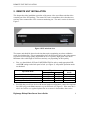
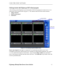
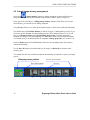
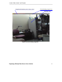
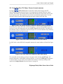
Dial Up Video Server
Model: DGRT400
Installation / User Manual
Table of Contents
1.
GENERAL INFORMATION.......................................................................................... 5
1.1
1.2
1.3
INTRODUCTION................................................................................................................ 5
TECHNICAL SPECIFICATION............................................................................................. 7
SYSTEM REQUIREMENTS ................................................................................................. 7
2.
REMOTE UNIT INSTALLATION................................................................................ 9
3.
SOFTWARE INSTALLATION.................................................................................... 12
4.
UNINSTALLATION...................................................................................................... 13
5.
USING THE CLIENT SOFTWARE ............................................................................ 14
GETTING STARTED WITH DIGIMERGE DVS CLIENT PROGRAM ................................................ 15
5.1.1
Main control panel ................................................................................................ 16
5.1.2
Getting initial images from DVS............................................................................ 17
5.1.3
Image window description ..................................................................................... 20
5.2 CONFIGURING THE REMOTE DVS UNIT......................................................................... 22
5.2.1
Modifying basic and image parameters................................................................. 22
5.2.2
Setting up Callback parameters............................................................................. 24
5.2.3
Changing external modem parameters.................................................................. 28
5.3 MOTION DETECTION CONTROL .................................................................................... 30
5.4 RELAYS AND SENSORS CONTROL .................................................................................. 31
5.5 INTERNAL IMAGE MEMORY MANAGEMENT................................................................... 32
5.6 CONTROLLING PAN, TILT, ZOOM, FOCUS OF REMOTE CAMERAS ................................. 34
5.7 AUDIO STREAM CONTROL ............................................................................................. 36
5.8 COMPACTFLASH MANAGEMENT ................................................................................... 38
5.9 PREPARING AND USING CALLBACK MODE WITH MOTION AND SENSORS ALARM
DETECTION ............................................................................................................................... 41
5.10
DVS PROGRAM COMMANDS IN DETAIL ..................................................................... 44
5.10.1 Additional dialing options ..................................................................................... 44
5.10.2 Changing and memorizing the DVS password ...................................................... 47
5.10.3 Retrieving software and firmware versions ........................................................... 49
6.
DVS OPERATION MODES.......................................................................................... 50
6.1
6.2
6.3
INTERNAL MODEM MODE .............................................................................................. 50
DIRECT CABLE CONNECTION (COM PORT) MODE ........................................................ 50
CUSTOM CONFIGURATION (EXTERNAL MODEM) MODE ................................................ 52
Digimerge Dialup Video Server User’s Guide
3
7.
TROUBLESHOOTING ................................................................................................. 53
7.1
8.
4
HOW TO GET SOFTWARE UPDATES AND TECHNICAL SUPPORT ...................................... 53
WARRANTY PAGE………………………………………..………………….………55
Digimerge Dialup Video Server User’s Guide
GENERAL INFORMATION
1. GENERAL INFORMATION
1.1 Introduction
Thank you for purchasing Digimerge product. The Dialup Video Server (DVS) will enable you
to monitor sensitive locations and remote areas over standard phone lines. A key feature of
DVS is the ability to not only visually survey a sensitive location, but to also hear what is
occurring at the scene as well as speak to anyone at the monitored location. A standalone DVS
unit installed on-site with video and audio feed from up to four cameras and connected to a
phone line lets you see and hear exactly what is happening and verbally interact with the
individuals at the sight.
No special hardware is required at the operator's PC, just a modem. Images are transmitted by
the remote DVS unit will be decoded by a special client software and displayed on the screen or
stored onto a hard disk for later examination. The operator, who can be located several
thousand miles away, is in complete control of the DVS and any cameras attached to it. This
allows for incredible expandability and flexibility of the security and surveillance network.
Important features of DVS-based surveillance system include:
• DVS is low cost, maintenance-free standalone unit.
• High quality Wavelet-compressed video from 4 sources and one channel full duplex
audio can be transmitted simultaneously between DVS and supervisor’s PC through an
ordinary phone line (POT line) using internal PSTN modem at a bit rate up to 56Kbps.
• Optional connection types supported: External PSTN modem, ISDN modem, cellular
services (GSM, CDMA modem), dedicated line modems and direct cable connections.
• DVS unit and PC client software are specifically designed for extremely low speed
connections, giving the user surveillance capability approaching real-time. Maximum
achievable video update rate for one camera source with a 28.8 kbps modem connection
at a resolution of 170x120 is 5 frames per second.
• Snapshots – high quality/resolution images can be captured into internal DVS memory
at operator’s request, while monitoring an area with low quality/resolution but high frame
rate.
• Audio user interface provides full control in audio streaming mode.
• Non-volatile internal video memory plus CompactFlash (removable) are used as video
storage.
• Callback mode: DVS unit can be instructed to call a PC back and notify you about
suspicious activity in the monitored area or alarm events on sensor’s inputs, and show
high quality captured snapshots sequence (user defined) on the screen which can be
automatically saved as a JPG or AVI file without any user interaction.
• Motion Detection is provided with adjustable sensitivity levels and camera
participation in a motion monitoring cycle for every camera.
• Password protection is available to prevent unauthorized access.
• Internal timer for pictures time stamp.
Digimerge Dialup Video Server User’s Guide
5
GENERAL INFORMATION
• Camera Pan/Tilt/Zoom (PTZ) control for certain camera models: SONY EVI-G20,
SONY EVI-D30, KALATEL, PHILIPS TC-700 and DCP-1010 (Pelco-D) etc.
• Can be optionally connected to Windows-based WWW server to make JPEG images
available through the web browser.
DVS will become an important part of your personal or corporate security video and audio
surveillance system.
6
Digimerge Dialup Video Server User’s Guide
GENERAL INFORMATION
1.2 Technical specification
•
•
•
•
•
•
•
•
•
•
•
•
•
•
4 BNC composite video inputs (1 Vp-p/75 Ohm)
One full duplex audio channel: Microphone/Linear and Speaker jack’s connectors
provided for external electret-foil microphone and speaker.
2 RS-232 ports (male). One RS-232 is for external modem and another for PTZ
function support.
8 inputs (TTL level) for external alarm sensors.
4 relay outputs (0 - 400V AC/DC, 120 ma) that can operate on alarm events: sensors
toggling, motion detection, video loss.
Onboard memory: 512 KB for compressed video buffering (non-volatile). Approximate
storage capacity: 50 snapshots of good quality at 340x240 resolution.
CompactFlash socket – memory card can be used as an optional expanded removable
storage.
Video Input Type: NTSC, PAL, B/W 60 Hz, B/W 50 Hz.
Video Resolution: 680x480, 340x240, 170x120.
Video Compression: Wavelet.
Audio Compression: G723.1 5.3 Kbps.
Dimensions: 310mm x 140 mm x 56 mm. (12.20" x 5.51" x 2.20")
Power consumption: +12V/0.5A (requires external power supply 1.2A recommended).
Operating temperature: 0°C ~ +50°C (system is designed for in-door use)
1.3 System requirements
The following are minimum system requirements for an operator’s PC sufficient to run
Digimerge DVS client software:
•
•
•
•
Desktop or notebook PC with Intel Pentium™ 90 MHz or compatible CPU.
Pentium II™ MMX™ 300 or better CPU is recommended for optimal system
performance.
32 MB of system RAM (64MB for Windows NT).
More memory is recommended for improved overall system performance.
Microsoft® Windows® 95, Windows® 98, Windows NT™ 4.0, Windows® 2000,
Windows® XP.
Any Windows-compatible modem (internal or external). 57.6 Kbps modem is
recommended.
Digimerge Dialup Video Server User’s Guide
7
GENERAL INFORMATION
•
•
Display adapter configured for 16-bit or better color mode (32768 or more colors)
at 800x600 or higher resolution.
5 MB of free space on system hard disk are required for standard software installation.
Additional free space is required to store individual still images and image sequences.
The rest of this document contains important installation and operating instructions for DVS
hardware (remote unit) and the client software on the operator’s PC. Be sure to read all
applicable sections carefully before proceeding.
8
Digimerge Dialup Video Server User’s Guide
REMOTE UNIT INSTALLATION
2. REMOTE UNIT INSTALLATION
This chapter describes installation procedure of the remote video surveillance unit that is the
essential part of the DVS package. The remote DVS unit is a standalone device that does not
need any direct connection to a PC on remote monitoring site. The unit’s exterior is shown in
Figure 1.
Figure 1 DVS unit front view
The remote unit should be placed on the site that requires monitoring, anywhere within the
reach of a telephone line. It is recommended to place the DVS unit as near to the video cameras
as possible to avoid image quality degradation or use of expensive high-grade video cables.
Maximum video cable length is 100 meters and may vary depending on cable quality.
•
First, you should check DVS unit CONFIGURATION in order to make appropriate DIPswitch SW settings on the back panel of unit (see Figure 2). All possible operation modes
are tabulated:
Operation Mode
Internal modem (standard)
Direct cable connection (COM-port)
Custom configuration (external modem)
Auxiliary (reserved)
•
SW position
Aux mode
ON
OFF
OFF
ON
OFF
OFF
ON
ON
Internal modem
Reference for
details
Section 6.1
Section 6.2
Section 6.3
-
Provided that you will use device with internal modem configuration, connect the telephone
line (RJ11 plug) to the Line connector on your DVS unit (see Figure 2). If the same line is
also to be used for as a regular telephone line or to connect a fax machine, then use the
Digimerge Dialup Video Server User’s Guide
9
REMOTE UNIT INSTALLATION
Phone connector on the DVS. In that case, you may need to adjust (increase) the number of
rings after which the DVS will respond to an incoming call in order to avoid conflicts with
normal phone and/or fax usage and the associated inconveniences. See section 5.2.1 and
Figure 7 on page 23 for more information on DVS configuration options.
Note:
•
•
The condition of the telephone line could be a reason for low modem connection
rate and poor image transmission performance. We recommend you to avoid
connecting DVS through PBX boxes because the reduced voltage may interfere
with connection reliability. We also suggest that you use a direct telephone line
connection to hook up the DVS unit. Finally, since the DVS system is designed for
in-door use, it should not be installed in places with high humidity or extreme
temperature variation.
Next, connect one or more video cameras to any of the 4 BNC connectors on the back panel
of the DVS box. DVS is capable of camera auto-detection so you are free to use any of the
unit’s video inputs in any order. You may also safely mix color and black & white cameras,
as long as they all conform to the same electrical and video standard (NTSC or PAL).
However, mixture not recommended because of possible video synchronization problems.
Then power on the cameras.
Finally, after all other connections are completed, connect the power supply cord (DC 12V
1.2A) to the corresponding socket on the DVS unit.
Immediately after the power is supplied to the DVS unit, the board starts the internal self-test.
Test progress is always shown on the front LEDs. There are 2 LEDs: POWER (yellow) and
ACTIVE (green). The LEDs will behave in the manner as described below during power up
sequence:
Test (power-up) behavior of DVS unit.
1. ACTIVE (green) and POWER (yellow) turn on together, then ACTIVE (green) turns
off.
2. POWER (yellow) during the whole test will indicate test progress step by step by
turning off for a short time at the beginning of each step 13 times.
3. When the test successfully passes, POWER (yellow) remains lit and the ACTIVE
(green) starts blinking 2 times per second (status is disconnected).
4. When the DVS detects a connection, the ACTIVE (green) light will blink at double the
rate it blinks in the disconnected state.
If these steps do not occur with your system, disconnect and reconnect the power and try again.
The detailed layout of DVS connectors are shown in Figure 2. It is very simple and well
inscribed.
10
Digimerge Dialup Video Server User’s Guide
REMOTE UNIT INSTALLATION
Figure 2 DVS unit rear view
If all connections are properly made and the DVS start up process is completed successfully,
proceed to the following chapters to learn how to install and use Digimerge DVS client software
from your PC.
Digimerge Dialup Video Server User’s Guide
11
SOFTWARE INSTALLATION
3. SOFTWARE INSTALLATION
The Digimerge DVS client software can be easily installed on any desktop or notebook PC
running Windows 95, Windows 98, Windows Me, Windows NT 4.0, Windows 2000 or
Windows XP operating systems that is equipped with an internal or external modem. The
installation is done by simply double-clicking on the dm51xx.exe self-installable file (xx here is
the version number). The install script will then proceed and you should follow the prompts as
indicated.
As a result, the Digimerge DVS application program (DM51App.exe) and the online help file
will be installed automatically on the PC. However, before you proceed with launching the
Digimerge DVS software for the very first time, make sure that the modem drivers and other
software are correctly installed and functional.
12
Digimerge Dialup Video Server User’s Guide
UNINSTALLATION
4. UNINSTALLATION
You can remove the Digimerge DVS client software from your computer at any time, if desired.
The complete product uninstallation can be accomplished by doing one of the following actions:
1. Start -> Programs->Digimerge -> Dialup Video Server -> Uninstall
2. Re-execute the installation program dm51xx.exe (xx here is the software version
number)
3. Launch the Windows Control Panel and then select the Add/Remove Programs icon.
Locate the Digimerge DVS line in the list of the installed software and double-click on
it.
After receiving a confirmation, the uninstaller will delete the Digimerge DVS application and
help files; destroy the corresponding software folder and remove all the registry keys, which
were created by the Digimerge DVS client software.
Note:
The uninstaller will not delete any data files (still images in .JPG format or image
sequences in .AVI format) created by Digimerge DVS software. Also, the
uninstallation of Digimerge DVS software will not affect modem drivers or its
settings in any way.
Digimerge Dialup Video Server User’s Guide
13
USING THE CLIENT SOFTWARE
5. USING THE CLIENT SOFTWARE
This chapter describes the Digimerge DVS client software, including all control elements related
to video images, cameras, alarm sensors and output relays. After successful completion of
software installation the main Digimerge DVS client program can be launched either from the
Digimerge Dialup Video Server program group or by clicking on the
DVS icon on the
Windows Desktop.
The following section will outline usage of the program and lead you through a process of
viewing your first images from a remotely installed DVS unit. Sections 5.2 through 5.10
provide advanced users information on commands, parameters and operation modes associated
with DVS software.
14
Digimerge Dialup Video Server User’s Guide
USING THE CLIENT SOFTWARE
Getting started with Digimerge DVS client program
After clicking on the Digimerge icon to launch the DVS client program, the main screen, in its
initial state will be shown below (Figure 3). The window consists of three main elements:
• Image windows
• Main control panel
• Status bar
Image window
Status bar
Control panel
Figure 3 DVS client program (initial state)
Main control panel at the right is comprised of several buttons that allow you to issue
commands to the remote DVS unit and view or modify its configuration parameters (see section
5.1.1 for detailed description of each button). The resizable Image windows are intended to
show video images acquired from the remote DVS unit. The Status bar is provided to show the
current operational status.
Digimerge Dialup Video Server User’s Guide
15
USING THE CLIENT SOFTWARE
5.1.1 Main control panel
The Digimerge DVS main control panel provides an easy way to perform any operation with a
remote unit. Each of the buttons are described in detail below.
Displays the Establishing connection dialog and lets you connect to any of the
available remote DVS units. Use the same button to break the connection.
When connected, the control button changes.
Properties button lets you view and modify configuration information stored in the
remote unit that you are currently connected to (refer section 5.2 for details).
Motion detection button displays motion detection control window (refer section 5.3
for details).
Sensor and relay button displays relays/sensors control window (refer section 5.4 for
details).
Image memory button activates the DVS internal image memory control window that
shows a preview of images stored on board (refer section 5.5 for details).
PTZ control button activates the PTZ control window (refer section 5.6 for details).
Audio control button activates the control window with all available audio functions
(refer section 5.7 for details).
CompactFlash memory button activates the DVS CompactFlash window that
maintains all operations with files (refer section 5.8 for details).
Snapshot size buttons:
(680x480),
(340x240),
(170x120) affect
the resolution of images, captured into the DVS internal image memory by mouse clicking on
the image window.
16
Digimerge Dialup Video Server User’s Guide
USING THE CLIENT SOFTWARE
5.1.2 Getting initial images from the DVS
Before you can get any images from the DVS unit, you need to establish a connection from your
PC. Press the
(Connect to remote unit) button on the main control panel. This will
bring up the Establishing connection dialog as shown in Figure 4. Use the Phone number
field to enter the telephone number assigned to the line connected on the remote DVS unit you
are trying to access. If the DVS unit is located in another city or country, be sure to include the
long distance or international dialing codes as well as the outside line access code, if any. The
DVS program will simplify access if you “check” the Using Country and Area Codes box
below.
Figure 4 Dialing up a remote unit
Digimerge Dialup Video Server User’s Guide
17
USING THE CLIENT SOFTWARE
Note that, as you enter any telephone number in the dialog, it will be memorized automatically,
so the next time you will not have to retype it again. Simply pull the list down by the small
arrow button on the right to choose from the 10 most recently used numbers. You can remove
unwanted telephone numbers from the list by pressing the Delete Phone Number button right
above it.
The password is required in order to prevent unauthorized access to the remote DVS unit. Enter
the correct password in the Remote Unit Login field. Note that for security reasons the entered
password will be masked by a number of asterisks (*).
Note:
The default password provided from Digimerge is set to qwert (in lower case).
It is highly recommended to change it as soon as possible in order to prevent
unauthorized use of the DVS unit. See section 5.10.2 for details on how to
change the password. After the password is changed, keep a record in a safe
place so you don’t forget it.
There are a few other selections and buttons available in the dialog. These are not essential to
remote connection. A detailed description of their use is found in section 5.10.1. Simply press
Connect after entering and verifying the number.
Now your modem will begin dialing the given telephone number and attempt to establish a
connection to the DVS unit on the other end of the line. It may take some time, perhaps up to a
minute, depending on the type of line and telephone number, before a reliable connection is
established. It is possible that you will have to try dialing several times if the line is busy or the
connection is slow or unreliable. To redial, press the
(Disconnect) and then
(Connect to remote unit) buttons on the main control panel again.
Selecting the COM Port button in the Establishing Connection dialog (shown in Figure 4)
performs a direct connection through the null-modem cable. The correct port number and
desired speed settings must be established. All modem controls are unavailable in this mode,
and thus disabled. To start the connection process you need to press Connect in the same
manner as in modem mode. Additional information on this topic can be found in section 6.2 on
page 50. When using a direct cable connection, be sure that configuration switches SW on the
back panel of DVS are set as shown in Figure 34 on page 51 before the last power up on the
DVS unit.
During the connection process, its current state will be displayed in the Status bar of the main
window. Connection failure may occur if you have the wrong password, busy line, etc. This will
help you monitor the programs current state.
18
Digimerge Dialup Video Server User’s Guide
USING THE CLIENT SOFTWARE
DVS unit will automatically begin transmission of the first images using the last stored or the
factory default settings. Loading progress bars at the top right corner of each image window will
show a green progress indicator that will advance as the image data is being received. For use
of camera auto detection, access the Image Properties dialog as described in section 5.2.1. The
process of loading images will normally take a few seconds for fast connections, medium image
resolution and quality settings. Finally, images from all of the connected cameras to the remote
DVS unit (up to four) should appear in the program window as shown in Figure 5.
Figure 5 Example image received from a DVS unit
You can easily change image resolution by pressing
or
buttons in Image Window.
The program window displays information about connection speed in bits per second (bps) in
the window Status bar.
You can also press the
(Properties) button to view or change the configuration of the
remote unit that you are connected to. The DVS configuration parameters are described in
detail, in section 5.2. Finally, you can terminate the connection by pressing the
(Disconnect) button.
Digimerge Dialup Video Server User’s Guide
19
USING THE CLIENT SOFTWARE
5.1.3 Image window description
Figure 6 shows all controls available from the image window.
Include in/exclude from
update image cycle
Camera name
Loading progress bar
Loading time (sec)
Alarm indicator
Save image as JPG
Save sequence as AVI
Image Area
Change window size
Resize corner
Image Brightness, Contrast, and Saturation settings
Image quality
Figure 6 Image window interface
Images from all cameras are updated in cyclic mode by default. You are also able to assign one
camera for faster update, by mouse clicking on the image window caption (single mode). Image
window frame will be highlighted in single mode. You may return to cyclic mode by mouse
clicking on the Image window caption, or in the main window area or by pressing Esc on the
keyboard.
Use Include in/exclude from update image cycle button to control renew image cycle in cyclic
mode. When this button is pressed, it becomes gray . This image window will be excluded
from the renew image cycle.
You are able to adjust image quality settings as you like, using Image quality slider. Minimal
quality settings allow you to receive video at a frame rate up to 6 frames per second at 31200
bps modem connection from a single camera.
To change the image window size, you should use Change window size button, and resize the
image window by dragging the resize corner of the window. When you press Change window
size button, all image windows are rearranged in the main window to fit the screen using small
(170x120) or medium (340x240) video resolutions, without stretching. Thus, all size changes
that you have made by dragging the right bottom corner of the image window and main window
will be discarded. To avoid this, you should uncheck Enable image windows auto resize
20
Digimerge Dialup Video Server User’s Guide
USING THE CLIENT SOFTWARE
check box in Image properties dialog (section 5.2.1 on page 22), then manually align all
windows. Image windows can be moved within the application window, as you like.
Adjust image settings: Brightness, Contrast, and Saturation using pop up sliders. The default
values (middle values) work fine with most of color video cameras under regular day lighting
conditions. If you intend to download images taken at twilight or at night or in case of other
special circumstances, you may need to find a more suitable combination of these parameters.
To take snapshots at a high quality/resolution you need to click on a specific Image window,
and the picture will be captured to the internal DVS memory. Refer to section 5.5 on page 32 for
detailed description of image memory management.
Use the Save image as JPG and Save sequence as AVI buttons to store image window
contents in files. The downloaded images will be saved in JPEG or AVI format into the folder
specified by the corresponding parameter in the DVS Image Properties dialog shown in Figure
7. The file name is chosen automatically, based on the date and time that the image was
acquired by the DVS unit.
Digimerge Dialup Video Server User’s Guide
21
USING THE CLIENT SOFTWARE
5.2 Configuring the remote DVS unit
The DVS configuration settings can be accessed by pressing the
(Properties) button,
after the connection is established, allowing you to access the property pages. Each DVS unit
has its own individual configuration options, such as callback telephone number, time, etc.
These parameters should be viewed or modified independently if more than one DVS unit is
used. Only a small portion of configuration information is actually stored on the client PC and
can be shared between many DVS units. The configuration options are shown and described in
detail in the following subsections.
5.2.1 Modifying basic and image parameters
The first page of the DVS configuration dialog is dedicated to the Image properties. It is
shown in Figure 7.
The field Auto save JPEG & AVI file to… allows you to specify the target path (drive letter
and folder name) intended for storing the JPEG and AVI images downloaded from one or more
DVS units. You may specify the location of the local or networked hard drive or removable
storage. Use the Browse button to select the path interactively. This parameter is stored
automatically.
After DVS has been connected, the image windows are activated based on the selection made in
the Cameras menu and all transmitted images have the exact date and time (group Remote unit
time). Check this by pressing Check current time button and synchronize it with your
computer clock by clicking the Set current time button. You can select a specific camera in
the Cameras menu that you want to monitor. By checking the Cameras, you activate an autosearch of the selected video input.
After the DVS has been connected, the image windows get activated on the basis of the selection
made in Cameras field, given on the left of the tab. Here you may select the camera that you
want to monitor. By checking the cameras check box, you can activate the Auto Search of the
selected video input every time.
Connection properties group allows you to specify the number of rings the DVS unit will allow
before “picking up the phone” when receiving a call from PC. The default setting instructs the
DVS to answer after 2 rings. If you have a dedicated telephone line for the DVS, it may be a
good idea to decrease this parameter down to 1 to facilitate faster access time. On the other
hand, if the same line is being shared between the DVS and a voice telephone, you may want to
increase this parameter up to 9 to let somebody answer the incoming voice call before the DVS
ties up the line.
22
Digimerge Dialup Video Server User’s Guide
USING THE CLIENT SOFTWARE
Figure 7 Selecting image path, snapshot quality and other parameters
The slider for the Snapshot quality allows you to adjust the quality of images captured to
internal DVS memory by clicking on the image window. The same settings will be used for
alarm snapshots made in callback mode and CompactFlash recording. This quality factor will
not only affect the image quality appearance, but will also influence the image transmission
time and the quantity of snapshots that can be saved in internal DVS memory (this is especially
important for callback mode). For faster downloading, it is not recommended to choose high
Digimerge Dialup Video Server User’s Guide
23
USING THE CLIENT SOFTWARE
quality settings. The image size increases exponentially with higher quality, and can greatly
lengthen transmission.
Enable image window auto resize check box lets you disable the rearrangement of image
windows inside of a main window, so you can apply your own position and size of image
manually. These settings will be saved.
Always display snapshots in its actual size (window resize) check box lets you disable resize
and center position of snapshot windows, so one can apply your position and size of snapshot
window manually. These settings will be saved.
Skin selection drop down menu allows different graphic user interface representation.
5.2.2 Setting up Callback parameters
DVS has the ability to automatically call the client PC if motion is detected in the monitored
area, or if an alarm is set. This is known as a callback function.
DVS will access the client PC after the detection of motion or triggering signals from the alarm
sensors, after which it will start transmitting images. The phone number to be dialed and the
required actions after the motion or sensors detection are defined in the Callback Properties
dialog shown in Figure 8. You need to type in the Callback phone number (be sure that you
have selected correct Tone Dial or Pulse Dial mode), select the folder for saving images in
Save callback images to field, specify the number of sequential callback attempts (up to 5),
time interval between dialing series, and select a Sound beep, if desired, to receive sound
notification on Callback. If you wish to proceed with Callback mode after successful callback
attempt, check Auto proceed callback mode after callback event checkbox. Please refer to the
section 5.9 on page 41 for further details on the callback function.
24
Digimerge Dialup Video Server User’s Guide
USING THE CLIENT SOFTWARE
Figure 8 Specifying Callback mode properties
5.2.2.1 Configuring the alarm sensors
The signals from magnetic, infrared or sensors of other type, installed on the doors, windows, or
ceiling can be directly connected to DVS and used as trigger signals for alarm image capture and
callback with or without video motion detection. Clicking the Configure sensors button in the
Callback Properties dialog will display the Sensor controls and out alarms dialog shown in
Figure 9.
Digimerge Dialup Video Server User’s Guide
25
USING THE CLIENT SOFTWARE
There are two kinds of sensor state (see State field in Figure 9):
• Normally Open - the non-signaled state of sensor input – HI, when sensor input is not
connected or connected to digital HI level
• Normally Closed - the non-signaled state of sensor input – LO, when sensor input is tied
to the ground or digital LO level.
By pressing the Restore to default button you can assign all alarms as Normally Open. A green
sensor icon in the State field means signaled state - alarm. After deciding all sensor states, you
can press the Remember current state as normal button for saving your configuration and
now DVS will generate an alarm signal when the sensor is toggled.
Figure 9 Configuring the alarm sensors
The Enable/Disable sensors control will allow you to activate or deactivate each sensor. You
can specify the name of sensor in the edit box. The Camera for sensor field allows you to
choose the camera and assign it to a sensor alarm. One of four cameras may be connected to
each sensor. If we have a sensor set on a door, and one of the cameras is directed at the door,
you should specify the camera number in the Camera for sensor field. When this sensor
toggles to a signaled state, DVS will capture a defined number of snapshots with a defined
delay, in seconds (Num Images & Delay) from the defined camera. When 1 image from the
camera is specified, a delay will occur before the image is captured.
26
Digimerge Dialup Video Server User’s Guide
USING THE CLIENT SOFTWARE
You may specify the time the output relays will be toggled in the Relay toggling timeout field.
The relays to be toggled are assigned in the Toggle Relays field. In the example in Figure 9, the
output relays 0; 1 will be toggled for infinite and 5 seconds after, the sensor will alarm 0 and 1
respectively. You may clear all checked Toggle Relays checkboxes with the Clear button.
Digimerge Dialup Video Server User’s Guide
27
USING THE CLIENT SOFTWARE
5.2.3 Changing external modem parameters
Note:
This section is applicable to the external PSTN or ISDN modem users only. Use
Direct cable connection (COM port) mode (see section 6.2) to setup this settings
before entering Custom configuration (External modem) mode (see section 6.3).
Figure 10. Setting external DVS modem parameters
In the Modem Configurations dialog (Figure 10) the user can specify the operation parameters
for the external modem and make full use of its functions. Any PSTN, ISDN modem with the
RS232 interface can be used as an external modem. In this mode the user may specify the
28
Digimerge Dialup Video Server User’s Guide
USING THE CLIENT SOFTWARE
modem initialization string that must be executed after the modem starts. There are, however, a
few limitations:
1. The length of string should be less than 40 characters.
2. All characters should be typed in the same case. (either lower case or upper case)
3. Set the modem to digital communication mode (i.e. X0, X1, X2, X3, X4).
4. Some ISDN modems cannot accept commands ending with <CR>, <LF> characters.
They may need only <LF>. This is also determined during the configuration set up.
5. You must prohibit echo (use the E0 command)
The default string is ATE0S0=2X0V0L0<CR><LF> - this is suitable for standard external
PSTN modem.
The external modem may have 9600, 19200, 38400, 57600 or 115200 baud rates for the RS232
port.
The user specified parameters are stored in the DVS unit’s internal Flash-memory, and they are
used at startup for configuration of external modem from the DVS side.
Typing different AT-commands separated with blank spaces divides single string into multiple
parts. In this case, commands will be sent to the modem, one after another, every time,
acknowledged by the modem’s OK response.
Select the proper data transfer rate between the modem device and the Ext (RS232) port of the
DVS. When done, press the Apply button to store the new custom initialization parameters in
the DVS unit.
Digimerge Dialup Video Server User’s Guide
29
USING THE CLIENT SOFTWARE
5.3 Motion Detection Control
The motion detection function of the DVS provides you with the ease and convenience of
(Motion detection) button
automatic monitoring from a remote location. Pressing the
brings up the motion sensitivity control window shown in Figure 11. If you wish to use video
motion detection, you can set the sensitivity level using the Motion threshold slider. You can
test the sensitivity level. The Running man image will start to flash when motion is detected. It
is also possible to assign motion detection to cameras by checking Include /exclude camera in
motion detection check box.
Break connection and switch to callback mode
Include /exclude camera in motion detection
Current motion activity indicator
Motion threshold slider
Running man
Figure 11 Motion sensitivity control window
Note:
1. When this window is activated, images in the Image window will be updated as
an alarm event. To return back to normal image update you should deactivate this
window by pressing
again or by activating another control window.
2. Sometimes one or more video inputs can be sensitive, even though there is no
visible motion in the monitoring areas. This may be due to daylight lamp usage
(not incandescent lamp) different camera types, or possibly different electrical
levels of video input signals (perhaps video cable connection quality). Try
changing the video inputs, or refrain from using certain video inputs for motion
detection purpose.
After pressing the Break connection and switch to callback mode button, the DVS will go to
Callback mode. Please refer to the section 5.9 for the details on the callback function.
30
Digimerge Dialup Video Server User’s Guide
USING THE CLIENT SOFTWARE
5.4 Relays and sensors control
Pressing the
(Relays and sensors) button brings up the relay/sensors window shown in
Figure 12.
DVS can generate up to 4 relay output signals. You can turn relays on or off by pressing the
Relay Out buttons. Do this, set-up the initial relay states.
For sensors, a red color means an alarm state. Press any sensor button to bring up the dialog for
configuring the alarm sensors (shown in Figure 9 on page 26).
Break connection and switch to callback mode
Sensor 0 (initial state)
Sensor 2 (alarm state)
Relay control button (OFF state)
Relay control button (ON state)
Figure 12 Relays/sensors control window
After pressing the Break connection and switch to callback mode button, the DVS will go to
Callback mode. Please refer to the section 5.9 for the details on the callback function.
Digimerge Dialup Video Server User’s Guide
31
USING THE CLIENT SOFTWARE
5.5 Internal image memory management
Pressing the
(Image memory) button or making snapshots by mouse clicking on an
image window activates the DVS internal image memory window, shown in Figure 13.
In the upper left corner there is a Filling image memory indicator. This allows you see how
much memory you can still use for making snapshots.
Using Preview allows you to either download the images or delete them without downloading.
The default state of Save/Delete buttons are shown in Figure 13 (Save button pressed). If you
click on a specific Preview, the downloading process will be initiated (Figure 14). You will
then see a Snapshot window with a downloading progress bar. After the download is
complete, the image is saved automatically as a JPEG file with an associated date/time stamp.
You should specify a destination folder for snapshots in Image properties (see section 5.2.1).
Press the Delete button and click Preview to delete the corresponding image from memory
without downloading.
Use the Save all button to download and save all images, or Delete all to clear the whole
memory space.
You should also take into consideration that the downloading of snapshots is quite a prolonged
process.
Preview scroll control
Filling image memory indicator
Save/delete buttons
Preview
Figure 13 Image memory control window
32
Digimerge Dialup Video Server User’s Guide
USING THE CLIENT SOFTWARE
Snapshot information (size in bytes, time)
Downloading progress bar
Snapshot Area
Figure 14 Downloading snapshots
Digimerge Dialup Video Server User’s Guide
33
USING THE CLIENT SOFTWARE
5.6 Controlling Pan, Tilt, Zoom, Focus of remote cameras
Pressing the
(PTZ control) button on the main control panel brings up the PTZ
(Pan/Tilt/Zoom) window shown in Figure 15. Pressing the arrow button affects the camera
position. The Kalatel Cyber Dome camera will perform directed movement when you keep the
arrow button pressed. These positions can be saved as user defined template name. You can
adjust the camera's position while monitoring the remote location at the same time.
Figure 15 Pan, Tilt, Zoom, Focus (PTZ) window for Kalatel serial PTZ controller
If the Sony-EVI camera (EVI-G20 or EVI-D30 models) is connected through RS232, then it is
necessary to select the appropriate type from the PTZ Type drop-down menu. The dialog will
automatically change its appearance as shown in Figure 16. You can control the Sony camera by
moving the pointer in the spatial window.
Figure 16 Pan, Tilt, Zoom, Focus window for Sony EVI cameras
For DCP-1010 or other PELCO-D compatible cameras the control window will look like Figure
17.
Figure 17 Pan, Tilt, Zoom, Focus window for DCP-1010 cameras
The camera ID selection dialog (see Figure 18) appears when selecting the PTZ type. All
cameras should have a different ID for proper function. As soon as the PTZ type is assigned to
a camera number, you can easily access control from camera to camera by clicking on the
caption in the Image Window, shown in Figure 6, on page 20.
34
Digimerge Dialup Video Server User’s Guide
USING THE CLIENT SOFTWARE
Figure 18 Camera ID selection dialog
Here is a list of PTZ cameras currently supported by the DVS software:
• KALATEL (Cyber Dome) cameras
• SONY EVI G20, SONY EVI D30 cameras
• Philips TC700/TC8560 series protocol
• DCP-1010 or CNB-PTD302 camera (PELCO-D protocol)
Digimerge Dialup Video Server User’s Guide
35
USING THE CLIENT SOFTWARE
5.7 Audio stream control
Pressing the
(Audio control) button on the main control panel brings up a control
window shown in Figure 19. From here you can control the incoming audio data from the DVS
and outgoing voice audio to the DVS (G723.1compressed to 5.3 K bit per sec).
A Red color square at the left top corner of each audio control button means an Enabled state.
Note:
DVS MIC IN is designed for an electret-foil microphone only, (not dynamic type).
Use a microphone equipped with a stereo male jack.
Current status information
Volume control for PC Audio
Selection PC input type.
input: LINE IN or MIC IN,
depending on PC input selected (LINE IN / MIC IN)
Toggle DVS MIC IN
Toggle DVS
audio output
PC encoding gain
Mute all audio
Volume control for PC
audio output (if enabled)
PC decoding gain
Toggle PC MIC or
LINE IN inputs.
DVS output volume
Auto gain control
Acoustic Echo Cancellation
Toggle PC Speaker (output)
DVS MIC IN volume
Figure 19 Audio stream control window
AGC (Automatic Gain Control) – controls the DVS microphone input. When this feature is
enabled, the MIC sensitivity is changed with the current voice level in the monitoring (i.e.
hearing) area. This is extremely useful for low audio level amplification. It is strongly
recommended not to use this feature with the remote unit audio output. Use AEC to cancel the
echo from the remote speaker to the remote MIC. Since the AGC mode is incompatible with the
MIC IN volume, the slider shown is disabled in Figure 19. It is also incompatible with AEC
mode.
AEC (Acoustic Echo Cancellation) – works only when both DVS in/out audio channels are
enabled. Use this feature to avoid echo from the DVS unit’s speaker to the DVS unit’s MIC.
36
Digimerge Dialup Video Server User’s Guide
USING THE CLIENT SOFTWARE
When using the audio channel, take into consideration the following tips:
1. Do not set audio volume to extremely high values, it may cause voice intermodulation
(worse quality). You should start from middle sliders positions.
2. Sometimes transmitted or received audio may appear choppy. It depends on the phone
Digimerge Dialup Video Server User’s Guide
37