1
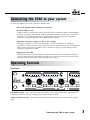
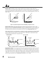
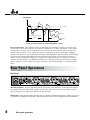
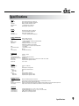
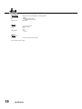
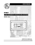
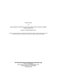
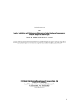
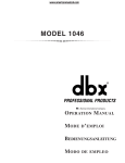
MODEL 1046
Operation Manual
Contents
Introduction................................................................................. 2
Inspection..................................................................................... 2
Warranty...................................................................................... 2
Connecting the 1046 to your system........................................... 3
Operating Controls....................................................................... 3
Rear Panel Operations.................................................................. 6
Applications.................................................................................. 7
Installation Considerations........................................................... 8
Specifications................................................................................ 9
Manual Contents
1
Introduction
Congratulations and thank you for your purchase of the dbx 1046 Quad Compressor Limiter. The dbx 1046 is
a high performance multifunctional unit designed to deliver all the flexibility and power that a professional
user demands. The dbx 1046 incorporates the new advanced dbx V2™ VCA for high system performance. We
recommend you take a moment to read through this Operation manual. It provides information that will assist
you in system set-up.
Inspection
Verify that the 1046’s package contains the following:
•
•
•
•
•
1046 Unit (according to Model number marked on package)
AC Power Cord
Operation Manual
Registration Card
4 Rack Mount Screws and Washers
If any of these items are missing, contact dbx customer service at (801) 568-7660.
Warranty
1. T he warranty registration card that accompanies this product must be mailed within 30 days after purchase
date to validate this warranty. Proof-of-purchase is considered to be the burden of the consumer.
2. dbx warrants this product, when bought and used solely within the U.S., to be free from defects in materials
and workmanship under normal use and service.
3. d bx liability under this warranty is limited to repairing or, at our discretion, replacing defective materials
that show evidence of defect, provided the product is returned to dbx WITH RETURN AUTHORIZATION from the
factory, where all parts and labor will be covered up to a period of two years. A Return Authorization number
must be obtained from dbx by telephone. The company shall not be liable for any consequential damage as a
result of the product’s use in any circuit or assembly.
4. d bx reserves the right to make changes in design or make additions to or improvements upon this product
without incurring any obligation to install the same additions or improvements on products previously
manufactured.
5. The foregoing is in lieu of all other warranties, expressed or implied, and dbx neither assumes nor authorizes
any person to assume on its behalf any obligation or liability in connection with the sale of this product.
In no event shall dbx or its dealers be liable for special or consequential damages or from any delay in the
performance of this warranty due to causes beyond their control.
2
Introduction
Connecting the 1046 to your system
To connect the 1046 to your system, refer to the following steps:
• Turn off all equipment before making any connections.
• Mount the 1046 in a rack
I nstall the 1046 in a rack with the rack screws provided. It can be mounted above or below anything
that does not generate excessive heat. Ambient temperatures should not exceed 113˚ F (45˚ C) when
equipment is in use. Although the unit is shielded against radio frequency and electromagnetic
interference, extremely high fields of RF and EMI should be avoided.
• Make audio connections via XLR, 1/4” TRS, or 1/4” TS plugs.
B
oth types of connectors for the inputs and outputs can be used for balanced or unbalanced
connections. The use of more than one connector at a time for the input/output pair could unbalance
balanced lines, cause phase cancellations, short a conductor to ground, or cause damage to other
equipment connected to the 1046.
• Apply power to the 1046
Connect the AC power cord to the AC power receptacle on the back of the unit. Route the AC power
cord to a convenient power outlet away from audio lines. The unit may be turned on and off via the
rear panel power switch or from a master equipment power switch.
Operating Controls
Front Panel
GAIN REDUCTION dB
30
-20
25
-10
20
15
10
6
INPUT / OUTPUT LEVEL dBu
3
CHANNEL ONE
0
-30
2:1
1
-24
3:1
-6
0
+6
-10
+10
I/O Meter
1:1
RATIO
+12
GAIN REDUCTION dB
THRESHOLD
+
+18
0
8:1
OverEasy
-40 dBu +20
THRESHOLD
-12
4:1
+10 1.5:1
PROFESSIONAL PRODUCTS
-18
+12
+10
30
+14
+6
COMPRESSOR
-10
20
15
+4
dBu OFF
PeakStopPlus
LIMITER
10
6
INP
3
CHANNEL TWO
0
+20 -30
Stereo
Couple
Bypass
-20 dB +20
OUTPUT GAIN
:1
-20
25
2:1
1
3:1
8:1
OverEasy
-40 dBu +20
THRESHOLD
RATIO
POWER: 25 WATTS
OUTPUTS
:1
COMPRESSOR
Compressor Threshold Control - This control sets the level above which compression occurs, and has a 60 dB
range.
CHANNEL FOUR
FUSE: REPLACE WITH SAME
OPERATING
-1
I/O Meter
1:1
+4 dBu
Connecting the 1046 to LEVEL
your system-10 dBV
-18
4:1
+10 1.5:1
Gain Reduction Meter - This 8 stage meter shows the amount of gain reduction due to both compression and/
or Intelligent Predictive Limiting™, displaying gain reduction from 0 to 30 dB.
TYPE FUSE AND RATING.
200-240V ATTENTION: UTILISER UN
50/60Hz FUSIBLE DE RECHANGE DE
MEME TYPE ET CALIBRE.
100-120V: 250mA 250V
SLOW BLOW
200-240V: T 125mA L 250V
100-120V
MADE IN USA
50/60Hz
MODEL 1046
-24
INPUTS
3
1:1
OUTPUT LEVEL (dB)
+20
+15
2:1
+10
4:1
+5
0
AM
−5
R
BE
:1
RED
Above Threshold
OverEasy Range
G
RE
EN
OverEasy® Switch - OverEasy® provides a smooth transition from the compressor’s linear region to the
−15
Threshold
compressed region.
ThisBelow
smooth
transition greatly reduces compression artifacts and allows higher compression
ratios while still −15
maintaining
characteristics of the signal. The switch lights to indicate OverEasy®
−10 −5
+15 +20
+10 natural
0 +5the
LEVEL
(dB)
processing is enabled. INPUT
When
conventional
hard knee processing is desired, disable the OverEasy® function. See
Figure 1 below.
−10
1:1 Unity
1:1
+20
+15
2:1
+10
4:1
+5
20:1
0
:1
-5
Rotation Point Threshold
-10
+15
2:1
+10
4:1
+5
0
−5
A
-15 -10
-5
0
G
GREEN
Below Threshold
−15
+5 +10 +15 +20
R
RED
:1
Above Threshold
OverEasy Range
RE
−10
-15
E
MB
EN
RED
Above Threshold
OUTPUT LEVEL (dB)
OUTPUT LEVEL (dB)
+20
Below Threshold
−15 −10 −5
0
+5 +10 +15 +20
INPUT LEVEL (dB)
INPUT LEVEL (dB)
Figure 1: Hard Knee Compression Curve and OverEasy® Compression
Curve.
1:1 Unity
+20
RED
Above Threshold
OUTPUT LEVEL (dB)
+15
Compressor Ratio Control - This control selects the ratio between
input and the output
levels for signals
2:1
above the level set by the COMPRESSION THRESHOLD control.+10It is adjustable between4:11:1 and ∞:1. Note, when
+5
OverEasy® processing is selected, the ratio transitions smoothly
from the linear to the20:1compressed region. As
0
the signal exceeds the threshold, the ratio approaches the ratio
set by the COMPRESSOR:1 RATIO control.
-5
Rotation Point Threshold
Figure 2 shows the effect of 2:1 compression on a signal as -10
it rises above and falls below the threshold. Below
GREEN
Below Threshold
-15 the output
the threshold the signal is not affected. Above the threshold,
signal increases by only half of the
increase (in dB) of the input signal level. In other words, with a 2 dB increase in input level, the output
-15 -10 -5 0
+5 +10 +15 +20
increases by only 1 dB, hence the 2:1 compression ratio.
INPUT LEVEL (dB)
Signal Level (dBu)
Signal Level (dBu)
10
0
10
Input Signal
0
Above Threshold
-10
-20
Input Signal
Above Threshold
-10
-20
-30
Below Threshold
Time
-40
-30
-40
Output Signal
Below Threshold
Time
Figure 2: Compression Effect on Signal Level with a 2:1 Ratio at a -20 dBu Threshold
Input/Output Level Meter - This 8-stage meter directly reads the input and output levels when the rear-panel
OPERATING LEVEL SWITCH is in the +4 dBu position. In the -10 dBV position, the input signal is boosted by
11.8 dB (the difference between +4 dBu and -10 dBV) to convert a semi-pro -10 dBV level signal to the professional +4 dBu internal level of the 1046, while the output signal is attenuated by 11.8 dB to convert back to a
-10 dBV level. Since the meter is calibrated for +4 dBu operation, it reads about 12 dB higher than the actual
input and output signal levels when the OPERATING LEVEL SWITCH is set to -10 dBV.
4
Operating controls
Input/Output Meter Switch - This switch selects the signal for metering by the INPUT/OUTPUT LEVEL METER.
The switch lights indicating the input signal is currently being sent to the meter. When the switch is in the out
position, the output signal is selected for metering, and the switch will not be illuminated.
Output Gain Control - This control sets the output gain of the compressor. It can be continuously adjusted
between -20 dB and +20 dB. Use this control to compensate for signal level loss due to compression and to
adjust the nominal output level of the unit.
Bypass Switch - This switch bypasses the unit completely, “hard-wiring” the input directly to the output, and
the signal is not processed in any way. The switch will light indicating that the unit is currently bypassed.
PeakStopPlus™ Level Control - This control sets the level to which the output signal is reduced whenever
it exceeds this level. It can be adjusted between +4 dBu and +22 dBu (OFF). This PeakStopPlus™ limiter
uses a propietary dbx two-stage limiting process. The first stage is the Instantaneous Transient Clamp™
which clamps the signal with a soft logarithmic clamp function. This logarithmic function assures that the
signal will not exceed the level set by the PeakStopPlus™ LEVEL control by more than 2 dB typically, and
that it will not introduce harsh artifacts. The second stage is a unique program limiter featuring Intelligent
Predictive Limiting™. Its function is to monitor the input signal and intelligently predict the amount of gain
reduction needed to keep the output signal below the ceiling set by the Instantaneous Transient Clamp™.
The PeakStopPlus™ limiter must come after the OUTPUT GAIN control. If the OUTPUT GAIN is set too high as
compared to the PeakStopPlus™ LEVEL control, continuous limiting can occur. While PeakStopPlus™ is typically
used as a protective function, creative effects can be achieved by intentionally driving the signal into heavy
PeakStopPlus™ limiting. Great care has gone into the design of the PeakStopPlus™ limiter to keep it acoustically
transparent. Appropriate use of it can protect your gear while keeping the signal free of artifacts.
PeakStopPlus™ Threshold (+) LED Indicator - This LED illuminates when the output signal exceeds the level
set by the PeakStopPlus™ LEVEL control indicating that PeakStopPlus™ limiting is occurring.
Figure 3 illustrates the protective action of the PeakStopPlus™ limiter. The signal with the thin line weight
represents an unaltered input signal. As you can see, peaks of the input signal exceed the clamping level. The
signal with the heavier line weight represents the output signal. The peaks of the input signal which exceeded
the clamping level are not allowed to exceed this level at the output. This instantaneous protective action is
invaluable for driver protection in speaker systems and for digital recording where it is desirable to record as
“hot” as possible, while still avoiding the disastrous result of running out of headroom. Following this clamping
action, Intelligent Predictive Limiting™ takes over, typically within 5ms, as long as the input signal continues
to exceed the PeakStopPlus™ threshold. This program limiter quickly attenuates the input signal to a level
safely below the clamping level, typically 2 dB lower than the clamping level. The PeakStopPlus™ level control is
calibrated to this lower level, so if an absolute ceiling is required, set the level 2 to 3 dB below the front panel
setting.
The attack and release times of the Instantaneous Transient Clamp™ are zero, while the Intelligent Predictive
Limiting™ attack and release times are program-dependent. That is, for larger excursions over the threshold, the
attack time speeds up, and for smaller excursions over the threshold, the attack time slows down. Similarly, for
large excursions over the threshold which cause more PeakStopPlus™ gain reduction, the release time increases
and is roughly proportional to the amount of gain reduction that occurred.
Operating Controls
5
Output Signal
}
Input Signal
Intelligent Predictive Limiting™
Attack Time
2 dB Typically
Release Time
Output Signal
Time
Figure 3: Protective Action of the PeakStopPlus™ Limiter
Stereo Couple Switch - These switches change the 1046 from four independent compressors into two stereo
compressors. In stereo mode, Channel 1 is the master and Channel 2 is its slave, and Channel 3 is the master
and channel 4 is its slave. Each of the Channel 2 and 4 controls and switch functions will be overriden and
controlled by the Channel 1 and 3 controls and switches, respectively, except for the I/O Meter and Bypass
switches. Also, Channel 2’s and 4’s Compressor Threshold, and PeakStopPlus™ Threshold meters will be disabled,
while these slave channels’ Gain Reduction meters will indicate the amount of gain reduction occurring, as
on their masters’ Gain Reduction Meters. All 4 channels have equal precedence as far as signal processing is
concerned. The dbx 1046 uses True RMS Power Summing™, an extremely accurate and musical way to combine
detector outputs in a stereo situation. The switch will light to indicate that the 1046 is in the Stereo Couple
mode.
Rear Panel Operations
Rear Panel
30
FUSE: T 300mA L 250V
AC Power Receptacle - Use the supplied AC cable to connect the unit to AC power. The AC receptacle includes
an integral pull-out fuse drawer which contains two fuses; the active fuse and a spare fuse. Replace the fuse
with the same type and rating only.as indicated on the rear panel.
Audio Inputs - Each channel features both XLR and 1/4” TRS electronically balanced inputs. Inputs may be used
in a balanced or unbalanced configuration. Note that the XLR and 1/4’ inputs may NOT be used simultaneously.
6
Rear panel operations
Audio Outputs - Each channel features both XLR and 1/4” TRS servo-balanced outputs. Outputs may be used
in a balanced or unbalanced configuration. Unlike the inputs both the XLR and the 1/4” outputs may be used
simultaneously. An output transformer option is available when very long cable distances are required (see
“Specifications”).
Operating Level Switch - This switch selects between a -10 dBV and +4 dBu nominal operating level. When
the switch is in the in position, a -10 dBV operating level is selected. When it is in the out position, +4 dBu is
selected. This switch affects both the input and the output levels.
Applications
Fattening Kick Drums and Compressing Other Drums
Weak, flabby kick drums often have too much boom, and not enough slap. To tighten them up, start with
the 1046 adjusted for a medium to high RATIO (e.g., 6:1), adjust the THRESHOLD control so that the GAIN
REDUCTION meters show 15 dB of gain reduction, then increase the RATIO if necessary. In OverEasy® mode,
the 1046 takes slightly longer to react than in Hard Knee mode, and will therefore emphasize the slap at the
beginning of the note and reduce the boominess of its body. The 1046 also works well for tightening snare
drums and tom toms and can be used with drum machines to effectively alter the character of any electronic
drum sound.
Raising a Signal Out of a Mix
Since reducing dynamic range increases the average signal level by a small amount, a single track can be raised
out of a mix by boosting its level slightly and applying compression. Start with a 2:1 RATIO and a relatively low
THRESHOLD setting (-20 dBu). Adjust both controls as necessary.
Compressors have also been used to bring vocals to the forefront of a mix in volume-restricted studios (e.g.
home studios). Start by adding a foam windscreen to the mic (if it doesn’t have one). Set the RATIO to 10:1 and
the THRESHOLD to -10 dBu. With your mouth approximately 2 inches from the mic, sing the vocal part, but with
less volume than normal. Use phrasing to give the part some intensity. An equalizer (e.g., a dbx 242 Parametric
Equalizer, dbx 30 Series Graphic Equalizers) or a vocal effects device (e.g., a dbx 290 digital reverb) can be
added to further define the performance.
Note: When compressing a stereo program with a 1046, the factors affecting a compression curve and
the actual RATIO and THRESHOLD settings are the same as those previously covered with reference
to single channels of program material. However, it will generally be found that large amounts of
compression are more audible in a mixed stereo program than they might be on the separate tracks that
were mixed to create the program.
Smoothing out Microphone Levels
When distance is created between the vocalist and the microphone there will be a variation in the signal level.
Start with low compression (around 2:1) to smooth out any variations. Limiting also benefits intelligibility by
allowing low-level input signals to be reproduced through the system at higher volume.
Smoothing out Musical Instrument Levels
Compression smooths out the variations of loudness among instruments. Using the 1046 can also increase the
instrument’s sustain. Compress the instrument’s output with a ratio of about 4:1.
Speaker Protection
Compressors are frequently used to prevent excessive program levels from distorting power amps and/or
Applications
7
damaging drivers in a sound-reinforcement system (whether you’re doing auditorium, church, or club sound
engineering, or are a mobile DJ, or like to push the limits of your home’s audio entertainment center). Set the
1046 for limiting (Hard Knee mode On, with a RATIO of 10:1 or greater) and adjust the THRESHOLD to provide
15 dB or more of compression (just a few dB below the input clip). For low-level signals, the 1046 won’t change
gain, but if large signals come along, the gain will be reduced to prevent clipping and save sensitive system
components from excessive heat buildup or other types of damage.
Note: PeakStopPlus™ Limiting can also be used to prevent speaker damage.
Preventing Digital Recording Overload
Some digital recorders and samplers produce audible distortion when they exceed their maximum operating level.
The 1046 can be used to ensure that audio input does not overload a digital recorder’s A/D (analog-to-digital)
converters. The 1046 can perform this function quietly enough for all digital media. To use the 1046 so that no
changes in gain occur unless an emergency arises (wildly excessive levels), set Hard Knee mode On, the RATIO to
∞:1, and the THRESHOLD highest level before digital overload.
Note: PeakStopPlus™ limiting can also be used to prevent raucous-sounding digital overload.
Installation Considerations
Hookups and Cabling: The 1046 is designed for nominal -10 dBV or +4 dBu levels. The 1046 can be used with
either balanced or unbalanced sources and the outputs can be used with either balanced or unbalanced loads,
provided the proper cabling is used.
Normal Balanced Connections for Inputs and Outputs
Connection
XLR TRS 1/4” Jack
Ground: Pin 1 Sleeve High: Pin 2 Tip
Low:
Pin 3 Ring Normal Unbalanced Connections for Inputs and Outputs
Connection
XLR TRS 1/4” Jack
TS 1/4” Jack
Ground: Pin 1 Sleeve Sleeve High: Pin 2 Tip
Tip
Low (ground):
Pin 3 Ring Sleeve Tie pin 3 to the ground for unity gain in/out of the 1046 when using unbalanced input connections to
balanced output connections or balanced input connections to unbalanced output connections. To do
otherwise won’t hurt the unit but will result in unmatched input to output levels, and the level control will
not be properly calibrated.
8
Installation considerations
Specifications
Input
Connectors:
Type: Impedance:
Max Input Level:
CMRR:
Output
Connectors:
Type:
Impedance:
Max Output Level:
Female XLR and 1/4” TRS (Pin 2 and tip hot)
Electronically balanced/unbalanced, RF filtered
Balanced > 50 kΩ, unbalanced >25 kΩ
> +24 dBu balanced or unbalanced
40 dB; Typically >55 dB at 1 kHz
Male XLR and 1/4” TRS (Pin 2 and tip hot)
Servo-balanced/unbalanced, RF filtered
Balanced 60Ω, unbalanced 30Ω
> +21 dBu, >+20 dBm balanced/unbalanced
System Performance
Bandwidth:
20 Hz to 20 kHz, +0/-0.5 dB
Frequency Response:
0.35 Hz to 200 kHz, +0/-3 dB
Noise:< -94 dBu, unweighted, 22 kHz measurement bandwidth
Dynamic Range:
> 118 dB, unweighted
THD+Noise:
0.009% typical at +4 dBu, 1 kHz unity gain
0.09% typical at +20 dBu, 1 kHz, unity gain
< 0.1% any amount of compression up to 40 dB, 1 kHz
IMD:
< 0.1% SMPTE
Interchannel Crosstalk:
< -85 dB, 20 Hz to 20 kHz
VCA:
dbx V2™
Stereo Coupling:
True RMS Power Summing
Compressor
Threshold Range:
Ratio:
Threshold Characteristic:
Attack/Release Characteristic:
Attack Time:
Release Time:
Output Gain:
Limiter
Threshold Range:
Ratio:
Limiter Type:
Stage 1:
Attack Time:
Release Time:
Stage 2:
Attack Time:
Release Time:
Function Switches
OverEasy®:
I/O Meter:
Bypass:
Operating Level (rear panel):
Stereo Couple:
-40 dBu to +20 dBu
1:1 to ∞:1
Selectable OverEasy® or hard knee
AutoDynamic™
Program-dependent, typically 15ms for 10 dB, 5 ms for 20 dB, 3 ms for 30 dB
Program-dependent, typically 125 dB/sec
-20 to +20 dB
+4 dBu to +22 dBu (off)
∞:1
PeakStopPlus™ two-stage limiter
Instantaneous Transient Clamp™
Zero
Zero
Intelligent Predictive Limiting™
Program-dependent, typically <5 msec
Program-dependent, typically 22 dB/sec
Activates the OverEasy® compression function.
Switches between monitoring input and output levels on the Input/Output Level meter.
Activates the direct input-to-output hard-wire bypass.
Switches the nominal operating level between-10 dBV and +4 dBu simultaneously for both input and output levels.
Couples channels in stereo pairs. Channels One and Three become the master channels.
Indicators
Gain Reduction8 segment LED bar graph at 1, 3, 6, 10, 15, 20, 25, and 30 dB
Input/Ouptut Level8-segment LED bar graph at -24, -18, -12, -6, 0, +6, +12, and +18 dBu
Limiter Threshold:
1 LED to indicate PeakStopPlus™ limiting
Function Switches:
LED indicator for each front-panel switch
Specifications
9
Power Supply
Operating Voltage:
Factory selected: 100-120 VAC 50/60 Hz or 200-240 VAC 50/60 Hz
Power Consumption:
30 Watts
Fuse:
100-120 VAC: T 300 mA L 250V
200-240 VAC: T 160 mA L 250V
Mains Connection:
IEC receptacle
Physical
Dimensions:
1.75” H x 19” W x 9” D
44.5 x 483 x 229 mm
Weight:
7.4 lbs.
3.4 kg
Shipping Weight:
9.8 lbs.
4.4 kg
Options
Output Transformer
Per Channel:
Jensen® JT-123-dbx or BCI™ RE-123-dbx
Note: Specifications subject to change.
10
Specifications