1
VHF LOW NOISE
PREAMP KIT
Ramsey Electronics Model No.
PR100
Boost up those weak signals without adding in unwanted noises!
The PR100 has a three section tuned circuit and a double helical
filter to allow only the desired signal to be amplified, while
attenuating signals outside the band. A perfect match for any 2
meter receiver!
• Extensive filtering for low noise operation, 1dB
noise figure!
• Three section tuned circuit and double helical filter
• Centered on 145 MHz and is 2.8 MHz wide
• 16dB Gain
• Perfect match for any VHF Receiver
• Powered through antenna feed line, or separately
• Runs on 12VDC
• Designed to fit inside of 1 1/2” PVC for quick and
easy mounting
PR100 y 1
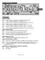
RAMSEY TRANSMITTER KITS
• FM100B Professional FM Stereo Transmitter
• FM25B Sythesized Stereo FM Transmitter
• MR6 Model Rocket Tracking Transmitter
• TV6 Television Transmitter
RAMSEY RECEIVER KITS
• FR1 FM Broadcast Receiver
• AR1 Aircraft Band Receiver
• SR2 Shortwave Receiver
• SC1 Shortwave Converter
RAMSEY HOBBY KITS
• SG7 Personal Speed Radar
• SS70A Speech Scrambler
• BS1 “Bullshooter” Digital Voice Storage Unit
• AVS10 Automatic Sequential Video Switcher
• WCT20 Cable Wizard Cable Tracer
• LABC Lead Acid Battery Charger
• ECG1 Heart Monitor
RAMSEY AMATEUR RADIO KITS
• HR Series HF All Mode Receivers
• QRP Series HF CW Transmitters
• CW700 Micro Memory CW Keyer
• CPO3 Code Practice Oscillator
• QRP Power Amplifiers
RAMSEY MINI-KITS
Many other kits are available for hobby, school, Scouts and just plain FUN. New
kits are always under development. Write or call for our free Ramsey catalog.
PR100 PREAMP KIT INSTRUCTION MANUAL
Ramsey Electronics publication No. MPR100 Revision 1.0
First printing: February, 1995
PR100 y 2
Ramsey Publication No. MPR100
Manual Price Only: $5.00
KIT ASSEMBLY
AND INSTRUCTION MANUAL FOR
VHF LOW NOISE
PREAMP KIT
TABLE OF CONTENTS
Introduction to the PR100 ............................. 4
How it Works ................................................. 4
Schematic ..................................................... 5
Parts Layout .................................................. 6
Strategy ......................................................... 7
Assembly Steps ............................................ 8
Alignment ...................................................... 11
Installation ..................................................... 12
Troubleshooting ............................................ 13
Warranty........................................................ 14
RAMSEY ELECTRONICS, INC.
590 Fishers Station Drive
Victor, New York 14564
Phone (585) 924-4560
Fax (585) 924-4555
PR100 y 3
INTRODUCTION TO THE PR100
This amplifier is a truly necessary piece of equipment for your 2 meter receive
applications. With 16dB of gain, you mount this up on your mast on the antenna
to boost those weak signals to a receivable level. This results in clear,
unbroken reception, and a more pleasant listening experience.
The filtering of the preamplifier is narrow enough only to allow the desired
frequency band through, while rejecting all others. This prevents many
problems associated with interference such as intermodulation and front end
overload. Having such a narrow bandwidth also reduces background noise that
would normally be present in wider band amplifiers.
Hookup is very simple in that the unit is powered through the same cable that
you receive your signals through. It is possible to ‘feed’ the 12VDC up the coax
cable to the preamplifier. No new wires to run and makes for less
weatherproofing.
The PC board was designed to fit within a 1 1/2” PVC pipe, so a simple
enclosure could be created out of one piece of pipe and two endcaps. Glued
together it can make for the perfect weatherproof enclosure.
HOW IT WORKS
There really isn’t much to the preamplifier if you look to the schematic at the
right. It mostly consists of filtering, and has only one active part, Q1. We will
start from the Antenna end of the preamp, and then on to the receiver end.
J1 and J2 is where the user can connect two different antennas. Some people
recommend that you use two turnstile antennas at right angles to each other for
good satellite imaging, if you’re using this with a weather satellite receiver. This
allows for good coverage of the horizons. Normally you will only use one of
these jacks.
From these jacks the unfiltered RF passes through C6, into the bandpass tank
circuit consisting of inductor L3 and capacitor C8. This tank circuit and the next
two are eventually tuned to be centered at 145 MHz. C4 allows some of the RF
from the first tank circuit to be allowed into the next, but is very small in
capacitance to offer a large reactance (resistance to AC). This high reactance
allows the tank circuits to perform their jobs better by giving them a higher Q
factor. This means that the spectrum of RF the tank circuits will allow through
becomes narrower due to the high Q.
PR100 y 4
The RF passes through two more tank circuits consisting of L4 and C9 in the
second, and C12 and L5 in the third. Every time the RF goes through an
additional tank circuit, the bandpass bandwidth of the RF is narrower. The
narrower the bandwidth is before the active component of Q1, the better.
The narrow bandpass allows Q1 to devote its amplification to just the desired
signals. This means that it doesn’t amplify nearly as much noise, and won’t
amplify signals outside of the bandpass area. Q1 amplifies the RF up to a
respectable level, where it is sent out to FL1, the dual helical filter.
With steep cutoff frequencies and low loss, FL1 has very good bandpass
characteristics for our preamp. This filter is essentially a series of tank circuits
that have very high Q, and is designed with a specific frequency band in mind.
It is tuned by the user to be centered at 145 MHz with the two coils inside.
L2, L1, and C1 allows the DC fed through the coax line to pass on to Q1 to
power it, while rejecting the RF so that the unit does not self oscillate. C3
blocks the DC from coming into the filters, but allows the RF down to the cable.
PR100 y 5
PARTS LAYOUT DIAGRAM
PARTS LIST
CAPACITORS
2 2.2pF ceramic capacitors (marked 2.2) (C4, C5)
1 10pF ceramic capacitor (marked 10) (C7)
3 8.2pF ceramic capacitors (marked 8.2) (C8, C9, C10)
1 22pF ceramic capacitor (marked 22) (C6)
1 100pF ceramic capacitor (marked 100, or 101) (C2)
1 .001uF ceramic capacitor (marked .001, or 102) (C3)
1 .01uF ceramic capacitor (marked .01, 103, or 10n) (C1)
FIXED RESISTORS
1 100 ohm resistor (brown-black-brown) (R1)
1 18 ohm resistor (brown-grey-black) (R3)
2 300 ohm resistors (orange-black-brown) (R4, R5)
1 47K ohm resistor (yellow-violet-orange) (R2)
SEMICONDUCTORS
1 2SC2498 or 2570 NPN UHF transistor (Q1)
INDUCTORS AND FILTERS
3 359-7787 Variable inductors (metallic cans with slug) (L3,L4,L5)
2 2.2uH inductors (green body with red-red-gold stripes) (L1, L2)
1 2 section helical filter, 145 MHz (Large metallic can with two
adjustments) (FL1)
CONTROLS, HARDWARE & MISCELLANEOUS
1 Type-F connector (J3)
1 PC Board
PR100 y 6
RAMSEY "LEARN-AS-YOU-BUILD ASSEMBLY STRATEGY"
We'll start building on the left side and work our way across, installing the lower
components up to the taller sized components. This will make our placing and
soldering of components easy.
Be sure to read through all of the steps, and check the boxes as you go to be
sure you didn't miss any important steps. Before you connect up the kit in a
hurry to see results, check all diodes, ICs, and capacitors for proper orientation.
Also check the board for any possible solder shorts or cold solder joints. All of
these mistakes could have detrimental effects on your kit - not to mention your
ego!
Kit building tips:
Use a good soldering technique - let your soldering iron tip gently heat the
traces to which you are soldering, heating both wires and pads simultaneously.
Apply the solder on the iron and the pad when the pad is hot enough to melt the
solder. The finished joint should look like a drop of water on paper, somewhat
soaked in.
Mount all parts on the top side of the board. This is the side that has no traces
or pads on it.
Part orientation - All parts in the kit are mounted at 90 degree angles to each
other, meaning that all parts are either parallel or perpendicular to the board.
Part installation - when parts are installed, the part is placed flat to the board,
and the leads are bent on the backside of the board to prevent the part from
falling out before soldering. The part is then soldered securely to the board, and
the remaining lead length is then clipped off. Since this is an RF project, make
sure that lead lengths are as short as possible, coming only second to
neatness.
In ALL PC board assembly steps, our word "INSTALL" means to do this:
• Insert the part, oriented or "pointed" correctly, into its holes in the PC
board.
• If helpful, gently BEND the part's wire leads or tabs to hold it into
•
•
place, with the body of the part snugly against the top side
("component side") of the circuit board.
Solder ALL wires or pins of the part.
Trim or "nip" all excess wire lengths extending beyond each solder
connection, taking care that wire trimmings do not become lodged in
solder connections.
PR100 y 7
ASSEMBLY INSTRUCTIONS:
1. Orient the PC board as in the Parts Layout Diagram. We will start with
the left hand side of the board, then go to the right.
2. Install C6, the 22pF ceramic capacitor (marked 22).
3. Install C8, a 8.2pF ceramic capacitor (marked 8.2).
4. Install C4, a 2.2pF ceramic capacitor (marked 2.2).
5. Install C9, a 8.2pF ceramic capacitor (marked 8.2).
6. Install C5, another 2.2pF ceramic capacitor (marked 2.2).
7. Install C10, yet another 8.2pF ceramic capacitor (marked 8.2).
8. Install L3, one of the metallic, square shaped inductors (marked 3597787) Make sure the holes line up with the pins before soldering.
9. Install L4, another one of the inductors (marked 359-7787)
10. Install L5, the last of the tunable inductors (marked 359-7787).
11. Install C7, a 10pF ceramic capacitor (marked 10).
12. Install Q1, the 2SC2498 NPN UHF transistor. This transistor has
excellent low noise characteristics, and can amplify signals into the
microwave region! Note that the pin out of this transistor is different than
that of a switching transistor, so mount it in the orientation as shown in
the Parts Layout Diagram. Make sure and use the correct holes for
mounting!
13. Install R2, a 47K ohm resistor (yellow-violet-orange). Note that it is a
stand up part. Keep the leads as short as possible, as well as neat!
14. Install R1, a 100 ohm resistor (brown-black-brown). This is also a
stand up resistor as well. Bend your leads as shown in the diagram.
15. Install C2, a 100pF ceramic capacitor (marked 100 or 101).
16. Install L1, one of the 2.2uH coils (green body, red-red-gold stripes).
17. Install R4, a 300 ohm resistor (orange-black-brown). Notice that this
is a lay down part.
PR100 y 8
18. Install C1, a .01uF ceramic capacitor (marked 103, .01, or 10n).
19. Install L2, another 2.2uH inductor (green body, red-red-gold stripes).
20. Install R3, a 18 ohm resistor (brown-grey-black).
21. Install C3, a .001uF capacitor (marked 102, or .001).
22. Install R5, a 300 ohm resistor (orange-black-brown).
23. Install FL1, the two section helical filter. Make sure
and mount it firmly to the board, and that all leads are
soldered correctly.
At this point we will check all solder joints for possible cold
joints or even worse, solder bridges. Make sure everything
looks neat and clean before continuing, since the better it
looks, the easier it is to find problems.
24. If you have the appropriate F-connectors, install J3, otherwise leave
this part out so that you can solder your connecting cable straight to the
PC board.
Congratulations! You have completed assembly of your PR100. Before
continuing on to install your new preamp, check all of your solder joints
thoroughly, as well as part orientation. You definitely don’t want to seal this
into a weatherproof container before you verify if it works or not!
PR100 y 9
ALIGNMENT:
Alignment is fairly simple if you follow these guidelines. The first step is to
back all of the lugs out of L3, L4, and L5 until they reach the top of the cans.
FL1 should be ok, and won’t need any adjusting.
1. Screw L3 in 8 turns.
2. Screw L4 in 8 turns.
3. Screw L5 in 8 turns.
If you have the equipment and the know-how, you can adjust the coils and
the helical filter further. You will need a spectrum analyzer and a frequency
generator to run at 145.52 MHz for best alignment.
Set the generator to 145.52 Mhz and tune the coils to get the greatest
amplitude and the best shape. Check the width of the bandpass to make
sure it is centered on 145.52 MHz, and is about 2.8 MHz wide. Sweep
through to check the shape of the bandpass, it should be close to flat across
the bandpass, if not you will need to tune the helical filter.
PR100 y 10
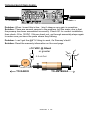
PREAMP INSTALLATION
This part of the manual assumes that you have a receiver or transceiver (if
using a transceiver a TR Switch is needed, like our RFS-1). This preamp
operates off a 12 volt DC supply which is connected to a 2.2 µH inductor
then to the center of the antenna cable near your radio(see diagram on next
page). Care has to be taken so that you don’t short out any connections.
Also a .01µF ceramic capacitor must be installed after the radios’ output and
before the connection to the 12 volt supply. This capacitor serves as a DC
block while allowing RF to pass through.
Installation of the preamp is fairly simple, yet there are a few considerations
you will wish to look into before you continue.
Any RF preamp should be located as close as possible to the antenna itself
for best performance. This is due to the losses involved in the cabling to the
antenna. Since a signal can be very weak at the antenna, it can be almost
nonexistent after it has gone through a length of cable. A non existent signal
doesn’t get amplified very well. If you boost the weak signal near the
antenna, it can be boosted to a high enough level that it can easily be sent
down the length of the cable.
PR100 y 11
THE PR100
Hookup is simple if you are using coax cable such as RG-58 or better 50 ohm
cable. Just run a piece from the jack marked RCVR (J3) on the PR100 to
the .01µF capacitor just before the radio. Then a short piece is needed to go
from the capacitor to the radio. Finally, you need to connect the Preamp to the
antenna and you are ready for testing.
HOOKUP EXAMPLE
Turn on your receiver, you should be able to pick up a weak signal with little
difficulty. If you are not receiving anything yet, check your 12 volt DC supply. If
you are still having troubles, test for the twelve volts present on the preamp,
then check the orientation of the preamp. If both are correct, you may need to
check your preamp for proper assembly, or even possibly your cabling for
opens. Consult the assembly instructions for some help on these matters.
PR100 y 12
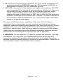
TROUBLESHOOTING GUIDE:
<-- To Antenna
To Radio -->
Problem: When I insert this in line, I don’t observe any gain in reception.
Solution: There are several causes to the problem, but the major one is that
the preamp has been assembled incorrectly. Check Q1 for correct installation,
then check J3 for 12VDC. If those check out, go through assembly steps again
to make sure you have the parts where they belong.
Problem: I can’t get the @#*%! thing to work, it’s Ramsey’s fault!
Solution: Read the warranty information on the next page.
+12 VDC @ 50mA
or greater
2.2 uH Coil
TO RADIO
TO ANTENNA
PR100 y 13
The Ramsey Kit Warranty
Please read carefully BEFORE calling or writing in about your kit. Most
problems can be solved without contacting the factory.
Notice that this is not a "fine print" warranty. We want you to understand your
rights and ours too! All Ramsey kits will work if assembled properly. The very
fact that your kit includes this new manual is your assurance that a team of
knowledgeable people have field-tested several "copies" of this kit straight from
the Ramsey Inventory. If you need help, please read through your manual
carefully, all information required to properly build and test your kit is contained
within the pages!
1. DEFECTIVE PARTS: It's always easy to blame a part for a problem in your
kit, however, customer satisfaction is our goal, so in the event that you do have
a problem, take note of the following. Before you conclude that a part may be
bad, thoroughly check your work. Today's semiconductors and passive
components have reached incredibly high reliability levels, and it’s sad to say
that our human construction skills have not! But on rare occasion a sour
component can slip through. All our kit parts carry the Ramsey Electronics
Warranty that they are free from defects for a full ninety (90) days from the date
of purchase. Defective parts will be replaced promptly at our expense. If you
suspect any part to be defective, please mail it to our factory for testing and
replacement. Please send only the defective part(s), not the entire kit. The part
(s) MUST be returned to us in suitable condition for testing. Please be aware
that testing can usually determine if the part was truly defective or damaged by
assembly or usage. Don't be afraid of telling us that you 'blew-it', we're all
human and in most cases, replacement parts are very reasonably priced.
2. MISSING PARTS: Before assuming a part value is incorrect, check the parts
listing carefully to see if it is a critical value such as a specific coil or IC, or
whether a RANGE of values is suitable (such as "100 to 500 uF"). Often times,
common sense will solve a mysterious missing part problem. If you're missing
five 10K ohm resistors and received five extra 1K resistors, you can pretty much
be assured that the '1K ohm' resistors are actually the 'missing' 10 K parts
("Hum-m-m, I guess the 'red' band really does look orange!") Ramsey
Electronics project kits are packed with pride in the USA. If you believe we
packed an incorrect part or omitted a part clearly indicated in your assembly
manual as supplied with the basic kit by Ramsey, please write or call us with
information on the part you need and proof of kit purchase.
3. FACTORY REPAIR OF ASSEMBLED KITS:
To qualify for Ramsey Electronics factory repair, kits MUST:
1. NOT be assembled with acid core solder or flux.
2. NOT be modified in any manner.
3. BE returned in fully-assembled form, not partially assembled.
PR100 y 14
4. BE accompanied by the proper repair fee. No repair will be undertaken until
we have received the MINIMUM repair fee (1/2 hour labor) of $25.00, or
authorization to charge it to your credit card account.
5. INCLUDE a description of the problem and legible return address. DO NOT
send a separate letter; include all correspondence with the unit. Please do
not include your own hardware such as non-Ramsey cabinets, knobs,
cables, external battery packs and the like. Ramsey Electronics, Inc.,
reserves the right to refuse repair on ANY item in which we find excessive
problems or damage due to construction methods. To assist customers in
such situations, Ramsey Electronics, Inc., reserves the right to solve their
needs on a case-by-case basis.
The repair is $50.00 per hour, regardless of the cost of the kit. Please
understand that our technicians are not volunteers and that set-up, testing,
diagnosis, repair and repacking and paperwork can take nearly an hour of paid
employee time on even a simple kit. Of course, if we find that a part was
defective in manufacture, there will be no charge to repair your kit (But please
realize that our technicians know the difference between a defective part and
parts burned out or damaged through improper use or assembly).
4. REFUNDS: You are given ten (10) days to examine our products. If you are
not satisfied, you may return your unassembled kit with all the parts and
instructions and proof of purchase to the factory for a full refund. The return
package should be packed securely. Insurance is recommended. Please do not
cause needless delays; read all information carefully.
PR100 y 15
VHF LOW NOISE PREAMPLIFIER
Quick Reference Page Guide
How it Works ....................................... 4
Schematic ............................................ 5
Parts Layout ........................................ 6
Strategy ............................................... 7
Assembly Steps ................................... 8
Troubleshooting ................................... 13
Warranty .............................................. 14
REQUIRED TOOLS
• Soldering Iron Ramsey WLC100
• Thin Rosin Core Solder Ramsey RTS12
• Needle Nose Pliers Ramsey MPP4 or RTS05
• Small Diagonal Cutters Ramsey RTS04
<OR> Technician’s Tool Kit TK405
ADDITIONAL SUGGESTED ITEMS
• Holder for PC Board/Parts Ramsey HH3
• Desoldering Braid Ramsey RTS08
• Digital Multimeter Ramsey M133
ESTIMATED ASSEMBLY
TIME
Beginner .............. 1.0 hrs
Intermediate......... 30 min
Advanced ............. 20 min
RAMSEY ELECTRONICS, INC.
Manual
590 Fisher Station Drive
Price Only: $5.00
Victor, New York 14564
Ramsey Publication No. MPR100
Phone
(585) 924-4560
Assembly
and Instruction manual for:
PR100
y 16
Fax
(585) 924-4555
RAMSEY MODEL NO. PR100
www.ramseykits.com
VHF Low Noise Preamplifier Kit