1
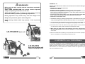
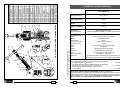
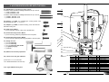
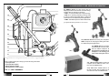
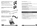
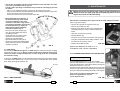
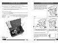
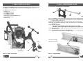
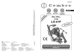
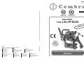
www.cembre.com
Cembre S.p.A.
Via Serenissima, 9
25135 Brescia (Italia)
Telefono: 030 36921
Telefax: 030 3365766
E-mail: [email protected]
www.cembre.it
Cembre España S.L.
Calle Verano, 6 y 8 - P.I. Las Monjas
28850 Torrejón de Ardoz - Madrid (España)
Teléfono: 91 4852580
Telefax: 91 4852581
E-mail: [email protected]
www.cembre.es
Cembre Ltd.
Dunton Park
Kingsbury Road, Curdworth - Sutton Coldfield
West Midlands B76 9EB (Great Britain)
Tel.: 01675 470440 - Fax: 01675 470220
E-mail: [email protected]
www.cembre.co.uk
Cembre AS
Fossnes Senter
N-3160 Stokke (Norway)
Phone: (47) 33361765
Telefax: (47) 33361766
E-mail: [email protected]
www.cembre.no
Cembre S.a.r.l.
22 Avenue Ferdinand de Lesseps
91420 Morangis (France)
Tél.: 01 60 49 11 90 - Fax: 01 60 49 29 10
B.P. 37 - 91421 Morangis Cédex
E-mail: [email protected]
www.cembre.fr
Cembre GmbH
Heidemannstraße 166
80939 München (Deutschland)
Telefon: 089/3580676
Telefax: 089/35806777
E-mail: [email protected]
www.cembre.de
cod. 6261139
This manual is the property of Cembre: any reproduction is forbidden without written permission.
11 M 134 E
Cembre Inc.
Raritan Center Business Park
181 Fieldcrest Avenue
Edison, New Jersey 08837 (USA)
Tel.: (732) 225-7415 - Fax: (732) 225-7414
E-mail: [email protected]
www.cembreinc.com
ENGLISH
Certified Quality
Management System
Certified Environmental
Management System
RAIL DRILL
TYPE
LD-1P-ECO
D
NTE
E
PAT
OPERATION AND MAINTENANCE
MANUAL
WARNINGS
APPENDIX “A”
– Before using the drill, carefully read the instructions contained in
this manual.
SAVE THESE INSTRUCTIONS: this manual contains important
safety and operating instructions for the drill.
– STOP THE ENGINE when servicing the drill: before removing
the broach cutters, spiral bits, positioning templates etc.
– During operation keep hands away from the danger zone.
– Always wear protective glasses and work gloves.
– Avoid wearing clothes which may present a risk to personal
safety.
Factors which influence the number of holes that can be made according to the
cutter used:
– Hardness of the material to be drilled.
– Thickness to be drilled.
– Stability of the drill clamping and correct assembly of the drill cutters.
– Suitable lubrocooling (lubrication/cooling) to keep the temperature of the cutter.
low so as not to compromise the efficiency of the cutting edges, whilst at the same
time facilitating the removal of swarf.
– Contact time of the cutting edges of the cutter with the material to be drilled;
bear in mind that the faster the hole is made the greater the efficiency.
– Observance of these basic rules:
1) Commence drilling by exerting light pressure on the advance lever, progressively increasing and then relaxing it when the cutter is in the exit phase.
2) Avoid pressure surges and advance according to the diameter of the drilling diameter,
to avoid scratching the material or damaging the cutting edges of the cutter.
3) Remember that a cutter with efficient cutting edges requires a lower pressure than
one with which a certain number of holes have already been made.
4) When holes are made close to raised lettering on the rails, commence drilling
with very light pressure until the lettering disappears, to avoid possible breakage
of the cutter.
LD-1PN-ECO basic drill
5) Bear in mind that when operating on very hard rails, as in the case of quality 1100
steel, it is advisable to increase the lubrocoolant flow rate.
15. RETURN TO Cembre FOR OVERHAUL
LD-1P-ECO
basic drill complete with
railweb clamping device
1
In the case of a breakdown contact our Area Agent who will advise you on the problem
and give you the necessary instructions on how to dispatch the drill to our nearest service
Centre; if possible, attach a copy of the Test Certificate supplied by Cembre together
with the drill or, if no other references are available, indicate the approximate purchase
date and the drill serial number.
34
Qty
1
1
1
1
2
2
2
2
2
4
2
4
1
1
1
1
1
1
1
1
1
1
1
2
2
1
2
1
1
1
1
1
1
1
1
Description
Spacer
Blocking screw
Complete bush
Spring support spacer
Spring
M 5 self-locking nut
Pin
ø 8x50 cilindrical pin
M5 ball dowell
M 6x18 screw
M 8x25 screw
ø 8 elastic washer
ø 4x10 cylindrical pin
ø1,8x35 split pin
TDB 1 termination
ø1,8x35 split pin
TDB 6 terminatin
Split pin
TDB 3 termination
ø10 circlip
Pin
Left support shoulder
Right support shoulder
Blocking side plate
Pin
M 8x10 grub screw
Handgrip
Hand-wheel
Blocking screw
Spacer
Bush
Cup spring
ø 2,5x16 split pin
Blocking support
Reference pin
1. GENERAL CHARACTERISTICS
Code N° Item
FIG. 32 – DBG-F2 RAIL WEB CLAMPING DEVICE
29
27
26
25
31
33
36
23
24
19
32
28
34
11
13
21
22
18
20
35
14 15
10
37
16
01
02
04
05
06
03
17
07
Drilling capacity (*):
∅ 7 ÷ 40 mm
Speed without load:
270 rpm
Weight:
15,7 kg
Weight with DBG-F2:
18,9 kg
Gear sump
Recommended oil:
(*) with broach cutters on thicknesses up to 50 mm
with special spiral bits on thicknesses up to 45 mm
37
36
35
34
33
32
31
29
28
27
26
25
24
23
22
21
20
19
18
17
16
15
14
13
11
10
09
08
07
06
05
04
03
02
01
6001155
6002871
6001762
6001768
6001769
6180201
6001776
6760378
6340612
6900314
6900348
6650144
6760222
6140082
6001138
6140082
6001775
6140080
6001137
6040421
6001156
6001907
6001906
6001757
6001772
6340160
6380310
6001150
6001151
6001659
6001152
6520422
6140085
6001145
6001281
08
09
33
LD-1PN-ECO
Combustion engine:
Type:
Model:
Displacement:
Power (SAE J1349):
Fuel tank capacity:
Clutch:
Start:
Ignition:
Spark plug:
Fuel:
Fuel consumption:
Emissions:
SHELL SPIRAX S4 TXM or
MOBIL SUPERMULTIGRADE 10-30-SAE or equivalents
2-stroke, horizontal shaft, single cylinder
KAWASAKI TJ45E
45,4 cm3
1,4 kW (1,9 HP) / 7500 rpm
0,9 litres
centrifugal with automatic intervention
by rope pull
solid state ignition (none breaker)
NGK BPMR7A or equivalents
2% (1:50) oil/petrol mixture (see § 8)
470 g/kW.hr / 350 g/hp.hr
according to "Phase 2" EPA regulation engines class V and
European Directives 97/68/EC, 2001/63/EC and 2002/88/EC
Acoustic Noise (Directive 2006/42/EC, annexe 1, point 1.7.4.2 letter u)
– The weighted continuous acoustic pressure level equivalent
A at the work place LpA is equal to ............................................................ 99,5 dB (A)
– The maximum value of the weighted acoustic displacement
pressure C at the work place LpCPeak is equal to ..................................... 116,3 dB (C)
– The acoustic power level emitted by the machine
LWA is equal to......................................................................................... 107,6 dB (A)
Risks due to vibration (Directive 2006/42/EC, annexe 1, point 2.2.1.1)
Tests carried out in compliance with the indications contained in UNI ENV 25349 and
UNI EN 28662 part 1st Standards and under operating conditions much more severe than
those normally found, certify that the weighted root mean square in frequency of
the acceleration the upper limbs are exposed is 4,36 m/sec2 max.
2
2. ACCESSORIES SUPPLIED WITH THE DRILL
11
2.1) Guide bits for controlling the cooling system:
for broach cutters suitable for drilling thicknesses of up to 25 mm
– 1 pc PP 1, diameter 7 mm
– 1 pc PP 2, diameter 8 mm
for broach cutters suitable for drilling thicknesses of up to 50 mm
– 1 pc PPL 1, diameter 7 mm
– 1 pc PPL 2, diameter 8 mm
12
13
2.2) Spacer, type DPE, for controlling the cooling system with
special spiral bits, diam. 7 ÷ 27,5 mm.
14
2.3) Adaptor, type ARE, for external cooling, to be used with the
SR 5000 cooling unit.
15
2.4) Grub screw, M8x10
– 4 pcs for clamping cutters or bits on the spindle shaft.
16
17
2.5) Socket head cap screws, M6x16
– 4 pcs for securing positioning templates to the front plate.
18
2.6) Socket head cap screws, M6x25
– 4 pcs for securing special positioning templates to the front plate.
19
2.7) Range of tools:
– 1 pc 5 mm allen key
– 1 pc 6 mm allen key
– 1 pc 4 mm allen key with handle
– 1 pc sparkle plug key
– 1 pc brush
20
21
22
23
2.8) Measure for mixture preparation.
24
2.9) 100 ml oil for the gear reduction.
6001209
24
6900060
23
6001731
22
6001198
21
2870261
20
6001146
19
6340160
18
6001397
17
6001195
16
6003754
15
6003755
14
6003613
13
Code N° Item
(Accessories 2.1 to 2.9 are included
in the “Kit of accessories”code 6001356).
2.10) Type SR5000 cooling unit.
3
32
Magnetic cap
Screw M 4x8
Guard
Lubricator
Front plate
Drilling spindle
M8x10 grub screw
Complete air valve
Level gauge
Reservoir+valve cap
Starting handgrip
Engine
Description
1
2
1
1
1
1
2
1
1
1
1
1
Qty
6003753 12
6003752 11
6380330 10
6003612 09
6003034 08
6001166 07
6490050 06
6001941 05
6360480 04
6001176 03
6001428 02
6001950 01
Code N° Item
Air cleaner element
1
Spark plug
1
Handle
1
Complete handgrip
1
Cap
1
Accelerator lever
1
Carriage handle
1
Complete spindle lever
1
O-ring
1
Lever release pawl
1
Complete cooling connection 1
Body
1
Description
Qty
3. ACCESSORIES TO BE ORDERED SEPARATELY
3.1) DBG-F2 device (*) with moving arm for
clamping the drill to the rail web and track fittings,
complete with the following end pieces:
– TDB 1: for switch blades and compound frogs.
– TDB 3: for repairing (adjusting) existing holes
on rails for subsequent application of electrical
connections and for additional special applications.
– TDB 6: standard end piece for rails and stock rails.
10
09
(*) Supplied with drilling machine ref. LD-1P-ECO
08
07
06
TDB 1
05
TDB 6
TDB 3
3.2) DBG-LF2 device with moving arm complete with
TDB 7 end piece for clamping the drill to girder rails and
for additional special applications.
04
03
02
TDB 7
3.3) DBSN device for clamping the
drill to flange rails, for use in conjunction
with the MPAF templates. Using
this device the rail drill can remain
clamped in the drilling position
even when trains pass over it.
01
The guarantee is void if parts used are not Cembre original spares.
When ordering spare parts always give the following information:
- spare part code
- spare part description
- drilling machine model
- drilling machine serial number
3.4) “VAL LD” metal case for storing the drill
complete with the DBG-F2 device, VAL MPA
tool case and DBSN devide.
3.4.1) “VAL LD-L” metal case for storing
the drill complete with the DBG-LF2 device,
VAL MPA tool case and DBSN devide.
FIG. 31 – DRILL ASSEMBLY
31
4
13.2.6) Checking of screws
– Check and re-tighten all screws where necessary.
3.5) Templates for positioning the drill on the rails and
stock rails to enable drilling to be carried out according to the
provisions of railway boards standards:
e.g.:
– MPAF UIC54 on DRILLING AXIS of 54E1 rail
– MPAF UIC60 on DRILLING AXIS of 60E1 rail
13.3) SPECIAL MAINTENANCE OF THE DRILL
The special maintenance operations require the intervention of qualified personnel only,
please contact Cembre (See § 15).
• Note: Contact Cembre for selection of specific application
accessories (e.g.: positioning templates for other rail profiles).
13.4) STORING THE DRILL FOR LONG PERIODS
–
–
–
–
–
Completely empty the fuel tank.
Start the engine and let it run until it stops, so that all fuel is exhausted from the machine.
Remove the spark plug.
Pour 3-5 cm3 of oil into the cylinder.
Repeatedly pull gently on the starting rope so that the dispersion of the oil in the cylinder
is achieved reinstall the spark plug.
– With a clean cloth wetted with engine oil, than clean all metal parts of the machine.
– Store the drilling machine in its appropriate case or in a dry environment, protecting it
against accidental damage and dust.
3.6) MPAU universal positioning template suitable both for
repairing existing holes on various fittings, and for drilling
disused rails.
3.7) SPA positioning plates for drilling rail heads with a centre-to-centre
distance established in the Railway
boards standards, without the need for
marking out; for use in conjunction with
the MPAF ... positioning templates.
14. WARNINGS
14.1) Regularly check for correct tightening (torque) of the fixing screws of the drill cutters
and the positioning templates.
14.2) Avoid pressure jolts on the advance lever during drilling.
14.3) Always make sure that drilling swarf is properly removed before starting to drill a
new hole.
14.4) Incomplete clamping of the drill on the rail to be drilled may lead to the breakage or
accelerated wear of cutters and damage to the spindle shaft bearings.
14.5) If it is necessary to operate the drill without the cutter inserted, remove the locking
grub screws from the spindle shaft.
14.6) Avoid leaving the SR 5000 tank under pressure and exposed to sunlight for long
periods of time.
14.7) Should the DBG-F2 clamping device be removed make sure, by reassembling it,
the two blocking screws are firmily fastened.
3.8) MRF clamp to be applied as a reference to the
head of rails for use, in conjunction with the SPA ...
connecting plates, for in-line drilling of the rail heads,
with established centre-to-centre distance.
3.9) VAL MPA metal box
suitable for accommodating
accessories 3.5 - 3.11.
5
30
3.10) Broach cutters
13.2.4) Spark plug cleaning (Ref. to Fig. 29)
– Disconnect the spark plug lead and with a spark plug key remove the spark plug.
– Clean the electrode, taking care not to damage the insulation.
– Check and adjust if necessary the electrode gap. (0.6 mm - 0.7 mm).
– Install and tighten the spark plug to 14 Nm, then connect the spark plug lead.
– In case of plug replacement, use type NGK BPMR7A or equivalent:
BOSCH WSR5F / DENSO W22MPR-U / CHAMPION RCJ6Y.
BROACH CUTTERS FOR RAILS IN STEEL QUALITY 700-900-1100 (UIC 860.0)
Ø
mm
13,5
14
15
16
17
18
19
20
21
22
23
24
25
26
27
28
29
30
31
32
33
34
35
36
37
38
39
40
FIG. 29 – SPARK PLUG CLEANING
Spark arrester
13.2.5) Spark arrester cleaning (Ref. to Fig. 30)
– Remove the spark arrester from the exhaust
opening.
– Clean deposits from the spark arrester screen by
brushing it.
– Relocate the spark arrester.
FIG. 30 – SPARK ARRESTER CLEANING
SHORT RANGE
Broach cutter
A
A
A
A
A
A
A
A
A
A
A
A
A
A
A
A
A
A
A
A
A
A
A
A
A
A
A
A
135
140 *
150 *
160
170
180
190
200
210
220
230
240
250
260
270
280
290
300
310 *
320
330
340 *
350 *
360 *
370 *
380 *
390 *
400 *
Guide bit
LONG RANGE (L max = 88mm)
Broach cutter
Guide bit
Ref. PP 1
Ref. PP 2
MAX DRILLING THICKNESS
25 mm
A
A
A
A
A
A
A
A
A
A
A
A
A
A
A
A
A
A
A
A
A
A
A
A
A
160L
170L
180L
190L
200L *
210L
220L
230L
240L
250L
260L
270L *
280L
290L *
300L
310L *
320L
330L
340L *
350L *
360L *
370L *
380L *
390L *
400L *
Ref. PPL 1
Ref. PPL 2
* Contact Cembre for availability of these broach cutters.
Every 50 hours of operating
MAX DRILLING THICKNESS
50 mm
Broach cutter resharpening must be carried out in compliance with appropriate methods of operation
which provide the best result.
29
6
3.11) Spiral bits
13.2) ROUTINE ENGINE MAINTENANCE
13.2.1) Fuel Tank Cap
A breather passage is incorporated in the tank cap.
If this passage is clogged, the fuel will not flow into
the carburetor, causing problems with starting or
running the engine. At the same time, make sure
that the base of the breather assembly is fitted firmly
into the groove inside the tank cap, as shown.
ø
h
APED...
FIG. 1
L max
APE...
Breather
Gancio
assembly
13.2.2) Fuel filter cleaning (Ref. to Fig. 27)
– Pick the grommet out of the fuel tank and remove the fuel filter assembly from the fuel tank
together with the grommet and the fuel tube to keep dust, entering from the fuel filter.
– Clean the fuel filter assembly in a bath of high flash-point solvent.
– Dry the fuel filter assembly before reassemble.
Improper use of solvents can result in fire or explosion.
ø
FIG. 2
Breather
Sfiato
passage
Breather
Fuel tank
Membrana
Serbatoio
Every 20 hours of operating
L max
Tank
cap
Tappo
SPECIAL SPIRAL BITS FOR RAILS IN STEEL QUALITY 700 - 900 - 1100 (UIC 860.0)
PE 70
PE 71
PE 80
PE 85
PE 90
PE 95
PE 100
PE 110
PE 120
PE 130AR
PE 135AR
76
72
1,2 APED 70
APED 80
76
1,4 APE 90
APE 95
APE 100
APE 110
APE 120
1,6
APED 130
APED 135/165
Ø
mm
14
16
17
17,5
18
19
2
21
22
24
27,5
1
PE 140
PE 160
PE 170AR
PE 175
PE 180
PE 190AR
PE 210AR
PE 220
PE 240AR
PE 275AR
L
h
max mm
mm
76
Adaptor
ref.
1,6 APED 135/165
88
85
special high quality spiral bit.
7
7,1
8
8,5
9
1 9,5
10
11
12
13
13,5
Adaptor
ref.
Spiral Bit
ref.
(*)
(*) PE... AR:
Ø
mm
L
h
max mm
mm
Figure
Figure
Tube
Spiral Bit
ref.
(*)
88
Fuel tank
Transparent
overflow tube
Filter
FIG. 27 – FUEL FILTER CLEANING
– Special spiral bits in the PE range allow automatic cooling by means of the SR 5000 unit supplied
with the drilling machine.
– All spiral bits in the PE range allow drilling of thicknesses up to 45 mm.
13.2.3) Air filter cleaning (Ref. to Fig. 28)
– Manually remove the holding screws of the air
cleaner cup.
– Remove the filter element.
– Wash the filter element in detergent and water and
dry it thoroughly.
– Reassemble all parts.
Operating in dusty condition may require more
frequent maintenance than above.
Do not operate the engine with air filter removed.
The drilling bits indicated in the tables guarantee optimum results. For bits of other types,
check the dimensional compatibility (particularly the size of the attachment and the length).
3.12) LR2 BIODEGRADABLE LUBROCOOLANT
3 litre container to be used in a 5-10 % solution, for optimum operation of broach cutters
and spiral bits.
3.13) LR3 ANTIFREEZE CONCENTRATE
3 litre added to the lubrocoolant mixture in the right concentration will
maintain the lubrocoolant mixture fluid in negative temperature conditions.
Grommet
3l
FIG. 28 – AIR FILTER CLEANING
7
28
13.1.2) Removal of metal residues from the crankcase
When the drill is positioned as shown in Fig. 26c
unscrew the cap with magnetic insert (24) on
which any metal residues present in the oil will
have collected. Carefully clean the magnetic
insert with a clean rag and screw it back in to
the appropriate housing.
4. COOLANT UNIT TYPE SR5000
24
FIG. 26c – REMOVAL OF
METALLIC WASTE
Every 50 hours of operation
13.1.3) Checking of screws.
– Check and re-tighten all screws where necessary.
13.1.4) Lubrication (Ref. to Figs. 31 and 32)
– Lubricate the spindle support housing by means of the appropriate lubricator (21), the
screw (07) of the DBG-F2 clamping device.
13.1.5) Coolant filter cleaning (Ref. to Fig. 26d)
The coolant circuit of the drilling machine is provided with anti-impurity filter; should an
evident decrease of the flow of the lubrocoolant occur, it could be necessary to clean the
filter in the following way:
– Using a 14 mm key, unscrew the coupling (02).
– Extract the filter and clean it carefully.
– Reassemble the filter into the coupling (02) as shown in the Fig. 26d and fully tighten
the coupling.
The type SR5000 coolant unit consists of a tank complete with tube and maximum pressure valve (01) fitted with a pump device for pressurisation, which must be connected to
the attachment (35) on the drill by means of its quick-coupling (03).
The delivery and shut-off of the lubrocoolant are controlled automatically when
drilling with a broach cutter from the position of the guide bit; when drilling with a
spiral bit, delivery and shut-off of the fluid must be effected manually by operating
the tap (02). The use of the lubrocoolant supplied by Cembre, in the recommended
concentrations, guarantees optimum use of the drilling tools.
Consumption of the lubrocoolant depends both on the variable degree of opening
of the tap (02) and the inner pressure of the tank: it is therefore advisable to open
the tap a little when the tank is at maximum pressure, while it must be fully opened
when the pressure in the tank is low.
When using the coolant system, pay careful attention to the instructions on the tank label.
Warning:
• When the tank is not under pressure, check that the bush on the maximum pressure valve is screwed right down.
• To fill tank with lubrocoolant, turn handle anticlockwise approximately 2 turns to
release handle locking mechanism. Remove handle/piston assembly from tank.
Detail of the
max pressure valve
17 – Vent valve
35 – Attachment valve
01 – Tank complete with tube
and max. pressure valve
02 – Tap
03 – Quick-coupling
01
anti-impurity filter
02
02
FIG. 26d – COOLANT FILTER CLEANING
27
FIG. 3 – COOLING UNIT
8
03
35
17
• The rail drill is equipped with the cooling attachment valve (35) and a vent valve
(17) which are located as shown (Fig. 3).
If under certain operating circumstances they need to be interchanged, proceed
as follows:
– With a 17 mm hexagonal spanner, unscrew the vent valve from its seat.
– Using the 4 mm Allen key provided with the drill, remove the appropriate cooling valve
from its seat and fit into the vent valve seat.
– Fit the vent valve into the removed coolant valve seat.
13. MAINTENANCE
Before you service or remove parts, stop the engine and allow it to cool.
Always remove the spark plug cap from spark plug when servicing the
engine to prevent accidental starting.
• When temperatures fall below 0° C
–
–
–
–
the lubrocoolant may freeze which
could cause damage to the seals
contained in the drill cooling system.
It is therefore advisable, when storing
the drilling machine, to empty the
lubrocoolant system completely.
Proceed as follows (Fig. 4):
Disconnect the quick coupling (03)
from the coolant attachment (35) on
the drilling machine.
Tilt the machine so that the coolant
attachment is at its lowest point allowing for natural drainage.
Operate the advance lever (36) to
advance and retract the drilling spindle.
Gently shake the machine to establish
expulsion of all fluid.
After the first 10 operating hours, proceed with oil sump change, as follows
(Ref. to Fig. 26a and 26b):
– Remove the cap with the magnetic insert (24).
– Remove the oil filler cap (08).
– Make sure that all the oil comes out by slightly tilting
the drilling machine in order to make the operation
easier.
08
– Clean the cap (24) (see § 13.1.2).
– Reassemble the cap .
– Fill up the oil sump to the level indicator (see § 13.1.1)
using the oil supplied with the drilling machine; it will
be necessary to use about 100 ml.
FIG. 26a
– Replace the oil filler cap (08).
FIG. 4
4.1) ARE adapter
For use with the SR5000 cooling unit. The ARE adapter is inserted in the quick-coupling
of the tank tube (Ref. to Fig. 5). May be used to provide manual external cooling when
cutters are used to enlarge existing holes or when using spiral bits not designed
for automatic cooling.
If necessary, the ARE adapter can also be used to clean various parts of the drill, by means
of the lubrocoolant pressure jet, e.g. parts such as the tool clamping seat in the spindle
shaft, seats for the jig fixing screws, etc.
ARE adapter
Ensure that disposal of used oil is in
accordance with current legislation.
13.1) ORDINARY MAINTENANCE OF THE MACHINE
Every 20 hours of operation
13.1.1) Topping up oil (Ref. to Fig. 26a and 26b)
With the drill switched off and placed on a flat surface,
check the oil level in the crankcase by looking through the
transparent inspection cover (16).
The level must be approximately half way up the cover; if the
level is low, top up the oil by unscrewing the cap (08) at the
top of the crankcase and adding the quantity of oil required.
Only use the oil grade recommended in § 1.
Never use regenerated or used oil.
The oil must be clean.
FIG. 26b
FIG. 5 – ARE ADAPTER
9
16
26
24
5. SPINDLE ADVANCE LEVER
12. STORING THE DRILL
When the work has been completed, store the drill by proceeding as follows:
12.1) Depressurise the tank of the SR5000 coolant unit (see § 4), close the tap (02) on
the tube from the tank and disconnect the quick-coupling (03).
12.2) Carefully clean the drill, particularly in the spindle area, removing machining waste
(swarf, etc.) and any deposits of lubricating coolant.
The spindle is advanced by moving the lever
(36) (See Fig. 6a). The lever is fitted with
a release pawl (39) which, when pressed,
renders it independent of the hub and hence
the spindle; the operator can therefore easily
vary the angular position of the lever without
movement of the spindle (Fig. 6b).
12.3) Fully withdraw the spindle.
12.4) Place the drill and the SR5000 cooling unit in a sealed place free from dust, moisture
and the risk of accidental impact.
otection Cembre recommends the use of the VAL LD metal case designed
For better protection
ose (see § 3.2), which enables
e
for this purpose
the drill to be located and to be locked in the
case by means
ans of DBG-F2 clamping device. A suitable
suita
housing is also provided in this
VAL LD for the VAL MPA box containing the most commonly used accessories.
a
FIG. 6
6a - Moving the lever (36) towards the operator;
corresponding advance of the spindle.
DBSN
VAL MPA
6b - With the release pawl (39) pressed, the lever is
released from its hub and can repeat the previous travel without the spindle moving.
DRILL
6c - With the hub released, moving the lever
towards the operator causes a corresponding advance of the spindle.
FIG. 7
5.1) Adjustment of the advance lever
The movement of the lever must never be loose.
For adjustment proceed to tighten it by loading
the cup springs by means of the associated
self-locking nut, after removing the protective
cap (see Fig. 7).
VAL LD
FIG. 25
STORAGE CASE
25
10
02
6. PREPARING THE DRILL
For clarity the drilling machine
is not shown.
STOP THE ENGINE when servicing the drill: before removing
the broach cutters, spiral bits, positioning templates etc.
6.1) Assembling broach cutters (Ref. to Figs. 8-11).
6.1.1) Insert the guide bit in the cutter from the side of the spigot.
6.1.2) Using the lever (36), position the spindle shaft (07) so that both grub screws (18)
become accessible and sufficient space is provided to insert the cutter; if necessary
rotate the spindle shaft manually and sufficiently by inserting the 4 mm allen
key in the appropriate intermediate gear housing (33) in the crankcase of the drill
(see Fig. 11).
6.1.3) Insert the cutter in the spindle shaft so that the two engaging dogs on the cutter
spigot line up with the grub screws (18).
6.1.4) Clamp the cutter by fully tightening the grub screws using the 4 mm allen key.
6.1.5) Check that the guide bit slides freely by applying slight pressure on it.
Engaging dogs
Origin of the distances
Short type broach cutter
Maximum drilling thickness: 25 mm
18
Guide bit PP...
07
02
Origin of the distances
Guide bit PPL ...
Long type broach cutter
Maximum drilling thickness: 50 mm
FIG. 8 – ASSEMBLING BROACH CUTTERS
6.2) Assembling special spiral bits (Ref. to Figs. 9 - 11)
6.2.1) Using the advance lever, position the spindle shaft so that both grub screws become
accessible and sufficient space is provided to insert the spiral bit; if necessary rotate
the spindle shaft manually and sufficiently by inserting the 4 mm male hexagon
key in the appropriate intermediate gear housing (33) in the crank-case of the drill
(see Fig. 11).
11
FIG. 24 – POSITIONING
24
11.2) Drilling in line with the rail heads (Ref. to Figs. 23-24)
11.2.1) Fit the MPAF... positioning template corresponding to the rail to be drilled (see § 7.3).
11.2.2) Fit the MRF clamp on the head of the rail, keeping it in contact with the rail
head at a point which defines the origin of the drilling centres, by locking it in position
with the lever. The lever is provided with a return pushbutton for moving in any
direction after locking. (See Fig. 23)
11.2.3) Insert the SPA... positioning plate so that the curved part is facing upwards.
11.2.4) Insert the locking pin (02) in one of the two holes of the connection plate.
11.2.5) With the spindle fully withdrawn, position the drill on the rail close to the MRF
clamp, without locking the spindle.
11.2.6) Slide the drill so that:
– the curved end of the SPA... plate is flush against the MRF clamp on the
side identifying the origin of the distances.
– the MPAF... positioning template is flush against the locking bolt (02)
(see Fig. 24).
11.2.7) Clamp the drill in this position by tightening the handwheel fully and commence
drilling (see § 10.1).
11.2.8) To drill the second hole in the rail, repeat operations 11.2.6 - 11.2.7 with the
locking pin (02) inserted in the second hole of the SPA... plate.
6.2.2) Insert into the spindle shaft, the DPE spacer required to activate the cooling device.
If necessary to use APE... adapter (see pag. 7) the bit must first be fitted in the
corresponding APE adapter and locked with the appropriate grub screw.
Then the DPE spacer may be inserted.
Note: Adapters type APED… do not require use of DPE spacer.
6.2.3) Insert the bit-spacer unit in the spindle shaft so that the two engaging dogs on the
bit spigot line up with the grub screws. Press the bit-spacer unit home against
the inner seat of the spindle: this will enable the DPE spacer to open the cooling
circuit (see Fig. 10).
6.2.4) Clamp the bit by fully tightening the two grub screws (18) using the 4 mm male allen
key.
APE ...
18
Bits PE ... (e.g. PE 95)
DPE *
07
Bits PE ... (e.g. PE 190)
DPE
* use only for APE..., not required for APED...
FIG. 9 – ASSEMBLING SPIRAL BITS
FIG.10 – ASSEMBLING
BIT-SPACER
UNIT
71
33
FIG. 11 – MANUAL SPINDLE
ROTATION
FIG. 23 – ASSEMBLY OF THE MRF CLAMP
23
12
7. DRILL TYPE LD-1P-ECO
11. SPA... POSITIONING PLATE
The reference LD-1P-ECO relates to the basic drill complete with the moving arm device
type DBG-F2 for clamping it to the rail web and the track fittings (Ref. to Fig. 12).
The DBG-F2 device consists of:
– Clamping unit
– Type TDB 1 termination
– Type TDB 3 termination
– Type TDB 6 termination
– Socket head cap screws M 8x25 (2 pcs)
– Spring washers (4 pcs)
– Reference pin
11.1) Instruction for drilling close to rail heads
02
03
FIG. 21
11.1.1) Fit the MPAF... positioning template corresponding to the rail to be drilled (see § 7.3).
11.1.2) Insert the SPA... positioning plate (03) relating to the rail to be drilled in the appropriate housing (see Fig. 21).
11.1.3) Insert the locking pin (02) in one of the two holes of the connection plate.
11.1.4) With the spindle fully withdrawn position the drill close to the rail head without
clamping it.
11.1.5) Slide the drill so that:
– the curved end of the SPA... plate is flush against the rail head.
– the MPAF... positioning template is flush against the locking bolt (02).
11.1.6) Clamp the drill in this position by tightening the handwheel fully, and commence
drilling (see § 8.1).
11.1.7) To drill the second hole in the rail, repeat operations 11.1.5 - 6 with the locking pin
(02) inserted in the second hole of the SPA... plate.
For clarity the drilling
machine is not shown.
TDB 3
refere
reference
ence
pin
n
M 8x25 screws
and spring washers
02
TDB 6
TDB 1
FIG. 22 – POSITIONING
FIG. 12 – DRILL LD-1P-ECO
13
22
7.1) Assemble of the terminations of the DBG-F2 device with moving arm for clamping the drill to the rail web and track fittings.
The terminations TDB 1, TDB 6 and TDB 3 of the DBG-F2 device, with moving arm, have
been designed for adaptation to the different operating conditions on rails and track fittings;
their assembly is shown in Fig. 13.
• When assembling the type TDB 3 termination remember that the positioning pawl
must be down in relation to the bolt.
• When disassembling the TDB 6 termination, please bear in mind that after removing
the pivot, it is necessary to slide the complete assembly away downwards, being
careful not to act on the holding plate.
• Over-advancing the spindle after drilling must be avoided using the TDB 1 and
TDB3 terminations.
Approach
Start drilling
with discharge of
lubrocoolant
Drilling
holding
plate
Finish drilling
with removal of swarf and
switching off of
lubrocoolant
FIG. 19 – COOLANT OPERATION WITH BROACH CUTTER
10.3) Drill fitted with special spiral bit
Follow the sequence described in § 10.1, taking care to position the drill on the rail by
keeping the spindle fully withdrawn. Bear in mind that the cooling circuit, instead of being automatically opened and closed by the guide bit, is kept open at all times by the DPE
spacer fitted on the spigot of the spiral bit; it must therefore be activated, by opening the
tap (02), before starting to drill, then switched off after drilling by closing the tap.
Termination TDB 1 for switch blades
and compound frogs
Termination TDB 6 for rails and stock rails
Termination TDB 3
for enlarging existing holes
on rails inherent in the application
of electrical connections and for
additional special applications.
Seats to be used for
special applications.
FIG. 20a
PE 70 - PE 165 spiral bits
(drilling diameters from 7 to 16.5 mm)
* use only for APE...,
*
not required for APED...
FIG. 20b
PE 170 - PE 275 spiral bits
(drilling diameters from 17 to 22 mm)
positioning pawl
pointing downwards
FIG.13 – ASSEMBLY OF THE TERMINATIONS
FIG. 20 – COOLANT OPERATION WITH SPIRAL BIT
21
7.2) Assembly of the DBG-F2 clamping device on the drill
The DBG-F2 clamping device is fitted to the front plate of the drill, centred by means of
the reference pin supplied and secured with the two socket head cap screws M8x25 (35)
also supplied. The assembly is illustrated in Fig. 14.
14
DBG-F2 Clamp
FIG. 14 – ASSEMBLY OF THE
“DBG-F2” CLAMP
35
10.1.4) Start the engine following instructions to § 9.
10.1.5) Proceed to drill by initially applying light pressure on the lever (36), increasing
the pressure progressively, avoiding jolts, and finally relieving the pressure
in the exit phase.
When drilling close to raised letters on the rail the initial pressure must be
extremely light until the lettering disappears, otherwise the cutter may be
damaged.
10.1.6) The guide bit will enable the lubrocoolant to be discharged throughout the drilling
process.
10.1.7) When the drilling has been completed, fully retract the spindle, stop the engine
by positioning the relevant switch to "OFF" position, and make sure that drilling swarf is removed before recommencing drilling.
10.1.8) After drilling, it is advisable to remove all swarf from the tool and spindle area.
10.2) Drill fitted with “long” type broach cutter (for drilling thicknesses of up to 50 mm).
Follow the sequence described in § 10.1,
taking care to position the drill on the rail
by keeping the spindle fully withdrawn.
Drilling machine
front plate
7.3) Assembly of the positioning templates (Ref. to Fig. 15)
11
7.3.1) The type MPAF.. and MPAU positioning templates are secured to the front plate
(04) of the drill by means of the two socket head cap screws M 6x16 supplied.
36
02
reference pin
35
04
39
MPAU
screws M6x16
MPAF...
FIG. 15 – ASSEMBLY OF THE POSITIONING TEMPLATES
FIG. 18 – DRILLING
15
20
7.4) Clamping to the rail web (Ref. to Fig. 16)
10. DRILLING
Before operating the drill, activate the coolant system (§ 4)
10.1) Drill fitted with “short” type broach cutter (for drilling thicknesses up to 25 mm).
The drilling sequence may be started with the drill fitted with the broach cutter (§ 6.1),
positioning jig (§ 7.2), the drill being clamped to the rail (§ 7.3), as follows:
10.1.1) Connect the female quick-coupling of the SR 5000 cooling system to the male
attachment (35) on the drill.
10.1.2) Open the tap (02) fitted on the tank tube.
10.1.3) Using the lever (36) bring the guide bit almost in contact with the rail (Fig. 17a);
keeping the release pawl (39) pressed, release the lever from its cup and return it
to the initial position (Fig. 17b), which will enable the travel of the lever (36) to be
used in the most advantageous way.
Fig. 17a
Fig. 17b
36
The drill has a rapid rail engagement/release mechanism and specially shaped positioning
templates for each rail type which facilitate precise and certain location of the part to be
drilled.
To fully exploit the special features of the engagement device, we recommend calibrating
it to the rail type to be drilled as follows:
7.4.1) Withdraw the spindle shaft (07) completely by means of the lever (36).
7.4.2) Insert the threaded bush (39) of screw (11) into its seat (A) in the mobile arm (17)
(see detail in Fig. 16); use the hand-wheel (12) to completely open the mobile arm.
7.4.3) Place the drill on the rail at the point to be drilled and clamp it by tightening the
hand-wheel (12) fully down: the positioning template will automatically position the cutter or drill bit in line with the designated axis; if precise positioning is necessary to the
longitudinal rail axis, use the reference pin (01).
7.4.4) For rapid drill release, simply back-off the handwheel (12) by approximately two
complete turns, and while supporting the drill by its grip (09), pull the handwheel towards
you. The threaded bush (39) will disengage the seat (A) in the mobile arm (17) which will
open automatically, freeing the drill.
In this way, the operator can rapidly remove the machine from the track in case of danger
or move on to drill another hole.
Thus, the next track engagement operation will be considerably simplified:
after positioning the drill at the point to be drilled, simply push the handwheel forwards so
that the threaded bush engages the seat (A) of the mobile arm.
Now, a few turns on the hand-wheel (12) will be sufficient to engage the drill correctly on
the rail.
09
36
12
11
➟
17
39
39
A
01
17
11
39
07
FIG. 17 – DRILLING
FIG. 16 – POSITIONING OF THE DRILL
19
16
➟
Fig. 17c
17
9.3) Make sure that the accelerator lever is in position "0".
Only with a cool engine, set the ‘choke lever’ upwards, on the left side in
starting position (Fig. c); when engine is warm or in case of high ambient
temperature, set this lever downward in working position (Fig f).
9.4) Pull sharply on the starting rope and then release slowly; the
8. FUEL PREPARATION
WARNING
engine before ignition, may require more than one operation (Fig. d).
- Petrol is extremely flammable and explosive.
- DO NOT SMOKE.
- Refuel in a well ventilated area away from flame or sparks.
- Stop engine and allow it to cool before refueling.
- Exhaust gas contains carbon monoxide, an odourless and deadly poison.
- Do not run engine in an enclosed area.
- To avoid a serious burn, do not touch a hot engine or exhaust.
- The engine becomes hot during operation.
The rail drill features a two-stroke petrol engine run on a 2% (1:50) oil/petrol mixture; a
calibrated measuring cylinder is supplied for this purpose.
Always use engine oil for two-stroke engines.
This engine is certified to operate on unleaded regular grade petrol only.
A minimum of 89 octane on the antiknock index is recommended.
Warning: do not remove or alter in any way, the valve in the cap of the fuel tank.
Do not over-extend the starting rope and always release it slowly
once the motor is running; a sudden release could damage the b)
starting system.
If the engine does not start, do not repeatedly pull the starting rope with
the ‘choke lever’ in start position. This could create a fuel excess in
the cylinder and make ignition more difficult. In this case, set the lever
in working position and repeat the starting operation. Once started
change the speed of the engine twice to allow the remaining air to
leave the carburettor.
9.5) Just after starting, accelerate the engine gradually before starting
any activity, then set the accelerator lever in "1" position (Fig. e) till the
‘choke lever’ automatically returns, then set it again in "0" position.
9.6) Allow the engine to warm up for approximately 2 minutes then
set the accelerator lever in "1" position of maximum acceleration and
start to drill.
9.7) To stop the engine move the “ON/OFF” switch to the “OFF”
position.
9.8) Idling speed adjustment: if necessary, adjust the idling screw
(Fig. f), so that the engine maintains a stable idling speed (2800 rpm).
9.9) Carburettor adjustment
The carburettor has been factory previously adjusted.
The control system of the gas emissions applied to this motor consists of a carburettor and ignition system which guarantee the best
results.
The carburettor is so adjusted to provide the air/fuel mixture required d)
to achieve low consumptions and low emissions of injurious
gas.
: speed increases
: speed decreases
The engine will perform
at its optimum after a
“running-in” period of
approximately 200
drilling operations.
9. STARTING THE ENGINE
Before starting the engine, make sure that:
- the spindle is completely retracted (see § 5).
- the accelerator control lever is completely closed (0).
c)
9.1) Move engine "ON/OFF" switch to the “ON” position (Fig. a).
9.2) Repeatedly operate the fuel pump until fuel flows through the
overflow pipe (Fig. b).
f)
a)
17
18
e)