1
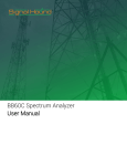
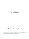
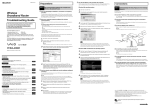
HENRY ENGINEERING
503 Key Vista Drive
Sierra Madre, CA 91024
Tel: 626.355.3656
Fax: 626.355.0077
1.0 DESCRIPTION:
DigiStor II is a multi-message digital audio recorder. It can store up to 8 minutes (16 mins. optional) of monaural
audio with a bandwidth of 6.5 kHz. DigiStor II's multiple modes of use make it ideal for numerous applications in
broadcasting, telecommunications, and commercial sound: network news delay, station or translator ID and spot
insert, message-on-hold, news & actuality lines, call-in telephone information, museum exhibits & displays, sound
effects, announcements, etc. DigiStor II can store up to 8 messages which can be played in any order. Multiple
playback modes support one-time or repeat play, plus automatic sequencing and message "stacking". Messages
can be different lengths, and can be selectively recorded (or changed) without having to re-record other messages.
Messages are stored in non-volatile flash memory and are retained even if power is off. (No backup battery
needed.) Recording and playback is via local or remote control. DigiStor II can record from either a mic or line
level source. Line input and output levels are adjustable. An "eom" relay pulse is automatically generated at the
end of message playback. The included telephone coupler allows DigiStor II to be connected to a phone line for
auto-answer message playback. A special "SR" version adds: "Secondary Cue" relay output, 16 minute storage
time, RS-232 control of Record and Play functions, and front-mounted controls.
2.0 INSTALLATION: DigiStor II can be wall or desk mounted. For desk mounting, install the rubber feet included.
2.1 DC POWER: Connect the included power supply via the POWER terminals. Observe polarity.
2.2 AUDIO INPUTS: DigiStor II can record from either a mic or line level source. To record from a mic, use the
1/8" MIC input jack. This input is unbalanced, and will accept any LO-Z mic signal. To record from a line source
(tape deck, audio mixer, editor) use the RCA LINE input jack. This input is unbalanced, and will accept a line level
signal between about -15 and +4 dBv. The input impedance is 10K ohms; termination is not required. NOTE: The
MIC and LINE inputs cannot be used simultaneously. Use either the MIC OR LINE input, but not both at the same
time.
2.3 AUDIO OUTPUTS: DigiStor II provides two audio outputs: one is at -10 dBm, the other is +4 dBm. Select the
output most appropriate for the equipment being driven. The -10 dBm output is via the RCA jack. This output is
balanced and transformer isolated, and will drive a 600 ohm load. It CAN be ground-referenced if necessary.
The +4 dBm output is via the output terminals labeled SPKR. This is an ACTIVE balanced (transformerless)
output. It can drive any load, including a loudspeaker, with a load impedance of 8 ohms or higher. Because this
output is electronically balanced, DO NOT connect either output terminal to ground. DO NOT reference the load to
ground. It is not necessary to terminate either output.
3.0 DESCRIPTION OF CONTROLS AND LEDs: DigiStor II uses top-mounted pushbuttons for local recording and
playback of messages and to indicate system status. They function as follows:
SWITCHES
RECORD SETUP
Push to enter/exit the Record Setup mode
START/STOP Push to start or stop Play or Record function.
SELECT
Push to select the message to be played or recorded.
LEDs
POWER
ON=Power on, system OK. FLASH=memory error. See Sec. 6.0.
OVERDRIVE ON=Audio input level too high. (Turn Input Level CCW)
AUDIO SENSE ON=Audio input signal present. OFF=No audio detected.
RECORD
FLASH=Ready to record; ON=Recording in process
MESSAGE #s Indicates which message are active or selected, see text below:
The MESSAGE # LEDs indicate the status of each message. When the system is idle, all LEDs are OFF. Each
time the SELECT button is pressed (to select a message for playback), it cycles through active (recorded)
messages, which are indicated with a FLASHING LED. When a message is playing, it's LED will be ON.
When the Record Setup mode is entered, each time the SELECT button is pressed it will show the status of each
Message #. Active (already recorded) messages will have their LEDs FLASH. Empty Message # LEDs will be ON.
During recording the Message # LED will be ON. When recording is stopped, the LED will go OFF.
4.0 OPERATION DigiStor II can be operated by either local or remote control.
4.1 LOCAL OPERATON: How to record and play messages using the pushbuttons on the unit.
4.1.1 RECORDING A MESSAGE (NOTE: The minimum message length is 2 seconds.)
1. Make necessary audio input and output connections to the system. Set OUTPUT LEVEL fully CW.
2. Push the RECORD SETUP button; Record LED will flash.* 3. Press the SELECT button to select the Message
# to be recorded. Message # LEDs will be ON if nothing has been recorded in that location, but will FLASH if there
is already a message recorded.
4. Feed audio into the DigiStor II while watching the AUDIO SENSE and OVERDRIVE LEDs. The AUDIO SENSE
LED should light to confirm audio is present. If the OVERDRIVE LED flashes, the input level it too high. Turn the
INPUT LEVEL control CCW until it goes out. (Audio signal will be heard through the OUTPUT jacks.)
5. Once audio levels have been set, begin recording by pressing the START/STOP button once. The RECORD
and MESSAGE # LEDs will remain ON during recording.
6. To stop recording, press the START/STOP button again. System will return to idle.
* Record Setup will time-out after 1 minute of inactivity.
4.1.2 PLAYING A MESSAGE: (NOTE: CONFIG switches do NOT affect play via pushbuttons on unit.)
1. Press the SELECT button to select Message # to play. SELECT button will only increment between valid
Message #s and the LEDs will flash.*
2. Press the START/STOP button to begin playback. Message # LED will stay ON during playback. 3. Press the
START/STOP button again to stop playback at any time.
* Playback message selection will time-out after 1 minute of inactivity.
4.2 REMOTE OPERATION: How to record and play messages via wired remote control.
4.2.1 REMOTE CONTROL WIRING: DigiStor II remote control connectors must be wired as follows:
There are 2 connectors used for remote control of DigiStor II. Connector #1 (P1) and Connector #2 (P2). P1 is a
12-position pluggable connector used for remote control of Message Play, Stop, and for access to the PLAY
RELAY contacts. P2 is a 3-position connector used for remote control of the Record function. All Play, Stop, and
Record functions are triggered with contact closures to the "COMMON" (ground) pin, P1-1. Pin-outs are detailed
below:
4.2.2 "NORMAL MODE" RECORDING VIA REMOTE CONTROL (CONFIG Switch #3 UP): To record a
message, first activate the RECORD SETUP mode by providing a maintained contact closure between P2-1
(Record) and P1-1 (Common). The RECORD LED will flash. Next, provide a maintained contact closure between
the Message # to be recorded and Common. For example, to record Message #5, provide a maintained closure
between P1-6 and P1-1. Recording will begin; the RECORD and MESSAGE # LEDs will remain ON during
recording. Observe the AUDIO SENSE and OVERDRIVE LEDs to confirm correct audio levels. To stop recording,
release the Message # closure; release the remote Record input closure to exit the recording mode.
4.2.3 "PRIORITY MODE" RECORDING VIA REMOTE CONTROL (CONFIG Switch #3 DOWN): If Priority mode
is selected, DigiStor II will immediately begin recording Message #1 as soon as the remote Record circuit (P2-1) is
connected to Common (P1-1). Recording will terminate when this closure is released. This mode is applicable
when only one message needs to be recorded via remote control, e.g, "network news delay".
4.2.4 PLAYBACK VIA REMOTE CONTROL: To play any message, provide a momentary contact closure
between the desired Message # and Common. For example, to play Message #5, provide a contact closure
between P1-6 and P1-1. NOTE: Some modes of operation require a maintained closure; see section 5.0 for
details about the various playback modes available. During playback, the Message # LED will remain ON. To stop
message playback, provide a momentary contact closure between P1-10 (Stop input) and P1-1 (Common).
4.3 USING DIGISTOR II ON A TELEPHONE LINE: DigiStor II can be used to automatically answer a phone line
and play a message(s) to callers. This mode requires the use of the automatic tele-coupler, included. The telecoupler should be installed as follows:
1. Mate the tele-coupler to the 12-position connector (used for Remote Control Connector #1). The six male pins
on the tele-coupler circuit board should be plugged into terminals 1, 2, 3, 10, 11, and 12 of the 12-position
connector. Unscrew the locking screws for these terminals on the connector, slide the male pins into the connector,
then re-tighten the screws. BE SURE that Pin #1 on the tele-coupler is mated to position #1 on the connector!
Now plug the 12-position terminal block into Connector #1 (P1) on the DigiStor II.
2. Plug the RCA plug that is attached to the tele-coupler into the LINE OUTPUT (RCA) jack on the DigiStor II.
Set the LINE OUTPUT level control fully CW.
3. Connect a standard phone line to the tele-coupler via the modular phone jack.
4. Set the CONFIG switches as follows:
#1, #2: As needed for single-play or repeat play per call. (#1 & #2 UP=Message plays once per call.)
#3, #4, #5, #6, #7: All switches UP.
WARNING! Be sure your phone line is protected against high-voltage 'spikes' and lightning strikes! Use
a surge suppression device to prevent voltage spikes from getting into DigiStor II! High-voltage 'spikes' and
lightning will cause permanent damage to DigiStor II. This damage is NOT covered under your warranty!
Record a message into the DigiStor II using local control. (See Section 4.1.1) BE SURE to record the message
using MESSAGE #1. When the phone line is called, DigiStor II will answer the line a begin playback of the
message. If the caller hangs up during the message, DigiStor II will stop playback, reset the line, and wait for the
next call.
Another possible mode of phone line operation is "rotation play", where DigiStor II plays a different message to
each caller, "in rotation". The first caller would hear Message #1, the next caller would hear Message #2, and so
on. To use this feature, record several messages as usual. Set CONFIG switches as described above, EXCEPT
set CONFIG SWITCH #7 DOWN. The tele-coupler module will need to be modified as follows, see drawing below:
4.4 USING DIGISTOR II FOR MESSAGE-ON-HOLD To use DigiStor II for message-on-hold, record message #1
as usual. Set CONFIG switches #1 & 2 DN, and provide a maintained closure between P1 pins 1 and 2 to start
playback. Do NOT use the tele-coupler. Feed audio from DigiStor II to the "Music-On-Hold" input of phone system.
5.0 SETTING THE CONFIG SWITCHES (NOTE: CONFIG switches affect playback via remote control only.)
DigiStor II has numerous modes of operation that can be programmed with the 8 CONFIG switches. (The switches
are numbered from left to right, 1 through 8.) When DigiStor II is shipped, all CONFIG switches are UP, setting the
unit for normal "default" operation. NOTE: The CONFIG switches are "read" by the system only during power-up.
Changing any CONFIG switches while the system is powered up will have no effect unless the system is shut
down, then powered-up again. (UP=switch is up; DN=switch is down.)
REPEAT MODES: Switches #1 and #2 select the number of times a message plays when triggered, as follows:
#1
#2
UP
UP
Play message 1 time
UP
DN
Play message 2 times
DN
UP
Play message 3 times
DN
DN
Play message 4 times
RECORD MODE:
Switch #3 selects the Record mode.
#3
UP
DN
RELAY MODE:
#4
UP
DN
PLAY MODE:
equals
#6
UP
UP
DN
DN
NORMAL Record mode enabled. See Section 4.2.2 for details.
PRIORITY Record mode enabled. See Section 4.2.3 for details.
Switch #4 selects the operation of the PLAY RELAY, as follows:
PLAY relay stays CLOSED while message is playing.
PLAY relay generates 500ms "EOM" pulse when message stops playing.
Switches #5 and #6 select the playback mode of "message sequences". A "message sequence"
the message audio times the number of plays as selected by CONFIG Switches #1 & #2. #5
UP
DN
UP
DN
Standard operation
See text below for details.
Play one sequence per closure See text below for details.
Play while active
See text below for details.
Re-trigger
See text below for details.
Standard operation: A momentary contact closure causes the system to play one sequence of the message
selected. If the contact closure is maintained, the system will continuously play that sequence until the input is
released, at which time the system will finish the current playback sequence and then stop.
If multiple inputs are held active (maintained closures) the system will play one sequence of the first message, then
cycle through the other messages sequentially, based on the order in which they were activated. This is known as
"message stacking". (Lower message #s will have priority should multiple inputs be activated at exactly the same
time.) Momentary closures will be ignored while any message is playing via a maintained closure.
Play one sequence per closure: If a message input is maintained, the system will only play the message sequence
one time. The system will wait for the input to go inactive for 100ms before it will recognize that input for another
trigger. Other play activations will be serviced normally, even with another input held active indefinitely.
This mode supports "message cueuing". Message cueuing allows the user to input multiple momentary activations
to DigiStor II, causing each message to play in the order it was triggered. The queue length is a maximum of 16
messages. A single message can be queued to play more than once. A STOP command will stop the message
that is currently playing, and when released, the next message in the queue will begin playing. If multiple inputs are
held active (maintained closures), the system will play each message sequence once then stop.
Play while active: Upon receiving a maintained input signal, the message will continue to play for the duration the
input is held active. If the input signal is removed prior to the end of the message sequence, the system will
immediately abort the playback sequence. If the input is sustained after the current playing sequence has
completed, another sequence will begin. If multiple inputs are maintained active, the system will only play the
active message and then repeat. (This mode does not support message queuing.)
Re-trigger: This mode allows playing messages to be interrupted by another incoming message, or another
triggering of the same message. If a message is currently playing and another message trigger is received, the
currently playing message will be terminated and the new message will begin playback. A maintained input will
only play the sequence one time and then stop. If multiple inputs are activated at the same time, only the lower
numbered message will play. (This mode does not support message queuing.)
PLAY NEXT:
Switch #7 enables the Play Next sequential playback mode. If Play Next is ENABLED, only the
Message #8 input is active. Successive momentary closures will play active messages in sequence, from lowest to
highest, then repeat. (This mode can be used with the tele-coupler module for automatic 'rotation' of messages.)
#7
UP
Play Next mode is disabled.
DN
Play Next mode is ENABLED.
NOTE: CONFIG switches will NOT affect operation when messages are played using the local START/STOP
button. CONFIG switches affect play mode only when message playback is triggered via the Remote connector
(P1).
MEMORY PROTECT: Switch #8 allows the user to "lock out" the record mode so that messages cannot be
recorded, erased, or changed.
#8
UP
DN
Normal, message can be recorded
Recording function DISABLED
6.0 MEMORY TEST Use this procedure to clear the system memory of previously recorded messages or to test
and verify the system memory:
1. Remove DC power from DigiStor II.
2. Press and HOLD the RECORD SETUP button while restoring power to the system. Continue to hold the
Record Setup button until the RECORD LED remains ON, then release. The Record LED will remain ON, and the
Message # LEDs will cycle while the system runs an audio memory test. This process could take up to 15 minutes
with standard memory or up to 30 minutes with the 16-minute memory.
3. When Record LED turns OFF, memory test is complete.
4. To abort the memory test, remove then re-apply power.
7.0 ERASING MESSAGES: Individual Message #s can be erased by simply recording a message that is less
than 250ms in length. This short recording will instruct the system to erase the data from that message location.
8.0 TECHNICAL SPECIFICATIONS
Audio Format
12 bit, ADPCM, 16kHz S/R
Frequency Resp
50Hz - 6.5kHz
Sig-to-Noise Ratio
60dB
Dynamic Range
70dB
Distortion
1% @ 1kHz
Mic Input
-50dBm, unbal, 1/8" mini jack, low-Z
Line Input
-10 to +4 dBm, unbal, RCA jack, 10K ohm
Line Output #1
+4dBm, active bal, 600 ohm line or 8 ohm spkr
Line Output #2
-10dBm, xfmr bal, 600 ohm line, RCA jack
Remote Control
Contact closures for Play, Record, Message Select
Relay Output
Either maintained while playing or auto-eom pulse (1A, 24VDC res. load)
Storage Time
8 minutes (Model DS-8); 16 minutes (Model DS-16)
Power requirmnts
12VDC, 500ma. Power supply included
Construction
Steel enclosure, wall or desk mount
Physical
10"W x 8"D x 1.5"H 4 lbs
Approvals
FCC Part 15, Class A (not incl. telecoupler)
UL/CSA on external power supply
Options
Rack mount kit
9.0 WARRANTY
This product is guaranteed against defective material or workmanship for a period of one (1) year from the date of
purchase. Should trouble develop, consult for factory for instructions. If our inspection determines that trouble was
caused by defective material or workmanship, the equipment will be repaired or replaced without charge. Repairs
necessary by abuse, improper use, unauthorized service or maintenance and/or improper installation, as well as
out of warranty repairs will be charged at regular repair prices. The obligation under this warranty shall be limited to
the replacement, repair, or refund of any such defective device within the warranty period, at Henry Engineering's
discretion. This warranty is in lieu of and excludes all other warranties, expressed or implied, and in no event shall
Henry Engineering be responsible for damage to other equipment or property, for any anticipated profits,
consequential damages, loss of item, or other operation or use of this product, and Henry Engineering's maximum
liability shall never be greater than the price paid for this equipment. This warranty does NOT cover defects
resulting from accidents, damage while in transit to factory, alterations, unauthorized repairs, failure to follow
instructions, misuse, fire, flood, and acts of God including but not limited to lightning. This warranty gives you
specific legal rights. Your rights may vary from state to state.
Technical specifications subject to change without notice.
File: DS2BMAN