1
PowerScan® 7000 2D Imager
Product Reference Guide
Datalogic Scanning, Inc.
959 Terry Street
Eugene, Oregon 97402
Telephone: (541) 683-5700
Fax: (541) 345-7140
An Unpublished Work - All rights reserved. No part of the contents of this documentation or the procedures
described therein may be reproduced or transmitted in any form or by any means without prior written permission of Datalogic Scanning, Inc. or its subsidiaries or affiliates ("Datalogic" or “Datalogic Scanning”).
Owners of Datalogic products are hereby granted a non-exclusive, revocable license to reproduce and
transmit this documentation for the purchaser's own internal business purposes. Purchaser shall not
remove or alter any proprietary notices, including copyright notices, contained in this documentation and
shall ensure that all notices appear on any reproductions of the documentation.
Should future revisions of this manual be published, you can acquire printed versions by contacting your
Datalogic representative. Electronic versions may either be downloadable from the Datalogic website
(www.scanning.datalogic.com) or provided on appropriate media. If you visit our website and would like to
make comments or suggestions about this or other Datalogic publications, please let us know via the "Contact Datalogic" page.
Disclaimer
Datalogic has taken reasonable measures to provide information in this manual that is complete and accurate, however, Datalogic reserves the right to change any specification at any time without prior notice.
Datalogic is a registered trademark of Datalogic S.p.A. and the Datalogic logo is a trademark of Datalogic
S.p.A. all licensed to Datalogic Scanning, Inc. All other trademarks and trade names referred to herein are
property of their respective owners.
Patents
This product may be covered by one or more of the following patents: 4603262 • 4639606 • 4652750 • 4672215 • 4699447
• 4709369 • 4749879 • 4786798 • 4792666 • 4794240 • 4798943 • 4799164 • 4820911 • 4845349 • 4861972 • 4861973 •
4866257 • 4868836 • 4879456 • 4939355 • 4939356 • 4943127 • 4963719 • 4971176 • 4971177 • 4991692 • 5001406 •
5015831 • 5019697 • 5019698 • 5086879 • 5115120 • 5144118 • 5146463 • 5179270 • 5198649 • 5200597 • 5202784 •
5208449 • 5210397 • 5212371 • 5212372 • 5214270 • 5229590 • 5231293 • 5232185 • 5233169 • 5235168 • 5237161 •
5237162 • 5239165 • 5247161 • 5256864 • 5258604 • 5258699 • 5260554 • 5274219 • 5296689 • 5298728 • 5311000 •
5327451 • 5329103 • 5330370 • 5347113 • 5347121 • 5371361 • 5382783 • 5386105 • 5389917 • 5410108 • 5420410 •
5422472 • 5426507 • 5438187 • 5440110 • 5440111 • 5446271 • 5446749 • 5448050 • 5463211 • 5475206 • 5475207 •
5479011 • 5481098 • 5491328 • 5493108 • 5504350 • 5508505 • 5512740 • 5541397 • 5552593 • 5557095 • 5563402 •
5565668 • 5576531 • 5581707 • 5594231 • 5594441 • 5598070 • 5602376 • 5608201 • 5608399 • 5612529 • 5629510 •
5635699 • 5641958 • 5646391 • 5661435 • 5664231 • 5666045 • 5671374 • 5675138 • 5682028 • 5686716 • 5696370 •
5703347 • 5705802 • 5714750 • 5717194 • 5723852 • 5750976 • 5767502 • 5770847 • 5786581 • 5786585 • 5787103 •
5789732 • 5796222 • 5804809 • 5814803 • 5814804 • 5821721 • 5822343 • 5825009 • 5834708 • 5834750 • 5837983 •
5837988 • 5852286 • 5864129 • 5869827 • 5874722 • 5883370 • 5905249 • 5907147 • 5923023 • 5925868 • 5929421 •
5945670 • 5959284 • 5962838 • 5979769 • 6000619 • 6006991 • 6012639 • 6016135 • 6024284 • 6041374 • 6042012 •
6045044 • 6047889 • 6047894 • 6056198 • 6065676 • 6069696 • 6073849 • 6073851 • 6094288 • 6112993 • 6129279 •
6129282 • 6134039 • 6142376 • 6152368 • 6152372 • 6155488 • 6166375 • 6169614 • 6173894 • 6176429 • 6188500 •
6189784 • 6213397 • 6223986 • 6230975 • 6230976 • 6237852 • 6244510 • 6259545 • 6260763 • 6266175 • 6273336 •
6276605 • 6279829 • 6290134 • 6290135 • 6293467 • 6303927 • 6311895 • 6318634 • 6328216 • 6332576 • 6332577 •
6343741 • 6454168 • 6478224 • 6568598 • 6578765 • 6705527 • 6974084 • 6991169 •7051940 • AU703547 • D312631 •
D313590 • D320011 • D320012 • D323492 • D330707 • D330708 • D349109 • D350127 • D350735 • D351149 • D351150
• D352936 • D352937 • D352938 • D352939 • D358588 • D361565 • D372234 • D374630 • D374869 • D375493 •
D376357 • D377345 • D377346 • D377347 • D377348 • D388075 • D446524 • EP0256296 • EP0260155 • EP0260156 •
EP0295936 • EP0325469 • EP0349770 • EP0368254 • EP0442215 • EP0498366 • EP0531645 • EP0663643 •
EP0698251 • GB2252333 • GB2284086 • GB2301691 • GB2304954 • GB2307093 • GB2308267 • GB2308678 •
GB2319103 • GB2333163 • GB2343079 • GB2344486 • GB2345568 • GB2354340 • ISR107546 • ISR118507 •
ISR118508 • JP1962823 • JP1971216 • JP2513442 • JP2732459 • JP2829331 • JP2953593 • JP2964278 • MEX185552 •
MEX187245 • RE37166 • Other Patents Pending
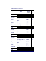
Table of Contents
Chapter 1 Getting Started .........................................................1-1
About This Manual ............................................................................ 1-1
Manual Conventions .................................................................... 1-2
Resetting the Standard Product Defaults .............................................. 1-2
LED and Beeper Indications ............................................................... 1-3
Plug and Play ................................................................................... 1-4
Connecting the imager with an RS-232 Serial Port .......................... 1-4
Connecting the imager with USB ................................................... 1-5
IBM SurePos .............................................................................. 1-6
USB PC Keyboard or USB Macintosh Keyboard ................................ 1-7
USB HID ................................................................................... 1-8
USB COM Port Emulation ............................................................. 1-8
CTS/RTS Emulation ............................................................... 1-8
ACK/NAK Mode ..................................................................... 1-9
Connecting the imager in Universal Keyboard Wedge mode .............. 1-9
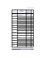
Chapter 2 Terminal Interfaces ..................................................2-1
Terminal ID ..................................................................................... 2-1
Supported Terminals ......................................................................... 2-2
Keyboard Country ............................................................................. 2-3
Keyboard Style ................................................................................. 2-5
Keyboard Modifiers ........................................................................... 2-7
RS-232 Modifiers .............................................................................. 2-8
RS-232 Baud Rate ...................................................................... 2-8
RS-232 Word Length: Data Bits, Stop Bits, and Parity ..................... 2-9
RS-232 Receiver Time-Out ........................................................ 2-10
RS-232 Handshaking ................................................................ 2-11
Chapter 3 Output ......................................................................3-1
Image VGA ...................................................................................... 3-1
Good Read Indicators ........................................................................ 3-1
Beeper – Good Read ................................................................... 3-1
Beeper Volume – Good Read ........................................................ 3-2
Beeper Pitch – Good Read ........................................................... 3-2
Beeper Duration – Good Read ...................................................... 3-3
LED – Good Read ....................................................................... 3-3
Number of Beeps – Good Read ..................................................... 3-3
Good Read Delay .............................................................................. 3-4
User-Specified Good Read Delay ......................................................... 3-4
Trigger Modes .................................................................................. 3-4
Manual/Serial Trigger .................................................................. 3-4
Read Time-Out ..................................................................... 3-5
Manual Trigger, Low Power ..................................................... 3-5
Low Power Time-Out Timer..................................................... 3-5
Product Reference Guide
i
Scan Stand Mode ..............................................................................3-7
Scan Stand Symbol .....................................................................3-7
Presentation Mode .............................................................................3-7
Presentation LED Timer ................................................................3-8
Presentation Sensitivity ...............................................................3-8
Hands Free Time-Out .........................................................................3-8
Double Read Timeout .........................................................................3-9
User-Specified Double Read Timeout ....................................................3-9
LED Power Level ............................................................................. 3-10
Illumination Lights ........................................................................... 3-11
Imager Time-Out ............................................................................ 3-11
Aimer Delay ................................................................................... 3-12
User-Specified Aimer Delay ........................................................ 3-12
Aimer Modes .................................................................................. 3-13
Aimer Mode Off ......................................................................... 3-13
Interlaced Mode ........................................................................ 3-13
Concurrent Mode ...................................................................... 3-13
Centering ....................................................................................... 3-14
Decode Search Mode ....................................................................... 3-16
Output Sequence Overview ............................................................... 3-17
Require Output Sequence ........................................................... 3-17
Output Sequence Editor ............................................................. 3-18
To Add an Output Sequence .................................................. 3-18
Other Programming Selections............................................... 3-19
Output Sequence Examples ........................................................ 3-19
Output Sequence Editor ............................................................. 3-21
Require Output Sequence ........................................................... 3-21
Multiple Symbols ............................................................................. 3-22
No Read ......................................................................................... 3-22
Print Weight ................................................................................... 3-23
Video Reverse ................................................................................. 3-23
Working Orientation ........................................................................ 3-24
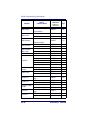
Chapter 4 Data Editing ............................................................. 4-1
Prefix/Suffix Overview .......................................................................4-1
Points to Keep In Mind .................................................................4-2
To Add a Prefix or Suffix: .............................................................4-3
Example: Add a Suffix to a specific symbology...........................4-4
To Clear One or All Prefixes or Suffixes: .........................................4-4
To Add a Carriage Return Suffix to all Symbologies ..........................4-4
Prefix Selections .........................................................................4-5
Suffix Selections .........................................................................4-5
Function Code Transmit ...............................................................4-5
Intercharacter, Interfunction, and Intermessage Delays .........................4-6
Intercharacter Delay ....................................................................4-6
User Specified Intercharacter Delay ...............................................4-7
Interfunction Delay .....................................................................4-7
Intermessage Delay ....................................................................4-8
Chapter 5 Data Formatting....................................................... 5-1
Data Format Editor Introduction ..........................................................5-1
ii
PowerScan® 7000 2D
To Add a Data Format ................................................................. 5-2
Other Programming Selections ..................................................... 5-3
Data Format Editor Commands ..................................................... 5-3
Send Commands ................................................................... 5-3
Move Commands................................................................... 5-4
Search Commands ................................................................ 5-4
Miscellaneous Commands ....................................................... 5-4
Data Format Editor ..................................................................... 5-5
Data Formatter .......................................................................... 5-5
Alternate Data Formats ............................................................... 5-6
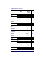
Chapter 6 Symbologies .............................................................6-1
Linear Symbologies ........................................................................... 6-2
All Symbologies .......................................................................... 6-2
Message Length Description.................................................... 6-2
Code 39 ............................................................................... 6-5
Interleaved 2 of 5 ................................................................. 6-9
Code 93 ............................................................................. 6-11
Code 2 of 5 ........................................................................ 6-12
IATA Code 2 of 5................................................................. 6-13
Matrix 2 of 5....................................................................... 6-14
Code 11 ............................................................................. 6-14
Code 128 ........................................................................... 6-16
UPC-A................................................................................ 6-19
UPC-A/EAN-13
with Extended Coupon Code ................................................. 6-21
EAN/JAN-13 ....................................................................... 6-24
EAN/JAN-8 ......................................................................... 6-26
MSI ................................................................................... 6-28
Plessey Code ...................................................................... 6-29
RSS-14 .............................................................................. 6-30
RSS Limited ....................................................................... 6-30
RSS Expanded .................................................................... 6-31
PosiCode ............................................................................ 6-32
Trioptic Code ...................................................................... 6-33
Stacked Symbologies ...................................................................... 6-33
Codablock F........................................................................ 6-33
Code 16K ........................................................................... 6-34
Code 49 ............................................................................. 6-35
PDF417.............................................................................. 6-36
MicroPDF417 ...................................................................... 6-37
EAN•UCC Composite Codes .................................................. 6-37
UPC/EAN Version................................................................. 6-38
TCIF Linked Code 39 (TLC39) ............................................... 6-39
Postal Codes .................................................................................. 6-40
Postnet .............................................................................. 6-40
Planet Code ........................................................................ 6-41
British Post......................................................................... 6-42
Canadian Post..................................................................... 6-42
Kix (Netherlands) Post ......................................................... 6-42
Australian Post.................................................................... 6-43
Japanese Post..................................................................... 6-43
Product Reference Guide
iii
China Post .......................................................................... 6-43
Korea Post .......................................................................... 6-44
QR Code ............................................................................. 6-45
Data Matrix......................................................................... 6-46
MaxiCode............................................................................ 6-47
Aztec Code ......................................................................... 6-48
Chapter 7 Imaging Commands ................................................. 7-1
Image Snap - IMGSNP .......................................................................7-1
IMGSNP Modifiers .......................................................................7-2
Image Ship - IMGSHP ........................................................................7-4
IMGSHP Modifiers .......................................................................7-4
Intelligent Signature Capture - IMGBOX ...............................................7-9
IMGBOX Modifiers ..................................................................... 7-10
Chapter 8 OCR Programming ................................................... 8-1
OCR Fonts ........................................................................................8-2
OCR ..........................................................................................8-2
U.S. Currency Font ......................................................................8-3
MICR E13 B Font .........................................................................8-4
SEMI Font ..................................................................................8-4
OCR Templates .................................................................................8-5
Creating an OCR Template ...........................................................8-5
Template Characters ...................................................................8-6
To Add an OCR Template... .....................................................8-6
Character Match Sequences ....................................................8-7
Adding Spaces.......................................................................8-7
Stringing Together Multiple Formats
(Creating “Or” Statements) .....................................................8-8
OCR User-Defined Variables ................................................................8-9
Reading Multi-Row OCR ...............................................................8-9
OCR Check Character ....................................................................... 8-10
OCR Modulo 10 Check Character ................................................. 8-11
OCR Modulo 36 Check Character ................................................. 8-11
OCR User-Defined Check Character ................................................... 8-12
Programming a User-Defined Check Character .............................. 8-12
Weighting Options ............................................................... 8-13
OCR ISBN Application Example ......................................................... 8-15
OCR Template Codes ....................................................................... 8-16
Exit Selections .......................................................................... 8-17
Chapter 9 Utilities .................................................................... 9-1
To Add a Test Code I.D. Prefix to All Symbologies ..................................9-1
Show Software Revision .....................................................................9-1
Show Data Format ............................................................................9-1
Resetting the Standard Product Defaults ..............................................9-2
Test Menu ........................................................................................9-2
2D PQA (Print Quality Assessment) ......................................................9-2
Power Image Configurator ..................................................................9-3
Power Image Configurator Operations ............................................9-3
Temporary Configuration Using Configurator ...................................9-4
iv
PowerScan® 7000 2D
Installing Power Image Configurator from the Web ......................... 9-4
Chapter 10 Serial Programming Commands............................10-1
Conventions ................................................................................... 10-1
Menu Command Syntax ................................................................... 10-2
Query Commands ..................................................................... 10-2
Tag Field Usage ........................................................................ 10-3
SubTag Field Usage .................................................................. 10-3
Data Field Usage ................................................................. 10-3
Concatenation of Multiple Commands .......................................... 10-3
Responses ............................................................................... 10-3
Examples of Query Commands ................................................... 10-4
Trigger Commands ......................................................................... 10-5
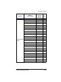
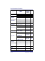
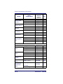
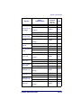
Menu Commands ............................................................................ 10-6
Chapter 11 Product Specifications ..........................................11-1
Imager Product Specifications ..........................................................
Standard Cable Pinouts (Primary Interface Cables) ..............................
Serial Output ..........................................................................
USB ........................................................................................
UKBW .....................................................................................
11-1
11-3
11-3
11-4
11-4
Appendix A Symbologies...........................................................A-1
Symbology Chart .............................................................................. A-1
ASCII Conversion Chart (Code Page 1252) ........................................... A-4
Code Page Mapping of Printed Bar Codes ............................................. A-7
Appendix B Sample Symbols.....................................................B-1
OCR Programming Chart .................................................................... B-4
Programming Chart ........................................................................... B-5
Product Reference Guide
v
vi
PowerScan® 7000 2D
Chapter 1
Getting Started
The PowerScan® 7000 2D imager marks a new performance level for
handheld area imagers. They deliver aggressive read rates and depths of
field on 1D, stacked linear, and matrix codes. This aggressiveness applies
even in challenging reading environments where low lighting conditions
and poor quality might make it difficult to read bar codes. You can rest
assured your investment will continue to supply years of use by reading
any bar codes you require, now or in the future.
Designed for today’s demanding commercial and industrial environments, the scanner offers superior image quality, speed, durability, and
the ability to read poor quality bar codes. The unit is comfortable to
hold, easy to use, rugged, and excellent for the most demanding applications.
About This Manual
This Product Reference Guide (PRG) provides programming instructions for the imager, plus product specifications and dimensions. For
installation, maintenance, troubleshooting and warranty information,
see the Quick Reference Guide (QRG). Copies of other publications for
this product are downloadable free of charge from the website listed on
the back cover of this manual.
The imager is factory programmed for the most common terminal and
communications settings. If you need to change these settings, programming is accomplished by scanning the bar codes in this guide.
An asterisk (*) next to an option indicates the default setting.
Product Reference Guide
1-1
Getting Started
Manual Conventions
The symbols listed below are used in this manual to notify the reader of
key issues or procedures that must be observed when using the imager:
Notes contain information necessary for properly diagnosing, repairing and operating the
imager.
NOTE
The CAUTION symbol advises you of actions
that could damage equipment or property.
CAUTION
Resetting the Standard Product
Defaults
If you aren’t sure what programming options are in your imager, or
you’ve changed some options and want the factory settings restored, scan
the Standard Product Default Settings bar code below.
Standard Product Default Settings
The chart Menu Commands, starting on page 10-6 lists the factory default
settings for each of the menu commands (indicated by an asterisk (*) on
the following programming pages.
1-2
PowerScan® 7000 2D
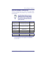
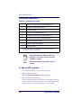
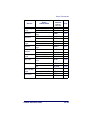
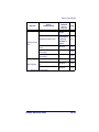
LED and Beeper Indications
LED and Beeper Indications
The imager is equipped with a beeper (speaker) and two indicator LEDs;
one green and one yellow. These indicators “beep” or flash when certain
actions take place:
NOTE
Some LED and Beeper indications are user-configurable for volume, pitch, quantity, duration,
enable/disable, etc. Those listed in the following
table assume the feature is enabled. See the
Product Reference Guide (PRG) for detailed programming information.
Condition
Powering On
UKBW/RS-232 Models
(using UKBW interface)
Powering On
UKBW/RS-232 Models
(using RS-232 interface)
Powering On
All Other Models
Good Read
Error Indication
Green LED
Beeper
2 normal flashes and 2 fast flashes
(+ 1 normal flash with Smart cable)
One Beep
2 normal flashes and 1 long flash
One Beep
Bright Green Flash
One Beep
1 - 9 Bright Green Flash(es)a
Green Flash
1 - 9 Beep(s)a
Yellow LED
Beeper
Yellow LED on steady until trigger is pulled
None
Condition
Ready to Operate
Special Beep
a. Good Read indications are synchronous. That is, if Good Read beeps
are set via programming to five (for example), the Good Read LED will
also flash five times.
Product Reference Guide
1-3
Getting Started
Plug and Play
Plug and Play bar codes provide instant imager set up for commonly
used interfaces.
After you scan one of the codes, power cycle
the host terminal to have the interface in effect.
NOTE
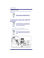
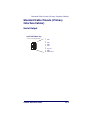
Connecting the imager with an RS-232
Serial Port
These instructions are for use with the RS-232
cable. This includes both Power Off the Terminal (P.O.T.) and external power.
NOTE
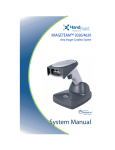
1. Turn off power to the terminal/computer.
2. Connect the appropriate interface cable to the imager.
For the imager to work properly, you must have
the correct cable for your type of terminal/computer.
NOTE
Cable Connector
Retainer Boss
Captive
Screws
1-4
For 220-230 VAC
adapters, the
cord must be
facing down as
shown in the
illustration. If
installed upwards,
it will pose an
undue strain on the
socket outlet.
PowerScan® 7000 2D
Plug and Play
3. Plug the serial connector into the serial port on your computer.
Tighten the two screws to secure the connector to the port.
4. If the terminal does not support Power Off the Terminal (P.O.T.)
connections plug the power supply into the host connector and the
AC outlet.
5. Once the imager has been fully connected, power up the computer.
All communication parameters between the imager and terminal must
match for correct data transfer through the serial port using RS-232 protocol. Scanning the RS-232 interface bar code, programs the imager for
an RS-232 interface at 115,200 baud, parity–none, 8 data bits, 1 stop
bit, and adds a suffix of a CR LF.
RS-232 Interface
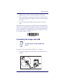
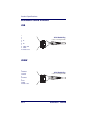
Connecting the imager with USB
This interface applies to USB compatible models only.
NOTE
An imager can be connected to the USB port of a computer.
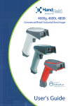
1. Connect the appropriate interface cable to the imager and to the
computer.
Captive
Screws
B
Cable Connector
Retainer Boss
US
Product Reference Guide
1-5
Getting Started
2. The imager beeps.
3. Verify imager operation by scanning the part number bar code
from the back cover of this manual.
NOTE
The following USB “Plug and Play” codes are
supported on specific models. Refer to the
Product Reference Guide to determine if this
interface applies to your unit.
For additional USB programming and technical information, visit the
website listed on the back cover of this manual.
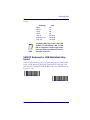
IBM SurePos
Scan one of the following “Plug and Play” codes to program the imager
for IBM SurePos (USB Hand Held imager) or IBM SurePos (USB
Tabletop imager).
After scanning one of these codes, you must
power cycle the cash register
NOTE
IBM SurePos
(USB Hand Held imager) Interface
IBM SurePos
(USB Tabletop imager) Interface
1-6
PowerScan® 7000 2D
Plug and Play
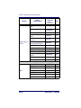
Each bar code above also programs the following suffixes for each symbology:
Symbology
EAN-8
EAN-13
UPC-A
UPC-E
Code 39
Interleaved 2 of 5
Code 128
NOTE
Suffix
0C
16
0D
0A
00 0A 0B
00 0D 0B
00 18 0B
The following USB “Plug and Play” codes (USB
Keyboard - PC, USB Keyboard - Mac, and USB
HID) are supported on specific imager models.
Check your model type to determine if this interface applies to your unit.
USB PC Keyboard or USB Macintosh Keyboard
Scan one of the following codes to program the imager for USB PC Keyboard or USB Macintosh Keyboard. Scanning these codes adds a CR
and selects the terminal ID (USB PC Keyboard - 124, USB Macintosh
Keyboard - 125).
USB Keyboard (PC)
USB Keyboard (Mac)
Product Reference Guide
1-7
Getting Started
USB HID
Scan the following code to program the imager for USB HID bar code
imagers. Scanning this code changes the terminal ID to 131.
USB HID Bar Code imager
USB COM Port Emulation
Scan the following code to program the imager to emulate a regular RS232-based COM port. If you are using a Microsoft® Windows® PC,
you will need to download a driver from the website listed on the back
cover of this manual. The driver will use the next available COM port
number. Apple® Macintosh computers recognize the imager as a USB
CDC class device and automatically use a class driver. Scanning the code
below changes the terminal ID to 130.
USB COM Port Emulation
No extra configuration (e.g., baud rate) is necessary.
NOTE
CTS/RTS Emulation
On
* Off
1-8
PowerScan® 7000 2D
Plug and Play
ACK/NAK Mode
On
* Off
Reference the Product Reference Guide (PRG) for
more information about keyboard support.
NOTE
Connecting the imager in Universal Keyboard Wedge mode
The Universal Keyboard Wedge (UKBW) model allows an RS-232
transmission or Keyboard Wedge mode according to the type of cable
connected. Contact Datalogic or your dealer for cable and/or power supply part numbers.
1. Turn off power to the terminal/computer.
2. Connect the keyboard wedge interface cable to the imager.
For the imager to work properly, you must have
the correct cable for your type of terminal/computer.
NOTE
Product Reference Guide
1-9
Getting Started
3. Connect one end of the Y cable to the keyboard cable and the
other to the keyboard port on the host/computer.
Cable Connector
Retainer Boss
K ey
bo
ard
Captive
Screws
4. Scan the following bar code to program the imager for the UKBW
interface.
~ p Universal
a p 2 Keyboard
3 2 ; Wedge
2 3 (UKBW)
2 C T Interface
S 1 ³
1-10
.
PowerScan® 7000 2D
Chapter 2
Terminal Interfaces
Use this section to configure interface features
for imager models using RS-232 and USB interfaces.
NOTE
For Imager models using UKBW interfaces, do
not use this section but refer to the UKBW Connectivity Guide available for download from the
website listed on the back over of this manual.
In most cases and mainly in Concurrent Aiming
mode an external power supply is required.
Terminal ID
If your interface is not a standard PC AT, refer to Supported Terminals on
page 2-2, and locate the Terminal ID number for your PC. Scan the Terminal ID bar code below, then scan the numeric bar code(s) on the Programming Chart on page B-5 of this manual to program the Imager for
your terminal ID. Scan Save to save your selection.
Product Reference Guide
2-1
Terminal Interfaces
For example, an IBM AT terminal has a Terminal ID of 003. You would
scan the Terminal ID bar code, then 0, 0, 3 from the Programming Chart on
page B-5 of this manual, then Save. If you make an error while scanning
the digits (before scanning Save), scan the Discard code marked Discard
on page B-4, scan the Terminal ID bar code, scan the digits, and the Save
code again.
Terminal ID
Save
After scanning one of these codes, you must
power cycle your computer.
NOTE
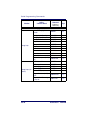
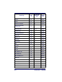
Supported Terminals
Terminal
IBM SurePOS
IBM SurePOS
RS-232 True
RS-232 TTL
Serial Wedge
USB COM Port Emulation
USB PC Keyboard
USB Mac Keyboard
USB HID POS
Model(s)
USB Hand Held Imager
USB Tabletop Imager
Terminal ID
128a
129a
000b
000
050
130a
124a
125a
131a
a. Applies to USB models only. It is best to use the Plug and Play bar
codes located in the Quick Reference Guide, to program these interfaces, rather than scanning the terminal ID listed in this table.
b. Default for RS-232 models
2-2
PowerScan® 7000 2D
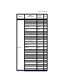
Keyboard Country
Keyboard Country
Scan the appropriate country code below to program the keyboard for
your country. As a general rule, the following characters are supported,
but need special care for countries other than the United States:
@ | $ # { } [ ] = / ‘ \ < > ~
* United States
Belgium
Brazil
Canada (French)
Czechoslovakia
Denmark
Finland (Sweden)
France
Germany/Austria
Greece
Hungary
Israel (Hebrew)
Product Reference Guide
2-3
Terminal Interfaces
Keyboard Country (continued)
Italy
Latin America
Netherlands (Dutch)
Norway
Poland
Portugal
Romania
Russia
SCS
Slovakia
Spain
Sweden
Switzerland (German)
2-4
PowerScan® 7000 2D
Keyboard Style
Keyboard Country (continued)
Turkey F
Turkey Q
U.K.
Keyboard Style
This programs keyboard styles, such as Caps Lock and Shift Lock.
Default = Regular.
Regular is used when you normally have the Caps Lock key off.
* Regular
Caps Lock is used when you normally have the Caps Lock key on.
Caps Lock
Shift Lock is used when you normally have the Shift Lock key on (not
common to U.S. keyboards).
Shift Lock
Product Reference Guide
2-5
Terminal Interfaces
Automatic Caps Lock is used if you change the Caps Lock key on and off.
The software tracks and reflects if you have Caps Lock on or off (AT and
PS/2 only). This selection can only be used with systems that have an
LED which notes the Caps Lock status.
Automatic Caps Lock
Autocaps via NumLock bar code should be scanned in countries (e.g.,
Germany, France) where the Caps Lock key cannot be used to toggle
Caps Lock. The NumLock option works similarly to the regular Auotcaps, but uses the NumLock key to retrieve the current state of the Caps
Lock.
Autocaps via NumLock
Emulate External Keyboard should be scanned if you do not have an
external keyboard (IBM AT or equivalent).
Emulate External Keyboard
After scanning the Emulate External Keyboard
bar code, you must power cycle your computer.
NOTE
2-6
PowerScan® 7000 2D
Keyboard Modifiers
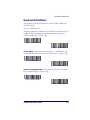
Keyboard Modifiers
This modifies special keyboard features, such as CTRL+ ASCII codes
and Turbo Mode.
Control + ASCII Mode On
The Imager sends key combinations for ASCII control characters for values 00-1F. Refer to Keyboard Function Relationships on page 9-1 for
CTRL+ ASCII Values. Default = Off
Control + ASCII Mode On
* Control + ASCII Mode Off
Turbo Mode— The imager sends characters to a terminal faster. If
the terminal drops characters, do not use Turbo Mode. Default = Off
Turbo Mode On
* Turbo Mode Off
Numeric Keypad Mode— Sends numeric characters as if entered
from a numeric keypad. Default = Off
Numeric Keypad Mode On
* Numeric Keypad Mode Off
Product Reference Guide
2-7
Terminal Interfaces
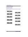
RS-232 Modifiers
RS-232 Baud Rate
Baud Rate sends the data from the imager to the terminal at the specified
rate. The host terminal must be set for the same baud rate as the imager.
Default = 115,200.
300
600
1200
2400
4800
9600
19200
38400
57,600
*115,200
2-8
PowerScan® 7000 2D
RS-232 Modifiers
RS-232 Word Length: Data Bits, Stop Bits,
and Parity
Data Bits sets the word length at 7 or 8 bits of data per character. If an
application requires only ASCII Hex characters 0 through 7F decimal
(text, digits, and punctuation), select 7 data bits. For applications which
require use of the full ASCII set, select 8 data bits per character. Default
= 8.
Stop Bits sets the stop bits at 1 or 2. Default = 1.
Parity provides a means of checking character bit patterns for validity.
Default = None.
7 Data, 1 Stop, Parity Even
7 Data, 1 Stop, Parity None
7 Data, 1 Stop, Parity Odd
7 Data, 2 Stop, Parity Even
7 Data, 2 Stop Parity None
7 Data, 2 Stop, Parity Odd
8 Data, 1 Stop, Parity Even
* 8 Data, 1 Stop, Parity None
8 Data, 1 Stop, Parity Odd
Product Reference Guide
2-9
Terminal Interfaces
RS-232 Receiver Time-Out
The unit stays awake to receive data until the RS-232 Receiver TimeOut expires. A manual or serial trigger resets the time-out. When an
RS-232 receiver is sleeping, a character may be sent to wake up the
receiver and reset the time-out. A transaction on the CTS line will also
wake up the receiver. The receiver takes 300 milliseconds to completely
come up. Change the RS-232 receiver time-out by scanning the bar
code below, then scanning digits from the Programming Chart on page B5 of this manual, then scanning Save. The range is 0 to 300 seconds.
Default = 0 seconds (no time-out - always on).
RS-232 Receiver Time-Out
2-10
PowerScan® 7000 2D
RS-232 Modifiers
RS-232 Handshaking
RS-232 handshaking is a set of rules concerning the exchange of data
between serially communicating devices.
If using RTS/CTS handshaking, the imager issues an active RTS signal
to the receiving device. The imager waits to send its data until it detects
an active CTS signal from the receiving device. The imager then sends
its data while checking the CTS signal before the transmission of each
data character. If an inactive CTS signal is detected at any time, the
imager halts transmission until it detects another active CTS signal.
When the imager has finished transmitting data, it issues an inactive
RTS signal to the receiving device. Default = RTS/CTS Off, XON/XOFF
Off, and ACK/NAK Off.
RTS/CTS On
* RTS/CTS Off
XON/XOFF On
* XON/OFF Off
ACK/NAK On
* ACK/NAK Off
Product Reference Guide
2-11
Terminal Interfaces
NOTES
2-12
PowerScan® 7000 2D
Chapter 3
Output
Image VGA
You can set the image size to a VGA resolution, if necessary, to accommodate older applications that require a smaller image size. When Image
VGA is set to On, the resultant image is 640x480 pixels. When Image
VGA is Off, your image is 752x480 pixels. Default = Off.
* Off
On
Good Read Indicators
Beeper – Good Read
The beeper may be programmed On or Off in response to a good read.
Turning this option off, only turns off the beeper response to a good read
indication. All error and menu beeps are still audible. Default = On.
* On
Off
Product Reference Guide
3-1
Output
Beeper Volume – Good Read
The beeper volume codes modify the volume of the beep the imager
emits on a good read. Default = Medium.
Low
* Medium
High
Off
Beeper Pitch – Good Read
The beeper pitch codes modify the pitch (frequency) of the beep the
imager emits on a good read. Default = Medium.
Low (1400 Hz)
Medium (2800 Hz)
* High (3100 Hz)
3-2
PowerScan® 7000 2D
Good Read Indicators
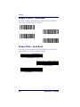
Beeper Duration – Good Read
The beeper duration codes modify the length of the beep the imager
emits on a good read. Default = Normal.
* Normal Beep
Short Beep
LED – Good Read
The LED indicator can be programmed On or Off in response to a good
read. Default = On.
* On
Off
Number of Beeps – Good Read
The number of beeps of a good read can be programmed from 1 - 9.
The same number of beeps will be applied to the beeper and LED in
response to a good read. For example, if you program this option to have
five beeps, there will be five beeps and five LED flashes in response to a
good read. The beeps and LED flashes are in sync with one another. To
change the number of beeps, scan the bar code below and then scan a
digit (1-9) bar code and the Save bar code on the Programming Chart on
page B-5 of this manual. Default = One.
Number of Pulses
Product Reference Guide
3-3
Output
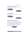
Good Read Delay
This sets the minimum amount of time before the imager can read
another bar code. Default = No Delay.
* No Delay
Short Delay (500 ms)
Medium Delay (1,000 ms)
Long Delay (1,500 ms)
User-Specified Good Read Delay
If you want to set your own length for the good read delay, scan the bar
code below, then set the delay (from 0-30,000 milliseconds) by scanning
digits from the Programming Chart on page B-5, then scanning Save.
User-Specified Good Read Delay
Trigger Modes
Manual/Serial Trigger
You can activate the imager either by pressing the trigger, or using a serial
trigger command (see Trigger Commands on page 10-5). When in manual trigger mode, the imager scans until a bar code is read, or until the
trigger is released.
3-4
PowerScan® 7000 2D
Trigger Modes
When in serial mode, the imager scans until a bar code has been read or
until the deactivate command is sent. In serial mode, the imager can also
be set to turn itself off after a specified time has elapsed (see Read TimeOut, which follows).
* Manual/Serial Trigger
Read Time-Out
Use this selection to set a time-out (in milliseconds) of the imager’s trigger when using serial commands to trigger the imager, or if the imager is
in manual trigger mode. Once the imager has timed out, you can activate the imager either by pressing the trigger or using a serial trigger
command. After scanning the Read Time-Out bar code, set the time-out
duration (from 0-300,000 milliseconds) by scanning digits from the Programming Chart on page B-5, then scanning Save. Default = 0 (infinite,
or no time-out).
Read Time-Out
Manual Trigger, Low Power
The imager powers down until the trigger is pulled. When the trigger is
pulled, the imager powers up and operates until there is no triggering for
the time set with the Low Power Time-Out bar code below. There is a
delay of up to one second in operation when the imager is first triggered,
but there is no delay when operating in low power time-out mode.
Manual Trigger, Low Power
Low Power Time-Out Timer
Scan the Low Power Time-Out bar code to change the time-out duration (in seconds). Then scan the time-out duration (from 0-300 seconds) from the Programming Chart on page B-5, and Save. Default =
120 seconds.
Product Reference Guide
3-5
Output
If the unit remains idle during the low power time-out interval, the unit
goes into low power mode. Whenever the trigger is enabled, the low
power time-out timer is reset.
Low Power Time-Out
This time-out does not begin until the imager
time-out setting has expired.
NOTE
3-6
PowerScan® 7000 2D
Scan Stand Mode
Scan Stand Mode
When a unit is in Scan Stand mode, it remains idle as long as it sees the
Scan Stand symbol. (See Scan Stand Symbol that follows.) When a different code is presented, the Imager is triggered to read the new code.
Note:The imager automatically adjusts the illumination LEDs to the
lowest light level possible to maintain a good lock on the Scan Stand
symbol. When a symbol is presented, the imager’s light levels adjust to
the saved setting (see LED Power Level on page 3-10).
Scan Stand Mode
Scan Stand Symbol
When a unit is in Scan Stand mode, the LEDs shine at the Scan Stand
symbol on the base of the stand which tells it to remain idle. When the
Scan Stand symbol is covered, the imager turns the LEDs on at the configured power level (Default High) and attempts to find and decode bar
codes in its field of view.
Scan Stand Symbol
Presentation Mode
This programs the imager to work in Presentation Mode.
Presentation Mode
Product Reference Guide
3-7
Output
Presentation LED Timer
When an imager is in presentation mode, the LEDs turn off immediately
after a bar code is decoded. The imager can be programmed to continue
scanning and to keep the LEDs on for a short time after by scanning the
LEDs On bar code below. Default = LEDs On.
* LEDs On
LEDs Off
Presentation Sensitivity
Presentation Sensitivity is a numeric range that increases or decreases the
imager's reaction time to bar code presentation. To set the sensitivity,
scan the Sensitivity bar code, then scan the degree of sensitivity (from 020) from the Programming Chart on page B-5, and Save. 0 is the most
sensitive setting, and 20 is the least sensitive. Default = 1.
Sensitivity
Hands Free Time-Out
The Scan Stand and Presentation Modes are referred to as “hands free”
modes. If the imager’s trigger is pulled when using a hands free mode,
the imager changes to manual trigger mode. You can set the time the
imager should remain in manual trigger mode by setting the Hands Free
Time-Out. Once the time-out value is reached, (if there have been no
further trigger pulls) the imager reverts to the original hands free mode.
3-8
PowerScan® 7000 2D
Double Read Timeout
Scan the Hands Free Time-Out bar code, then scan the time-out duration
(from 0-300,000 milliseconds) from the Programming Chart on page B-5,
and Save. Default = 5,000 ms.
Hands Free Time-Out
Double Read Timeout
This sets the time period before the imager can read the same bar code a
second time. Setting a reread delay protects against accidental rereads of
the same bar code. Longer delays are effective in minimizing accidental
rereads at POS (point of sale). Use shorter delays in applications where
repetitive bar code scanning is required. Default = Medium.
Reread Delay only works when in Presentation Mode (see Presentation
Mode on page 3-7).
Short (500 ms)
* Medium (750 ms)
Long (1000 ms)
Extra Long (2000 ms)
User-Specified Double Read Timeout
If you want to set your own length for the reread delay, scan the bar code
below, then set the delay (from 0-30,000 milliseconds) by scanning digits from the Programming Chart on page B-5, then scanning Save.
User-Specified Double Read Timeout
Product Reference Guide
3-9
Output
LED Power Level
This selection allows you to adjust LED and aimer brightness. Off is
used when no illumination is needed. Low is used if low illumination is
sufficient. High (the default) is the brightest setting.
If you have an aimer delay programmed (see Aimer Delay on page 3-12),
the aimer will be at 100% power during the delay, regardless of the LED
Power Level.
NOTE
If you scan the Off bar code, both the aimer and
illumination lights turn off, making it impossible
to scan bar codes in low light. To turn the LED
Power Level back on, move to a brightly lit area
and scan either the Low or the High bar code
below.
Off
Low (50%)
* High (100%)
3-10
PowerScan® 7000 2D
Illumination Lights
Illumination Lights
If you want the illumination lights on while reading a bar code, scan the
Lights On bar code, below. However, if you want to turn just the lights
off, scan the Lights Off bar code.
This setting does not affect the aimer light. The
aiming light can be set using Aimer Mode (see
Aimer Modes on page 3-13).
NOTE
* Lights On
Lights Off
Imager Time-Out
Imager Time-Out powers down the imager after the unit has been idle
for the specified time. To prevent the imager from powering down, set
this time-out to 0. Scan the bar code below, then set the time-out by
scanning digits (from 0 - 999,999 ms) from the Programming Chart on
page B-5, then scanning Save. Default = 120,000 ms.
Imager Time-Out
Product Reference Guide
3-11
Output
Aimer Delay
The aimer delay allows a delay time for the operator to aim the imager
before the picture is taken. Use these codes to set the time between when
the trigger is pulled and when the picture is taken. During the delay
time, the aiming light will appear, but the LEDs won’t turn on until the
delay time is over.
200 milliseconds
400 milliseconds
* Off (no delay)
User-Specified Aimer Delay
If you want to set your own length for the duration of the delay, scan the
bar code below, then set the time-out by scanning digits (0 - 4,000 ms)
from the Programming Chart on page B-5 of this manual, then scan Save.
Delay Duration
3-12
PowerScan® 7000 2D
Aimer Modes
Aimer Modes
This feature allows you to select from the three options listed below:
Aimer Mode Off
Aimer Mode is disabled.
Interlaced Mode
In Interlaced Mode, the illumination and aiming timing is automatically
synchronized to the imager exposure period by the Optics Module. The
module turns illumination on while the image is being exposed, and it
turns the aiming off at all other times. Interlaced Mode provides the lowest overall current draw and is recommended for most applications. It
also provides the brightest aimer in most applications. Imager software
automatically maintains an approximate 25% aimer duty cycle, even
when the imager exposure time is at its maximum in dark operating
environments.
NOTE
When in Interlaced Mode, the illumination level
will dynamically change with the degree of
ambient light and reflection from the bar code
being scanned.
Concurrent Mode
Concurrent Mode is provided for backwards
compatibility with previous models, and is not
recommended for most applications.
NOTE
In Concurrent Mode, the illumination LEDs are on continuously, while
the aimer LEDs turn off during the imager exposure period, and on
while the imager is not exposing. This Mode is used to eliminate any
flicker of the illumination LEDs that may be objectionable to the user.
In Concurrent Mode, the illumination LED current is reduced in comparison to Interlaced Mode with regard to limiting engine peak current.
Imager software automatically maintains an approximate 25% aimer
Product Reference Guide
3-13
Output
duty cycle, even when the imager exposure time is at its maximum in
dark operating environments.
Concurrent mode provides the brightest appearance of the illumination
LEDs of any of the imager operating modes. This mode may be useful
for applications when an operator is using the illumination LEDs for
aiming, such as in fixed mount, kiosk, or auto trigger applications.
Off
* Concurrent
Interlaced
Centering
Use Centering to narrow the imager’s field of view to make sure the
imager reads only those bar codes intended by the user. For instance, if
multiple codes are placed closely together, centering will insure that only
the desired codes are read. (Centering can be used in conjunction with
Aimer Delay on page 3-12, for the most error-free operation in applications where multiple codes are spaced closely together. Using the Aimer
Delay and Centering features, the imager can emulate the operation of
older systems, such as linear laser bar code imagers.)
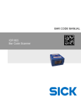
Figure 3-1. Centering Example
Bar Code 1
Bar Code 2
3-14
PowerScan® 7000 2D
Centering
In the example in Figure 3-1, the gray area is the full imager field of view
and the white area is the centering window. Bar Code 1 will not be read,
while Bar Code 2 will be.The default centering window is a 128x96 pixel
area in the center of the imager’s field of view. The following diagram
illustrates the default top, bottom, left, and right pixel positions, measured from the top and the left side of the imager’s field of view, which is
640 by 480 pixels.
40%
60%
100%
0
Top
40%
Bottom
Default
Center
60%
Left
Right
100%
If a bar code is not within the predefined window, it will not be decoded
or output by the imager. If centering is turned on by scanning Centering
On, the imager only reads codes that intersect the centering window you
specify using the Top, Bottom, Left, or Right bar codes.
Product Reference Guide
3-15
Output
Scan Centering On, then scan one of the following bar codes to change
the top, bottom, left, or right of the centering window. Then scan the
percent you want to shift the centering window using digits on the Programming Chart on page B-5. Scan Save. Default Centering = 40% for
Top and Left, 60% for Bottom and Right.
Centering On
* Centering Off
Top of Centering Window
Bottom of Centering Window
Left of Centering Window
Right of Centering Window
Decode Search Mode
There are three selectable decode (scanning) modes:
Full Omnidirectional - Searches for bar code features beginning at the
center of an image, and searches to the image’s limits. This mode reads
all symbologies (including OCR), in any orientation. The Full Omnidirectional search is very thorough which may slow performance time.
This search mode is the default setting.
NOTE
Full Omnidirectional
3-16
PowerScan® 7000 2D
Output Sequence Overview
Quick Omnidirectional - This is an abbreviated search for bar code features around the center region of an image. This mode quickly reads all
symbologies in any orientation. The Quick Omnidirectional mode may
miss some off-center symbols, as well as larger Data Matrix and QR
Code symbols.
Quick Omnidirectional
Advanced Linear Decoding - Performs quick horizontal linear scans in a
center band of the image. This mode is not omnidirectional, but does
quickly read linear and stacked bar codes. Advanced Linear Decoding
cannot read 2D, OCR, or Postal symbols.
This search mode is the default setting for point-and-shoot PDF imagers.
Advanced Linear Decoding
Output Sequence Overview
Require Output Sequence
When turned off, the bar code data will be output to the host as the
Imager decodes it. When turned on, all output data must conform to an
edited sequence or the Imager will not transmit the output data to the
host device.
This selection is unavailable when the Multiple
Symbols Selection is turned on.
NOTE
Product Reference Guide
3-17
Output
Output Sequence Editor
This programming selection allows you to program the Imager to output
data (when scanning more than one symbol) in whatever order your
application requires, regardless of the order in which the bar codes are
scanned. Reading the Default Sequence symbol programs the Imager to
the Universal values, shown below. These are the defaults. Be certain
you want to delete or clear all formats before you read the Default
Sequence symbol.
NOTE
To make Output Sequence Editor selections,
you’ll need to know the code I.D., code length,
and character match(es) your application
requires. Use the Alphanumeric symbols from
the Programming Chart on page B-5 to read
these options.
To Add an Output Sequence
1. Scan the Enter Sequence symbol (see Multiple Symbols on page 322).
2. Code I.D.
On the Symbology Chart on page A-1, find the symbology to which
you want to apply the output sequence format. Locate the Hex
value for that symbology and scan the 2 digit hex value from the
Programming Chart on page B-5.
3. Length
Specify what length (up to 9999 characters) of data output will be
acceptable for this symbology. Scan the four digit data length from
the Programming Chart. (Note: 50 characters is entered as 0050.
9999 is a universal number, indicating all lengths.) When calculating the length, you must count any programmed prefixes, suffixes,
or formatted characters as part of the length (unless using 9999).
4. Character Match Sequences
From the ASCII Conversion Chart (Code Page 1252) on page A-4,
find the Hex value that represents the character(s) you want to
match. Use the Programming Chart to read the alphanumeric
combination that represents the ASCII characters. (99 is the Universal number, indicating all characters.)
3-18
PowerScan® 7000 2D
Output Sequence Overview
5. End Output Sequence Editor
Scan F F to enter an Output Sequence for an additional symbology, or Save to save your entries.
Other Programming Selections
Discard
This exits without saving any Output Sequence changes.
Output Sequence Examples
In this example, you are scanning Code 93, Code 128, and Code 39 bar
codes, but you want the imager to output Code 39 1st, Code 128 2nd,
and Code 93 3rd, as shown below.
Code 93 must be enabled to use this example.
NOTE
A - Code 39
B - Code 128
C - Code 93
You would set up the sequence editor with the following command line:
SEQBLK62999941FF6A999942FF69999943FF
Product Reference Guide
3-19
Output
The breakdown of the command line is shown below:
SEQBLK
62
9999
41
FF
6A
9999
42
FF
69
9999
43
FF
sequence editor start command
code identifier for Code 39
code length that must match for Code 39, 9999 = all lengths
start character match for Code 39, 41h = “A”
termination string for first code
code identifier for Code 128
code length that must match for Code 128, 9999 = all lengths
start character match for Code 128, 42h = “B”
termination string for second code
code identifier for Code 93
code length that must match for Code 93, 9999 = all lengths
start character match for Code 93, 43h = “C”
termination string for third code
To program the previous example using specific lengths, you would have
to count any programmed prefixes, suffixes, or formatted characters as
part of the length. If you use the example on page 3-19, but assume a
<CR> suffix and specific code lengths, you would use the following command line:
SEQBLK62001141FF6A001242FF69001143FF
The breakdown of the command line is shown below:
SEQBLK
62
0011
41
FF
6A
0012
42
FF
69
0011
43
FF
3-20
sequence editor start command
code identifier for Code 39
Code 39 code length (9) plus CR suffix (2) = 11
start character match for Code 39, 41h = “A”
termination string for first code
code identifier for Code 128
Code 128 code length (10) plus CR suffix (2) = 12
start character match for Code 128, 42h = “B”
termination string for second code
code identifier for Code 93
Code 93 code length (9) plus CR suffix (2) = 11
start character match for Code 93, 43h = “C”
termination string for third code
PowerScan® 7000 2D
Output Sequence Overview
Output Sequence Editor
Enter Sequence
Default Sequence
Require Output Sequence
When an output sequence is Required, all output data must conform to
an edited sequence or the imager will not transmit the output data to the
host device. When it’s On/Not Required, the imager will attempt to get
the output data to conform to an edited sequence, but if it cannot, the
imager transmits all output data to the host device as is.
When the output sequence is Off, the bar code data is output to the host
as the imager decodes it.
This selection is unavailable when the Multiple
Symbols Selection is turned on.
NOTE
Required
On/Not Required
*Off
Product Reference Guide
3-21
Output
Multiple Symbols
This feature does not work when the Imager is
in Low Power mode.
NOTE
When this programming selection is turned On, it allows you to read
multiple symbols with a single pull of the Imager’s trigger. If you press
and hold the trigger, aiming the Imager at a series of symbols, it reads
unique symbols once, beeping (if turned on) for each read. The imager
attempts to find and decode new symbols as long as the trigger is pulled.
When this programming selection is turned Off, the Imager will only
read the symbol closest to the aiming beam.
On
* Off
No Read
With No Read turned On, the Imager notifies you if a code cannot be
read. If using a PowerView Scan Data Window, an “NR” appears when
a code cannot be read. If No Read is turned Off, the “NR” will not
appear.
On
* Off
If you want a different notation than “NR,” for example, “Error,” or
“Bad Code,” you can edit the output message using the Data Formatter
on page 5-5. The hex code for the No Read symbol is 9C.
3-22
PowerScan® 7000 2D
Print Weight
Print Weight
Print Weight is used to adjust the way the imager reads Matrix symbols.
If a imager will be seeing consistently heavily printed matrix symbols,
then a print weight of 6 may improve the reading performance. For consistently light printing, a print weight of 2 may help. After scanning the
Set Print Weight bar code, set the print weight (from 1-7) by scanning
digits from the Programming Chart on page B-5, then scanning Save.
Default = 4.
Set Print Weight
* Default
Video Reverse
Video Reverse is used to allow the imager to read bar codes that are
inverted. The “Off ” bar code below is an example of this type of bar
code. If additional menuing is required, Video Reverse must be disabled
to read the menu bar codes and then re-enabled after menuing is completed.
Images downloaded from the unit will not be
reversed. This is a setting for decoding only.
NOTE
On
* Off
Product Reference Guide
3-23
Output
Working Orientation
Some bar codes are direction-sensitive. For example, KIX codes and
OCR can misread when scanned sideways or upside down. Use the
working orientation settings if your direction-sensitive codes will not
usually be presented upright to the scanner. Default = Upright.
Upright:
Rotate Clockwise 90°:
Upside Down:
Rotate
Counterclockwise 90°:
* Upright
Rotate Clockwise 90°
Upside Down
Rotate Counterclockwise 90°
3-24
PowerScan® 7000 2D
Chapter 4
Data Editing
NOTE
For Universal Keyboard Wedge (UKBW) interfaces do not use this section. Refer instead to
the Universal Keyboard Wedge Programming
Guide which is available for download from the
website listed on the back cover of this manual.
Prefix/Suffix Overview
When a bar code is scanned, additional information is sent to the host
computer along with the bar code data. This group of bar code data and
additional, user-defined data is called a “message string.” The selections
in this section are used to build the user-defined data into the message
string.
Prefix and Suffix characters are data characters that can be sent before
and after scanned data. You can specify if they should be sent with all
symbologies, or only with specific symbologies. The following illustration shows the breakdown of a message string:
Prefix
1-11
alpha numeric
characters
Scanned Data
variable length
Product Reference Guide
Suffix
1-11
alpha numeric
characters
4-1
Data Editing
Points to Keep In Mind
•
It is not necessary to build a message string. The selections in this
chapter are only used if you wish to alter the default settings.
Default prefix = None. Default suffix = None.
•
A prefix or suffix may be added or cleared from one symbology or
all symbologies.
•
You can add any prefix or suffix from the ASCII Conversion Chart
(Code Page 1252) on page A-4, plus Code I.D. and AIM I.D.
•
You can string together several entries for several symbologies at
one time.
•
Enter prefixes and suffixes in the order in which you want them to
appear on the output.
4-2
PowerScan® 7000 2D
Prefix/Suffix Overview
To Add a Prefix or Suffix:
Step 1. Scan the Add Prefix or Add Suffix symbol (page 4-5).
Step 2. Determine the 2 digit Hex value from the Symbology Chart (included
in the Symbology Chart on page A-1) for the symbology to which you
want to apply the prefix or suffix. For example, for Code 128, Code ID
is “j” and Hex ID is “6A”.
Step 3. Scan the 2 hex digits from the Programming Chart on page B-5 of this
manual or scan 9, 9 for all symbologies.
Step 4. Determine the hex value from the ASCII Conversion Chart (Code
Page 1252) on page A-4, for the prefix or suffix you wish to enter.
Step 5. Scan the 2 digit hex value from the Programming Chart on page B-5
of this manual.
Step 6. Repeat Steps 4 and 5 for every prefix or suffix character.
Step 7. To add the Code I.D., scan 5, C, 8, 0.
To add AIM I.D., scan 5, C, 8, 1.
To add a backslash (\), scan 5, C, 5, C.
To add a backslash (\) as in Step 7, you must
scan 5C twice – once to create the leading backslash and then to create the backslash itself.
NOTE
Step 8. Scan Save to exit and save, or scan Discard to exit without saving.
Repeat Steps 1-6 to add a prefix or suffix for another symbology.
Product Reference Guide
4-3
Data Editing
Example: Add a Suffix to a specific symbology
To send a CR (carriage return)Suffix for UPC only:
Step 1. Scan Add Suffix.
Step 2. Determine the 2 digit hex value from the Symbology Chart (included
in ASCII Conversion Chart (Code Page 1252) on page A-4) for UPC.
Step 3. Scan 6, 3 from the Programming Chart on page B-5 of this manual.
Step 4. Determine the hex value from the ASCII Conversion Chart (Code
Page 1252) on page A-4, for the CR (carriage return).
Step 5. Scan 0, D from the Programming Chart on page B-5 of this manual.
Step 6. Scan Save, or scan Discard to exit without saving.
To Clear One or All Prefixes or Suffixes:
You can clear a single prefix or suffix, or clear all prefixes/suffixes for a
symbology. When you Clear One Prefix (Suffix), the specific character
you select is deleted from the symbology you want. When you Clear All
Prefixes (Suffixes), all the prefixes or suffixes for a symbology are deleted.
Step 1. Scan the Clear One Prefix or Clear One Suffix symbol.
Step 2. Determine the 2 digit Hex value from the Symbology Chart (included
in ASCII Conversion Chart (Code Page 1252) on page A-4) for the
symbology from which you want to clear the prefix or suffix.
Step 3. Scan the 2 digit hex value from the Programming Chart on page B-5
of this manual or scan 9, 9 for all symbologies.
Your change is automatically saved.
To Add a Carriage Return Suffix to all Symbologies
Scan the following bar code if you wish to add a carriage return suffix to
all symbologies at once. This action first clears all current suffixes, then
programs a carriage return suffix for all symbologies.
Add CR Suffix
All Symbologies
4-4
PowerScan® 7000 2D
Prefix/Suffix Overview
Prefix Selections
Add Prefix
Clear One Prefix
Clear All Prefixes
Suffix Selections
Add Suffix
Clear One Suffix
Clear All Suffixes
Function Code Transmit
When this selection is enabled and function codes are contained within
the scanned data, the imager transmits the function code to the terminal.
Charts of these function codes are provided in Supported Interface Keys
on page 9-3. Default = Enable.
* Enable
Disable
Product Reference Guide
4-5
Data Editing
Intercharacter, Interfunction, and
Intermessage Delays
Some terminals drop information (characters) if data comes through too
quickly. Intercharacter, interfunction, and intermessage delays slow the
transmission of data, increasing data integrity.
Each delay is composed of a 5 millisecond step. You can program up to
99 steps (of 5 ms each) for a range of 0-495 ms.
Intercharacter Delay
An intercharacter delay of up to 495 milliseconds may be placed between
the transmission of each character of scanned data. Scan the Intercharacter Delay bar code below, then scan the number of milliseconds and the
SAVE bar code using the Programming Chart on page B-5 of this manual.
Prefix
Scanned Data
1
2
3
4
Suffix
5
Intercharacter Delay
Intercharacter Delay
To remove this delay, scan the Intercharacter Delay bar code, then set the
number of steps to 0. Scan the SAVE bar code using the Programming
Chart on page B-5 of this manual.
Intercharacter delays are not supported in USB
serial emulation.
NOTE
4-6
PowerScan® 7000 2D
Intercharacter, Interfunction, and Intermessage Delays
User Specified Intercharacter Delay
An intercharacter delay of up to 495 milliseconds may be placed after the
transmission of a particular character of scanned data. Scan the Delay
Length bar code below, then scan the number of milliseconds and the
SAVE bar code using the Programming Chart on page B-5of this manual.
Next, scan the Character to Trigger Delay bar code, then the 2-digit hex
value for the ASCII character that will trigger the delay ASCII Conversion
Chart (Code Page 1252) on page A-4.
Delay Length
Character to Trigger Delay
To remove this delay, scan the Delay Length bar code, and set the number of steps to 0. Scan the SAVE bar code using the Programming Chart
on page B-5 of this manual.
Interfunction Delay
An interfunction delay of up to 495 milliseconds may be placed between
the transmission of each segment of the message string. Scan the Interfunction Delay bar code below, then scan the number of milliseconds
and the SAVE bar code using the Programming Chart on page B-5 of this
manual.
Prefix
STX
1
Scanned Data
HT
2 3 4 5
Suffix
CR
LF
Interfunction Delays
Interfunction Delay
To remove this delay, scan the Interfunction Delay bar code, then set the
number of steps to 0. Scan the SAVE bar code using the Programming
Chart on page B-5 of this manual.
Product Reference Guide
4-7
Data Editing
Intermessage Delay
An intermessage delay of up to 495 milliseconds may be placed between
each scan transmission. Scan the Intermessage Delay bar code below,
then scan the number of milliseconds and the SAVE bar code using the
Programming Chart on page B-5 of this manual.
1st Scan Transmission 2nd Scan Transmission
Intermessage Delay
Intermessage Delay
To remove this delay, scan the Intermessage Delay bar code, then set the
number of steps to 0. Scan the SAVE bar code using the Programming
Chart on page B-5 of this manual.
4-8
PowerScan® 7000 2D
Chapter 5
Data Formatting
Data Format Editor Introduction
You may use the Data Format Editor to change the imager’s output. For
example, you can use the Data Format Editor to insert characters at certain points in bar code data as it is scanned. The selections in the following pages are used only if you wish to alter the output. Default Data
Format setting = None.
Normally, when you scan a bar code, it gets outputted automatically;
however when you do a format, you must use a “send” command (see
Send Commands on page 5-3) within the format program to output data.
Multiple formats may be programmed into the imager. They are stacked
in the order in which they are entered. However, the following list presents the order in which formats are applied:
1. Specific Term ID, Actual Code ID, Actual Length
2. Specific Term ID, Actual Code ID, Universal Length
3. Specific Term ID, Universal Code ID, Actual Length
4. Specific Term ID, Universal Code ID, Universal Length
5. Universal Term ID, Actual Code ID, Actual Length
6. Universal Term ID, Actual Code ID, Universal Length
7. Universal Term ID, Universal Code ID, Actual Length
8. Universal Term ID, Universal Code ID, Universal Length
If you have changed data format settings, and wish to clear all formats
and return to the factory defaults, scan the Default Data Format code on
* Default Data Format on page 5-5.
Product Reference Guide
5-1
Data Formatting
To Add a Data Format
Step 1. Scan the Enter Data Format symbol (page 5-5).
Step 2. Primary/Alternate Format
Determine if this will be your primary data format, or one of 3 alternate
formats. (Alternate formats allow you “single shot” capability to scan
one bar code using a different data format. After the one bar code
has been read, the imager reverts to the primary data format. See
page 5-6.) If you are programming the primary format, scan 0 using
the Programming Chart on page B-5 of this manual. If you are programming an alternate format, scan 1, 2, or 3, depending on the alternate format you are programming.
Step 3. Terminal Type
Refer to Supported Terminals on page 2-2 and locate the Terminal ID
number for your PC. Scan three numeric bar codes on the Programming Chart on page B-5 to program the imager for your terminal ID
(you must enter 3 digits). For example, scan 124 for a USB keyboard.
The wildcard for all terminal types is 099.
NOTE
Step 4. Code I.D.
In Symbologies, find the symbology to which you want to apply the
data format. Locate the Hex value for that symbology and scan the 2
digit hex value from the Programming Chart on page B-5 of this manual.
Step 5. Length
Specify what length (up to 9999 characters) of data will be acceptable
for this symbology. Scan the four digit data length from the Programming Chart on page B-5 of this manual. (Note: 50 characters is
entered as 0050. 9999 is a universal number, indicating all lengths.)
Step 6. Editor Commands
Refer to Data Format Editor Introduction on page 5-1. Scan the sym-
5-2
PowerScan® 7000 2D
Data Format Editor Introduction
bols that represent the command you want to enter. 94 alphanumeric
characters may be entered for each symbology data format.
Step 7. Scan Save from the Programming Chart on page B-5 of this manual
to save your entries.
Other Programming Selections
Clear One Data Format — This deletes one data format for one sym-
bology. If you are clearing the primary format, scan 0 from the Programof this manual. If you are clearing an alternate
format, scan 1, 2, or 3, depending on the alternate format you are clearing. Scan the Terminal Type and Code I.D. (see Supported Terminals on
page 2-2), and the bar code data length for the specific data format that
you want to delete. All other formats remain unaffected.
ming Chart on page B-5
Save— from the Programming Chart on page B-5 of this manual. This
exits, saving any Data Format changes.
Discard— from the Programming Chart on page B-5 of this manual. This
exits without saving any Data Format changes.
Data Format Editor Commands
Send Commands
F1 Send all characters followed by “xx” key or function code, starting from
current cursor position. Syntax = F1xx (xx stands for the hex value for
an ASCII code, see ASCII Conversion Chart (Code Page 1252) on
page A-4.)
F2 Send “nn” characters followed by “xx” key or function code, starting from
current cursor position. Syntax = F2nnxx (nn stands for the numeric
value (00-99) for the number of characters and xx stands for the hex
value for an ASCII code. See ASCII Conversion Chart (Code Page 1252)
on page A-4.)
F3 Send up to but not including “ss” character (Search and Send) starting
from current cursor position, leaving cursor pointing to “ss” character followed by “xx” key or function code. Syntax = F3ssxx (ss and xx both
stand for the hex values for ASCII codes, see ASCII Conversion Chart
(Code Page 1252) on page A-4.)
F4 Send “xx” character “nn” times (Insert) leaving cursor in current cursor
position. Syntax = F4xxnn (xx stands for the hex value for an ASCII
code, see ASCII Conversion Chart (Code Page 1252) on page A-4, and
nn is the numeric value (00-99) for the number of times it should be sent.)
E9 Send all but the last “nn” characters, starting from the current cursor position. Syntax = E9nn (nn is the numeric value (00-99) for the number of
characters that will not be sent at the end of the message.)
Product Reference Guide
5-3
Data Formatting
Move Commands
F5 Move the cursor ahead “nn” characters from current cursor position.
Syntax = F5nn (nn stands for the numeric value (00-99) for the number
of characters the cursor should be moved ahead.)
F6 Move the cursor back “nn” characters from current cursor position.
Syntax = F6nn (nn stands for the numeric value (00-99) for the number
of characters the cursor should be moved back.)
F7 Move the cursor to the beginning of the data string. Syntax = F7.
EA Move the cursor to the end of the data string. Syntax = EA
Search Commands
F8 Search ahead for “xx” character from current cursor position, leaving cursor pointing to “xx” character. Syntax = F8xx (xx stands for the hex
value for an ASCII code, see ASCII Conversion Chart (Code Page 1252)
on page A-4.)
F9 Search back for “xx” character from current cursor position, leaving cursor
pointing to “xx” character. Syntax = F9xx (xx stands for the hex value
for an ASCII code, see ASCII Conversion Chart (Code Page 1252) on
page A-4.)
E6 Search ahead for the first non “xx” character from the current cursor position, leaving cursor pointing to non “xx” character. Syntax = E6xx (xx
stands for the hex value for an ASCII code, see ASCII Conversion Chart
(Code Page 1252) on page A-4.
E7 Search back for the first non “xx” character from the current cursor position, leaving cursor pointing to non “xx” character. Syntax = E7xx (xx
stands for the hex value for an ASCII code, see ASCII Conversion Chart
(Code Page 1252) on page A-4.)
Miscellaneous Commands
FB Suppress all occurrences of up to 15 different characters, starting at the
current cursor position, as the cursor is advanced by other commands.
When the FC command is encountered, the suppress function is terminated. The cursor is not moved by the FB command. Syntax = FBnnxxyy . .zz where nn is a count of the number of suppressed characters
in the list and xxyy .. zz is the list of characters to be suppressed. (xx
stands for the hex value for an ASCII code, see ASCII Conversion Chart
(Code Page 1252) on page A-4.)
FC Disables suppress filter and clear all suppressed characters. Syntax =
FC.
E4 Replaces up to 15 characters in the data string with user specified characters. Replacement continues until the E5 command is encountered.
Syntax = E4nnxx1xx2yy1yy2...zz1zz2 where nn is the total count of both
characters to be replaced plus replacement characters; xx1 defines characters to be replaced and xx2 defines replacement characters, continuing
through zz1 and zz2.
E5 Terminates character replacement. Syntax = E5.
FE Compare character in current cursor position to the character “xx.” If
characters are equal, increment cursor. If characters are not equal, no
format match. Syntax = FExx (xx stands for the hex value for an ASCII
code, see ASCII Conversion Chart (Code Page 1252) on page A-4.)
EC Check to make sure there is an ASCII number at the current cursor position. If character is not numeric, format is aborted. Syntax = EC.
5-4
PowerScan® 7000 2D
Data Format Editor Introduction
ED Check to make sure there is a non-numeric ASCII character at the current
cursor position. If character is numeric, format is aborted. Syntax = ED.
D ata Form at Editor
Enter Data Format
* Default Data Format
Clear One Data Format
Clear All Data Formats
Save
Discard
D ata Form atter
When Data Formatter is turned off, the bar code data is output to the
host as read (including prefixes and suffixes). Choose one of the following options. Default = Data Formatter On, but Not Required.
* Data Formatter On,
but Not Required
Data Formatter Off
When Data Formatter is required, all input data must conform to an
edited format or the imager does not transmit the input data to the host
device.
Data Format On, Format Required
Product Reference Guide
5-5
Data Formatting
Alternate Data Formats
Alternate formats allow you “single shot” capability to scan one bar code
using a different data format than your primary format. When data formats are programmed (see page 5-2), you must input whether you are
programming the primary format, or an alternate format numbered 1, 2,
or 3.
An alternate format is initiated by scanning one of the 3 alternate format
bar codes below. The imager will scan the next bar code, formatting the
data with the selected alternate format, then revert immediately to the
primary format.
Alternate Data Format 1
Alternate Data Format 2
Alternate Data Format 3
5-6
PowerScan® 7000 2D
Chapter 6
Symbologies
This programming section contains the following menu selections.
Refer to Chapter 10 for settings and defaults.
·Linear Symbologies
·Japanese Post
·Australian Post
·Kix (Netherlands) Post
·Aztec Code Enable
·Korea Post
·British Post
·Matrix 2 of 5 Enable
·Canadian Post
·MaxiCode Enable
·China Post Enable
·MicroPDF417 Enable
·Codabar Enable
·MSI Enable
·Codablock F Enable
·PDF417 Enable
·Code 11 Enable
·Planet Code
·Code 128 Enable
·Plessey Code Enable
·Code 16K Enable
·PosiCode A and B Enable
·Code 2 of 5 Enable
·Postnet
·Code 39 Enable
·QR Code
·Code 49 Enable
·Micro QR Code
·Code 93 Enable
·RSS Expanded Enable
·Data Matrix Enable
·RSS Limited Enable
·EAN/JAN-13 Enable
·RSS-14 Enable
·EAN/JAN-8 Enable
·TCIF Linked Code 39 (TLC39)
·EAN•UCC Composite Codes
·Telepen
·IATA Code 2 of 5 Enable
·UPC-A Enable
·Interleaved 2 of 5 Enable
·UPC-A/EAN-13 with
Extended Coupon Code
Product Reference Guide
6-1
Symbologies
Linear Symbologies
All Symbologies
If you want to decode all the symbologies allowable for your imager, scan
the All Symbologies On code. If on the other hand, you want to decode
only a particular symbology, scan All Symbologies Off followed by the
On symbol for that particular symbology.
All Symbologies On
All Symbologies Off
Message Length Description
You are able to set the valid reading length of some of the bar code symbologies. If the data length of the scanned bar code doesn’t match the
valid reading length, the imager will issue an error beep. You may wish
to set the same value for minimum and maximum length to force the
imager to read fixed length bar code data. This helps reduce the chances
of a misread.
EXAMPLE: Decode only those bar codes with a count of 9-20 characters.
Min. length = 09Max. length = 20
EXAMPLE: Decode only those bar codes with a count of 15 characters.
Min. length = 15Max. length = 15
For a value other than the minimum and maximum message length
defaults, scan the bar codes included in the explanation of the symbology, then scan the digit value of the message length and Save bar codes
on the Programming Chart on page B-5 of this manual. The minimum
and maximum lengths and the defaults are included with the respective
symbologies.
6-2
PowerScan® 7000 2D
Linear Symbologies
Codabar
<Default All Codabar Settings>
Codabar Enable
* On
Off
Codabar Start/Stop Characters
Start/Stop characters identify the leading and trailing ends of the bar
code. You may either transmit, or not transmit Start/Stop characters.
Default = Don’t Transmit.
Transmit
* Don’t Transmit
Codabar Check Character
Codabar check characters are created using different “modulos.” You can
program the imager to read only Codabar bar codes with Modulo 16
check characters. Default = No Check Character.
No Check Character indicates that the imager reads and transmits bar
code data with or without a check character.
When Check Character is set to Validate and Transmit, the imager will
only read Codabar bar codes printed with a check character, and will
transmit this character at the end of the scanned data.
Product Reference Guide
6-3
Symbologies
When Check Character is set to Validate, but Don’t Transmit, the unit
will only read Codabar bar codes printed with a check character, but will
not transmit the check character with the scanned data.
* No Check Character
Validate Modulo 16, but
Don’t Transmit
Validate Modulo 16
and Transmit
Codabar Concatenation
Codabar supports symbol concatenation. When you enable concatenation, the imager looks for a Codabar symbol having a “D” start character,
adjacent to a symbol having a “D” stop character. In this case the two
messages are concatenated into one with the “D” characters omitted.
Default = On.
Character
Start
Stop
Start
Stop
Codabar
A12D
D34A
Select Require to prevent the imager from decoding a single “D” Codabar symbol without its companion. This selection has no effect on Codabar symbols without Stop/Start D characters.
On
* Off
Require
6-4
PowerScan® 7000 2D
Linear Symbologies
Codabar Message Length
Scan the bar codes below to change the message length. Refer to Message Length Description on page 6-2 for additional information. Minimum and Maximum lengths = 2-60. Minimum Default = 4, Maximum
Default = 60.
Minimum Message Length
Maximum Message Length
Code 39
< Default All Code 39 Settings >
Code 39 Enable
* On
Off
Code 39 Start/Stop Characters
Start/Stop characters identify the leading and trailing ends of the bar
code. You may either transmit, or not transmit Start/Stop characters.
Default = Don’t Transmit.
Transmit
* Don’t Transmit
Product Reference Guide
6-5
Symbologies
Code 39 Check Character
No Check Character indicates that the imager reads and transmits bar code
data with or without a check character.
When Check Character is set to Validate, but Don’t Transmit, the unit only
reads Code 39 bar codes printed with a check character, but will not
transmit the check character with the scanned data.
When Check Character is set to Validate and Transmit, the imager only
reads Code 39 bar codes printed with a check character, and will transmit this character at the end of the scanned data. Default = No Check
Character.
* No Check Character
Validate, but Don’t Transmit
Validate and Transmit
Code 39 Message Length
Scan the bar codes below to change the message length. Refer to Mesfor additional information. Minimum and Maximum lengths = 0-48. Minimum Default = 0, Maximum
Default = 48.
sage Length Description on page 6-2
Minimum Message Length
Maximum Message Length
6-6
PowerScan® 7000 2D
Linear Symbologies
Code 39 Append
This function allows the imager to append the data from several Code 39
bar codes together before transmitting them to the host computer.
When this function is enabled, the imager stores those Code 39 bar
codes that start with a space (excluding the start and stop symbols), and
does not immediately transmit the data. The imager stores the data in
the order in which the bar codes are read, deleting the first space from
each. The imager transmits the appended data when it reads a Code 39
bar code that starts with a character other than a space. Default = Off.
On
* Off
Code 32 Pharmaceutical (PARAF or Pharmacode)
Code 32 Pharmaceutical is a form of the Code 39 symbology used by
Italian pharmacies. This symbology is also known as PARAF.
Trioptic Code (page 6-33) must be turned off
while scanning Code 32 Pharmaceutical codes.
NOTE
On
* Off
Product Reference Guide
6-7
Symbologies
Full ASCII
If Full ASCII Code 39 decoding is enabled, certain character pairs
within the bar code symbol will be interpreted as a single character. For
example: $V will be decoded as the ASCII character SYN, and /C will
be decoded as the ASCII character #. Default = Off.
NUL %U
DLE $P
0
0
@
%V
P
P
‘
%W p
+P
DC1 $Q
SP
SPACE
!
/A
SOH $A
STX $B
1
1
A
A
Q
Q
a
+A
q
+Q
DC2 $R
“
/B
2
2
B
B
R
R
b
+B
r
+R
ETX $C
DC3 $S
#
/C
3
3
C
C
S
S
c
+C
s
+S
EOT $D
DC4 $T
$
/D
4
4
D
D
T
T
d
+D
t
+T
ENQ $E
NAK $U
%
/E
5
5
E
E
U
U
e
+E
u
+U
ACK $F
SYN $V
&
/F
6
6
F
F
V
V
f
+F
v
+V
BEL $G
ETB $W
‘
/G
7
7
G
G
W
W
g
+G
w
+W
BS
$H
CAN $X
(
/H
8
8
H
H
X
X
h
+H
x
+X
HT
$I
EM
$Y
)
/I
9
9
I
I
Y
Y
i
+I
y
+Y
LF
$J
SUB $Z
*
/J
:
/Z
J
J
Z
Z
j
+J
z
+Z
VT
$K
ESC %A
+
/K
;
%F
K
K
[
%K
k
+K
{
%P
FF
$L
FS
%B
,
/L
<
%G L
L
\
%L
l
+L
|
%Q
CR
$M
GS
%C
-
-
=
%H
M
M
]
%M m
+M
}
%R
SO
$N
RS
%D
.
.
>
%I
N
N
^
%N
n
+N
~
%S
SI
$O
US
%E
/
/O
?
%J
O
O
_
%O o
+O
DEL %T
Character pairs /M and /N decode as a minus sign and period respectively.
Character pairs /P through /Y decode as 0 through 9.
Full ASCII On
* Full ASCII Off
6-8
PowerScan® 7000 2D
Linear Symbologies
Code 39 Code Page
Code pages define the mapping of character codes to characters. If the
data received does not display with the proper characters, it may be
because the bar code being scanned was created using a code page that is
different from the one the host program is expecting. If this is the case,
scan the bar code below, select the code page with which the bar codes
were created (see Code Page Mapping of Printed Bar Codes on page A-7)
and scan the value and the Save bar code from the Programming Chart on
page B-5 of this manual. The data characters should then appear properly.
Code 39 Code Page
Interleaved 2 of 5
< Default All Interleaved 2 of 5 Settings >
Interleaved 2 of 5 Enable
* On
Off
Check Digit
No Check Digit indicates that the imager reads and transmits bar code data
with or without a check digit.
When Check Digit is set to Validate, but Don’t Transmit, the unit only
reads Interleaved 2 of 5 bar codes printed with a check digit, but will not
transmit the check digit with the scanned data.
Product Reference Guide
6-9
Symbologies
When Check Digit is set to Validate and Transmit, the imager only reads
Interleaved 2 of 5 bar codes printed with a check digit, and will transmit
this digit at the end of the scanned data. Default = No Check Digit.
* No Check Digit
Validate, but Don’t Transmit
Validate and Transmit
Interleaved 2 of 5 Message Length
Scan the bar codes below to change the message length. Refer to Mesfor additional information. Minimum and Maximum lengths = 2-80. Minimum Default = 4, Maximum
Default = 80.
sage Length Description on page 6-2
Minimum Message Length
Maximum Message Length
6-10
PowerScan® 7000 2D
Linear Symbologies
Code 93
< Default All Code 93 Settings >
Code 93 Enable
* On
Off
Code 93 Message Length
Scan the bar codes below to change the message length. Refer to Message Length Description on page 6-2 for additional information. Minimum and Maximum lengths = 0-80. Minimum Default = 0, Maximum
Default = 80.
Minimum Message Length
Maximum Message Length
Code 93 Code Page
Code pages define the mapping of character codes to characters. If the
data received does not display with the proper characters, it may be
because the bar code being scanned was created using a code page that is
different from the one the host program is expecting. If this is the case,
scan the bar code below, select the code page with which the bar codes
were created (see Code Page Mapping of Printed Bar Codes on page A-7)
and scan the value and the Save bar code from the Programming Chart on
page B-5 of this manual. The data characters should then appear properly.
Code 93 Code Page
Product Reference Guide
6-11
Symbologies
Code 2 of 5
<Default All Code 2 of 5 Settings>
Code 2 of 5 Enable
On
* Off
Code 2 of 5 Message Length
Scan the bar codes below to change the message length. Refer to Mesfor additional information. Minimum and Maximum lengths = 1-48. Minimum Default = 4, Maximum
Default = 48.
sage Length Description on page 6-2
Minimum Message Length
Maximum Message Length
6-12
PowerScan® 7000 2D
Linear Symbologies
IATA Code 2 of 5
<Default All Code IATA 2 of 5 Settings>
IATA Code 2 of 5 Enable
On
* Off
IATA Code 2 of 5 Message Length
Scan the bar codes below to change the message length. Refer to Message Length Description on page 6-2 for additional information. Minimum and Maximum lengths = 1-48. Minimum Default = 4, Maximum
Default = 48.
Minimum Message Length
Maximum Message Length
Product Reference Guide
6-13
Symbologies
M atrix 2 o f 5
<Default All Matrix 2 of 5 Settings>
Matrix 2 of 5 Enable
On
* Off
Matrix 2 of 5 Message Length
Scan the bar codes below to change the message length. Refer to Mesfor additional information. Minimum and Maximum lengths = 1-80. Minimum Default = 4, Maximum
Default = 80.
sage Length Description on page 6-2
Minimum Message Length
Maximum Message Length
Code 11
<Default All Code 11 Settings>
Code 11 Enable
On
* Off
6-14
PowerScan® 7000 2D
Linear Symbologies
Check Digits Required
This option sets whether 1 or 2 check digits are required with Code 11
bar codes. Default = Two Check Digits.
One Check Digit
* Two Check Digits
Code 11 Message Length
Scan the bar codes below to change the message length. Refer to Message Length Description on page 6-2 for additional information. Minimum and Maximum lengths = 1-80. Minimum Default = 4, Maximum
Default = 80.
Minimum Message Length
Maximum Message Length
Product Reference Guide
6-15
Symbologies
Code 128
<Default All Code 128 Settings>
Code 128 Enable
* On
Off
ISBT 128 Concatenation
In 1994 the International Society of Blood Transfusion (ISBT) ratified a
standard for communicating critical blood information in a uniform
manner. The use of ISBT formats requires a paid license. The ISBT 128
Application Specification describes 1) the critical data elements for labeling blood products, 2) the current recommendation to use Code 128
due to its high degree of security and its space-efficient design, 3) a variation of Code 128 that supports concatenation of neighboring symbols,
and 4) the standard layout for bar codes on a blood product label. Use
the bar codes below to turn concatenation on or off. Default =Off.
On
* Off
6-16
PowerScan® 7000 2D
Linear Symbologies
Code 128 Message Length
Scan the bar codes below to change the message length. Refer to Message Length Description on page 6-2 for additional information. Minimum and Maximum lengths = 0-80. Minimum Default = 0, Maximum
Default = 80.
Minimum Message Length
Maximum Message Length
Code 128 Code Page
Code pages define the mapping of character codes to characters. If the
data received does not display with the proper characters, it may be
because the bar code being scanned was created using a code page that is
different from the one the host program is expecting. If this is the case,
scan the bar code below, select the code page with which the bar codes
were created (see Code Page Mapping of Printed Bar Codes on page A-7)
and scan the value and the Save bar code from the Programming Chart on
page B-5 of this manual. The data characters should then appear properly.
Code 128 Code Page
Telepen
<Default All Telepen Settings>
Product Reference Guide
6-17
Symbologies
Telepen
On
* Off
Telepen Output
Using AIM Telepen Output, the imager reads symbols with start/stop
pattern 1 and decodes them as standard full ASCII (start/stop pattern 1).
When Original Telepen Output is selected, the imager reads symbols
with start/stop pattern 1 and decodes them as compressed numeric with
optional full ASCII (start/stop pattern 2). Default = AIM Telepen Output.
* AIM Telepen Output
Original Telepen Output
Telepen Message Length
Scan the bar codes below to change the message length. Refer to Mesfor additional information. Minimum and Maximum lengths = 1-60. Minimum Default = 1, Maximum
Default = 60.
sage Length Description on page 6-2
Minimum Message Length
Maximum Message Length
6-18
PowerScan® 7000 2D
Linear Symbologies
UPC-A
<Default All UPC-A Settings>
UPC-A Enable
* On
Off
UPC-A Check Digit Transmit
This selection allows you to specify whether the check digit should be
transmitted at the end of the scanned data or not. Default = On.
* On
Off
UPC-A Number System
The numeric system digit of a U.P.C. symbol is normally transmitted at
the beginning of the scanned data, but the unit can be programmed so it
will not transmit it. Default = On.
* On
Off
Product Reference Guide
6-19
Symbologies
UPC-A Addenda
This selection adds 2 or 5 digits to the end of all scanned UPC-A data.
Default = Off for both 2 Digit and 5 Digit Addenda.
2 Digit Addenda On
* 2 Digit Addenda Off
5 Digit Addenda On
* 5 Digit Addenda Off
UPC-A Addenda Required
When Required is scanned, the imager will only read UPC-A bar codes
that have addenda. You must then turn on a 2 or 5 digit addenda listed
on page 6-20. Default = Not Required.
Required
* Not Required
UPC-A Addenda Separator
When this feature is on, there is a space between the data from the bar
code and the data from the addenda. When turned off, there is no space.
Default = On.
* On
Off
6-20
PowerScan® 7000 2D
Linear Symbologies
UPC-A/EAN-13
with Extended Coupon Code
Use the following codes to enable or disable UPC-A and EAN-13 with
Extended Coupon Code. Default = On.
* On
Off
UPC-E0
<Default All UPC-E Settings>
UPC-E0
Most U.P.C. bar codes lead with the 0 number system. For these codes,
use the UPC-E0 selection. If you need to read codes that lead with the 1
number system, use UPC-E1 on page 6-23. Default = On.
* UPC-E0 On
UPC-E0 Off
UPC-E0 Expand
UPC-E Expand expands the UPC-E code to the 12 digit, UPC-A format. Default = Off.
On
* Off
Product Reference Guide
6-21
Symbologies
UPC-E0 Addenda Required
When Addenda Required is set to on, the imager will only read UPC-E
bar codes that have addenda. Default = Not Required.
Required
* Not Required
UPC-E0 Addenda Separator
When this feature is on, there is a space between the data from the bar
code and the data from the addenda. When turned off, there is no space.
Default = On.
* On
Off
UPC-E0 Check Digit Transmit
Check Digit specifies whether the check digit should be transmitted at
the end of the scanned data or not. Default = On.
* On
Off
6-22
PowerScan® 7000 2D
Linear Symbologies
UPC-E0 Number System
The numeric system digit of a U.P.C. symbol is normally transmitted at
the beginning of the scanned data, but the unit can be programmed so it
will not transmit it. Default = On.
* On
Off
UPC-E0 Addenda
This selection adds 2 or 5 digits to the end of all scanned UPC-E data.
Default = Off for both 2 Digit and 5 Digit Addenda.
2 Digit Addenda On
* 2 Digit Addenda Off
5 Digit Addenda On
* 5 Digit Addenda Off
UPC-E1
Most U.P.C. bar codes lead with the 0 number system. For these codes,
use UPC-E0 (page 6-21). If you need to read codes that lead with the 1
number system, use the UPC-E1 selection. Default = Off.
UPC-E1 On
* UPC-E1 Off
Product Reference Guide
6-23
Symbologies
EAN/JAN-13
<Default All EAN/JAN Settings>
EAN/JAN-13 Enable
* On
Off
EAN/JAN-13 Check Digit Transmit
This selection allows you to specify whether the check digit should be
transmitted at the end of the scanned data or not. Default = On.
* On
Off
EAN/JAN-13 Addenda
This selection adds 2 or 5 digits to the end of all scanned EAN/JAN-13
data.
Default = Off for both 2 Digit and 5 Digit Addenda.
2 Digit Addenda On
* 2 Digit Addenda Off
5 Digit Addenda On
* 5 Digit Addenda Off
6-24
PowerScan® 7000 2D
Linear Symbologies
EAN/JAN-13 Addenda Required
When Addenda Required is set to on, the imager will only read EAN/
JAN-13 bar codes that have addenda. Default = Not Required.
Required
* Not Required
EAN/JAN-13 Addenda Separator
When this feature is on, there is a space between the data from the bar
code and the data from the addenda. When turned off, there is no space.
Default = On.
* On
Off
If you want to enable or disable EAN13 with
Extended Coupon Code, refer to UPC-A/EAN13 with Extended Coupon Code on page 6-21.
NOTE
ISBN Translate
This selection causes EAN-13 Bookland symbols to be translated into
their equivalent ISBN number format. Default = Off.
On
* Off
Product Reference Guide
6-25
Symbologies
EAN/JAN-8
<Default All EAN/JAN-8 Settings>
EAN/JAN-8 Enable
* On
Off
EAN/JAN-8 Check Digit Transmit
This selection allows you to specify whether the check digit should be
transmitted at the end of the scanned data or not. Default = On.
* On
Off
EAN/JAN-8 Addenda
This selection adds 2 or 5 digits to the end of all scanned EAN/JAN-8
data.
Default = Off for both 2 Digit and 5 Digit Addenda.
2 Digit Addenda On
* 2 Digit Addenda Off
5 Digit Addenda On
* 5 Digit Addenda Off
6-26
PowerScan® 7000 2D
Linear Symbologies
EAN/JAN-8 Addenda Required
When Addenda Required is set to on, the imager will only read EAN/
JAN-8 bar codes that have addenda. Default = Not Required.
Required
* Not Required
EAN/JAN-8 Addenda Separator
When this feature is on, there is a space between the data from the bar
code and the data from the addenda. When turned off, there is no space.
Default = On.
* On
Off
Product Reference Guide
6-27
Symbologies
MSI
<Default All MSI Settings>
MSI Enable
On
* Off
MSI Check Character
Different types of check characters are used with MSI bar codes. You
can program the imager to read MSI bar codes with Type 10 check characters. Default = Validate Type 10, but Don’t Transmit.
When Check Character is set to Validate and Transmit, the imager will
only read MSI bar codes printed with the specified type check character,
and will transmit this character at the end of the scanned data.
When Check Character is set to Validate, but Don’t Transmit, the unit
will only read MSI bar codes printed with the specified type check character, but will not transmit the check character with the scanned data.
* Validate Type 10, but Don’t
Transmit
Validate Type 10 and Transmit
6-28
PowerScan® 7000 2D
Linear Symbologies
MSI Message Length
Scan the bar codes below to change the message length. Refer to Message Length Description on page 6-2 for additional information. Minimum and Maximum lengths = 4-48. Minimum Default = 4, Maximum
Default = 48.
Minimum Message Length
Maximum Message Length
Plessey Code
<Default All Plessey Code Settings>
Plessey Code Enable
On
* Off
Plessey Message Length
Scan the bar codes below to change the message length. Refer to Message Length Description on page 6-2 for additional information. Minimum and Maximum lengths = 4-48. Minimum Default = 4, Maximum
Default = 48.
Minimum Message Length
Maximum Message Length
Product Reference Guide
6-29
Symbologies
RSS-14
< Default All RSS-14 Settings >
RSS-14 Enable
* On
Off
RSS Limited
< Default All RSS Limited Settings >
RSS Limited Enable
* On
Off
6-30
PowerScan® 7000 2D
Linear Symbologies
RSS Expanded
< Default All RSS Expanded Settings >
RSS Expanded Enable
* On
Off
RSS Expanded Message Length
Scan the bar codes below to change the message length. Refer to Message Length Description on page 6-2 for additional information. Minimum and Maximum lengths = 4-74. Minimum Default = 4, Maximum
Default = 74.
Minimum Message Length
Maximum Message Length
Product Reference Guide
6-31
Symbologies
PosiCode
<Default All PosiCode Settings>
PosiCode A and B Enable
* On
Off
You have to have PosiCode A and B on to read any of the PosiCode symbologies.
A and B On
(No Limited)
A and B and Limited A On
(Limited B Off)
* A and B and Limited B On
(Limited A Off)
PosiCode Message Length
Scan the bar codes below to change the message length. Refer to Mesfor additional information. Minimum and Maximum lengths = 2-80. Minimum Default = 4, Maximum
Default = 48.
sage Length Description on page 6-2
Minimum Message Length
Maximum Message Length
6-32
PowerScan® 7000 2D
Stacked Symbologies
Trioptic Code
If you are going to scan Code 32 Pharmaceutical codes (page 6-7), Trioptic Code must be off.
NOTE
Trioptic Code is used for labeling magnetic storage media.
On
* Off
Stacked Symbologies
Codablock F
<Default All Codablock F Settings>
Codablock F Enable
On
* Off
Codablock F Message Length
Scan the bar codes below to change the message length. Refer to Message Length Description on page 6-2 for additional information. Minimum and Maximum lengths = 1-2048. Minimum Default = 1,
Maximum Default = 2048.
Minimum Message Length
Maximum Message Length
Product Reference Guide
6-33
Symbologies
Code 16K
<Default All Code 16K Settings>
Code 16K Enable
On
* Off
Code 16K Message Length
Scan the bar codes below to change the message length. Refer to Message Length Description on page 6-2 for additional information. Minimum and Maximum lengths = 0-160. Minimum Default = 1,
Maximum Default = 160.
Minimum Message Length
Maximum Message Length
6-34
PowerScan® 7000 2D
Stacked Symbologies
Code 49
<Default All Code 49 Settings>
Code 49 Enable
* On
Off
Code 49 Message Length
Scan the bar codes below to change the message length. Refer to Message Length Description on page 6-2 for additional information. Minimum and Maximum lengths = 1-81. Minimum Default = 1, Maximum
Default = 81.
Minimum Message Length
Maximum Message Length
Product Reference Guide
6-35
Symbologies
PDF417
< Default All PDF417 Settings >
PDF417 Enable
* On
Off
PDF417 Message Length
Scan the bar codes below to change the message length. Refer to Mesfor additional information. Minimum and Maximum lengths = 1-2750. Minimum Default = 1,
Maximum Default = 2750.
sage Length Description on page 6-2
Minimum Message Length
Maximum Message Length
6-36
PowerScan® 7000 2D
Stacked Symbologies
MicroPDF417
< Default All MicroPDF417 Settings >
MicroPDF417 Enable
On
* Off
MicroPDF417 Message Length
Scan the bar codes below to change the message length. Refer to Message Length Description on page 6-2 for additional information. Minimum and Maximum lengths = 1-366. Minimum Default = 1,
Maximum Default = 366.
Minimum Message Length
Maximum Message Length
EAN•UCC Composite Codes
Linear codes are combined with a unique 2D composite component to
form a new class called EAN•UCC Composite symbology. EAN•UCC
Composite symbologies allow for the co-existence of symbologies already
in use.
On
* Off
Product Reference Guide
6-37
Symbologies
UPC/EAN Version
Scan the UPC/EAN Version On bar code to decode EAN•UCC Composite symbols that have a UPC or EAN linear component. (This does not
affect EAN•UCC Composite symbols with a UCC/EAN-128 or RSS
linear component.)
UPC/EAN Version On
* UPC/EAN Version Off
EAN•UCC Composite Code Message Length
Scan the bar codes below to change the message length. Refer to Mesfor additional information. Minimum and Maximum lengths = 1-2435. Minimum Default = 1,
Maximum Default = 2435.
sage Length Description on page 6-2
Minimum Message Length
Maximum Message Length
EAN•UCC Emulation
The imager can automatically format the output from any EAN•UCC
data carrier to emulate what would be encoded in an equivalent UCC/
EAN-128 or RSS and Composite symbol. EAN•UCC data carriers
include UPC-A and UPC-E, EAN-13 and EAN-8, ITF-14, UCC/EAN128, and EAN•UCC RSS and Composites. Data from 2D symbols
such as Aztec Code, Data Matrix, or QR Code, which encode a leading
FNC1, also invoke EAN•UCC emulation. If UCC/EAN-128 Emula-
6-38
PowerScan® 7000 2D
Stacked Symbologies
tion is selected, the AIM Symbology Identifier is reported as “]C1”. If
RSS Emulation is selected, the AIM Symbology Identifier is reported as
“]e0.” Any application that accepts EAN•UCC data can be simplified
since it only needs to recognize one data carrier type. Default = No Emulation.
RSS Emulation
128 Emulation
* EAN•UCC Emulation Off
TCIF Linked Code 39 (TLC39)
This code is a composite code since it has a Code 39 linear component
and a MicroPDF417 stacked code component. All bar code readers are
capable of reading the Code 39 linear component. The MicroPDF417
component can only be decoded if TLC39 On is selected. The linear component may be decoded as Code 39 even if TLC39 is off.
On
* Off
Product Reference Guide
6-39
Symbologies
Postal Codes
NOTE
For best performance when reading a postal
symbology, all other postal symbologies should
be turned off. The following postal codes can
only be read by a full 2D Imager.
Postnet
On
* Off
Postnet Check Digit Transmit
This selection allows you to specify whether the check digit should be
transmitted at the end of the scanned data.
Transmit Check Digit
* Don’t Transmit Check Digit
6-40
PowerScan® 7000 2D
Postal Codes
Planet Code
On
* Off
Planet Code Check Digit Transmit
This selection allows you to specify whether the check digit should be
transmitted at the end of the scanned data.
Transmit Check Digit
* Don’t Transmit Check Digit
Product Reference Guide
6-41
Symbologies
British Post
On
* Off
Canadian Post
On
* Off
Kix (Netherlands) Post
Kix code can misread when scanned sideways
or upside down. Use Working Orientation, page
3-19, if your Kix codes will not usually be presented upright to the scanner.
NOTE
On
* Off
6-42
PowerScan® 7000 2D
Postal Codes
Australian Post
On
* Off
Japanese Post
On
* Off
China Post
<Default All China Post Settings>
Product Reference Guide
6-43
Symbologies
China Post Enable
On
* Off
China Post Message Length
Scan the bar codes below to change the message length. Refer to Mesfor additional information. Minimum and Maximum lengths = 2-80. Minimum Default = 4, Maximum
Default = 80.
sage Length Description on page 6-2
Minimum Message Length
Maximum Message Length
Korea Post
<Default All Korea Post Settings>
6-44
PowerScan® 7000 2D
Postal Codes
Korea Post
On
* Off
Korea Post Message Length
Scan the bar codes below to change the message length. Refer to Message Length Description on page 6-2 for additional information. Minimum and Maximum lengths = 2-80. Minimum Default = 4, Maximum
Default = 48.
Minimum Message Length
Maximum Message Length
QR Code
QR Code can only be read by full 2D imager
models.
NOTE
< Default All QR Code Settings >
Product Reference Guide
6-45
Symbologies
QR Code
This selection applies to both QR Code and Micro QR Code.
On
* Off
QR Code Message Length
Scan the bar codes below to change the message length. Refer to Mesfor additional information. Minimum and Maximum lengths = 1-3500. Minimum Default = 1,
Maximum Default = 3500.
sage Length Description on page 6-2
Minimum Message Length
Maximum Message Length
Data Matrix
Data Matrix can only be read by full 2D imager
models.
NOTE
< Default All Data Matrix Settings >
6-46
PowerScan® 7000 2D
Postal Codes
Data Matrix Enable
* On
Off
Data Matrix Message Length
Scan the bar codes below to change the message length. Refer to Message Length Description on page 6-2 for additional information. Minimum and Maximum lengths = 1-1500. Minimum Default = 1,
Maximum Default = 1500.
Minimum Message Length
Maximum Message Length
MaxiCode
MaxiCode can only be read by full 2D imager
models.
NOTE
< Default All MaxiCode Settings >
Product Reference Guide
6-47
Symbologies
MaxiCode Enable
* On
Off
MaxiCode Message Length
Scan the bar codes below to change the message length. Refer to Mesfor additional information. Minimum and Maximum lengths = 1-150. Minimum Default = 1,
Maximum Default = 150.
sage Length Description on page 6-2
Minimum Message Length
Maximum Message Length
Aztec Code
Aztec Code can only be read by full 2D imager
models.
NOTE
< Default All Aztec Code Settings >
6-48
PowerScan® 7000 2D
Postal Codes
Aztec Code Enable
* On
Off
Aztec Code Message Length
Scan the bar codes below to change the message length. Refer to Message Length Description on page 6-2 for additional information. Minimum and Maximum lengths = 1-3750. Minimum Default = 1,
Maximum Default = 3750.
Minimum Message Length
Maximum Message Length
Aztec Runes
Select Enable Runes if you are scanning Aztec runes, which are the smallest type of Aztec Code symbol with the ability to encode a very short
license plate message.
Enable Runes
* Disable Runes
Product Reference Guide
6-49
Symbologies
NOTES
6-50
PowerScan® 7000 2D
Chapter 7
Imaging Commands
The imager can be used as a digital camera for capturing, manipulating,
and transferring images.
Imaging Commands with their modifiers send imaging commands to
the imager on a single-use basis, and take effect for the next subsequent
image capture. Once that capture is complete, the imager reverts to its
imaging default settings. If you wish to change a default setting, you
must use the serial default command (see Imaging Default
Commands on page 10-24). When the serial default command is used,
that selection becomes the new default setting for the imager.
Image Snap - IMGSNP
An image is taken whenever the trigger of the imager is pressed, or when
the Image Snap (IMGSNP) command is processed. Image Snap is the
command processor for image capture, or taking a picture.
The image snap command has many different modifiers that can be used
to change the look of the image in memory. Modifiers always begin with
numbers and end with a letter (case insensitive). Any number of modifiers may be appended to the IMGSNP command. For example, you can
use the following command to snap an image, increase the gain, and
have the beeper sound once the snap is complete:
IMGSNP2G1B
Product Reference Guide
7-1
Imaging Commands
IMGSNP Modifiers
P - Imaging Style: Sets the Image Snap style.
0P Decoding Style. This is similar to the current format for decoding,
however, this processing allows a few frames to be taken until the
exposure parameters are met. Then the last frame is available for
further use.
1P Photo Style (default). This attempts to mimic a simple digital camera, and results in a visually optimized image.
2P Manual Style. This is an advanced style, and should not normally
be used. It allows you the most freedom to set up the imager, and
has no auto-exposure.
B - Beeper: Causes a beep to sound after an image is snapped.
0B No beep (default)
1B Sounds a beep when the image is captured, notifying the user that
the imager can be moved.
E - Exposure: This allows you to set the exposure time. Units are 127
microseconds. Exposure is used in Manual Style only. (Default = 7874)
nE Range: 0 - 7874
G - Gain: This modifier boosts the signal and multiplies the pixel value.
1G No gain (default)
2G Medium gain
4G Heavy gain
8G Maximum gain
D - Delta for Acceptance: This sets the allowable range for the white
value setting (see W - Target White Value). Delta is only available when
using Photo Style. (Default = 25)
7-2
PowerScan® 7000 2D
Image Snap - IMGSNP
nD Range: 0 - 255
L - LED State: Determines if the LEDs should be on or off, and when.
Ambient illumination (0L) is preferred for taking pictures of color documents, such as ID cards, especially when the imager is in a stand. LED
illumination (1L) is preferred when the imager is hand held. LED State
is not available when using Decoding Style.
0L LEDs off (default)
1L LEDs on
T - Wait for Trigger: Waits for a hardware trigger pull before taking the
image.
0T Takes image immediately (default)
1T Waits for a trigger pull, then takes the image
U - Update Tries: The maximum number of frames the imager should
take to reach the Delta for Acceptance. Update Tries is only available
when using Photo Style. (Default = 6)
nU Range: 0 - 10
W - Target White Value: Sets the target for the median grayscale value
in the captured image. For capturing close-up images of high contrast
documents, a lower setting, such as 75, is recommended. Higher settings result in longer exposure times and brighter images, but if the setting is too high, the image may be overexposed. Target White Value is
only available when using Photo Style. (Default = 125)
nW Range: 0 - 255
% - Target Set Point Percentage: Sets the target point for the light and
dark values in the captured image. A setting of 75% means 75% of the
pixels are at or below the target white value, and 25% of the pixels are
above the target white value. Altering this setting from the default is not
recommended under normal circumstances. To alter grayscale values,
Target White Value should be used. (Default = 50)
n% Range: 1 - 99
Product Reference Guide
7-3
Imaging Commands
Image Ship - IMGSHP
An image is taken whenever the trigger of the unit is pressed, or when
the Image Snap (IMGSNP) command is processed. The last image is
always stored in memory. You may “ship” the image by using the IMGSHP command.
The image ship command has many different modifiers that can be used
to change the look of the image output by the scanner. Modifiers affect
the image that is transmitted, but do not affect the image in memory.
Modifiers always begin with numbers and end with a letter (case insensitive). Any number of modifiers may be appended to the IMGSHP command. For example, you can use the following command to ship a
bitmap image with gamma correction and document image filtering:
IMGSHP8F75K26U
IMGSHP Modifiers
A - Infinity Filter: Enhances pictures taken from very long distances
(greater than 10 feet or 3 m).
0A Infinity filter off (default)
1A Infinity filter on
C - Compensation: Flattens the image to account for variations in illumination across the image.
0C Compensation disabled (default)
1C Compensation enabled
D - Pixel Depth: Indicates the number of bits per pixel in the transmitted image (KIM or BMP format only).
8D 8 bits per pixel, grayscale image (default)
1D 1 bit per pixel, black and white image
7-4
PowerScan® 7000 2D
Image Ship - IMGSHP
E - Edge Sharpen: Causes the transmitted image to be convolved with
an edge sharpening filter. Entering a 23E gives the sharpest edges, but
also increases noise in the image.
0E Don’t sharpen image (default)
14E Apply edge sharpen for typical image
ne
Apply edge sharpen using strength n (n = 1-24)
F - File Format: Indicates the desired format for the image.
0F KIM format
1F TIFF binary
2F TIFF binary group 4, compressed
3F TIFF grayscale
4F Uncompressed binary (upper left to lower right, 1 pixel/bit, 0 padded end of line)
5F Uncompressed grayscale (upper left to lower right, bitmap format)
6F JPEG image (default)
8F BMP format (lower right to upper left, uncompressed)
H - Histogram Stretch: Increases the contrast of the transmitted image.
Not available with some image formats.
0H No stretch (default)
1H Histogram stretch
I - Invert Image: Used to rotate the image around the X or Y axis in
fixed mount applications where the imager is mounted upside down.
1
IXInvert around the X axis (flips picture upside down)
1
IYInvert around the Y axis (flips picture left to right)
Product Reference Guide
7-5
Imaging Commands
IR - Image Rotate:
1IR Rotate image 90 degrees to the right
2IR Rotate image 180 degrees (upside down)
3IR Rotate image 90 degrees to the left
J - JPEG Image Quality: Sets the desired quality when the JPEG image
format is selected. Higher numbers result in higher quality, but larger
files. Smaller numbers result in greater amounts of lossy compression,
faster transmission times, lower quality, but smaller files. (Default = 50)
nJ
Image is compressed as much as possible while preserving quality
factor of n (n = 0 - 100)
0J
worst quality (smallest file)
100J best quality (largest file)
K - Gamma Correction: Gamma measures the brightness of midtone
values produced by the image. You can brighten or darken an image
using gamma correction. A higher gamma correction yields an overall
brighter image. The lower the setting, the darker the image. A setting of
100 results in no adjustment to the image. The optimal setting for text
images is 50K.
0K Gamma correction off (default)
50K Apply gamma correction for brightening typical document image
nK Apply gamma correction factor n (n = 1-255)
L, R, T, B, M - Image Cropping: Ships a window of the image by specifying the left, right, top, and bottom pixel coordinates. Device columns
are numbered 0 through 640, and device rows are numbered 0 through
480.
nL The left edge of the shipped image corresponds to column n of the
image in memory. Range: 000 - 640. (Default = 0)
7-6
PowerScan® 7000 2D
Image Ship - IMGSHP
nR The right edge of the shipped image corresponds to column n - 1 of
the image in memory. Range: 000 - 640. (Default = all columns, or
639 for VGA imager)
nT The top edge of the shipped image corresponds to row n of the
image in memory. Range: 000 - 480. (Default = 0)
nB The bottom edge of the shipped image corresponds to row n - 1 of
the image in memory. Range: 000 - 480. (Default = all rows, or
479 for VGA imager)
Alternately, specify the number of pixels to cut from the outside margin
of the image; thus only the center pixels are transmitted.
nM Margin: cut n columns from the left, n + 1 columns from the right,
n rows from the top, and n + 1 rows from the bottom of the image.
Ship the remaining center pixels. Range: 1 - 238.
(Default = 0, or full image)
P - Protocol: Used for shipping an image. Protocol covers two features
of the image data being sent to the host. It addresses the protocol used
to send the data (Hmodem, which is an Xmodem 1K variant that has
additional header information), and the format of the image data that is
sent.
0P None (raw data)
2P None (default for USB)
3P Hmodem uncompressed
4P Hmodem uncompressed (default for RS-232)
S - Pixel Ship: Can be used to decimate the image by shipping only certain, regularly spaced pixels. For example, 4S would transmit every
fourth pixel from every fourth line. The smaller number of pixels
shipped, the smaller the image. However, after a certain point, the image
becomes unusable.
1S ship every pixel (default)
2S ship every 2nd pixel, both horizontally and vertically (default)
Product Reference Guide
7-7
Imaging Commands
3S ship every 3rd pixel, both horizontally and vertically
U - Document Image Filter: Sharpens the edges and smooths the area
between the edges of the transmitted text image. The Document Image
Filter enhances images of documents such as ID cards and prescriptions.
This filter should be used with gamma correction (see page 7-6), with
the imager in a stand, and the image captured using the command:
IMGSNP1P0L168W90%32D
This filter typically provides better JPEG compression than the standard
E - Edge Sharpen command (see page 7-8). This filter also works well
when shipping pure black and white images (1 bit per pixel). The optimal setting is 26U.
0U Document image filter off (default)
26U Apply document image filter for typical document image
nU Apply document image filter using grayscale threshold n. Use lower
numbers when the image contrast is lower. 1U will have a similar
effect to 22e. Range: 0-255.
V - Blur Image: Smooths transitions by averaging the pixels next to the
hard edges of defined lines and shaded areas in an image.
0V Don’t blur (default)
1V Blur
W - Histogram Ship: A histogram gives a quick picture of the tonal
range of an image, or key type. A low-key image has detail concentrated in the shadows; a high-key image has detail concentrated in
the highlights; and an average-key image has detail concentrated in
the midtones. This modifier ships the histogram for an image.
0W Don’t ship histogram (default)
1W Ship histogram
7-8
PowerScan® 7000 2D
Intelligent Signature Capture - IMGBOX
Intelligent Signature Capture IMGBOX
Intelligent signature capture ships only part of an image to the host
application. This method reduces transfer time and file size, while simplifying signature capture.
Below is an example of an intelligent signature capture application. In
this example, the operator reads the bar code, which is then transmitted
to the host application. Upon the receipt of the bar code data, the host
application sends the IMGBOX command, which tells the scanner to
output only the area of the image corresponding to the signature capture
box. The scanner also automatically adjusts for aspect ratio and distortion, issues that arise due to scanner skew with respect to the bar code.
Align the aimers with the signature area (not with the bar code), then
pull the trigger. Send the IMGBOX command string after the trigger
pull.
negative
positive
0123456789
An important aspect of intelligent signature capture is that all dimensions used in the application are measured as multiples of the minimum
element size of the bar code. Using this method, intelligent signature
capture always outputs the correct image size and resolution, no matter
the distance at which the scanner is held from the bar code, assuming
that the entire signature capture area is within the scanner’s field of view.
The intelligent signature capture command string for this application is:
IMGBOX40S0X70Y190W100H1R0F
Product Reference Guide
7-9
Imaging Commands
IMGBOX Modifiers
D - Pixel Depth: Indicates the number of bits per pixel in the transmitted image.
8D 8 bits per pixel, grayscale image
1D 1 bit per pixel, black and white image
F - File Format: Indicates the type of file format in which to save the
image.
0F KIM format (default)
1F TIFF binary
2F TIFF binary group 4, compressed
3F TIFF grayscale
4F Uncompressed Binary
5F Uncompressed grayscale
6F JPEG image
7F Outlined image
8F BMP format
H - Height of Signature Capture Area: In the example, the height of the
area to be captured is 1 inch, resulting in a value of H = 1/0.01 = 100.
The value for H is slightly larger, to accommodate some extra image capture area outside of the signature capture box.
K - Gamma Correction: Gamma measures the brightness of midtone
values produced by the image. You can brighten or darken an image
using gamma correction. A higher gamma correction yields an overall
brighter image. The lower the setting, the darker the image. A setting of
100 results in no adjustment to the image. (Default = 50K)
0K Gamma correction off
7-10
PowerScan® 7000 2D
Intelligent Signature Capture - IMGBOX
50K Apply gamma correction for brightening typical document image
nK Apply gamma correction factor n (n = 1-255)
R - Resolution of Signature Capture Area: The number of pixels that the
imager outputs per each minimum bar width. The higher the value for
R, the higher the quality of the image, but also the larger the file size.
S - Bar Code Aspect Ratio: The ratio of the bar code height to the narrow element width. In the example, the narrow element width is .010
inches and the bar code height is 0.400 inches, resulting in a value of S =
0.4/0.01 = 40.
W - Width of Signature Capture Area: In the example, the width of the
area to be captured is 1.90 inches, resulting in a value of W = 1.9/0.01 =
190. The value for W is slightly larger, to accommodate some extra
image capture area outside of the signature capture box.
X - Horizontal Bar Code Offset: The horizontal ratio offset of the center
of the signature capture area, in multiples of the minimum bar width. In
the example, the horizontal offset is 0.
Y - Vertical Bar Code Offset: The vertical offset of the center of the signature capture area, in multiples of the minimum bar width. Negative
numbers indicate that the signature capture is above the bar code, and
positive numbers indicate that the area is below the bar code. In the
example, the horizontal offset is 0.70 inches, resulting in a value for Y =
0.7/0.01 = 70.
Product Reference Guide
7-11
Imaging Commands
NOTES
7-12
PowerScan® 7000 2D
Chapter 8
OCR Programming
Use this section to program the Imager for optical character recognition
(OCR). PowerScan 2D models read 6 to 60 point OCR typeface.
NOTE
OCR is not as secure as bar codes. To enhance
security in OCR applications, create an OCR
template to match the data, and print an OCR
check character.
The 2D imager will read the following fonts:
OCR-A
0123456789ABCDEFGHIJKLMNOPQRSTUVWXYZ
()<>/\+-*$
OCR-B
$%&'()*+,-./0123456789:;<=
!?
U.S. Currency Serial Number (Money)
*
MICR E-13B
SEMI Font
ABCDEFGHI JKLMNOPQRSTUVWXYZ - . 0123456789
Product Reference Guide
8-1
OCR Programming
You can either select an OCR default, or create your own custom template for the type of OCR format you intend to read. See OCR on page 82 for programming codes that will enable your imager to read OCR-A,
OCR-B, U.S. Currency, MICR E 13 B, or SEMI fonts. See OCR
Templates on page 8-5 if you want to create a custom “template,” or
character string that defines the length and content of OCR strings that
will be read with your imager.
Setting the template and check character
options are essential for OCR reading
NOTE
OCR Fonts
Default All OCR Settings turns off all OCR capability in the imager, so
the imager will be able to scan linear, stacked, matrix, and composite bar
codes, but not OCR fonts. In addition, any OCR templates you have
created are erased. The eight digit default templates are reinstated for
any future use of the OCR On codes listed below.
< Default All OCR Settings >
OCR
NOTE
OCR symbols can misread when scanned sideways or upside down.
Use Working
Orientation on page 3-24, if your OCR symbols
will not usually be presented upright to the
scanner.
Only one OCR symbology can be read at a time.
8-2
PowerScan® 7000 2D
OCR Fonts
OCR-A On allows you to scan characters in the OCR-A font.
The default
setting allows you to scan any eight digit combination. If you have created an OCR template, character combinations that fit the template can
be scanned (see Creating an OCR Template on page 8-5).
OCR-A On
OCR-B On allows you to scan characters in the OCR-B font.
The default
setting allows you to scan any eight digit combination. If you have created an OCR template, character combinations that fit the template can
be scanned (see Creating an OCR Template on page 8-5).
OCR-B On
U.S. Currency Font
U.S. Currency On allows you to scan characters in the font used on U.S.
currency. The default setting allows you to scan any eight digit combination. If you have created an OCR template, character combinations
that fit the template can be scanned (see Creating an OCR Template on
page 8-5).
U.S. Currency On
Product Reference Guide
8-3
OCR Programming
MICR E13 B Font
MICR E13 B On allows you to scan MICR characters on a bank check.
The default setting allows you to scan any eight digit combination. If
you have created an OCR template, character combinations that fit the
template can be scanned (see Creating an OCR Template on page 8-5).
MICR E 13 B On
TOAD characters (Transit, On Us, Amount and
Dash) are output in the following manner:
The Transit character is output as T
NOTE
The On Us character is output as O
The Amount character is output as A
The Dash character is output as D
SEMI Font
SEMI Font On allows you to scan the SEMI font used in the semiconduc-
tor industry.
SEMI Font On
All OCR Off turns off all OCR capability in the imager, so the imager will
be able to scan linear, stacked, matrix, and composite bar codes, but not
OCR fonts. However, any OCR templates you have created will be
retained in memory.
* All OCR Off
8-4
PowerScan® 7000 2D
OCR Templates
OCR Templates
You can create a custom “template,” or character string that defines the
length and content of OCR strings that will be read with your imager.
There are several choices when creating a custom template for your
application. You can create a template for a single format, you can string
together several formats, and you can create a template for a user-defined
variable. These choices are described in detail below.
Creating an OCR Template
A single template allows you to program the imager to read any combination of characters in the order you specify. Refer to examples that follow the Template Characters table below.
Product Reference Guide
8-5
OCR Programming
Template Characters
Table 8-1. Template Characters
a
represents any alphanumeric character (digit or letter)
c
represents a check character position
d
represents any digit
e
represents any available OCR character
g
represents character from user-defined variable “g”
h
represents character from user-defined variable “h”
l
represents any uppercase letter
t
marks the start of a new template
r
multi row indicator
* All other characters (except capital letters T, O, A and D) represent
themselves. Spaces can be used.
In MICR E13 B templates, TOAD characters (capital letters T, O, A, and D), represent Transit, On
Us, Amount, and Dash.
NOTE
OCR templates default to eight digits, no check
character.
To Add an OCR Template...
1. Turn on the OCR font you want to read (page 8-2).
2. Begin building the template.
Scan the Enter OCR Template symbol (page 8-16).
3. Scan the characters for the string.
Use the Template Characters chart above to determine what characters you need to create your format. Use the OCR Programming
Chart on page B-4 to scan the characters for your template.
8-6
PowerScan® 7000 2D
OCR Templates
You need to read any combination of eight digits. The template
would be:
dddddddd
To create this template, you would enable the OCR-A font. Scan the
Enter OCR Template symbol (page 8-16), then scan the d from the OCR
Programming Chart on page B-4 eight times. Scan Save OCR Template
(page 8-17). This would let you read any string of eight digits, for example:
37680981
Character Match Sequences
On the ASCII Conversion Chart (Code Page 1252) on page A-4, find the
Hex value that represents the character(s) you want to match. Use the
Programming Chart on page B-5 to scan the numbers that represent these
characters.
Example: You need to read three digits, three specific characters (ABC), three digits.
The template would be:
}
ddd414243ddd
hex codes for letters
A, B, and C
To create this template, you would enable the OCR-A font. Scan the
Enter OCR Template symbol (page 8-16). Scan the d from the OCR Programming Chart on page B-4 three times. Then scan 414243 from the Programming Chart on page B-5 (the hex characters for “A,” “B,” and “C”),
and scan the d three more times. Scan Save OCR Template, page 8-17.
This would let you read any string of three digits, “ABC,” then any string
of three digits, for example:
551ABC983
Adding Spaces
You may also need to put spaces in your template.
Example: You need to read three digits, space, three specific characters (ABC), space,
three digits. The template would be:
ddd2041424320ddd
hex code for a space
Product Reference Guide
8-7
OCR Programming
To create this template, you would enable the OCR-A font. Scan the
Enter OCR Template symbol (page 8-16). Scan the d from the OCR Programming Chart on page B-4 in the back of this manual three times, then
scan 2041424320 from the Programming Chart on page B-5 (the hex characters for “space,” “A,” “B,” “C,” “space”). Scan the d three more times,
then scan Save OCR Template (page 8-17). This would let you read any
string of three digits, space, “ABC,” space, then any string of three digits.
For example:
551 ABC 983
If using PowerView to program, use the space
bar to designate a space and not the hex value
of 20.
NOTE
4. Exit OCR Template Editor
Scan Save OCR Template to save your entries. Discard OCR Template exits without saving any OCR Template changes.
Stringing Together Multiple Formats
(Creating “Or” Statements)
You may want to program the imager to accept many OCR formats. To
do this, you would string together each format with a “t.” This tells the
imager to read optical characters that match any one of the formats in
the template.
Example: You need to read any combination of eight digits, or a combination of four
digits, two uppercase letters, and two digits. The template would be:
ddddddddtddddlldd
To create this template, you would enable the OCR-A font. Scan the
Enter OCR Template symbol (page 8-16). Scan the d from the OCR Programming Chart on page B-4 eight times, then scan the t to create the “or”
statement. Then you would scan the characters for the second template.
Scan d four times, scan l two times, then scan d two more times. Scan
Save OCR Template (page 8-17). This would let you read either type of
format, for example:
99028650
or
9902XZ50
8-8
PowerScan® 7000 2D
OCR User-Defined Variables
You can string together as many templates as you need.
OCR User-Defined Variables
You can create up to two of your own user variables for an OCR template. These variables will represent any OCR readable characters. The
user-defined variables are stored under the letters “g” and “h.” Creating
a user variable follows the same steps as creating a template, but instead
of scanning the Enter OCR Template symbol, you scan the Enter UserDefined Variable symbol (page 8-16). The letters g and h can then be
used in an OCR template to define the variable you specified.
Example: You need a variable to represent the letters “A,” “B,” or “C.” The template
for this variable would be:
414243
To create this template, you would enable the OCR-A font. Scan the
Enter User-Defined Variable g symbol (page 8-16). Scan 414243 from
the Programming Chart (the hex characters for “A,” “B,” and “C”). Scan
Save OCR Template (page 8-17). This will let you read either A or B or
C in any position where you place the g. For example, you could create
the following template:
ddddddggg
This template would then let you read data that began with six digits,
and had an A, B, or C trailing. So you would be able to read:
654321ABC
or
654321BAC
or
654321CCC
Reading Multi-Row OCR
The PowerScan 2D is capable of decoding multi-row OCR text.
Reading rows longer than sixteen characters is
not recommended.
NOTE
Product Reference Guide
8-9
OCR Programming
Consider the following example. This example shows serial commands
as they would be entered using PowerView.
Example: You need to read multiple rows of OCR-A data as shown below:
12345678
ABCDEFGH
First, enable the OCR-A font. To read the first row of OCR data, you
would program the following template:
OCRTMP"dddddddd".
This template is the default OCR template. If you wanted to read the
second line of data, you would use the following template:
OCRTMP"llllllll".
To read both lines of OCR at one time, use the variable r to indicate the
start of a new row. All the other templating variables for the individual
rows work the same as previously described. For instance, in the above
example, you would use the following template to read both rows:
OCRTMP"ddddddddrllllllll".
To read the three rows below, you would use the template command
"OCRTMP"ddddddddrllllllllrlllldddd".
12345678
ABCDEFGH
ABCD1234.
OCR Check Character
You may want to print and verify a check character in order to enhance
the security of your OCR application. The imager can be programmed
for almost any type of check character. A number of presets are provided
for common check character uses (e.g., modulo 10 and modulo 36).
Scan the OCR Modulo 10 or OCR Modulo 36 Check Character bar code to
specify the type of check character used in the OCR strings you’re scanning. The imager will then only read OCR character strings with a valid
check character. The imager transmits the OCR data without the check
character data. You must specify the location of the check character in
the template with a c.
Example: You need to read any combination of seven digits, with a modulo 10 check
character in the eighth position. The template would be:
8-10
PowerScan® 7000 2D
OCR Check Character
dddddddc
To create this template, you would enable the OCR-A font. Scan the
Modulo 10 Check Character symbol. Then scan the Enter OCR Template
symbol, and scan the d from the OCR Programming Chart seven times,
and scan the c once. Scan Save OCR Template (page 8-17). This template will let you read any combination of six digits with a correct check
character after. (If the check character is invalid, the imager will issue an
error beep.) For example, the following string could be scanned:
01234569
and the output would be: 0123456
OCR Modulo 10 Check Character
Scan this symbol to program the OCR template for a simple modulo 10
checksum of the digits 0 through 9.
OCR Modulo 10 Check Character
OCR Modulo 36 Check Character
Scan this symbol to program the OCR template for a simple modulo 36
checksum of the digits 0 through 9 and the letters A through Z.
OCR Modulo 36 Check Character
Product Reference Guide
8-11
OCR Programming
OCR User-Defined Check Character
You can customize the check character calculation to suit your application. Each character of the check character alphabet can be programmed
in its proper order. The number of characters you enter determines the
modulo value for the calculation. By default, the check character computation is unweighted, but the imager also supports two weighted modulo 10 checking schemes.
Example: To program a modulo 11 check character, you would enter the following 11
characters in order:
0123456789X
Also enter the OCR template:
dddddddc
Enable the OCR-A font, then scan the following string:
6512351X
The imager performs the following check character computation:
(6 + 5 + 1 + 2 +3 + 5 + 1 + X) modulo 11 = 0
Since the result is zero, the message is considered to be valid, so the
reader outputs the message: 6512351
Programming a User-Defined Check Character
1. Scan the Enter OCR Check Character bar code, below.
Enter OCR Check Character
2. Enter the characters in order. For each character, look up the corresponding hex value from the ASCII Conversion Chart (Code Page
1252) on page A-4. Use the Programming Chart on page B-5 of this
manual to scan the two symbols for each hex value.
3. Scan the Save bar code on the Programming Chart on page B-5.
Example: To program the modulo 11 check character from example #8 on page 8-12,
enable the OCR-A font. Scan the Enter OCR Check Character bar code on
page 8-12, then scan the following hex values in order:
3031323334353637383958
8-12
PowerScan® 7000 2D
OCR User-Defined Check Character
After you enter all the desired hex values, scan the Save bar code on
the Programming Chart on page B-5 of this manual.
Weighting Options
By default, the check character computation is unweighted. It is possible
to use one of two weighted modulo 10 schemes. Weighting is often used
to detect if two neighboring characters are transposed, a common error
when an operator keys in data.
3-1-3-1 Weighted Modulo 10 Check Character
Starting with the check character and working backward through the
message, the imager applies a multiplier of 1, then 3, then 1, then 3, and
so on. This is the checking scheme used in many EAN•UCC symbologies, including U.P.C. and Interleaved 2 of 5 (when a check digit is
invoked). To apply this weighting scheme, set the OCR check character
to “0123456789x3x1” or scan the following symbol:
3-1-3-1 Weighted Modulo 10
Check Character
Example: Scan the 3-1-3-1 Weighted Modulo 10 Check Character symbol. Also enter
the OCR template:
dddddddc
Then scan the string below:
01234565
The reader performs the check character computation below:
(0 x 3 + 1 x 1 + 2 x 3 + 3 x 1 + 4 x 3 + 5 x 1 + 6 x 3 + 5 x 1) modulo 10 = 0
Since the result is zero, the message is considered to be valid, so the
reader outputs the message: 0123456
Product Reference Guide
8-13
OCR Programming
2-1-2-1 Weighted Modulo 10 Check Character
Starting with the check character and working backward through the
message, the imager applies a multiplier of 1, then 2, then 1, then 2, and
so on. When the result of the multiplication is greater than 9, add both
digits to the running sum. This is often referred to as the LUHN formula. One common application of the LUHN formula is validate credit
card numbers. This is the modulo 10 checking scheme used in MSI
Code and in Code 32 Pharmaceutical (PARAF). To apply this weighting
scheme, set the OCR check character to "0123456789x2x1" or scan the
following symbol:
2-1-2-1 Weighted Modulo 10
Check Character
Example: Scan the 2-1-2-1 Weighted Modulo 10 Check Character symbol. Also enter
the OCR template:
ddddddc
Then scan the string below:
0128454
The reader performs the check character computation below:
(0 x 1 + 1 x 2 + 2 x 1 + 8 x 2 + 4 x 1 + 5 x 2 + 4 x 1) modulo 10
= (0 + 2 + 2 + (1 + 6) + 4 + (1 + 0) + 4) modulo 10
=0
Since the result is zero, the message is considered to be valid, so the
reader outputs the message: 012845
8-14
PowerScan® 7000 2D
OCR ISBN Application Example
OCR ISBN Application Example
One application of OCR is to read the ISBN characters typically
encoded using the OCR-A or OCR-B font. This is especially useful
when the ISBN number is not encoded in an EAN-13 bar code. The
following example shows how to configure the imager to read the ISBN
strings on books in Japan. After you have followed the steps below, you
will be able to scan the following ISBN number or the additional data
below it, depending on the line of text at which the imager is aimed.
1. Scan the OCR-B On bar code on page 8-3.
2. Program the user-defined variable “g” to comprise the ten digits
plus the dash:
0123456789-
3. In Japan, it is common for two fields to follow the ISBN number,
the three digit price field, and the four digit price field. The first
field typically starts with a “C” (uppercase c), followed by four digits. The second field typically starts with a “P” or a yen symbol,
followed by three or four digits, followed by an “E.” Program the
user-defined variable “h” to comprise the “P” and the yen symbol
(represented by a backslash).
P\
4. Scan the symbol below to set up three templates to handle the
ISBN number, the three digit price field, and the four digit price
field.
5. Finally, set up the ISBN check digit, which is a special positionweighted modulo 11 checksum. The imager automatically invokes
the ISBN checksum for template rows that are:
1.) at least fourteen characters long,
2.) whose first four characters are the letters “ISBN,”
3.) whose last character is a check character, and
Product Reference Guide
8-15
OCR Programming
4.) when the modulo 11 check character “0123456789X” is programmed.
Please note that all these commands can be combined into a single serial
programming command:
OCRENA2,TMP”ISBNggggggggggggctCdddd hdddEtCdddd
hddddE”,GPG”0123456789-”,GPH”P\”,CHK”0123456789X”.
These commands can be encoded into the following Aztec Code symbol:
OCR Template Codes
NOTE
Reading more than three rows of OCR is not
recommended. Contact the factory if you have
an application that requires reading four or
more rows of OCR.
Enter OCR Template †
Enter User-Defined
Variable “g”†
Enter User-Defined
Variable “h”†
†
One or more two-digit numbers and Save are required after reading this programming
symbol. Refer to the Programming Chart on page B-5 of this manual.
8-16
PowerScan® 7000 2D
OCR Template Codes
Exit Selections
Save OCR Template
Discard OCR Template
Product Reference Guide
8-17
OCR Programming
NOTES
8-18
PowerScan® 7000 2D
Chapter 9
Utilities
To Add a Test Code I.D. Prefix to All
Symbologies
This selection allows you to turn on transmission of a Code I.D. before
the decoded symbology. (See the Symbology Chart on page A-1) for the
single character code that identifies each symbology.) This action first
clears all current prefixes, then programs a Code I.D. prefix for all symbologies. This is a temporary setting that will be removed when the unit
is power cycled.
Add Code I.D. Prefix to
All Symbologies (Temporary)
Show Software Revision
Scan the bar code below to output the current software revision, unit
serial number, and other product information.
Show Revision
Show Data Format
Scan the bar code below to show current data format settings.
Data Format Settings
Product Reference Guide
9-1
Utilities
Resetting the Standard Product
Defaults
If you aren’t sure what programming options are in your imager, or
you’ve changed some options and want the standard product default settings restored, scan the Standard Product Default Settings bar code below.
Standard Product Default Settings
Menu Commands on page 10-6 lists the standard product default settings
for each of the commands (indicated by an asterisk (*) on the programming pages).
Test Menu
When you scan the Test Menu On code, then scan a programming code
in this manual, the imager displays the content of a programming code.
The programming function will still occur, but in addition, the content
of that programming code is output to the terminal.
This feature should not be used during normal
imager operation.
NOTE
On
* Off
2D PQA (Print Quality Assessment)
Two-dimensional Print Quality Assessment (2D PQA) is a feature of the
imager where the data from the successful read of a 2D bar code symbol
is augmented with lines of text that both identify the symbol, and also
report graded measurement parameters obtained from it.
9-2
PowerScan® 7000 2D
Power Image Configurator
To see displayed results, Microsoft® Notepad, a word processor/editing
program, or PowerView (page 9-6) is recommended. For additional
information on interpreting your read results, please contact Datalogic
using the website address listed on the back page of this manual.
Power Image Configurator
Power Image Configurator provides the ability to configure an imaging
device by connecting the imager to the COM port of a PC. Power
Image Configurator allows you to download updates to a imager’s firmware, change programmed parameters, and create and print programming bar codes. This enables one expert user to establish the
configuration settings for all the devices your company uses, then save
these configuration files for others. A configuration file can be e-mailed
or, if you prefer, an expert user can create a bar code (or series of bar
codes) which contains all the customized programming parameters, and
mail or fax the bar code(s) to any location. Users in other locations can
scan the bar code(s) to load in the customized parameters.
To communicate with an imager, Power Image Configurator requires
that the PC have at least one available serial communication port and an
RS-232 cable to connect the port to the device. A power supply, which
plugs into the cable, is also required.
Power Image Configurator Operations
The Power Image Configurator program performs the following operations:
•
Displays all configuration data, and saves the information to a file
on your PC.
•
Configures the device to meet your specific requirements. Power
Image Configurator has all the programming parameters that are
available via programming bar codes in this Product Reference
Guide.
•
Creates and prints a clone bar code which contains the program
and configuration data from one device. This bar code can then
be used to program additional devices with the same parameters.
Product Reference Guide
9-3
Utilities
Temporary Configuration Using Configurator
For quick download communication configuration, scan the appropriate
Power Image Configurator bar code for your interface below to temporarily configure the imager for Power Image Configurator settings.
Power Image Configurator
for RS-232
Power Image Configurator
for USB
NOTE
If you download new software into a unit, the
user-programmed parameters are retained. If
you need to discard user-programmed settings,
see Resetting the Standard Product
Defaults on page 9-2.
Installing Power Image Configurator from
the Web
1. Access the web site at the address shown on the back cover of this
manual and select the language option for your country.
2. Select “Software Updates” from the Quick Links menu on the
home page.
3. Locate PowerScan Imager in the Product column.
4. Click on the link “Power Image Configurator.”
5. When prompted, select Save File, and save the files to a location on
your computer.
6. Once you have finished downloading the file, exit the web site.
7. Using Explorer, locate your saved file.
9-4
PowerScan® 7000 2D
Power Image Configurator
8. Unzip and extract the .exe file. Double-click the .exe to install the
software. Follow the screen prompts to install the Power Image
Configurator program.
9. To start Power Image Configurator, from the Start Menu click on
Programs, Power Image Configurator, Power Image Configurator.
If you wish, you can create a shortcut to the
Power Image Configurator executable on your
desktop.
NOTE
Product Reference Guide
9-5
Utilities
NOTES
9-6
PowerScan® 7000 2D
Chapter 10
Serial Programming
Commands
Serial Programming Commands
The serial programming commands can be used in place of the programming bar codes. Both the serial commands and the programming bar
codes will program the PowerScan 7000 2D. For complete descriptions
and examples of each serial programming command, refer to the corresponding programming bar code in this manual.
The device must be set to an RS-232 interface (see the Quick Reference
Guide). The following commands can be sent via a PC COM port using
terminal emulation software.
Conventions
The following conventions are used for menu and query command
descriptions:
parameterA label representing the actual value you should send as part of
a command.
[option]An optional part of a command.
{Data}Alternatives in a command.
bold Names of menus, menu commands, buttons, dialog boxes, and
windows that appear on the screen.
Product Reference Guide
10-1
Serial Programming Commands
Menu Command Syntax
Menu commands have the following syntax (spaces have been used for
clarity only):
Prefix Tag SubTag {Data} [, SubTag {Data}] [; Tag SubTag {Data}] […]
Storage
PrefixThree ASCII characters: SYN M CR (ASCII 22,77,13).
Tag A 3 character case-insensitive field that identifies the desired menu
command group. For example, all RS-232 configuration settings
are identified with a Tag of 232.
SubTagA 3 character case-insensitive field that identifies the desired
menu command within the tag group. For example, the SubTag
for the RS-232 baud rate is BAD.
DataThe new value for a menu setting, identified by the Tag and SubTag.
StorageA single character that specifies the storage table to which the
command is applied. An exclamation point (!) performs the command’s operation on the device’s volatile menu configuration table.
A period (.) performs the command’s operation on the device’s nonvolatile menu configuration table. Use the non-volatile table only
for semi-permanent changes you want saved through a power cycle.
Query Commands
Several special characters can be used to query the device about its settings.
^
What is the default value for the setting(s).
?
What is the device’s current value for the setting(s).
*
What is the range of possible values for the setting(s). (The device’s
response uses a dash (-) to indicate a continuous range of values. A
pipe (|) separates items in a list of non-continuous values.)
10-2
PowerScan® 7000 2D
Menu Command Syntax
Tag Field Usage
When a query is used in place of a Tag field, the query applies to the
entire set of commands available for the particular storage table indicated
by the Storage field of the command. In this case, the SubTag and Data
fields should not be used because they are ignored by the device.
SubTag Field Usage
When a query is used in place of a SubTag field, the query applies only
to the subset of commands available that match the Tag field. In this
case, the Data field should not be used because it is ignored by the
device.
Data Field Usage
When a query is used in place of the Data field, the query applies only to
the specific command identified by the Tag and SubTag fields.
Concatenation of Multiple Commands
Multiple commands can be issued within one Prefix/Storage sequence.
Only the Tag, SubTag, and Data fields must be repeated for each command in the sequence. If additional commands are to be applied to the
same Tag, then the new command sequence is separated with a comma
(,) and only the SubTag and Data fields of the additional command are
issued. If the additional command requires a different Tag field, the
command is separated from previous commands by a semicolon (;).
Responses
The device responds to serial commands with one of three responses:
ACKIndicates a good command which has been processed.
ENQIndicates an invalid Tag or SubTag command.
NAKIndicates the command was good, but the Data field entry was out
of the allowable range for this Tag and SubTag combination, e.g., an
entry for a minimum message length of 100 when the field will only
accept 2 characters.
Product Reference Guide
10-3
Serial Programming Commands
When responding, the device echoes back the command sequence with
the status character inserted directly before each of the punctuation
marks (the period, exclamation point, comma, or semicolon) in the
command.
Examples of Query Commands
In the following examples, a bracketed notation [ ] depicts a non-displayable response.
Example #1:What is the range of possible values for Codabar Coding
Enable?
Enter:cbrena*.
Response:CBRENA0-1[ACK]
This response indicates that Codabar Coding Enable (CBRENA) has a
range of values from 0 to 1 (off and on).
Example #2: What is the default value for Codabar Coding Enable?
Enter:cbrena^.
Response:CBRENA1[ACK]
This response indicates that the default setting for Codabar Coding
Enable (CBRENA) is 1, or on.
Example #3: What is the device’s current setting for Codabar Coding
Enable?
Enter:cbrena?.
Response:CBRENA1[ACK]
This response indicates that the device’s Codabar Coding Enable
(CBRENA) is set to 1, or on.
Example #4: What are the device’s settings for all Codabar selections?
Enter:cbr?.
Response:CBRENA1[ACK],
SSX0[ACK],
CK20[ACK],
CCT1[ACK],
MIN2[ACK],
MAX60[ACK],
DFT[ACK].
10-4
PowerScan® 7000 2D
Trigger Commands
This response indicates that the device’s Codabar Coding Enable
(CBRENA) is set to 1, or on;
the Start/Stop Character (SSX) is set to 0, or Don’t Transmit;
the Check Character (CK2) is set to 0, or Not Required;
concatenation (CCT) is set to 1, or Enabled;
the Minimum Message Length (MIN) is set to 2 characters;
the Maximum Message Length (MAX) is set to 60 characters;
and the Default setting (DFT) has no value.
Trigger Commands
You can activate and deactivate the imager with serial trigger commands.
First, the imager must be put in Manual/Serial Trigger Mode either by
scanning the Manual/Serial Trigger Mode bar code (page 3-5), or by
sending the Manual/Serial Menu Command (page 10-10). Once the
imager is in serial trigger mode, the trigger is activated and deactivated
by sending the following commands:
Activate: SYN T CR
Deactivate: SYN U CR
The imager scans until a bar code has been read, until the deactivate
command is sent, or until the serial time-out has been reached (see Read
Time-Out on page 3-5 for a description) and the serial command on
page 10-10).
Product Reference Guide
10-5
Serial Programming Commands
Menu Commands
Selection
Factory Default
Settings
Setting
* Indicates default
Default
Serial
Command
# Indicates a
numeric entry
DEFALT
Page
1-2
Terminal Interfaces
Terminal ID
10-6
003 (PowerScan 7000 2D/
010 and 050 models)
000 (PowerScan 7000 2D/
030 models)
2-2
TERMID###
PowerScan® 7000 2D
Menu Commands
Setting
* Indicates default
Selection
Program Keyboard
Country
Serial
Command
# Indicates a
numeric entry
Page
*U.S.A.
KBDCTY0
2-3
Belgium
KBDCTY1
2-3
Brazil
KBDCTY16
2-3
Canada (French)
KBDCTY18
2-3
Czechoslovakia
KBDCTY15
2-3
Denmark
KBDCTY8
2-3
Finland (Sweden)
KBDCTY2
2-3
France
KBDCTY3
2-3
Germany/Austria
KBDCTY4
2-3
Greece
KBDCTY17
2-3
Hungary
KBDCTY19
2-3
Israel (Hebrew)
KBDCTY12
2-3
Italy
KBDCTY5
2-4
Latin America
KBDCTY14
2-4
Netherlands (Dutch)
KBDCTY11
2-4
Norway
KBDCTY9
2-4
Poland
KBDCTY20
2-4
Portugal
KBDCTY13
2-4
Romania
KBDCTY25
2-4
Russia
KBDCTY26
2-4
SCS
KBDCTY21
2-4
Slovakia
KBDCTY22
2-4
Spain
KBDCTY10
2-4
Sweden
KBDCTY23
2-4
Switzerland (German)
KBDCTY6
2-4
Turkey F
KBDCTY27
2-5
Turkey Q
KBDCTY24
2-5
U.K.
KBDCTY7
2-5
Product Reference Guide
10-7
Serial Programming Commands
Selection
Keyboard Style
Setting
* Indicates default
Serial
Command
# Indicates a
numeric entry
Page
*Regular
KBDSTY0
2-5
Caps Lock
KBDSTY1
2-5
Shift Lock
KBDSTY2
2-5
Automatic Caps Lock
KBDSTY6
2-6
Auto Caps via Num Lock
KBDSTY7
2-6
KBDSTY5
2-6
KBDCAS0
2-7
Control + ASCII On
KBDCAS1
2-7
*Turbo Mode Off
KBDTMD0
2-7
Turbo Mode On
KBDTMD1
2-7
*Numeric Keypad Off
KBDNPS0
2-7
Numeric Keypad On
KBDNPS1
2-7
RS-232
PAP232
300 BPS
232BAD0
2-8
600 BPS
232BAD1
2-8
1200 BPS
232BAD2
2-8
2400 BPS
232BAD3
2-8
4800 BPS
232BAD4
2-8
9600 BPS
232BAD5
2-8
19200 BPS
232BAD6
2-8
38400 BPS
232BAD7
2-8
57600 BPS
232BAD8
2-8
*115200 BPS
232BAD9
2-8
Emulate External
Keyboard
*Control + ASCII Off
Keyboard
Modifiers
Serial Port Connection
Baud Rate
10-8
QRGa
PowerScan® 7000 2D
Menu Commands
Setting
* Indicates default
Selection
Word Length:
Data Bits, Stop
Bits, and Parity
RS-232 Receiver
Time-out
Serial
Command
# Indicates a
numeric entry
Page
7 Data, 1 Stop, Parity Even
232WRD3
2-9
7 Data, 1 Stop, Parity None
232WRD0
2-9
7 Data, 1 Stop, Parity Odd
232WRD6
2-9
7 Data, 2 Stop, Parity Even
232WRD4
2-9
7 Data, 2 Stop, Parity None
232WRD1
2-9
7 Data, 2 Stop, Parity Odd
232WRD7
2-9
8 Data, 1 Stop, Parity Even
232WRD5
2-9
*8 Data, 1 Stop, Parity None
232WRD2
2-9
8 Data, 1 Stop, Parity Odd
232WRD8
2-9
Range 0 - 300 seconds
232LPT###
2-10
*RTS/CTS Off
232CTS0
2-11
RTS/CTS On
232CTS1
2-11
*XON/XOFF Off
232XON0
2-11
XON/XOFF On
232XON1
2-11
*ACK/NAK Off
232ACK0
2-11
ACK/NAK On
232ACK1
2-11
*Off
BEPBEP0
3-1
On
BEPBEP1
3-1
Off
BEPBEP0
3-2
*On
BEPBEP1
3-1
Off
BEPLVL0
3-1
Low
BEPLVL1
3-2
*Medium
BEPLVL2
3-2
High
BEPLVL3
3-2
Beeper Pitch Good Read (Frequency)
Low (1250Hz)
BEPFQ11250
3-2
Medium (2300hz)
BEPFQ12300
3-2
*High (2900Hz)
BEPFQ12900
3-2
Beeper Duration Good Read
*Normal Beep
BEPBIP0
3-3
Short Beep
BEPBIP1
3-3
RS-232 Handshaking
Output Selections
Image VGA
Beeper - Good
Read
Beeper Volume Good Read
Product Reference Guide
10-9
Serial Programming Commands
Setting
* Indicates default
Selection
LED - Good Read
Number of Beeps Good Read
Reread Delay
User-Specified
Reread Delay
Good Read Delay
User-Specified
Good Read Delay
Serial
Command
# Indicates a
numeric entry
Page
Off
BEPLED0
3-3
*On
BEPLED1
3-3
*1
BEPRPT
3-3
Range 1 - 9
BEPRPT#
3-3
Short (500 ms)
DLYRRD500
3-4
*Medium (750 ms)
DLYRR750
3-9
Long (1000 ms)
DLYRRD1000
3-9
Extra Long (2000 ms)
DLYRRD2000
3-9
Range 0 - 30,000 ms
DLYRRD#####
3-9
*No Delay
DLYGRD0
3-4
Short Delay (500 ms)
DLYGRD500
3-4
Medium Delay (1000 ms)
DLYGRD1000
3-4
Long Delay (1500 ms)
DLYGRD1500
3-4
Range 0 - 30,000 ms
DLYGRD#####
3-4
*Manual/Serial Trigger
TRGMOD0
3-5
TRGSTO####
3-5
TRGMOD2
3-5
TRGLPT###
3-6
Scan Stand Mode
TRGMOD4
3-7
Read Time-Out
Trigger Mode
(0 - 300,000 ms) *0
Manual Trigger, Low Power
Low Power Time-Out Timer
( 0 - 300 seconds) *120
Scan Stand
Scan Stand Symbol
FNC3
3-7
Presentation
Presentation Mode
TRGMOD3
3-7
Presentation LED
Timer
LEDs Off
TRGPCK0
3-8
*LEDs On
TRGPCK1
3-8
Presentation Sensitivity
Range 0-20 (*1)
TRGPMS##
3-8
Hands Free TimeOut
Range 0 - 300,000 ms
TRGPTO#####
#
3-9
10-10
PowerScan® 7000 2D
Menu Commands
Setting
* Indicates default
Selection
LED Power Level
Illumination Lights
3-10
Low (50%)
PWRLDC50
3-10
*High (100%)
PWRLDC100
3-10
*Lights On
SCNLED1
3-11
Lights Off
SCNLED0
3-11
SDRTIM#####
#
3-11
SCNDLY200
3-12
400 milliseconds
SCNDLY400
3-12
*Off (no delay)
SCNDLY0
3-12
Range 0 - 4,000 ms
SCNDLY####
3-12
Off
SCNAIM0
3-14
*Concurrent
SCNAIM1
3-14
Interlaced
SCNAIM2
3-14
Centering On
DECWIN1
3-16
*Centering Off
DECWIN0
3-16
Left of Centering Window
(*40%)
DECLFT
3-16
Right of Centering Window
(*60%)
DECRGT
3-16
Top of Centering Window
(*40%)
DECTOP
3-16
Bottom of Centering Window
(*60%)
DECBOT
3-16
Full Omnidirectional
(Default for 2D imagers)
DECMOD0
3-16
Quick Omnidirectional
DECMOD1
3-17
Advanced Linear Decoding
(Default for PDF imagers)
DECMOD2
3-17
Enter Sequence
SEQBLK
3-21
Default Sequence
SEQDFT
3-21
(*120,000 ms)
200 milliseconds
Aimer Modes
Centering Window
Decode Search
Mode
Output Sequence
Editor
Page
PWRLDC0
Range 0 - 999,999 ms
User-Specified
Aimer Delay
# Indicates a
numeric entry
Off
Imager Time-Out
Aimer Delay
Serial
Command
Product Reference Guide
10-11
Serial Programming Commands
Setting
* Indicates default
Selection
Require Output
Sequence
Multiple Symbols
No Read
Print Weight
Video Reverse
Working Orientation
Serial
Command
# Indicates a
numeric entry
Page
Required
SEQ_EN2
3-21
On/Not Required
SEQ_EN1
3-21
*Off
SEQ_EN0
3-21
On
SHOTGN1
3-22
*Off
SHOTGN0
3-22
On
SHWNRD1
3-22
*Off
SHWNRD0
3-22
Set Print Weight (1-7)
PRTWGT
3-23
*Default (4)
PRTWGT4
3-23
On
VIDREV1
3-23
*Off
VIDREV0
3-23
*Upright
ROTATN0
3-24
Rotate Clockwise 90°
ROTATN1
3-24
Upside Down
ROTATN2
3-24
Rotate Counterclockwise 90°
ROTATN3
3-24
VSUFCR
4-4
Add Prefix
PREBK2##
4-5
Clear One Prefix
PRECL2
4-5
Prefix/Suffix Selections
Add CR Suffix to All Symbologies
Prefix
Suffix
Function Code
Transmit
Intercharacter
Delay
User Specified
Intercharacter
Delay
10-12
Clear All Prefixes
PRECA2
4-5
Add Suffix
SUFBK2##
4-5
Clear One Suffix
SUFCL2
4-5
Clear All Suffixes
SUFCA2
4-5
*Enable
RMVFNC0
4-5
Disable
RMVFNC1
4-5
Range 0 - 495 ms
DLYCHR##
4-6
DLYCRX##
4-7
DLY_XX###
4-7
Delay Length
(0 - 495 ms)
Character to Trigger Delay
PowerScan® 7000 2D
Menu Commands
Setting
* Indicates default
Selection
Serial
Command
# Indicates a
numeric entry
Page
Interfunction Delay
Range 0 - 495 ms
DLYFNC##
4-7
Intermessage
Delay
Range 0 - 495 ms
DLYMSG##
4-8
Data Formatter Selections
Data Format Editor
Data Formatter
Alternate Data
Formats
*Default Data Format (None)
DFMDF3
5-5
Enter Data Format
DFMBK3##
5-5
Clear One Data Format
DFMCL3
5-5
Clear All Data Formats
DFMCA3
5-5
Save
MNUSAV
5-5
Discard
MNUABT
5-5
Off
DFM_EN0
5-5
*On, but Not Required
DFM_EN1
5-5
On, Required
DFM_EN2
5-5
1
VSAF_1
5-6
2
VSAF_2
5-6
3
VSAF_3
5-6
All Symbologies Off
ALLENA0
6-2
All Symbologies On
ALLENA1
6-2
CBRDFT
6-3
Off
CBRENA0
6-3
*On
CBRENA1
6-3
*Don’t Transmit
CBRSSX0
6-3
Transmit
CBRSSX1
6-3
*No Check Char.
CBRCK20
6-4
Validate, But Don’t Transmit
CBRCK21
6-4
Validate, and Transmit
CBRCK22
6-4
Symbologies
All Symbologies
Default All Codabar
Codabar
Settings
Codabar
Codabar Start/
Stop Char.
Codabar Check
Char.
Product Reference Guide
10-13
Serial Programming Commands
Setting
* Indicates default
Selection
Codabar Concatenation
Codabar Message Length
Serial
Command
# Indicates a
numeric entry
Page
*Off
CBRCCT0
6-4
On
CBRCCT1
6-4
Require
CBRCCT2
6-4
Minimum (2 - 60) *4
CBRMIN##
6-5
Maximum (2 - 60) *60
CBRMAX##
6-5
C39DFT
6-5
Off
C39ENA0
6-5
Default All Code 39
Code 39
Settings
Code 39
Code 39 Start/
Stop Char.
*On
C39ENA1
6-5
*Don’t Transmit
C39SSX0
6-5
Transmit
C39SSX1
6-5
*No Check Char.
C39CK20
6-6
C39CK21
6-6
C39CK22
6-6
Minimum (0 - 48) *0
C39MIN##
6-6
Maximum (0 - 48) *48
C39MAX##
6-6
*Off
C39APP0
6-7
On
C39APP1
6-7
*Off
C39B320
6-7
On
C39B321
6-7
*Off
C39ASC0
6-8
On
C39ASC1
6-8
Code 39 Code Page
C39DCP
6-9
I25DFT
6-9
Off
I25ENA0
6-11
*On
I25ENA1
6-11
Validate, But Don’t
Code 39 Check
Char.
Transmit
Validate,
and Transmit
Code 39 Message
Length
Code 39 Append
Code 32 Pharmaceutical (PARAF)
Code 39 Full
ASCII
Default All Interleaved
Interleaved 2 of 5
2 of 5 Settings
Interleaved 2 of 5
10-14
PowerScan® 7000 2D
Menu Commands
Setting
* Indicates default
Selection
*No Check Char.
Interleaved 2 of 5
Check Digit
Interleaved 2 of 5
Message Length
Serial
Command
# Indicates a
numeric entry
Page
I25CK20
6-10
I25CK21
6-10
Validate, and Transmit
I25CK22
6-10
Minimum (2 - 80) *4
I25MIN##
6-10
Maximum (2 - 80) *80
I25MAX##
6-10
C93DFT
6-11
Off
C93ENA0
6-11
Validate, But Don’t
Transmit
Default All Code 93
Code 93
Settings
Code 93
Code 93 Message
Length
*On
C93ENA1
6-11
Minimum (0 - 80) *0
C93MIN##
6-11
Maximum (0 - 80) *80
C93MAX##
6-11
Code 93 Code Page
C93DCP
6-11
R25DFT
6-12
*Off
R25ENA0
6-12
On
R25ENA1
6-12
Minimum (1 - 48) *4
R25MIN##
6-12
Maximum (1 - 48) *48
R25MAX##
6-12
A25DFT
6-13
*Off
A25ENA0
6-13
On
A25ENA1
6-13
Minimum (1 - 48) *4
A25MIN##
6-13
Maximum (1 - 48) *48
A25MAX##
6-13
X25DFT
6-14
Default All Code 2 of 5
Code 2 of 5
Settings
Code 2 of 5
Code 2 of 5 Message Length
Default All IATA Code 2 of 5
IATA Code 2 of 5
Settings
IATA Code 2 of 5
IATA Code 2 of 5
Message Length
Default All Matrix 2 of 5
Matrix 2 of 5
Settings
Product Reference Guide
10-15
Serial Programming Commands
Setting
* Indicates default
Selection
Matrix 2 of 5
Matrix 2 of 5 Message Length
Serial
Command
# Indicates a
numeric entry
Page
*Off
X25ENA0
6-14
On
X25ENA1
6-14
Minimum (1 - 80) *4
X25MIN##
6-14
Maximum (1 - 80) *80
X25MAX##
6-14
C11DFT
6-14
*Off
C11ENA0
6-14
On
C11ENA1
6-14
Default All Code 11
Code 11
Settings
Code 11
Code 11 Check
Digits Required
1 Check Digit
C11CK20
6-15
*2 Check Digits
C11CK21
6-15
Code 11 Message
Length
Minimum (1 - 80) *4
C11MIN##
6-15
Maximum (1 - 80) *80
C11MAX##
6-15
128DFT
6-16
Off
128ENA0
6-16
*On
128ENA1
6-16
ISBT Concatenation
*Off
ISBENA0
6-16
On
ISBENA1
6-16
Code 128 Message Length
Minimum (0 - 80) *0
128MIN##
6-17
Maximum (0 - 80) *80
128MAX##
6-17
Code 128 Code Page (*2)
128DCP##
6-17
TELDFT
6-17
*Off
TELENA0
6-18
On
TELENA1
6-18
*AIM Telepen Output
TELOLD0
6-18
Default All Code 128
Code 128
Settings
Code 128
Code 128 Code
Page
Default All Telepen
Telepen
Settings
Telepen
Telepen Output
Telepen Message
Length
10-16
Original Telepen Output
TELOLD1
6-18
Minimum (1 - 60) *1
TELMIN##
6-18
Maximum (1 - 60) *60
TELMAX##
6-18
PowerScan® 7000 2D
Menu Commands
Setting
* Indicates default
Selection
Serial
Command
# Indicates a
numeric entry
Page
Default All
UPC-A
UPADFT
6-19
Off
UPAENA0
6-19
*On
UPAENA1
6-19
UPC-A Settings
UPC-A
UPC-A Check
Digit
Off
UPACKX0
6-19
*On
UPACKX1
6-19
UPC-A Number
System
Off
UPANSX0
6-19
*On
UPANSX1
6-19
UPC-A 2 Digit
Addenda
*Off
UPAAD20
6-20
On
UPAAD21
6-20
UPC-A 5 Digit
Addenda
*Off
UPAAD50
6-20
On
UPAAD51
6-20
UPC-A Addenda
Required
*Not Required
UPAARQ0
6-20
Required
UPAARQ1
6-20
UPC-A Addenda
Off
UPAADS0
6-20
Separator
*On
UPAADS1
6-20
UPC-A/EAN-13
with Extended
Coupon Code
*On
CPNENA1
6-21
Off
CPNENA0
6-21
UPEDFT
6-21
Off
UPEEN00
6-21
*On
UPEEN01
6-21
*Off
UPEEXP0
6-21
Default All UPC-E
UPC-E0
Settings
UPC-E0
UPC-E0 Expand
On
UPEEXP1
6-21
UPC-E0 Addenda
Required
Required
UPEARQ1
6-22
*Not Required
UPEARQ0
6-22
UPC-E0 Addenda
Separator
*On
UPEADS1
6-22
Off
UPEADS0
6-22
Product Reference Guide
10-17
Serial Programming Commands
Setting
* Indicates default
Selection
Serial
Command
# Indicates a
numeric entry
Page
UPC-E0 Check
Digit
Off
UPECKX0
6-22
*On
UPECKX1
6-22
UPC-E0 Number
System
Off
UPENSX0
6-23
UPC-E0 Addenda
*On
UPENSX1
6-23
2 Digit Addenda On
UPEAD21
6-23
*2 Digit Addenda Off
UPEAD20
6-23
5 Digit Addenda On
UPEAD51
6-23
*5 Digit Addenda Off
UPEAD50
6-23
*Off
UPEEN10
6-23
On
UPEEN11
6-23
E13DFT
6-24
Off
E13ENA0
6-24
*On
E13ENA1
6-24
Off
E13CKX0
6-24
*On
E13CKX1
6-24
2 Digit Addenda On
E13AD21
6-24
*2 Digit Addenda Off
E13AD20
6-24
5 Digit Addenda On
E13AD51
6-24
*5 Digit Addenda Off
E13AD50
6-24
EAN/JAN-13
Addenda Required
*Not Required
E13ARQ0
6-25
Required
E13ARQ1
6-25
EAN/JAN-13
Addenda
Off
E13ADS0
6-25
*On
E13ADS1
6-25
*Off
E13ISB0
6-25
On
E13ISB1
6-25
EA8DFT
6-26
UPC-E1
Default All EAN/
EAN/JAN-13
JAN Settings
EAN/JAN-13
EAN/JAN-13
Check Digit
EAN/JAN-13 2
Digit Addenda
Separator
ISBN Translate
Default All EAN/
EAN/JAN-8
JAN 8 Settings
10-18
PowerScan® 7000 2D
Menu Commands
Setting
* Indicates default
Selection
EAN/JAN-8
EAN/JAN-8 Check
Digit
Serial
Command
# Indicates a
numeric entry
Page
Off
EA8ENA0
6-26
*On
EA8ENA1
6-26
Off
EA8CKX0
6-26
*On
EA8CKX1
6-26
*2 Digit Addenda Off
EA8AD20
6-26
EAN/JAN-8
Addenda
2 Digit Addenda On
EA8AD21
6-26
*5 Digit Addenda Off
EA8AD50
6-26
5 Digit Addenda On
EA8AD51
6-26
EAN/JAN-8
Addenda Required
*Not Required
EA8ARQ0
6-27
Required
EA8ARQ1
6-27
EAN/JAN-8
Addenda
Off
EA8ADS0
6-27
*On
EA8ADS1
6-27
Separator
MSI
Default All MSI Settings
MSIDFT
6-28
*Off
MSIENA0
6-28
On
MSIENA1
6-28
*Validate Type 10, but Don’t
Transmit
MSICHK0
6-28
Validate Type 10 and
Transmit
MSICHK1
6-28
MSI Message
Length
Minimum (4 - 48) *4
MSIMIN##
6-29
Maximum (4 - 48) *48
MSIMAX##
6-29
Plessey Code
Default All Plessey Settings
PLSDFT
6-29
*Off
PLSENA0
6-29
On
PLSENA1
6-29
Minimum (4 - 48) *4
PLSMIN##
6-29
Maximum (4 - 48) *48
PLSMAX##
6-29
RSSDFT
6-30
Off
RSSENA0
6-30
*On
RSSENA1
6-30
MSI
MSI Check Character
Plessey Code
Plessey Message
Length
Default All
RSS-14
RSS-14 Settings
RSS-14
Product Reference Guide
10-19
Serial Programming Commands
Setting
* Indicates default
Selection
Serial
Command
# Indicates a
numeric entry
Page
Default All RSS-14
RSS Limited
RSLDFT
6-30
Off
RSLENA0
6-30
*On
RSLENA1
6-30
RSEDFT
6-31
Off
RSEENA0
6-31
*On
RSEENA1
6-31
RSS Expanded
Msg. Length
Minimum (4 - 74) *4
RSEMIN##
6-31
Maximum (4 - 74) *74
RSEMAX##
6-31
PosiCode
Default All PosiCode Settings
POSDFT
6-32
Off
POSENA0
6-32
*On
POSENA1
6-32
A and B On
POSLIM0
6-32
A and B and Limited A On
POSLIM1
6-32
*A and B and Limited B On
POSLIM2
6-32
Minimum (2 - 80) *4
POSMIN##
6-32
Limited Settings
RSS Limited
Default All RSS-14
RSS Expanded
Expanded Settings
RSS Expanded
PosiCode
PosiCode Msg.
Length
Trioptic Code
Codablock F
Codablock F
Codablock F Msg.
Length
Code 16K
Code 16K
10-20
Maximum (2 - 80) *48
POSMAX##
6-32
*Off
TRIENA0
6-33
On
TRIENA1
6-33
Default All Codablock F Settings
CBFDFT
6-33
*Off
CBFENA0
6-33
On
CBFENA1
6-33
Minimum (1 - 2048) *1
CBFMIN####
6-33
Maximum (1 - 2048) *2048
CBFMAX####
6-33
Default All Code 16K Settings
16KDFT
6-34
*Off
16KENA0
6-34
On
16KENA1
6-34
PowerScan® 7000 2D
Menu Commands
Setting
* Indicates default
Selection
Serial
Command
# Indicates a
numeric entry
Page
Code 16K Msg.
Length
Minimum (0 - 160) *1
16KMIN###
6-34
Maximum (0 - 160) *160
16KMAX###
6-34
Code 49
Default All Code 49 Settings
C49DFT
6-35
Off
C49ENA0
6-35
*On
C49ENA1
6-35
Minimum (1 - 81) *1
C49MIN##
6-35
Maximum (1 - 81) *81
C49MAX##
6-35
Code 49
Code 49 Msg.
Length
PDF417
PDF417
PDF417 Msg.
Length
Default All PDF417 Settings
PDFDFT
6-36
*On
PDFENA1
6-36
Off
PDFENA0
6-36
Minimum (1-2750) *1
PDFMIN
6-36
Maximum (1-2750) *81
PDFMAX
6-36
Default All Micro PDF417
Settings
MPDDFT
6-37
*On
MPDENA1
6-37
Off
MPDENA0
6-37
MicroPDF417
Msg. Length
Minimum (1-366) *1
MPDMIN
6-37
Maximum (1-366) *366
MPDMAX
6-37
EAN•UCC Composite Codes
On
COMENA1
6-37
*Off
COMENA0
6-37
On
COMUPC1
6-37
*Off
COMUPC0
6-37
Minimum (1-2435) *1
COMMIN
6-38
Maximum (1-2435) *2435
COMMAX
6-38
RSS Emulation
EANEMU2
6-39
EAN•UCC-128 Emulation
EANEMU1
6-39
*EAN•UCC Emulation Off
EANEMU0
6-39
On
T39ENA1
6-39
*Off
T39ENA0
6-39
On
NETENA1
6-40
*Off
NETENA0
6-40
MicroPDF417
MicroPDF417
UPC/EAN Version
EAN•UCC Composite Codes Msg.
Length
EAN•UCC Emulation
TCIF Linked Code
39 (TLC39)
Postnet
Product Reference Guide
10-21
Serial Programming Commands
Setting
* Indicates default
Selection
Postnet Check
Digit
Planet Code
Planet Code
Check Digit
British Post
Canadian Post
Kix (Netherlands)
Post
Australian Post
Japanese Post
China Post
China Post
China Post Msg.
Length
Korea Post
Korea Post
Serial
Command
# Indicates a
numeric entry
Page
Transmit
NETCKX1
6-40
*Don’t Transmit
NETCKX0
6-40
On
PLNENA1
6-41
*Off
PLNENA0
6-41
Transmit
PLNCKX1
6-41
*Don’t Transmit
PLNCKX0
6-41
On
BPOENA1
6-42
*Off
BPOENA0
6-42
On
CANENA1
6-42
*Off
CANENA0
6-42
On
KIXENA1
6-42
*Off
KIXENA0
6-42
On
AUSENA1
6-43
*Off
AUSENA0
6-43
On
JAPENA1
6-43
*Off
JAPENA0
6-43
Default All China Post Settings
CPCDFT
6-43
*Off
CPCENA0
6-44
On
CPCENA1
6-44
Minimum (2 - 80) *4
CPCMIN##
6-44
Maximum (2 - 80) *80
CPCMAX##
6-44
Default All Korea Post Settings
KPCDFT
6-44
*Off
KPCENA0
6-45
On
KPCENA1
6-45
Korea Post Msg.
Length
Minimum (2 - 80) *4
KPCMIN##
6-45
Maximum (2 - 80) *48
KPCMAX##
6-45
QR Code
Default All QR Code Settings
QRCDFT
6-45
On
QRCENA1
6-46
*Off
QRCENA0
6-46
QR Code
10-22
PowerScan® 7000 2D
Menu Commands
Setting
* Indicates default
Selection
QR Code Msg.
Length
Data Matrix
Data Matrix
Data Matrix Msg.
Length
MaxiCode
MaxiCode
MaxiCode Msg.
Length
Serial
Command
# Indicates a
numeric entry
Page
Minimum (1-3500) *1
QRCMIN
6-46
Maximum (1-3500) *3500
QRCMAX
6-46
Default All Data Matrix Settings
IDMDFT
6-46
*On
IDMENA1
6-47
Off
IDMENA0
6-47
Minimum (1-1500) *1
IDMMIN####
6-47
Maximum (1-1500) *1500
IDMMAX####
6-47
Default All MaxiCode Settings
MAXDFT
6-47
*On
MAXENA1
6-48
Off
MAXENA0
6-48
Minimum (1-150) *1
MAXMIN###
6-48
Maximum (1-150) *150
MAXMAX###
6-48
Aztec Code
Default All Aztec Code Settings
AZTDFT
6-48
Aztec Code
*On
AZTENA1
6-49
Off
AZTENA0
6-49
Minimum (1-3750) *1
AZTMIN####
6-49
Aztec Code Msg.
Length
Aztec Runes
Maximum (1-3750) *3750
AZTMAX####
6-49
Enable Runes
AZTRUN1
6-49
*Disable Runes
AZTRUN0
6-49
Product Reference Guide
10-23
Serial Programming Commands
Selection
Serial
Command
Setting
* Indicates default
# Indicates a
numeric entry
Page
Imaging Default Commands
Image Snap
Image Snap (continued)
10-24
Default all Imaging Commands
IMGDFT
7-1
Imaging Style - Decoding
SNPSTY0
7-2
*Imaging Style - Photo
SNPSTY1
7-2
Imaging Style - Manual
SNPSTY2
7-2
Beeper On
SNPBEP1
7-2
*Beeper Off
SNPBEP0
7-2
Exposure
SNPEXP
7-2
*Gain - None
SNPGAN1
7-2
Gain - Medium
SNPGAN2
7-2
Gain - Heavy
SNPGAN4
7-2
Gain - Maximum
SNPGAN8
7-2
Delta for Acceptance (0-255)
*25
SNPDEL###
7-3
*LED State - Off
SNPLED0
7-3
LED State - On
SNPLED1
7-3
*Wait for Trigger Off
SNPTRG0
7-3
Wait for Trigger On
SNPTRG1
7-3
Update Tries (0-10) *6
SNPTRY##
7-3
Target White Value (0-255)
*125
SNPWHT###
7-3
Target Set Point Percentage
(1-99) *50
SNPPCT##
7-3
PowerScan® 7000 2D
Menu Commands
Selection
Image Ship
Setting
* Indicates default
Serial
Command
# Indicates a
numeric entry
Page
*Infinity Filter - Off
IMGINF0
7-4
Infinity Filter - On
IMGINF1
7-4
*Compensation Off
IMGCOR0
7-4
Compensation On
IMGCOR1
7-4
*Pixel Depth - 8 bits/pixel
(grayscale)
IMGBPP8
7-4
Pixel Depth - 1 bit/pixel
(B&W)
IMGBPP1
7-4
*Don’t Sharpen Edges
IMGEDG0
7-5
Sharpen Edges (0-23)
IMGEDG##
7-5
*File Format - JPEG
IMGFMT6
7-5
File Format - KIM
IMGFMT0
7-5
File Format - TIFF binary
IMGFMT1
7-5
File Format - TIFF binary
group 4, compressed
IMGFMT2
7-5
File Format - TIFF grayscale
IMGFMT3
7-5
File Format - Uncompressed
binary
IMGFMT4
7-5
File Format - Uncompressed
grayscale
IMGFMT5
7-5
File Format - BMP
IMGFMT8
7-5
*Histogram Stretch Off
IMGHIS0
7-5
Histogram Stretch On
IMGHIS1
7-5
Invert Image around X axis
IMGNVX1
7-5
Invert Image around Y axis
IMGNVY1
7-5
Rotate Image 90° right
IMGROT1
7-6
Rotate Image 180° right
IMGROT2
7-6
Rotate Image 90° left
IMGROT3
7-6
JPEG Image Quality (0-100)
*50
IMGJQF###
7-6
*Gamma Correction Off
IMGGAM0
7-6
Gamma Correction On (1255)
IMGGAM###
7-6
Product Reference Guide
10-25
Serial Programming Commands
Selection
Image Ship (continued)
Setting
* Indicates default
Serial
Command
# Indicates a
numeric entry
Page
Image Crop - Bottom (0-480)
*479
IMGWNB###
7-7
Image Crop - Margin (1-238)
*0
IMGMAR###
7-7
Protocol - None (raw)
IMGXFR0
7-7
Protocol - None (default
USB)
IMGXFR2
7-7
Protocol - Hmodem Uncompressed
IMGXFR3
7-7
Protocol - Hmodem Uncompressed (default RS-232)
IMGXFR4
7-7
Ship Every Pixel
IMGSUB1
7-7
Ship Every 2nd Pixel
IMGSUB2
7-7
Ship Every 3rd Pixel
IMGSUB3
7-8
*Document Image Filter Off
IMGUSH0
7-8
Document Image Filter On
(0-255)
IMGUSH###
7-8
*Don’t Ship Histogram
IMGHST0
7-8
Ship Histogram
IMGHST1
7-8
Default All OCR Settings
OCRDFT
8-2
OCR-A On
OCRENA1
8-3
OCR-B On
OCRENA2
8-3
U.S. Currency On
OCRENA3
8-3
MICR E 13 B On
OCRENA4
8-4
SEMI Font
OCRENA5
8-4
* All OCR Off
OCRENA0
8-4
OCR Selections
OCR
10-26
PowerScan® 7000 2D
Menu Commands
Selection
OCR Check Character
OCR Templates
Setting
* Indicates default
Serial
Command
# Indicates a
numeric entry
Page
OCR Mod. 10 Check Char.
“OCRCHK0123
456789”
8-11
OCR Mod. 36 Check Char.
“OCRCHK0123
456789ABCDE
FGHIJKLMNOPQRSTUVWXYZ”
8-11
OCR User-Defined Check
Char.
OCRCHK
8-12
3-1-3-1 Weighted Mod. 10
Check Char.
OCRCHK3-1-31
8-13
2-1-2-1 Weighted Mod. 10
Check Char.
OCRCHK2-1-21
8-14
Enter OCR Template
OCRTMP
8-16
Enter User-Defined Variable
g
OCRGPG
8-16
Enter User-Defined Variable
h
OCRGPH
8-16
a. Quick Reference Guide (QRG)
Product Reference Guide
10-27
Serial Programming Commands
NOTES
10-28
PowerScan® 7000 2D
Chapter 11
Product
Specifications
Imager Product Specifications
Parameter
Specification
Dimensions (Typical):
Height
7.5”/190 mm
Length
4.5”/115 mm
Width
3.0”/75 mm
Weight
11 ounces/312 g (without cable)
Aimer:
Illumination LEDs
626nm +30nm
Aiming LEDs
526nm +30nm
Image
VGA, 640x480 or VGA, 752x480
Binary, TIFF, or JPEG output.
Skew Angle
r40 degrees
Pitch Angle
r40 degrees
Horizontal Velocity
2 inches (5 cm) per second
Scan Contrast
45% minimum for Matrix codes, 37.5% minimum for all others
Voltage Requirements
4.5 - 14 VDC at imager
Operating Current
(Maximum)
Interlaced aiming mode : 470mA @5V
Concurrent aiming mode : 700 mA @5V
Standby Current
(Maximum)
Normal mode: 100 mA @5V
Low power mode : 55 mA @5V
Product Reference Guide
11-1
Product Specifications
Power Supply:
Maximum 100mV peak to peak, 10 to 100 kHz
Noise Rejection
Mechanical Shock
Contaminants
Spray/rain
Dust/particulate
50 drops from 6.5 feet (2 meters) to concrete
-22q F to 122q F (-30q C to +50q C)
Imaging Scanners:
Spray/rain — IEC 529-IPX5
Dust/particulate — IEC 529-IP6X
Temperature Ranges:
Operating
-22q F to +122q F (-30q C to +50q C) Corded
-4q F to +122q F (-20q C to +50q C) RF
Storage
-40q F to +140q F (-40q C to + 60qC)
Ambient Light Immunity
Humidity
Beeper/Speaker
11-2
Up to 40,000 LUX in sunlight - typical
0 to 95% non-condensing
90 dBA for operator
at a distance of 19” (50cm) - typical
PowerScan® 7000 2D
Standard Cable Pinouts (Primary Interface Cables)
Standard Cable Pinouts (Primary
Interface Cables)
Serial Output
10 Pin RJ41 Modular Plug
connects to the imager handle
1
2
3
4
5
6
7
8
9
10
Product Reference Guide
CTS
RTS
RXD
TXD
VCC_IN
GND
Cable Select
11-3
Product Specifications
Standard Cable Pinouts
USB
1
2
3
4
5
6
7
8
9
10
10 Pin Modular Plug
D-
connects to the imager handle
D+
VBUS_VIN
GND
Cable Select
UKBW
1
2 KB Data
3 PC Clk
4 KB Clk
5
6 PC Data
7
8 VIN
9 GND
10 Cable select
11-4
10 Pin Modular Plug
connects to the imager handle
PowerScan® 7000 2D
Appendix A
Symbologies
Symbology Chart
Symbology
AIM
ID
Possible AIM
ID Modifiers
(m)
All Symbologies
Code ID
(hex)
(0x99)
Australian Post
]X0
Aztec Code
]zm
British Post
]X0
B (0x42)
Canadian Post
]X0
C (0x43)
China Post
]X0
Q (0x51)
Codabar
]Fm
0-1
a (0x61)
Codablock F
]Om
0, 1, 4, 5, 6
q (0x71)
Code 11
]H3
Code 128
]Cm
0, 1, 2, 4
j (0x6A)
Code 16K
]Km
0, 1, 2, 4
o (0x6F)
Code 32 Pharmaceutical (PARAF)
]X0
Code 39
]Am
0, 1, 3, 4, 5, 7
b (0x62)
Code 49
]Tm
0, 1, 2, 4
l (0x6C
Code 93 and 93i
]Gm
0-9, A-Z,
a-m
i (0x69
Data Matrix
]dm
0-6
User’s Guide
A (0x41)
0-9, A-C
z (0x7A)
h (0x68)
< (0x3C)
w (0x77)
A-1
Symbology
AIM
ID
Possible AIM
ID Modifiers
(m)
Code ID
(hex)
EAN-13
]E0
d (0x64)
EAN-8
]E4
D (0x44)
EAN•UCC Composite
]em
EAN-13 with Extended
Coupon Code
]E3
Interleaved 2 of 5
]lm
Japanese Post
]X0
J (0x4A)
KIX (Netherlands) Post
]X0
K (0x4B)
Korea Post
]X0
? (0x3F)
Matrix 2 of 5
]X0
m (0x6D)
MaxiCode
]Um
0-3
x (0x78)
MicroPDF417
]Lm
3-5
R (0x52)
MSI
]Mm
0
g (0x67)
0-3
y (0x79)
d (0x64)
0, 1, 3
No Read
e (0x65)
(0x9C)
OCR-A
]o1
O (0x4F)
OCR-B
]o2
O (0x4F)
OCR MICR E-13B
]ZE
O (0x4F)
OCR SEMI Font
]o3
O (0x4F)
OCR US Money Font
]o3
O (0x4F)
SEMI Font
]o3
O (0x4F)
PDF417
]Lm
Planet Code
]X0
L (0x4C)
Plessey Code
]P0
n (0x6E)
PosiCode
]pm
A-2
0-2
0, 1, 2
r (0x72)
W (0x57)
PowerScan® 7000 2D
Symbology Chart
Symbology
AIM
ID
Possible AIM
ID Modifiers
(m)
Code ID
(hex)
Postnet
]X0
P (0x50)
QR/Micro QR Code
]Qm
0-6
s (0x73)
Reduced Space Symbology (RSS14, RSS Limited, RSS Expanded)
]em
0
y (0x79)
Straight 2 of 5 IATA (two-bar start/
stop)
]Rm
0, 1, 3
f (0x66)
TCIF Linked Code 39 (TLC39)
]L2
Telepen
]Bm
Trioptic Code
]X0
= (0x3D)
UCC/EAN-128
]C1
I (0x49)
UPC-A
]E0
c (0x63)
UPC-A with Extended Coupon
Code
]E3
c (0x63)
UPC-E
]E0
E (0x45)
VeriCode*
]X0
v (0x76)
T (0x54)
0, 1, 2, 4
t (0x74)
* Only available by special order.
“m” represents the AIM modifier character.
Refer to International Technical Specification,
Symbology Identifiers, for AIM modifier character details.
NOTE
Prefix/Suffix entries for specific symbologies
override the universal (All Symbologies, 99)
entry.
Refer to Data Editing on page 4-1 and Data Formatting on page 5-1
for information about using Code ID and AIM ID.
User’s Guide
A-3
ASCII Conversion Chart (Code Page
1252)
Dec
Hex
0
00
4
Dec
Hex
Dec
Hex
Char
Dec
Hex
Char
NUL
1
20
2
40
@
3
60
‘
01
SOH
5
21
!
6
41
A
7
61
a
8
02
STX
9
22
“
10
42
B
11
62
b
12
03
ETX
13
23
#
14
43
C
15
63
c
16
04
EOT
17
24
$
18
44
D
19
64
d
20
05
ENQ
21
25
%
22
45
E
23
65
e
24
06
ACK
25
26
&
26
46
F
27
66
f
28
07
BEL
29
27
‘
30
47
G
31
67
g
32
08
BS
33
28
(
34
48
H
35
68
h
36
09
HT
37
29
)
38
49
l
39
69
i
40
0A
LF
41
2A
*
42
4A
J
43
6A
j
44
0B
VT
45
2B
+
46
4B
K
47
6B
k
48
0C
FF
49
2C
,
50
4C
L
51
6C
l
52
0D
CR
53
2D
-
54
4D
M
55
6D
m
56
0E
SO
57
2E
.
58
4E
N
59
6E
n
60
0F
SI
61
2F
/
62
4F
O
63
6F
o
64
10
DLE
65
30
0
66
50
P
67
70
p
68
11
DC1
69
31
1
70
51
Q
71
71
q
72
12
DC2
73
32
2
74
52
R
75
72
r
76
13
DC3
77
33
3
78
53
S
79
73
s
80
14
DC4
81
34
4
82
54
T
83
74
t
A-4
Char
Char
PowerScan® 7000 2D
ASCII Conversion Chart (Code Page 1252)
Dec
Hex
84
15
88
Char
Dec
Hex
Char
Dec
Hex
Char
Dec
Hex
Char
NAK
85
35
5
86
55
U
87
75
u
16
SYN
89
36
6
90
56
V
91
76
v
92
17
ETB
93
37
7
94
57
W
95
77
w
96
18
CAN
97
38
8
98
58
X
99
78
x
100
19
EM
101
39
9
102
59
Y
103
79
y
104
1A
SUB
105
3A
:
106
5A
Z
107
7A
z
108
1B
ESC
109
3B
;
110
5B
[
111
7B
{
112
1C
FS
113
3C
<
114
5C
\
115
7C
|
116
1D
GS
117
3D
=
118
5D
]
119
7D
}
120
1E
RS
121
3E
>
122
5E
^
123
7E
~
124
1F
US
125
3F
?
126
5F
_
127
7F
Dec.
Hex
Char
129
A0
133
A1
Dec.
Hex
Char
Dec.
Hex
Char
Dec.
Hex
Char
128
80
130
C0
À
131
E0
à
132
81
¡
134
C1
Á
135
E1
á
136
82
‚
137
A2
¢
138
C2
Â
139
E2
â
140
83
ƒ
141
A3
£
142
C3
Ã
143
E3
ã
144
84
„
145
A4
¤
146
C4
Ä
147
E4
ä
148
85
…
149
A5
¥
150
C5
Å
151
E5
å
152
86
†
153
A6
¦
154
C6
Æ
155
E6
æ
156
87
‡
157
A7
§
158
C7
Ç
159
E7
ç
160
88
ˆ
161
A8
¨
162
C8
È
163
E8
è
164
89
‰
165
A9
©
166
C9
É
167
E9
é
€
User’s Guide
A-5
Dec.
Hex
168
8A
172
Dec.
Hex
Char
Dec.
Hex
Char
Dec.
Hex
Char
Š
169
AA
ª
170
CA
Ê
171
EA
ê
8B
‹
173
AB
«
174
CB
Ë
175
EB
ë
176
8C
Œ
177
AC
¬
178
CC
Ì
179
EC
ì
180
8D
181
AD
-
182
CD
Í
183
ED
í
184
8E
185
AE
®
186
CE
Î
187
EE
î
188
8F
189
AF
¯
190
CF
Ï
191
EF
ï
192
90
193
B0
°
194
D0
Ð
195
F0
ð
196
91
‘
197
B1
±
198
D1
Ñ
199
F1
ñ
200
92
’
201
B2
²
202
D2
Ò
203
F2
ò
204
93
“
205
B3
³
206
D3
Ó
207
F3
ó
208
94
”
209
B4
´
210
D4
Ô
211
F4
ô
212
95
•
213
B5
μ
214
D5
Õ
215
F5
õ
216
96
–
217
B6
¶
218
D6
Ö
219
F6
ö
220
97
—
221
B7
·
222
D7
×
223
F7
÷
224
98
˜
225
B8
¸
226
D8
Ø
227
F8
ø
228
99
™
229
B9
¹
230
D9
Ù
231
F9
ù
232
9A
š
233
BA
234
DA
Ú
235
FA
ú
236
9B
›
237
BB
»
238
DB
Û
239
FB
û
240
9C
œ
241
BC
¼
242
DC
Ü
243
FC
ü
244
9D
245
BD
½
246
DD
Ý
247
FD
ý
248
9E
ž
249
BE
¾
250
DE
Þ
251
FE
þ
252
9F
Ÿ
253
BF
¿
254
DF
ß
255
FF
ÿ
A-6
Char
Ž
PowerScan® 7000 2D
Code Page Mapping of Printed Bar Codes
Code Page Mapping of Printed Bar
Codes
Code pages define the mapping of character codes to characters. If the
data received does not display with the proper characters, it may be
because the bar code being scanned was created using a code page that is
different from the one the host program is expecting. If this is the case,
select the code page with which the bar codes were created. The data
characters should then appear properly.
The Code Page option is available for Code 39,
Code 93, and Code 128.
NOTE
Code Page
1
Standard
Description
CP ISO646
Automatic National Replacement Characters
2 (Default)
ISO 2022
3
CP Binary
82
ISO 2022 11 Swe
Swedish Replacement Characters
83
ISO 2022 69 Fra
French/Belgium Replacement Characters
81
ISO 2022 25 Fra
French/Belgium Replacement Characters
84
ISO 2022 11 Ger
German Replacement Characters
85
ISO 2022 11 Ita
Italian Replacement Characters
86
ISO 2022 11 Swi
Swiss Replacement Characters
87
ISO 2022 11 UK
British Replacement Characters
88
ISO 2022 11 Dan
Danish Replacement Characters
89
ISO 2022 11 Nor
Norwegian Replacement Characters
90
ISO 2022 11 Spa
Spanish Replacement Characters
User’s Guide
A-7
NOTES
A-8
PowerScan® 7000 2D
Appendix B
Sample Symbols
UPC-A
0 123456 7890
Interleaved 2 of 5
Code 128
1234567890
Code 128
Code 39
EAN-13
9 780330 290951
Codabar
BC321
Code 93
A13579B
123456-9$
Code 2 of 5
123456
Product Reference Guide
B-1
Sample Symbols
Matrix 2 of 5
6543210
PDF417
Car Registration
RSS-14
(01)00123456789012
Postnet
Code 49
Zip Code
1234567890
Data Matrix
QR Code
Test Symbol
Numbers
B-2
PowerScan® 7000 2D
Sample Symbols
Aztec
Micro PDF417
Package Label
MaxiCode
Test Message
Test Message
OCR-B with Modulo
10 check character
OCR-A with Modulo
36 check character
Product Reference Guide
B-3
OCR Programming Chart
a
c
d
e
g
h
l
r
t
Save
Discard
B-4
PowerScan® 7000 2D
Programming Chart
Programming Chart
A
B
C
D
E
F
0
1
2
3
Product Reference Guide
B-5
Programming Chart
4
5
6
7
8
9
Save
Discard
If you make an error while scanning the letters or digits
(before scanning Save), scan Discard, scan the correct
letters or digits, and Save again.
NOTE
B-6
PowerScan® 7000 2D
Programming Chart
NOTES
Product Reference Guide
B-7
NOTES
B-8
PowerScan® 7000 2D
Australia
Japan
Datalogic Scanning Pty Ltd
North Ryde, Australia
Telephone: [61] (2) 9870 3200
Fax: [61] (2) 9878 8688
Datalogic Scanning KK
Shinagawa, Tokyo, Japan
Telephone: 81 (0)3 3491 6761
Fax: 81 (0)3 3491 6656
France and Benelux
Latin America
Datalogic Scanning Sarl
LES ULIS Cedex, France
Telephone: [33].01.64.86.71.00
Fax: [33].01.64 46.72.44
Datalogic Scanning, Inc
Miami, Florida, USA
Telephone: (305) 591-3222
Fax: (305) 591-3007
Germany
Spain and Portugal
Datalogic Scanning GmbH
Darmstadt, Germany
Telephone: 49 (0) 61 51/93 58-0
Fax: 49 (0) 61 51/93 58 58
Datalogic Scanning Sarl Sucursal en España
Madrid, Spain
Telephone: 34 91 746 28 60
Fax: 34 91 742 35 33
Italy
United Kingdom
Datalogic Scanning SpA
Vimercate (MI), Italy
Telephone: [39] (0) 39/62903.1
Fax: [39] (0) 39/6859496
Datalogic Scanning LTD
Watford, England
Telephone: 44 (0) 1923 809500
Fax: 44 (0) 1923 809 505
www.scanning.datalogic.com
Datalogic Scanning, Inc.
959 Terry Street
Eugene, OR 97402
Telephone: (541) 683-5700
Fax: (541) 345-7140
©2007 Datalogic Scanning, Inc.
R44-2769 (Rev. A)
4/07