1
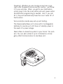
MANUAL AND USER GUIDE
Personal Alert System
With DECT Technology
www.ablenetinc.com
900-80238 rev A
08/11
PLEASE READ THIS MANUAL COMPLETELY AND
SAVE IT FOR REFERENCE.
Thank you for choosing Responsable by AbleNet – the
most unique Personal Emergency Response System in
the world, and covered by both US and Canadian patents.
Responsable is your personal link to Family, Friends, or
Emergency Personnel when needed. Responsable allows
you to program up to 4 numbers to be reached at the
push of a button.
With this unit - there are:
- No Activation Costs
- No Contracts
- No Monthly Fees
Up to 4 user programmable contacts to call anytime.
You can personalize the system to call:
- Up to 4 custom contacts
- Up to 4 custom contacts & then the 911 emergency operator
- 911 emergency operator.
Because you are speaking through the pendant, Responsable allows you to personally communicate your emergency from anywhere in your home or yard. Emergencies
can happen anywhere.
2
Traveling? Whether you are moving across town or going to visit the grand kids across the country - just throw
it in your suitcase. When you get to your destination,
simply plug it into the local phone jack and power outlet.
No additional programming is needed. And if you call
911, they will automatically have the local ‘caller ID’ of
that location.
Voice prompts provide easy set-up and testing.
The Responsable Base unit comes with 4 rechargeable
batteries to provide up to 24 hours of standby power in
the event of a power outage.
Need others to share the system in your home? No problem. You can add a total of up to 4 Pendants or Emergency Wall Communicators to one Base unit.
3
Table Of Contents
Limitation of Liability ................................................... 7
Installing the Batteries ................................................. 8
Pendant - small white batteries ...........................................8
Charging Extra Battery ........................................................9
Base - Larger AA Rechargeable Batteries ..............................9
Master ON/OFF switch ......................................................11
Connecting the Base Unit ........................................... 12
Power Connection ............................................................12
Telephone Connection ....................................................12
Use with existing phones ..................................................13
Key to LEDs on Base Unit and Pendant..............................13
How to Handle VoIP and DSL ...................................... 14
If Your Phone System is VoIP ............................................14
How to Handle DSL..........................................................15
Locating the Base Unit .....................................................15
Base Unit Options and Features .................................. 16
Friend’s List and Emergency Operator. ...............................16
Programming the Base Unit ........................................ 18
Programming Telephone Numbers .....................................18
Programming Notes..........................................................18
Programming Worksheet ...................................................21
Programming Special Features ..........................................22
Adding Additional Pendants to the System .........................25
Operating the System ................................................. 27
Emergency Dialing Using the Pendant ...............................27
Holding the Pendant ........................................................28
Hanging -Up....................................................................28
Answering an Incoming Call with the Pendant.....................29
Lanyard, Belt Clip or Wrist Strap. ......................................30
Battery Check ............................................................ 31
System Check ............................................................ 33
Operating Range ..............................................................35
Water Resistance .............................................................35
Periodic Testing / Maintenance .................................. 36
Replacing Batteries ..........................................................36
Out of Service Storage or Transportation .............................36
Troubleshooting Guide ............................................... 37
Information The FCC Wants You To Know ...........................39
4
Table Of Contents
General Warnings and Precautions ............................. 42
Important Safety Instructions ...................................... 43
Manufacturer Disclaimers and Limited Warranty .......... 44
Limited Warranty .............................................................45
Return Material Authorization (RMA) .................................47
Replacement Parts / Optional Accessories .................. 48
Product Specifications ............................................... 49
5
Package Contents
• Pendant
- 2 Rechargeable Li-Ion Batteries
• Responsable Base Unit
- 4 Rechargeable AA Batteries
•
•
•
•
•
•
Belt Clip
Wrist/Walker/Wheelchair strap
AC Adapter
Lanyard
Phone Cord
User Manual
Pendant
Base Unit
AC Adapter
W
em
st
Sy y
rt olog
Ale hn
al Tec
on T
rs EC
Pe ith D
M
M AN
M AN UAL
L’U ANUE UAL Y AND
TIL L E GU US
ISA T G ÍA ER
TEU UID DEL GUID
R
E D US E
UAR
E
IO
w.a
ww
Phone Cord
ble
tin
ne
om
c.c
90
8
002
A
v
re /11
38 08
User Manual
Rechargeable Li-Ion Batteries
Belt Clip
6
Wrist / Walker / Wheelchair Strap
Rechargeable AA Batteries
Laynard
Limitation of Liability
This page is a summary of the Disclaimer and Limited Warranty
disclosed in full at the end of this instruction manual. Read
them.
The purchaser agrees by using this product to the terms and conditions below and in the Disclaimer and Limited Warranty. The purchaser also agrees to read and follow all instructions and warnings
on the product and contained within these Installation and Operation
Instructions.
It will be the sole responsibility of the purchaser and any user to
assure that the Responsable by AbleNet product is installed and
programmed properly, and that the unit is used and maintained
correctly. This includes, but is not limited to, periodic use to
assure that the product, including batteries, are in proper working order, that the unit is located in an appropriate location in
the home, that the electrical outlet is supplying power, and that
the user has been educated as to the operation and functionality
of the product as a whole.
The equipment is not designed or guaranteed to prevent any
loss or injury. This Limited Warranty and Disclaimer of Liability
set forth in full at the end of this instruction manual constitutes
the terms of sale and use of the system (and accessories) equipment, and if, notwithstanding these terms of sale and use of the
product, there should arise any liability on the part of Manufacturer as a result of any cause whatsoever, regardless of whether
or not such loss, damage, or personal injury was caused by or
contributed to by Manufacturer’s negligence to any degree or
failure to perform any obligation or strict products liability, such
liability will be limited to an amount paid by the Purchaser for
the product or $300, whichever is greater.
Further, Manufacturer has no obligation to assure that calls are
made, received or responded to, nor is Manufacturer responsible
for acts, or consequences of the acts, of those responding.
Further, Manufacturer has no obligation to assure that calls are
made, received or responded to, nor is Manufacturer responsible
for acts, or consequences of the acts, of those responding.
7
Installing the Batteries
Pendant - small white batteries
The Pendant requires one of the white/Li-Ion (Lithium
Ion) batteries at any given time. The pendant should be
able to run up to 4 months on a fully charged battery.
The second battery is to be charging in the Base unit
when not being used in the Pendant. There is no risk of
over charging while in the base charger.
Battery Cap
To install the battery unscrew the battery cap of
the Pendant. Install the
battery with the negative side
up facing the cap. Screw
the cap back down snuggly
on the Pendant.
Li-ion 10440
The Pendant Batteries are shipped from the factory
with a partial charge – and will only standby a short
period of time. Your unit has 2 pendant batteries and
it is recommended to exchange the battery that is in
the base charger with the battery in the pendant after
the first day of use. This will ensure the battery in the
pendant is fully charged and will last several months
before needing to be exchanged/charged again.
You can check the battery status at any time by simply
pushing the gray battery test button on the back of the
Pendant for a second.
8
Charging Extra Battery
Place the extra Pendant battery into the front charging
area of the Base unit so that it will charge and be ready
when its time to swap the batteries around. The LED
on the right side will show red when charging and green
when fully charged.
LED
NOTE: These white batteries are special batteries that
are not available at your local store. See “Product Specifications” on page 49 for more details, or contact
www.PrimaryVolt.com to purchase replacement batteries.
Base - Larger AA Rechargeable Batteries
The Base unit requires 4 rechargeable NiMH batteries.
Unlike the Pendant battery - these are readily available
in many retail stores. Any value of 2400 or higher mAh
capacity is fine. These are to provide you with 24 hours
of battery back-up protection in the event of a power
failure. They will not be damaged by continually charging in the base unit.
9
When you first get your unit - these batteries will
probably be low, or even fully discharged - and will
need to be charged for 24 hours before being able to
provide you the 24 hour battery back-up protection.
Remove the cover on the bottom of the Base unit.
Install the 4 batteries in the battery compartment area.
A few seconds after you install these, you might hear
“Running on battery power”. When the unit is operating on the backup batteries, it will announce “Running
On Battery Power” twice and the RED Power LED will
flash continuously. If power is not restored within an 8
hour period, the unit will start to announce “Running
On Battery Power” once every 30 minutes until power is
restored or the back up batteries are depleted. (If you
do not hear this announcement, and the Power LED is
on solid, that means that you have already plugged in
the power adaptor).
10
NOTE: the voice prompts of “battery is OK” etc. only
apply to the pendant battery - not to the status of the
base unit’s batteries. It is recommended that you replace the base unit batteries every 2 years.
Master ON/OFF switch
The System has a Master ON/OFF switch on the bottom
of the base unit – just left of the rechargeable batteries.
This switch controls all power: back up batteries and
power from the AC adapter. This switch should be ON
at all times while the unit is in use. This switch should
only be turned OFF if the unit is taken out of service.
Master On/Off Switch
11
Connecting the Base Unit
Power Connection
Simply plug in the AC Adapter in to the nearest electrical outlet. Plug the other end of the AC power adapter
into the Base unit. You need to push the plug into the
opening in the Base unit and twist 90’ clockwise to lock
in place. To remove in the future, simply rotate 90’
counter-clockwise and pull outward.
rn
Lea t
de se
Co Re
V
7.5
DC
ne
ho
s
Jack
p
Tele
Fr
Lear
nM
e
od
DE
AB
1
F
C
4
3
MN
2
JK
I
GH
Ah
0m
50
nly
1O
91 Only
s
nd 1
Frie& 91
ds
ien
L
5
O
6
W
TU
Z
XY
9
V
RS
PQ
#
8
0
7
*
Caution: Do not plug the AC Adapter into an outlet which
is controlled by a switch. The switch could accidentally
be turned off, thus rendering the Base unit inoperable after
approximately 24 hours when the back up batteries become
discharged.
Telephone Connection
No special phone line or special service is required to
use your System. It works the same as any cordless
phone. (Touch Tone service is required). Simply plug one
end of the telephone cord into your telephone jack in the
12
wall, and the other end into either one of the telephone
jacks at the back of the Base unit. Note - you will feel
a ‘click’ when the cords are firmly seated in the receptacles.
Use with existing phones
It is recommended that you plug a conventional telephone into the open jack on the Base Unit. This will
allow the phone to be used by other members of your
household and is an important step when programming
emergency contact numbers.
Key to LEDs on Base Unit and Pendant
Both the Base Unit and Pendant use LEDs to indicate
device status.
BASE RED
Off:
Solid:
Flashing:
LED functions:
No AC power/No Back-up Battery Power
AC power
Running on Battery Back-up
BASE GREEN LED functions:
Off:
Standby
Solid:
Dialing/Talking or Learn Mode
Flashing: Pendant Learning or Low Pendant battery
PENDANT LED (single RED LED) Functions:
Off:
Standby
Solid:
Dialing or Talking
Flashing: Pendant Learning
13
How to Handle VoIP and DSL
If Your Phone System is VoIP
Voice-over-Internet Protocol (VoIP) is a telephone service
that sends your call over the Internet instead of through
the regular telephone system. The System will work with
most VoIP systems.
It is important (if you haven’t already done so) that you
register your physical address with your VoIP provider
and check to ensure that 911 service is available to you.
If you are unsure if your phone system uses VoIP, or to
find if your VoIP system is capable of calling 911, please
contact your telephone service provider.
To install the System, simply plug the Base unit into the
telephone jack (or adaptor jack) that you would normally
plug a regular telephone into. Note: if you have both a
working traditional phone line and a VoIP phone system
we recommend connecting the System to the traditional
phone line.
14
How to Handle DSL
If your home has DSL service for your computer, you
must use a DSL filter in line with the System or it will not
work. This filter can be obtained from a local electronics
supplier or your DSL service provider. See illustration
below.
DSL Filter
rn
Lea t
de se
Co Re
DC
ne
ho
p
Tele
Jack
V
7.5
Ah
0m
50
R
ILTE
F
DSL
nly
1O
91 Only
s
nd 1
Frie& 91
s
nd
s
Frie
n
Lear
Mo
de
Locating the Base Unit
For best results and longest range, locate the Base unit
in an area away from household appliances which could
present electrical interference. These include microwave
ovens, refrigerators, televisions, electric mixers or blenders, hair dryers, wifi routers or other cordless phones. Do
not place on a metal surface.
If more than one System is to be used in one home, it is
recommended that the Base units be located at least 10’
apart.
15
Base Unit Options and Features
The System can work right out of the box with no programming. To avoid programming any telephone numbers, simply slide the slide switch at the back of the
Base unit to the “911 Only” mode. Then, when you push
the blue button on the Pendant - you will be immediately connected to 911 emergency services. Note: If no
Friend’s list phone numbers are entered or a mistake was
made while programming the Responsable, it will automatically default to 911 for each of the 3 slide switch settings.
If you choose not to program any Friends numbers,
simply skip these next steps on “Programming Telephone Numbers” on page 18.
Code Learn
Reset
Telephone Jacks
Learn Mode
911 Only
Friends Only
Friends & 911
DC 7.5 V 500 mAh
Friend’s List and Emergency Operator.
In addition to being able to call 911, you can also program up to 4 telephone numbers of your choosing. For
example, you might have it programmed for 2 numbers to call your neighbor and if they are not available, to call
a family member. Even if you do program numbers into
the Base unit - you can still at any time choose to call
“911 Only” by sliding the switch at the back of the Base
unit. Programmed numbers remain in memory and will
be ready for use when you slide the slide switch back to
one of the “Friends” position. Disconnecting power or
changing batteries does not erase the numbers.
16
How does the Base unit know when to go to the next
number? The base unit will first dial the first number in
the “Friends” list. About 10 seconds into the conversation, the Base unit will interrupt the call and announce
“This is an emergency call. If you want to continue this
call - Press 5 now. Otherwise, we will hang up and call
the next contact or emergency operator”. At this point
- the person that is being called must press the “5” key
on their telephone if they want to continue the call. If
they don’t press “5”, then the Base unit will assume
they are unavailable to talk, or that it may be an answering machine or a child - at which point it hangs up and
goes on to the next number. It is important to instruct
the people you have programmed into your “Friends” list
to press “5” when they get this call, and when they hear
this message.
ABC
DEF
GHI
JKL
MNO
PQRS
TUV
WXYZ
1
4
7
2
5
8
3
6
9
NOTE: the “Press 5” message is NOT played anytime
the System unit is calling 911.
17
Programming the Base Unit
Programming Telephone Numbers
If you choose to only contact 911 - and not a custom
telephone number - skip these next steps (and go to
page 16) - and make sure your slide switch on the back
of the Base unit is set to “911 only”.
Programming Notes
• As you program the system using your telephone, you
will hear the base unit speak each number as it is
pushed.
• Dial slowly and listen for each number to be announced. If you did not hear the announcement - the
number was not recorded.
• The System can learn telephone numbers up to 32 digits long. You do not have to program all 4 numbers
• To add a pause in your number sequence......insert a
“*” for a 1 second pause. Insert “**” a 2 second
pause.
• Remember to program a 1 before any long distance
numbers.
• Remember to program any AREA CODE numbers if
needed.
• Remember to program any PREFIX NUMBERS (like 9 to
get an outside line) if needed.
• If at any time a new number is programmed into the system, all old numbers will be erased.
18
Step 1: Write out the numbers - use the worksheet on
page 21. Below we will refer to Number 1 as the first
number, Number 2 as the second number etc. Include
area-codes and a 1 or 9 if they are needed for dialing.
Step 2: Using the conventional telephone plugged into the
Base Unit, (page 12) establish a live phone connection with a friend or family member. A personal mobile
phone in the same house is recommended. Tell the
recipient that you are programming your device and ask
that they simply not hang up until you are finished. This
important step keeps the Responsable System from actually calling your emergency contacts as you enter them.
Step 3: Move the slider switch on the back of the
Base Unit to “Learn Mode”. You will hear an audible
announcement of this position.
Step 4: Using the conventional telephone, enter the programming password: 1 2 3 4 #. The Base Unit is now in
Programming Mode.
Step 5: With your worksheet as a reference, use the telephone handset to slowly dial the number of your first
emergency contact. The Base Unit will announce each
number as it is entered.
Note: If you do not hear a number announced, the number was not recorded. Re-enter that individual number
before moving on.
When you are finished entering the first number, press # to
save and move to the second Emergency Contact number.
Step 6: Repeat Step 5 for additional numbers. After entering
and saving any Emergency Contact number, you may press
# a second time to exit Programming Mode and cease
entering additional numbers.
19
Note: Once you exit Programming Mode, adding additional numbers requires starting over and re-entering ALL
Emergency Contact numbers. You cannot simply add a
new number to the end of the sequence or change Emergency Contact number 2, for example.
Step 7: When you have completed entering all Emergency Contact numbers, the Base Unit will speak, “End
of programming”. Move the slider switch back to Friends
& 911, Friends Only, or 911 Only to exit Programming
Mode.
Code Learn
Reset
Telephone Jacks
Learn Mode
20
911 Only
Friends Only
Friends & 911
DC 7.5 V 500 mAh
Programming Worksheet
1.
Call a friend or family member on your telephone.
2.
Slide switch to LEARN MODE [voice prompt – Learn Mode]
3.
Enter: “1 2 3 4 #” [voice prompt – one, two, three, four, “#” Enter 1st phone number followed by # ]
4.
(Enter the 1st phone number then “#”) :
__ __ __ __ __ __ __ __ __ __ __ __ __ __ __ __ #
[voice prompt – numbers as you enter them then “Enter 2nd phone
number followed by #]
Press # again to skip remaining numbers, or
5.
(Enter the 2nd phone number then “#”)
__ __ __ __ __ __ __ __ __ __ __ __ __ __ __ __ #
[voice prompt – numbers as you enter them then “Enter 3rd phone
number followed by #]
Press # again to skip remaining numbers, or
6.
(Enter the 3rd phone number then “#”) :
__ __ __ __ __ __ __ __ __ __ __ __ __ __ __ __ #
[voice prompt – numbers as you enter them then “Enter 4th phone
number followed by #]
Press # again to skip remaining 4th number, or
7.
(Enter the 4th phone number then “#”) :
__ __ __ __ __ __ __ __ __ __ __ __ __ __ __ __ #
[voice prompt – numbers as you enter them]
8.
[voice prompt – “End of programming”]
9.
Slide switch back to Friends & 911, Friends Only or 911 Only
10. Programming complete!
21
Programming Special Features
There are a few features you can program into the
System. A typical user will not need these features - and
may skip to the next page. If you choose to change any
of these features, use the same programming set-up as
before:
1. First establish a phone connection with another
phone such as your cell phone.
2. Slide the switch at the back of the Base to “Learn
Mode” then use these directions for any option you
choose to change:
Option #1 – Dial 9 Before Number (important if your phone
system requires a 9 before getting an outside line - particularly when it calls 911)
1. Enter 1234** [Voice prompt – Option Mode]
2. Enter – 1 [Voice prompt – Dial 9 before number, 1
for YES – 3 for NO
3. Enter either 1 or 3
[Voice prompt 1 – YES]
or, [Voice prompt 3 – NO] – FACTORY SETTING
4. Enter # (to exit programming mode) Voice prompt –
Programming complete]
5. Slide Programming Switch to “Friend, 911 – Friends
Only – 911 Only”
Option #4 – DEMO/Tradeshow Mode – THIS MODE IS FOR
DEMO MODE ONLY FOR SALESPERSONS. This feature
22
is used to DEMO the unit without having access to a
telephone line. We use this feature with a Viking DLE200 test box. NEVER LEAVE THE UNIT IN THIS MODE
FOR NORMAL OPERATION.
1. Enter 1234**
[Voice prompt – Option Mode]
2. Enter – 4 [Voice prompt – DEMO Tradeshow Mode],
1 for YES
3 for NO– FACTORY SETTING
3. Enter either 1 or 3
[Voice prompt 1 – YES]
[Voice prompt 3 – NO]
4. Enter “#” (to exit programming mode)
[Voice prompt – Programming complete]
5. Slide Programming Switch to “Normal Operation”
[Voice prompt – “Emergency Call Mode”]
Option #5– Delete - “This is an Emergency, Press 5” message (This option is only for special cases. We do not
recommend that you change this option without careful
thought.)
1. Enter 1234** [Voice prompt – Option Mode]
2. Enter – 5 [Voice prompt – Play message, This is an
emergency, press 5 message, 1 for YES – 3 for NO]
3. Enter either 1 or 3
[Voice prompt 1 – YES] – FACTORY SETTING
or, [Voice prompt 3 – NO]
23
4. Enter # (to exit programming mode) [Voice prompt –
Programming complete]
5. Slide Programming Switch to “Friend, 911 – Friends
Only – 911 Only”
Option #9 – Reset To Factory Settings (This option will
ERASE all programmed friend numbers and reset all
options.)
1. Enter 1234** [Voice prompt – Option Mode]
2. Enter – 9 [Voice prompt – Reset to factory settings, 1
for YES – 3 for NO
3. Enter either 1 or 3
[Voice prompt 1 – YES] or [Voice prompt 2 – NO]
4. Enter # (to exit programming mode)
[Voice prompt – Programming complete]
5. Slide Programming Switch to “Friend, 911 – Friends
Only – 911 Only”
Note: phone numbers are erased so regardless of the
switch setting, the unit will call 911 if the emergency
button is pushed.
Changing 3-Digit Emergency Contact Number. (This is
primarily used when a person is living in another country
other than North America where the emergency number
is different than 911).
1. Enter 1234*#*# [Voice prompt – Enter New 3 Digit
Emergency number]
2. Enter XXX (new emergency number)
[Voice prompt – Programming complete]
24
Adding Additional Pendants to the System
The System comes with one Pendant. If you want to add
additional pendants to your system - follow the directions here.
The Pendant’s unique ID code should already be paired
with the Base unit when it came from the factory. You
can add a total of 4 Pendants and Emergency Wall Communicators (see “Replacement Parts / Optional Accessories” on page 48) to the system by pairing each
pendant’s ID code with the Base unit.
To pair a new Pendant with the Base unit:
On the Base Unit:
1. Push and release the RED Code Learn button on the
back of the base unit. You will hear a voice prompt
“Pendant Learning”
On the Pendant:
2. PUSH the Gray Battery Test button and then IMMEDIATELY push the Blue button –HOLD both buttons
until you hear “Pendant Learning” from the pendant
- then release both buttons on the pendant.
• If “Base and Pendant out of Range” or “Pendant
Learning Failed” is heard from the pendant, stop wait 30 seconds and start at step #1 again.
(Note: For the Emergency Wall Communicator, push and
hold the Red “Help” and gray test button).
25
3. When Pendant learning has been successful you will
hear “All Systems are OK” and then it will announce
the call setting that the base is set to – Friends 911
Mode, Friends Only or 911 Only.
• If “Base and Pendant out of Range” or “Pendant
Learning Failed” is heard from the Base or Pendant,
STOP - wait 30 seconds and start at step #1 again.
Notes:
• You have up to 45 seconds after pushing the RED Code
Learn button on the base unit to get the pendant to
enter “Pendant Learning” Mode.
• Teaching additional pendants does not erase previously
learned pendants.
• The base unit will automatically exit the pendant learning mode after several seconds or if Pendant Learning
Failed.
• When more than 1 pendant is paired with the base, the
base unit will announce the pendant number when doing testing like the battery test.
At a later point in time, you might want to erase your
previously learned Pendants. You can erase all previously learned Pendants by simply holding down the
red Code Learn button at the back of the Base unit for
8 seconds. You will hear the confirmation of “Previous
Pendant Codes Erased” from the Base unit. After that,
you can program a new Pendant to the base unit following the steps above as desired.
26
Operating the System
Emergency Dialing Using the Pendant
In the event of an emergency, press the Blue button on
the front of the Pendant. When this button is pressed for
2 seconds, the System will automatically start dialing
from the list of numbers.
Blue Button
If set to the “911 only” mode, then the 911 emergency
operator will be called. When the emergency response
operator answers, speak in a normal voice and you will
be heard.
If set to the “Friends only” mode - the system will dial
the first telephone number in the list. If no one is available for that number, it will dial the second number, etc
- until it gets to the end of the list. It will then repeat
from the top of the list.
If set to the “Friends and 911” mode - the system will
dial the first telephone number in the list. If no one is
available for that number, it will dial the second number,
etc - until it gets to the end of the list. After that, it will
then dial the 911 emergency operator.
27
Holding the Pendant
Hold the Pendant as you would any normal telephone
receiver - close to the head so that you can hear the
other person being called - and they can hear you speaking.
Hanging -Up
If you choose to cancel the call once initiated - you can
simply push the Gray button on the back for a second
to cancel the call and you will hear “Hanging up”. The
recipient can force a hang up by pushing “9”, or simply
hang up their end. The System will hang-up automatically over the next 1 to 3 minutes. Push the gray button
on the Pendant to end the call immediately. The unit
will automatically reset and be ready for the next call.
Li-ion 10440
28
Grey Button
Answering an Incoming Call with the Pendant
The System has the ability to answer incoming calls
through the pendant or the Emergency Wall Communicator accessory. When the phone rings (the pendant
will NOT ring), push the Blue Emergency button or Red
“HELP” button on the Emergency Wall Communicator
for 2 seconds to answer the call.
Red “Help” Button
Blue Button
t
Tes
Pendant
Optional Emergency Wall Communicator accessory
Example:
1. Incoming call to customers home
2. Base unit rings
3. Push the Blue Emergency button on pendant for 2
seconds to activate the pendant
4. The System will answer the incoming call – talk using pendant
5. To end the call:
a. User pushes the Gray test button on pendant to
hang-up.
b. Or, the calling person pushes #9 to end call and
reset unit
c. Or, the unit listens for 3 minutes of silence and
then hangs-up and resets
29
Lanyard, Belt Clip or Wrist Strap.
The System includes 3 accessories for carrying/wearing
the Pendant: a lanyard, belt clip, and wrist-strap. The
wrist-strap can also be used to attach the Pendant to a
wheelchair, bed rail or other object as-needed.
30
Battery Check
To check the status of the Pendants battery, Press and
Release the Gray button at the back of the Pendant. A
voice announcement will announce one of the following
messages:
Battery is ok-Check the battery condition twice a month.
Battery is low-The battery should be replaced within the
next week.
Replace battery now-The battery should be replaced
immediately.
To replace the battery - simply exchange the battery in
the Pendant with the battery that has been charging in
the Base unit.
Note: If there is no response after pressing the button
for one second or more, the battery is dead and must be
replaced immediately.
Li-ion 10440
Grey Button
31
The battery should be tested at least twice a month along
with the System Check outlined on the next page.
When it gets to the point after a few years that the
pendant battery only lasts 4 weeks before needing to be
charged - it is then time to replace both the Pendant
batteries.
Note: This is a very unusual battery not available at most
outlets. Order replacement batteries from www.PrimaryVolt.com as directed on”Replacement Parts / Optional
Accessories” on page 48.
Note: The pendants are monitored by the base unit.
The pendant reports to the base every 13 hours. If the
battery condition is “Replace Battery Now”, the base
unit will call the first ‘Friend’ number and play the voice
prompt [Pendant number X, Replace Battery Now]. The
voice prompt is played 10 times, then hangs up and
resets.
And, if the base unit misses 4 reports from the pendant in a row (52 hours), the base unit will call the first
‘Friend’ number and play the voice prompt [Pendant
Number X, Not in communication]. The voice prompt is
played 10 times, then hangs up and resets.
Pressing the 9 on the phone keypad on either of these
messages will stop the announcement and cause the
unit to reset.
If the first ‘Friend’ gets either of these announcements,
please make arrangements as soon as possible to service
or replace the pendant.
The unit will not call 911 to report a Replace Battery
Now or Pendant Failed condition. A ‘Friend’ number
must be programmed for this feature to work.
32
System Check
The Gray button on the back of the pendant will also
perform a SYSTEM CHECK. Press and hold this button
for more than four (4) seconds. One of the following
announcements will be made.
“All systems are ok.”
This confirms the following:
- Battery status.
- The Pendant is working.
- The Base unit is working.
- The Base unit is connected to a working phone line.
- The Pendant is within range of the Base unit.
“System cannot detect dial tone.”
- The Base unit is not connected to the phone line or can
not get a dial tone for some reason.
“Base and Pendant out of range.”
This confirms one or more of the following:
- The Pendant and Base unit are not communicating with
each other or are out or range.
- The Pendant has malfunctioned.
- The Base has malfunctioned.
Li-ion 10440
Grey Button
33
If you receive a failure notification, please refer to the
“Troubleshooting Guide” on page 37 of this manual to
determine the cause.
This testing feature is very useful - allowing you to confirm that the system has coverage from all parts of your
home. Simply walk to the various parts of your home and
push the Battery Check / System Check button until you
hear the 4 beeps and then the dial tone. You can then
release the button, and you will hear the voice prompt
“All Systems are OK”, “Pendant and Base out of Range”,
or “System Cannot Detect Dial Tone”.
NOTE: If your telephone service offers voice mail and
the voice mail system uses a Stutter Dial Tone to notify
you of a message, the system test may fail – “cannot
detect dial tone” if a system test is made with a message
waiting. This is normal as the System is “listening” for
a conventional dial tone. Check your messages so the
dial tone returns to a solid tone and test again. In the
event of an emergency, the System will dial the emergency number regardless of a standard or stutter dial tone.
Caution - To ensure proper operation, this equipment
must be installed according to the these instructions.
We highly recommend that you perform this System
Check after set-up and installation and at least twice a
month to confirm that your system is working properly
and that the pendant and base unit are in good communication and that the base unit can get a dial tone. It is
also recommended to perform this system check after a
lightning storm that could damage the base unit which is
plugged into the phone line.
34
Operating Range
The operating range of your System will depend on many
factors including intervening walls, electrical interference or various appliances such as vacuum cleaners,
microwave ovens, mixers, coffee grinders, hair dryers and
other sources of electrical noise around the house. The
system should cover your typical home and a short distance into your yard. Perform the System Check on page
20 to determine the boundaries of your system to know
the limits of operation in your home and surroundings.
Water Resistance
The System will resist splashes from water - i.e as in
the shower. However, it should never be submerged or
exposed to water continuously.
35
Periodic Testing / Maintenance
It is highly recommended that you preform a full System
Check (see page 33) at least twice a month. This will
confirm that the Pendant battery is in good condition
and that the Base unit is able to get a dial tone.
Replacing Batteries
Replace the Base unit batteries every 2 years - or as
needed. Be sure to purchase NiMH AA batteries with
2400 mAh or greater capacity. A set of batteries in
good condition and fully charged will supply 24 hours
of back-up in the event of a power outage. You can test
this by unplugging the AC Adapter and hearing the voice
prompts. When the unit is operating on the backup
batteries, it will announce “Running On Battery Power”
twice and the RED Power LED will continue to flash. If
power is not restored within an 8 hour period, the unit
will start to announce “Running On Battery Power” once
every 30 minutes until power is restored or the back up
batteries are depleted. (Note that lower capacity batteries can be used - but they will give less back-up time).
Out of Service Storage or Transportation
When storing, traveling or shipping the Base unit turn
the Master ON/OFF switch to OFF so that the “Running
on battery power” announcement is disabled. Remember to turn the Master ON / OFF switch to ON when it is
put back in service.
Caution - This equipment cannot call out when other equipment (telephone or a computer modem, etc.) are in use on
the same phone line. In the event someone is on the telephone elsewhere in the home when you activate the System
for an emergency situation you will be connected to the
person currently on the telephone line in your home.
36
Troubleshooting Guide
What if I can’t get the System to work?
Step 1 – Check the PENDANT.
What to do:
Press the Gray Battery Test / System Check button on
the back of the Pendant.
What to expect:
A voice should announce the condition of the battery.
A light on the front of the Pendant will come on.
If nothing happens, the most likely cause is that the battery is dead or has been installed backwards.
If the Pendant says “Battery ok”, go on to step 3.
Step 2 – Check the connections on the BASE UNIT
What to do:
Make sure the AC Adapter is plugged into a live AC
outlet and into the Base unit.
Make sure the Master ON / OFF switch is ON
What to expect:
The Red POWER light will be on if the Base unit is
connected to power.
If the POWER light is on and the Base unit is connected to a working phone line, go on to step 3.
37
Step 3 – Make sure the Pendant and the Base unit are communicating with each other.
Background information: The Pendant and the Base unit
are connected by a wireless radio link. They must be
synchronized to work together. They should have already
been synchronized at the factory, but resetting this is
simple.
What to do:
Follow the steps on page 16: Adding Additional Pendants to the System
Now perform the System Check test again (page
33) to make sure all is well
Step 4 – Push the gray RESET button with a pen at the
back of the base unit (next to the power cord). Check
the system. If it is now working skip the remaining
steps..
If your Responsable by AbleNet is still not working, call our
TECH SUPPORT department at 800-322-0956.
38
Information The FCC Wants You To Know
FCC ID: TYD3X911
This device complies with Part 15 of the FCC Rules.
Operation is subject to the following two conditions: (1)
this device may not cause harmful interference, and
(2) this device must accept any interference received,
including interference that may cause undesired operation.
Privacy of communications may not be ensured when
using this product.
NOTE: This equipment has been tested and found to
comply with the limits for a Class B device, pursuant to
Part 15 of the FCC Rules. These limits are designed to
provide reasonable protection against harmful interference in a residential installation. This equipment generates, uses and can radiate radio frequency energy and, if
not used in accordance with the instructions, may cause
harmful interference to radio communications. However,
there is no guarantee that interference will not occur in
a particular installation. If this equipment does cause
harmful interference to radio or television reception,
which can be determined by turning the equipment off
and on, the user is encouraged to try to correct the interference by one or more of the following measures:
- Reorient or relocate the receiving antenna.
- Increase the separation between the equipment and receiver.
- Connect the equipment into an outlet on a circuit different
from that to which the receiver is connected.
- Consult the dealer or an experienced radio/TV technician
for help.
Canada IC: 8471A-3X911 This Class B digital apparatus complies with Canadian ICES-003.
39
This equipment also complies with Part 68 of the FCC
rules and the requirements adopted by the ACTA:
US:TYDW400B3X911
REN: 0.0B
a) On the bottom of this equipment is a label that
contains, among other information, a product identifier
- in this case, US:TYDW400B3X911. If requested, this
number must be provided to the telephone company.
b) An applicable certification jacks Universal Service
Order Codes (USOC) for the equipment is provided (i.e.
RJ11C) in the packaging with each piece of approved
terminal equipment.
c) A plug and jack used to connect this equipment to
the premises wiring and telephone network must comply
with the applicable FCC Part 68 rules and requirements
adopted by the ACTA. A compliant telephone cord
and modular plug is provided with this product. It is
designed to be connected to a compatible modular jack
that is also compliant. See installation instructions for
details.
d) The Ringer Equivalent Number (REN) is used to
determine the number of devices that may be connected
to a telephone line. Excessive RENs on a telephone line
may result in the devices not ringing in response to an
incoming call. In most but not all areas, the sum of the
RENs should not exceed five (5.0). To be certain of the
number of devices that may be connected to a line, as
determined by the total RENs, contact the local telephone company. Since our product has no ringer - the
REN equals 0.0.
e) If this equipment (model 35911) causes harm to a
telephone network, the telephone company will notify
you in advance that temporary discontinuance of service
may be required. But if advance notice isn’t practical,
the telephone company will notify the customer as soon
as possible. Also, you will be advised of your right to file
a complaint with the FCC if you believe it is necessary.
40
f) The telephone company may make changes in its
facilities, equipment, operations or procedures that
could affect the operation of the equipment. If this
happens the telephone company will provide advance
notice in order for you to make necessary modifications
to maintain uninterrupted service.
g) Should you experience trouble with this equipment,
please contact AbleNet at 800-322-0956 for repair or
warranty information. If the equipment is causing harm
to the telephone network, the telephone company may
request that you disconnect the equipment until the
problem is resolved.
h) Please follow instructions for repairing if any (e.g.
battery replacement section); otherwise do not alternate
or repair any parts of device except specified.
i) Connection to party line service is subject to state tariffs. Contact the state public utility commission, public
service commission or corporation commission for information.
j) NOTICE: If your home has specially wired alarm
equipment connected to the telephone line, ensure the
installation of this model does not disable your alarm
equipment. If you have questions about what will disable alarm equipment, consult your telephone company
or a qualified installer.
41
General Warnings and Precautions
Warning!
• Manufacturer DOES NOT represent this unit to be
waterproof. To reduce the risk of damage to the unit,
DO NOT expose the pendant or base unit to prolonged
water, rain or moisture.
• The System is intended for residential use only. It may
not work properly if connected to some commercial
phone systems.
• The System works with tone dialing systems only. Do
not use if you have pulse dialing only.
• This product and/or accessories may contain lead, a
chemical known to the State of California to cause
birth defects or other reproductive harm.
Note: The System does not interfere with pacemakers.
42
Important Safety Instructions
When using your System , please observe the following
instructions in order to reduce the risk of personal injury,
electrical shock, or fire.
1. Save these instructions for future reference.
2. Read all instructions carefully and make sure you
understand them.
3. Unplug this product from the electrical outlet before
attempting to clean it. Do not use any liquids for
cleaning either the Base unit or the Pendent. Use
only a soft damp cloth.
4. Do not locate the Base unit near any source of water,
such as in the bathroom, near a sink in the kitchen,
or the like.
5. Do not open the unit, (except the battery compartments as directed in these instructions) on the Pendant for any reason. Any attempt to open the case of
the Base unit or the Pendant will void the warranty
and may damage the unit or prevent it from working
properly.
6. Do not use any power source other than that supplied from Manufacturer specifically for this product.
Use of any other power source could damage your
unit or make it unsafe.
7. Always dispose of batteries properly. Never thrown
batteries into a fire. Consult your local ordinances
for proper battery safety.
43
Manufacturer Disclaimers and Limited Warranty
COMMUNICATION AND RESPONSE LIMITATIONS: Purchaser acknowledges that signals which are transmitted
over telephone lines, or other modes of communication
pass through communication networks wholly beyond
the control of Manufacturer and are not maintained by
Manufacturer, and, therefore, Manufacturer shall not be
responsible for any equipment or communication failure
which prevents transmission signals from reaching your
contact list including emergency 911 operators or damages arising therefrom. Purchaser acknowledges that
Manufacturer provides no response to its equipment. The
equipment is designed to communicate with the contact
list of your choice as well as emergency 911 operators
and Manufacturer is not and shall not be responsible
for ambulance, police or other emergency response time
or that any response will be provided by the anyone on
your contact list including the emergency 911 response
center.
ELECTRIC AND TELEPHONE SERVICE IS NECESSARY AND
PURCHASER’S RESPONSIBILITY: Purchaser acknowledges
that the equipment (including optional Battery Backup accessory) plugs into a standard land line telephone
jack and communicates over standard telephone lines
using two way voice communication. You must use a
special adaptor (not supplied) for the equipment to work
with VOIP Internet transmission. VOIP Internet will not
work when your electricity service is interrupted unless
you have battery back up for your computer. Purchaser
acknowledges that the equipment requires 110 Volt AC
power and electrical outlets and receptacles, telephone
hook-ups, RJ11 Block or equivalent, all of which is Purchaser’s responsibility to obtain and maintain.
44
TESTING AND SERVICE OF Responsable EQUIPMENT: The
equipment, once installed, are in the exclusive possession and control of the Purchaser, and it is Purchaser’s
sole responsibility to test the operation of equipment and
request warranty service if the equipment is under warranty.
Limited Warranty
AbleNet Manufactured Products include a ‘Two Year
Limited Warranty’. This warranty is against defects in
materials and manufacturing for two full years from the
date of purchase. If documentation identifying the date
of purchase is not supplied, the warranty period will be
determined as two years from the date of manufacture
stamped inside the product. The limited warranty is not
transferable and is only offered to the first customer who
purchases the product.
If a valid claim is received during the warranty period,
at AbleNet’s option and to the extent permitted by law,
AbleNet will either (i) repair the defect at no charge, using
new or refurbished replacement parts at no charge to you,
(2) exchange the product with a product that is new or
which has been manufactured from new or serviceable
used parts and is at least functionally equivalent to the
original product, or (3) refund the purchase price of the
product. AbleNet may request that you replace defective
parts with new or refurbished user-installable parts that
AbleNet provides in fulfillment of its warranty obligation. A replacement product or part assumes the remaining warranty of the original product or ninety (90) days
from the date of replacement or repair, whichever provides longer coverage for you. When a product or part is
exchanged, any replacement item becomes your property
and the replaced item becomes AbleNet’s property. Parts
provided by AbleNet in fulfillment of its warranty obligation must be used in products for which warranty service
is claimed. When a refund is given, the product for which
the refund is provided must be returned to AbleNet.
45
THE FOLLOWING ARE EXCLUDED FROM THE ABOVE
LIMITED WARRANTY COVERAGE:
• Wear and Tear. Periodic maintenance, repair, and
replacement of parts due to normal wear and tear are
excluded from coverage.
• Abuse. Defects or damage that result from: (a)
improper operation, storage, misuse or abuse, accident
or neglect, such as physical damage (cracks, scratches,
etc.) to the surface of the product resulting from misuse;
(b) contact with liquid, water, rain, extreme humidity or
heavy perspiration, sand, dirt or the like, extreme heat,
or food; (c) subjecting the products to abnormal usage
or conditions; or (d) other acts which are not the fault of
AbleNet or manufacturer, are excluded from coverage
IMPLIED WARRANTIES OF MERCHANTABILITY AND
FITNESS FOR A PARTICULAR PURPOSE, SHALL BE
LIMITED TO THE DURATION OF THE LIMITED WARRANTY, OTHERWISE THE REPAIR, REPLACEMENT, OR
REFUND AS PROVIDED UNDER THIS LIMITED WARRANTY IS THE EXCLUSIVE REMEDY OF THE CONSUMER, AND IS PROVIDED IN LIEU OF ALL OTHER
WARRANTIES, EXPRESS OF IMPLIED. IN NO EVENT
SHALL ABLENET BE LIABLE, WHETHER IN CONTRACT
OR TORT (INCLUDING NEGLIGENCE) FOR DAMAGES
IN EXCESS OF THE PURCHASE PRICE OF THE PRODUCT OR FOR ANY INDIRECT, INCIDENTAL, SPECIAL,
OR CONSEQUENTIAL DAMAGES OF ANY KIND, OR
LOSS OF REVENUE OR PROFITS, LOSS OF BUSINESS,
LOSS OF INFORMATION OR DATA, SOFTWARE OR
APPLICATIONS, OR OTHER FINANCIAL LOSS ARISING OUT OF OR IN CONNECTION WITH THE ABILITY
OR INABILITY TO USE THE PRODUCTS TO THE FULL
EXTENT. THESE DAMAGES MAY BE DISCLAIMED BY
LAW. SOME STATES AND JURISDICTIONS DO NOT
ALLOW THE LIMITATION OR EXCLUSION OF INCIDENTAL OR CONSEQUENTIAL DAMAGES, OR LIMITATION
46
ON THE LENGTH OF AN IMPLIED WARRANTY, SO
THE ABOVE LIMITATIONS OR EXCLUSIONS MAY NOT
APPLY TO YOU. THIS WARRANTY GIVES YOU SPECIFIC
LEGAL RIGHTS, AND YOU MAY ALSO HAVE OTHER
RIGHTS THAT VARY FROM STATE TO STATE OR FROM
ONE JURISDICTION TO ANOTHER.
Return Material Authorization (RMA)
No Product may be returned directly to AbleNet without first contacting AbleNet at 1(800)322-0956 or via
the website at www.ablenetinc.com, for a Return Material Authorization (“RMA”) number. If it is determined
that the Product may be defective, you will be given an
RMA number and instructions for Product return, repair,
replacement, or other solution. An unauthorized return,
i.e. one for which an RMA number has not been issued,
will be returned to you at your expense. Authorized
returns are to be shipped prepaid and insured to the
address on the RMA in an approved shipping container.
Your original box and packaging materials should be kept
for storing or shipping your Product. To request an RMA,
please call us at 1(800)322-0956 or visit our website.
47
Replacement Parts / Optional Accessories
Rechargeable Li-Ion Batteries
www.primaryvolt.com
Rechargeable AA Batteries
www.primaryvolt.com
t
Tes
Pendant
PN: 80001900
Emergency Wall Communicator
PN: 80001800
This wall button can be permanently
mounted to the bedroom or bathroom
wall - and provide the same 2-way
voice communication, just like the
Pendant in an emergency.
Visit AbleNet’s website at www.ablenetinc.com or call
1-800-322-0956 for more product information and pricing.
48
Product Specifications
RF Technology:
1.9 Ghz DECT System
Operating Range
Covers your typical American
house and into the front, back,
and side yards.
Power Adapter Ratings
Input: 110 VAC
Output: 7.5 volts DC - 500 mA
Base Unit Power Consumption
120 mA in standby mode
200 mA when dialing
Back-up Battery Supply
AA NiMH 2400 mAh batteries
(4 pieces). Should be replaced
every 2 years. (Note that lower
or larger capacity batteries can
be used - they will just give less
or more back-up supply time).
Back-up Operation Duration
24 hours with freshly charged
batteries
Dialing Style
Touch-Tone only
Telephone Number Length
32 digits maximum
Telephone Numbers
Can learn up to 4 numbers plus
the 911
Pendant Battery Life on Full Charge
More than 1 hour of talk time.
Pendant Batteries
3.6 or 3.7 volt 350 mAh Li-Ion
(2 pieces)
Battery size 10440.
Should be replaced every 2
years
Purchase replacement batteries
at www.PrimaryVolt.com
Pendant water-resistance
Water Spray Standard IPX5
(shower only)
Number of Pendants/Base Unit
Up to a total of 4 Pendants or
Emergency Wall Communicators
can be programmed to one Base
unit.
Operating Temperature
32˚ to 120˚ F. (0˚ to 49˚ C).
49
50
51
AbleNet, Inc.
Mpls./Saint Paul, MN 55113
800-322-0956
www.ablenetinc.com
www.ablenetinc.com