1
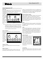
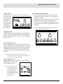
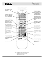
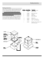
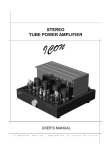
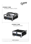
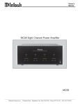
OWNERS MANUAL C15 Preamplifier C15 McIntosh Laboratory, Inc. 2 Chambers Street Binghamton, New York 13903-2699 Phone: 607-723-3512 FAX: 607-724-0549 Thank You, Please Take A Moment, Customer Service and Table of Contents Thank You Your decision to own this McIntosh C15 Preamplifier ranks you at the very top among discriminating music listeners. You now have The Best. The McIntosh dedication to Quality, is assurance that you will receive many years of musical enjoyment from this unit. Please take a short time to read the information in this manual. We want you to be as familiar as possible with all the features and functions of your new McIntosh. Please Take A Moment The serial number, purchase date and McIntosh dealer name are important to you for possible insurance claim or future service. The spaces below have been provided for you to record that information: Serial Number: Purchase Date: Table of Contents Thank You .......................................................................... 2 Please Take a Moment ....................................................... 2 Customer Service ............................................................... 2 Table of Contents ............................................................... 2 Safety Instructions ............................................................. 3 Introduction ........................................................................ 4 Performance Features ........................................................ 4 Installation ......................................................................... 5 Rear Panel Connections ..................................................... 6 How to Connect ................................................................. 7 How to Connect for Video Switching ................................ 8 Front Panel Controls, Push-Button and Switches .............. 9 How to Operate ................................................................ 10 HR033 Push-Buttons ....................................................... 12 How to Operate by Remote Control ................................ 13 Specifications .................................................................. 14 Packing Instruction .......................................................... 15 Dealer Name: Technical Assistance If at any time you have questions about your McIntosh product, contact your McIntosh dealer who is familiar with your McIntosh equipment and any other brands that may be part of your system. If you or your dealer wish additional help concerning a suspected problem, you can receive technical assistance for all McIntosh products at: McIntosh Sales Corporation 661 W. Redondo Beach Blvd. Gardena, CA 90247 Phone: 888-979-3737 Fax: 310-217-9288 Customer Service If it is determined that your McIntosh product is in need of repair, you can return it to your dealer. You can also return it to the McIntosh Laboratory Service Repair department. For assistance on factory repair return procedure, contact the McIntosh Repair Department at: McIntosh Laboratory, Inc. 2 Chambers Street Binghamton, New York 13903 Phone: 607-723-3515 Fax: 607-723-1917 Copyright 1998 ã by McIntosh Laboratory, Inc. 2 NOTES: 1. Connecting Cables are available from the McIntosh Parts Department: Data and Power Control Cable Part No. 170-202 Six foot, shielded 2 conductor, with 1/8 inch stereo mini phone plugs on each end. 2. For additional connection information, refer to the owners manual(s) for any component(s) connected to the C15 Preamplifier. 3. There is a built-in turn on delay which will mute the speaker outputs for approximately two seconds when the preamplifier is turned on. Safety Instructions IMPORTANT SAFETY INSTRUCTIONS! PLEASE READ THEM BEFORE OPERATING THIS EQUIPMENT. WARNING SHOCK HAZARD DO NOT OPEN. The lightning flash with arrowhead, within an equilateral triangle, is intended to alert the user to the presence of uninsulated dangerous voltage within the products enclosure that may be of sufficient magnitude to constitute a risk of electric shock to persons. AVIS RISQUE DE CHOC NE PAS OUVRIR. The exclamation point within an equilateral triangle is intended to alert the user to the presence of important operating and maintenance (servicing) instructions in the literature accompanying the appliance. NO USER-SERVICEABLE PARTS INSIDE. REFER SERVICING TO QUALIFIED PERSONNEL To prevent the risk of electric shock, do not remove cover (or back). No user serviceable parts inside. Refer servicing to qualified personnel. General: 1. Read all the safety and operating instructions, contained in this owners manual, before operating this equipment. 2. Retain this owners manual for future reference about safety and operating instructions. 3. Adhere to all warnings and operating instructions. 4. Follow all operating and use instructions. 5. Warning: To reduce risk of fire or electrical shock, do not expose this equipment to rain or moisture. This unit is capable of producing high sound pressure levels. Continued exposure to high sound pressure levels can cause permanent hearing impairment or loss. User caution is advised and ear protection is recommended when playing at high volumes. 6. Caution: to prevent electrical shock do not use this (polarized) plug with an extension cord, receptacle or other outlet unless the blades can be fully inserted to prevent blade exposure. Attention: pour pevenir les chocs elecriques pas utiliser cette fiche polarisee avec un prolongateur, une prise de courant ou un autre sortie de courant, sauf si les lames peuvent etre inserees afond ans en laisser aucune partie a decouvert. 7. For added protection for this product during a lightning storm, or when it is left unattended and unused for long periods of time, unplug it from the wall outlet and disconnect the antenna or cable system. This will prevent damage to the product due to lightning or power line surges. 8. Do not use attachments not recommended in this owners manual as they may cause hazards. Installation: 9. Locate the equipment for proper ventilation. For example, the equipment should not be placed on a bed, sofa, rug, or similar surface that may block ventilation openings; or, placed in a built-in installation, such as a bookcase or cabinet, that may impede the flow of air through the ventilation openings. 10. Locate the equipment away from heat sources such as radiators, heat registers, stoves, or other appliance (including amplifiers) that produce heat. 11. Mount the equipment in a wall or cabinet only as described in this owners manual 12. Do not use this equipment near water; for example, near a bathtub, washbowl, kitchen sink, laundry tub, in a wet basement or near a swimming pool, etc. 13. Do not place this product on an unstable cart, stand, tripod, bracket, or table. The equipment may fall, causing serious injury to a person, and serious damage to the product. Connection: 14. Connect this equipment only to the type of AC power source as marked on the unit. 15. Route AC power cords so that they are not likely to be walked on or pinched by items placed upon or against them, paying particular attention to cords at plugs, convenience receptacles, and the point where they exit from the instrument. 16. Do not defeat the inherent design features of the polarized plug. Non-polarized line cord adapters will defeat the safety provided by the polarized AC plug. If the plug should fail to fit, contact your electrician to replace your obsolete outlet. Do not defeat the safety purpose of the grounding-type plug. 3 Safety Instructions cont, Introduction and Performance Features 17. Do not overload wall outlets, extension cords or integral convenience receptacles as this can result in a risk of fire or electric shock. Care of Equipment: 18. Clean the instrument by dusting with a dry cloth. Unplug this equipment from the wall outlet and clean the panel with a cloth moistened with a window cleaner. Do not use liquid cleaners or aerosol cleaners. 19. Do not permit objects of any kind to be pushed and/or fall into the equipment through enclosure openings. Never spill liquids into the equipment through enclosure openings. 20. Unplug the power cord from the AC power outlet when left unused for a long period of time. Repair of Equipment: 21. Unplug this equipment from the wall outlet and refer servicing to a qualified service personnel under the following conditions: A. The AC power cord or the plug has been damaged, B. Objects have fallen, or liquid has been spilled into the equipment, C. The equipment has been exposed to rain or water, D. The equipment does not operate normally by following the operating instructions contained within this owners manual. Adjust only those controls that are covered by the operating instructions, as an improper adjustment of other controls may result in damage and will often require extensive work by a qualified technician to restore the product to its normal operation, E. The equipment has been dropped or damaged in any way, F. The equipment exhibits a distinct change in performance - this indicates a need for service. 22. Do not attempt to service beyond that described in the operating instructions. All other service should be referred to qualified service personnel. 23. When replacement parts are required, be sure the service technician has used replacement parts specified by McIntosh or have the same characteristics as the original part. Unauthorized substitutions may result in fire, electric shock, or other hazards. 24. Upon completion of any service or repairs to this product, ask the service technician to perform safety checks to determine that the product is in proper operating condition. 4 Introduction The C15 Remote Controlled Preamplifier is a simple but elegant instrument that allows you to enjoy outstanding music reproduction. It includes a wide range of convenient operating functions to enhance your listening experience. The classic McIntosh C15 will perfectly complement a McIntosh stereo power amplifier for a stereo system of incomparable performance and style. Performance Features · Multiple Inputs Six high level inputs and one Moving Magnet phono input provide for all popular program sources. · Tone Control Bypass At the flat settings the Bass and Treble control circuit elements are removed from the signal path. · Loudness Circuity A push-button Loud switch adds loudness compensation to the volume control for improved bass response at low level listening. · Electronic Input Switching Digital Logic integrated circuits drive Electromagnetic switches on all inputs and operating functions for reliable, noiseless, distortion free switching · Output and Speaker Switching Front panel Output push-buttons control two switched outputs that allow you to send signals to two separate power amplifiers. · Front Panel Headphone Jack A convenient headphone jack allows the convenience of private listening when the main outputs to the power amplifier are muted. · Special Power Supply Fully regulated power supply with double shielded power transformer ensures stable noise free operation even though the power line should vary. Installation Installation The C15 can be placed upright on a table or shelf, standing on its four feet. It also can be custom installed in a piece of furniture or cabinet of your choice. The required panel cutout, ventilation cutout and unit dimensions are shown. Always provide adequate ventilation for your C15. Cool operation ensures the longest possible operating life for any electronic instrument. Do not install the C15 directly above a heat generating component such as a high powered amplifier. If all the components are installed in a single cabinet, a quiet running ventilation fan can be a definite asset in maintaining all the system components at the coolest possible operating temperature. A custom cabinet installation should provide the following minimum spacing dimensions for cool operation. Allow at least 1-1/2 inches (3.8cm) above the unit so airflow is not obstructed. Allow 17-1/2 inches (44.5cm) depth behind the mounting panel, which includes clearance for connectors. Allow 1-1/8 inches (2.9cm) in front of the mounting panel for knob clearance. Be sure to cut out a ventilation hole in the mounting shelf according to the dimensions in the drawing. PP PP PP 2XWOLQHRI)URQW3DQHO PP Front View of the C15 custom installed (GJHRI&XWRXW (QG&DSV PP 3DQHO+HLJKW PP )URQW9LHZ PP PP 6XSSRUW6KHOI %RWWRPRI&XWRXWDQG7RS RI6XSSRUW6KHOI0XVW &RLQFLGH 0RXQWLQJ6XUIDFH 0RXQWLQJ%UDFNHWDW%RWK6LGHVRIWKH5HDU3DQHO )DVWHQZLWK[0DFKLQH6FUHZDQG:DVKHUWR&KDVVLV )DVWHQZLWK[:RRG6FUHZDQG:DVKHUWR6XSSRUW6KHOI 2XWOLQHRI8QLW Side View of the C15 custom installed 6LGH9LHZ 6XSSRUW6KHOI 0RXQWLQJ6XUIDFH &XW2XW&HQWHU Bottom View of the C15 custom installed IRU9HQWLODWLRQ %RWWRP9LHZ 5 C15 Rear Panel Connections C15 Rear Panel Connections DATA PORTs send signals to compatible source components to allow you to remote control them. Connect the C15 power cord to a live AC outlet. Refer to information on the back panel to determine the correct voltage. The EXT (external) Sensor for a McIntosh Keypad or IR sensor. POWER CONTROL Outputs send turn-on signal to a McIntosh Component. 6 PROCESSOR FROM and TO jacks for a signal processor OUTPUTS 1 and 2 the signal output controlled by the front panel OUTPUTS push-buttons The SUM Data Port connects to a McIntosh Remote Control Translator TAPE inputs are for tape recorders TAPE OUTPUTS supply record signals for tape recorders The HOME Data Port is for use with the optional HC-1 Home Controller. TUNER inputs accept signals from the output of a tuner. PH (Phono)/AUX INPUTS accept signals from a Moving Magnet phono cartridge or an audio high level signal, depending on the position of the PH/AUX Switch VIDEO inputs for audio signals from a LD, VCR, TV or the optional MVS-3 A/ V Selector. PROCESSOR IN/OUT Switch turns the signal processor loop On or Off GND terminal accepts a ground wire from a turntable. The PH/AUX Switch selects signals from a Moving Magnet phono cartridge or an audio high level signal CD1 and CD2 inputs accept signals from separate CD players. How to Connect the C15 How to Connect the C15 1. Connect the C15 power cord to a live AC outlet. 2. Connect cables from OUTPUTS 1 or 2 to the power amplifier inputs. 3 Connect cables from a signal processor output to the C15 PROCESSOR FROM jacks, and the signal processor input jacks to the C15 PROCESSOR TO jacks. NOTE: When a signal processor is connected and the C15 INOUT PROCESSOR Switch is set to the IN position,, the processor must be on, or in bypass mode, for a signal to pass through the preamplifier. 4. Connect cables from the TAPE OUTPUTS to the record inputs of the tape recorder and the TAPE INPUTS to the tape recorder outputs. 5. Connect the ground wire from a turntable or record player to the GND terminal. 6. Connect cables from a record player with a moving magnet cartridge to the PH/AUX INPUTS when the PH-AUX switch is in the PH position, or. from an auxiliary source component when the PH-AUX switch is in the AUX position. 7. Connect cables from a McIntosh CD Player to the C15 CD1 or CD2 INPUT jacks. 8. Connect cables from a McIntosh tuner output to the C15 TUNER INPUTS. 9. Connect a cable from the C15 POWER CONTROL mini phone jack to the Power Control In on a McIntosh Power Amplifier or component. 10. Connect a cable(s) from the DATA PORT(S) to a product that is to be controlled by the C15. McIntosh Tuner Tape Recorder McIntosh Power Amplifier McIntosh CD Player Signal Processor To AC Outlet McIntosh PC-3 Turntable 7 How to Connect the C15 for Video Switching How to Connect the C15 for Video Switching 1. Connect a Data cable from the C15 VIDEO DATA PORT to the MVS-3 DATA IN jack. 2. Connect the MVS-3 CONTROL CENTER AUDIO OUTPUTS to the C15 VIDEO INPUTS. 3. Connect the MVS-3 VIDEO MONITOR OUTPUT to a TV or Monitor. 4. Connect a McIntosh LD Player Audio Outputs to the MVS-3 LV AUDIO INPUTS, the Video output to the MVS-3 VIDEO INPUT and the Control Out to the MVS-3 DATA OUTPUT jack. 5. Connect other video source components to the appropriate audio and video and data jacks on the MVS-3. Monitor McIntosh Video/Audio Selector McIntosh Video Disc Player 8 C15 Front Panel Controls, PushButtons and Switches C15 Front Panel Controls, Push-Buttons and Switches BASS control provides 12dB boost or cut with a flat center position IR Sensor receives commands from a remote control Select any one of the six Audio signal sources POWER switch turns all AC power completely ON or OFF The BALANCE control allows you to adjust the relative volume balance between channels TREBLE control provides 12dB boost or cut with a flat center position MONO push-button combines the left and right channel signals for Mono operation at Outputs 1 and 2. The Record outputs are not affected by this switch. HEADPHONES jack allows connection of Stereo Headphones for private listening OUTPUT 1 and 2 pushbuttons turn the 1 and 2 outputs On or Off VOLUME control allows you to adjust the listening level. The Record outputs are not affected by the Volume control MUTE pushbutton mutes audio in the Ouputs 1 and 2, headphones output is not affected STANDBY/ON push-button turns the C15 ON, or OFF (Standby) LOUDNESS provides frequency response contoured to compensate for the behavior of the human ear at softer listening levels 9 How to Operate the C15 How to Operate the C15 Power On Press the POWER switch to ON. The Red LED above the STANDBY/ON push-button, lights to indicate the C15 is in Standby mode. To turn On the C15, press the STANDBY/ ON pushbutton. The MUTE LED will light for approximately two seconds after turn on. Refer to figFigure 1 ure 1. Note: For normal operation, turn the C15 On and Off with the Standby/On push-button. If the amplifier is not going to be used for an extended time, turn off all AC power with Power Switch. You may also turn On the C15 by simply pressing the desired source selection push-button switch on the Front Panel or Remote Control. Source Selection Select the desired listening source with the appropriate Front Panel or Remote Control Push-button. Refer to figure 2 and page 13 for additional information. Figure 2 Volume Control Adjust the VOLUME control for the desired listening level. Balance Control Adjust the BALANCE control as needed to achieve approximately equal listening volume levels in each loud- 10 speaker. Turn the BALANCE to the Left to emphasize the left channel by reducing the level of the right channel. Turn the BALANCE to the right to emphasize the right channel by reducing the level of the left channel. Bass and Treble Controls Adjust the BASS and TREBLE controls to suit your listening preferences. The bass or treble intensity can be increased with clockwise rotation and decreased with counterclockwise rotation. All tone control circuit elements are removed from the signal path when the controls are in the center or flat position. Mono Press the MONO push-button to combine left and right stereo signals to mono at the OUTPUTS 1 and 2 and HEADPHONES output. Mute Press the MUTE push-button to mute audio in all outputs except the HEADPHONES. The MUTE LED above the push-button will flash on and off to indicate that Mute is active. To unmute audio, press MUTE a second time, adjust the VOLUME Control, press an Input pushbutton or press an Output pushbutton. PH/AUX Inputs When using a phono player with a moving magnet cartridge connected to the PH/AUX inputs, set the PH-AUX switch to the PH position. When using an auxiliary program source component connected to the PH/ AUX inputs, set the PH-AUX switch to the AUX position. Refer to figure 3. Figure 3 Loud Switch Press the LOUD push-button to add loudness bass compensation to the volume control for improved low level listening. How to Operate the C15 cont Output 1 and 2 Press OUTPUT 1 or 2 push-buttons to send audio to separate power amplifiers connected to the rear panel OUTPUTS 1 or 2. You can press either push-button individually or both together. Refer to figure 4. Figure 4 How To Make A Tape Recording 1. Select the source signal you wish to record with the appropriate Front Panel or Remote Control Push-button. Refer to figure 6. 2. Adjust the record level using the tape recorder volume control and proceed with the recording process. 3. To listen to the tape playback of the program source just recorded, press the TAPE input push-button. Refer to figure 6. Note: The C15 TAPE OUTPUTS are not affected by the VOLUME or BALANCE controls. Headphones Jack Connect a pair of dynamic headphones to the Headphones jack for private listening. Press Mute to mute all other outputs including the amplifier connected to the loudspeakers. Refer to figure 4. Reset of Microprocessors In the event that the controls of the C15 stop functioning, push the POWER switch OFF and wait about two minutes; then push the POWER switch ON followed by pushing the STANDBY/ON push-button. This will reset the C15 microprocessors and the Preamplifier should be functioning normally. Figure 6 Note: The above condition is usually caused by either interruptions in AC power and/or major changes that may occur in AC power line voltage. Using a Signal Processor When a signal processor is connected, set the rear panel PROCESSOR switch to the IN position. Refer to figure 5. Note: When a signal processor is connected and the C15 PROCESSOR Switch is set to the IN position, the processor must be on, or in bypass mode, for a signal to pass through the preamplifier. Figure 5 11 Remote Control Push-Buttons Press to Power the C15 ON or OFF Turns AC Power ON or OFF to certain McIntosh Components when connected via the Data Port Selects Functions for McIntosh Home Controller and as a shift key when used with the AM or FM push-buttons to select Spkr (Output) 1 or 2 Selects one of the twelve High Level Audio/Video Sources or Phono Input Selects On Screen Functions for McIntosh DVD Players and certain CD Players Selects CD Player or Tape Recorder Functions and also performs various functions on a variety of McIntosh Components Selects the Fast Forward Mode on Disc Players and Tuning Up the AM/ FM Dial Press the push-button to illuminate the keys Press to review Tuner Station Presets and selects certain functions on McIntosh CD Players Selects the Rewind Mode on Disc Players and Tuning Down the AM/FM Dial Press MODE to switch between Stereo or Mono Modes Use to select tuner presets, disc tracks or any numbered operation Press TRIM to turn the Loudness Control On or Off Selects Switched Output 1, AM Tuner Operating Functions and Disc Selection on certain McIntosh CD Players Selects Switched Output 2, FM Tuner Operating Functions and Track Selection on certain McIntosh CD Players Mutes the audio Adjusts the volume level up or down Note: The Remote Control push-buttons that are blackened out are for use with other McIntosh Control Centers. 12 How to Operate the Remote Control The supplied remote control is capable of directly controlling the functions of contemporary McIntosh Source Components connected to the C15. Earlier McIntosh source components and other brand source components can be controlled by the C15 with the addition of a McIntosh Remote Control Translator (RCT). Note: Your McIntosh Dealer can assist you with the installation and operation of the Remote Control Translator (RCT). Mute Press the MUTE push-button to mute audio at the OUTPUTS 1 and 2. The TAPE OUTPUTS and HEADPHONES output are not affected by the MUTE function. The MUTE LED above the push-button will flash on and off to indicate that Mute is active. Press MUTE a second time to unmute audio. Mono Press the MONO push-button to combine left and right stereo signals to mono at OUTPUTS 1, 2 and HEADPHONE Output. Trim Press the TRIM push-button to active the Loudness Compensations circuit. Disc and Track Use the DISC and TRACK push-buttons when a CD player or changer is being used. Tuner Push-buttons Press the AM or FM push-button to select the desired broadcast band. Press and release the Channel Upp or Downqpush-button to move from station to station. Press and hold a Channel Upp or Downq push-button to move continuously from station to station. Press REVIEW to start the automatic brief audition of each of the presets stored in the tuner memory. Press REVIEW a second time to stop on a station preset and exit the Review process. Volume Press the Up or Down VOLUME push-button to raise or lower the listening volume level. Note: The TAPE OUPUTS are not affected by volume changes. Amplifier Selection Press HOME push-button followed by the OUTPUT 1 or 2 push-button either separately or together, to control the rear panel OUTPUTS 1 and 2 which can feed signals to a power amplifier or other accessory component. Input Source Selection Press any of the twelve input push-buttons to select a program source. When one of the Audio/Video Inputs (SAT, LV, TV, VCR, VCR2 and DVD) are selected by remote control, the C15 will automatically switch to the VIDEO Input. If the Front Panel VIDEO Push-button is pressed, the source device connected to the VIDEO INPUT Jacks will be heard. When the optional McIntosh MVS Audio/ Video Selector is added, multiple Audio/Video Inputs Sources, such as LV, TV, VCR, VCR2 and DVD (V-Aux), will become available by just pressing the desired program source push-button on the remote control. Acc On Press ACC ON to turn the power ON to a McIntosh Disc Player. CD/Tape Functions Use these push-buttons to operate a CD player, CD changer or tape recorder. Lighting Press and release the LIGHTING push-button to momentarily illuminate the upper half of the remote control pushbuttons. Numbered Push-buttons Press push-buttons 0 through 9 to access tuner station presets or CD tracks/discs. Acc Off Press ACC OFF to turn the power OFF to a McIntosh Disc Player. E Press E to perform various functions on a variety of McIntosh Components. It will also pause the playing of a disc or tape player. Note: While the LIGHTING push-button is being depressed, the remote control will be unable to send a remote command. When the LIGHTING push-button is released the push-buttons will continue to stay illuminated for approximately three seconds thus allowing you to send the desired command. 13 Specifications Specifications Frequency Response +0, -0.5dB from 20Hz to 20,000Hz Total Harmonic Distortion 0.002% From 20Hz to 20,000Hz Signal To Noise Ratio Phono, 90dB below a 10mV input, (84db IHF) High Level, 105dB below rated output, (95db IHF) Maximum Voltage Output Phono, 90mV High Level, 10V Output Impedance 600 ohms Sensitivity Phono, 2.5mV for 2.5V rated output (0.5mV IHF) High Level, 250mV for 2.5V rated output (50mV IHF) Input Impedance Phono, 47K ohms, 65pF High Level, 22K ohms Maximum Input Signal Phono, 90mV High Level, 10V Tone Controls Bass Control ± 12dB @20Hz Treble Control ± 12dB @20kHz Power Requirements 100 Volts, 50/60Hz at 25 watts. 110 Volts, 50/60Hz at 25 watts. 120 Volts, 50/60Hz at 25 watts. 220 Volts, 50/60Hz at 25 watts. 230 Volts, 50/60Hz at 25 watts. 240 Volts, 50/60Hz at 25 watts. NOTE: Refer to the rear panel of the C15 for the correct voltage 14 Dimensions 17-1/2 (44.5cm) W, 5-3/8 (13.7cm) H, 17-1/2 (44.5cm) D, (including clearance for connectors) Weight 14.5 pounds ( 6.6 Kg) net, 29.5 pounds (13.4 Kg) in shipping carton Packing Instructions Packing Instructions In the event it is necessary to repack the equipment for shipment, the equipment must be packed exactly as shown below. It is very important that the four plastic feet are attached to the bottom of the equipment. This will ensure the proper equipment location on the bottom pad. Failure to do this will result in shipping damage. Use the original shipping carton and interior parts only if they are all in good serviceable condition. If a shipping carton or any of the interior part(s) are needed, please call or write Customer Service Department of McIntosh Laboratory. Please see the Part List for the correct part numbers. Quantity 1 4 Part Number 034023 034022 Description Shipping carton only Foam end cap 1 1 1 1 033606 033726 033729 033622 Inside carton only Top pad Bottom pad Inner carton pad 4 4 4 017218 100159 104083 Plastic foot #10-32 x 3/4 screw #10 x 7/16 Flat washer 1 048095 Shipping carton complete with all the above parts 15 McIntosh Laboratory, Inc. 2 Chambers Street Binghamton, NY 13903 McIntosh Part No. 04059002