1
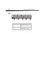
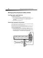
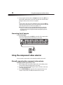
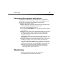
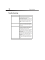
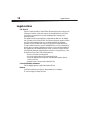
Component Video Selector
DX-CVS4
USE R GUI DE
2
Important safety instructions
Dynex DX-CVS4
Component Video Selector
Contents
Important safety instructions....................................................................2
Component video selector parts................................................................2
Setting up the component video selector..................................................6
Using the component video selector .........................................................8
Maintaining ..............................................................................................9
Troubleshooting......................................................................................10
Specifications..........................................................................................11
Legal notices ...........................................................................................12
One-year limited warranty......................................................................13
Important safety instructions
• For indoor use only.
• No user serviceable parts inside. Do not open the cabinet.
• Use only the provided AC adapter.
Component video selector parts
Features
• Four component video inputs with digital coaxial audio and analog audio inputs
• One component video output with digital coaxial audio and analog audio outputs
• High definition (720p/1080i) compatible
3
Component video selector parts
Package contents
•
•
•
•
•
Component video selector
AC power adapter
Remote control
AAA batteries (2)
User Guide
Front
LEDs for
connected devices
SELECT/LEARN
button
Component
Description
LEDs for connected devices
The LED for a connected device lights when
the device is selected.
SELECT/LEARN button
Press to select a connected component video
device. When a device is selected, the
corresponding LED lights. For more
information, see “Manually operating the
component video selector” on page 8.
Press to program the selector to work with
original equipment remote controls. For
more information, see “Programming the
component video selector” on page 9.
4
Component video selector parts
Back
Pr OUT
Pb
Y
R
L
Pr IN4
Pb
Y
Pr IN3
Pb
Y
Pr IN2
Pb
Y
Pr IN1
Pb
Y
DC 9V
Digital
OUT
Digital
IN4
R
L
Digital
R
IN3
L
Digital
R
L
Digital
IN2
R
L
IN1
Jacks
Description
OUT
Connect a TV to these jacks. For more
information, see “Connecting a TV” on
page 7.
IN1 through IN4
Connect component video devices to these
jacks. For more information, see “Connecting
component video devices” on page 6.
5
Component video selector parts
Remote control
Selects
IN1
Selects
IN2
Selects
IN3
Selects
IN4
6
Setting up the component video selector
Setting up the component video selector
Installing remote control batteries
To install remote control batteries:
1 Remove the battery compartment cover on the back of the remote control.
2 Insert two AAA batteries (included) into the battery compartment. Make sure that the
+ and – symbols on the batteries match the + and – symbols in the battery
compartment.
3 Replace the battery compartment cover.
Connecting component video devices
You can connect up to four component video devices (such as a cable/satellite receiver, DVD
player, or game console) to the component video selector.
The component video selector also has analog and digital (SPDIF) audio connections. Select
the audio connection type that matches the component video device you are connecting.
To connect a component video device:
1 Connect a component video cable to the IN1, IN2, IN3, or IN4 Pr, Pb, and Y jacks on
the back of the component video selector, then connect the other end of the cable to
the component out jacks on the component video device. Make sure that you connect
jacks with matching colors—red to red, blue to blue, and green to green.
Pr OUT
Pb
Y
R
L
Pr IN4
Pb
Y
Pr IN3
Pb
Y
Pr IN2
Pb
Y
Pr IN1
Pb
Y
DC 9V
Digital
Digital
R
L
Digital
R
L
Digital
R
L
OR
Digital
R
L
7
Setting up the component video selector
2 Connect a digital coaxial audio cable to the Digital jack below the video IN jacks on
the back of the component video selector, then connect the other end of the cable to
the digital coaxial audio out jack on the component video device.
Or,
Connect an analog audio cable to the L and R audio jacks below the video IN jacks on
the back of the component video selector, then connect the other end of the cable to
the analog audio out jacks on the component video device.
Connecting a TV
To connect a TV:
1 Connect a component video cable to the OUT Pr, Pb, and Y jacks on the back of the
component video selector, then connect the other end of the cable to the component
video in jacks on the TV.
Pr OUT
Pb
Y
R
L
Pr IN4
Pb
Y
Pr IN3
Pb
Y
Pr IN2
Pb
Y
Pr IN1
Pb
Y
DC 9V
Digital
Digital
OR
R
L
Digital
R
L
Digital
R
L
Digital
R
L
8
Using the component video selector
2 Connect a digital coaxial audio cable to the Digital jack below the video OUT jacks on
the back of the component video selector, then connect the other end of the cable to
the digital coaxial in jack on an A/V receiver or amplifier.
Or,
Connect an analog audio cable to the L and R audio jacks below the video OUT jacks
on the back of the component video selector, then connect the other end of the cable
to the analog audio in jacks on an A/V receiver, amplifier, or TV.
Note: If you are connecting some devices with digital coaxial audio and some with analog
audio, you need to connect both the digital coaxial audio and analog audio out jacks on
the component video selector to the digital coaxial audio and analog audio in jacks on the
audio amplifier or TV.
Connecting the AC adapter
To connect the AC adapter:
• Connect the AC adapter cable to the DC 9V jack on the back of the component video
selector, then connect the other end of the cable to a power outlet.
Pr OUT
Pb
Y
R
L
Pr IN4
Pb
Y
Pr IN3
Pb
Y
Pr IN2
Pb
Y
Pr IN1
Pb
Y
DC 9V
Digital
Digital
R
L
Digital
R
L
Digital
R
L
Digital
R
L
Using the component video selector
You can operate the component video selector manually or with the remote control.
Manually operating the component video selector
To manually operate the component video selector:
1 Make sure that you have connected the component video device and that you have
connected the AC adapter and plugged it into a power outlet.
2 Turn on the component video device using the controls on the device or the remote
control that came with the device.
3 Press the SELECT/LEARN button on the front of the component video selector to
select the connected device. The LED flashes when the device is selected.
9
Maintaining
Programming the component video selector
You can program the component video selector to switch to the correct input when the
connected device is powered on with the remote control that came with that device (or a
universal remote control that has been programmed to operate the device).
To program the component video selector:
1 Make sure that you have connected the component video devices and that you have
connected the AC adapter and plugged it into a power outlet.
2 Turn on the connected component video devices.
3 Press and hold the SELECT/LEARN for four seconds. When the LED labeled 1 flashes
release the button.
4 Within eight seconds, point the remote control that came with the device connected to
the IN1 jacks at the remote control sensor on the front of the component video
selector, then press the power button on the remote control. The LED and the
connected device turn off.
If you do not press a button on the remote control within eight seconds of pressing the
SELECT/LEARN button, the component video selector exits learning mode.
5 Repeat Step 4 using the remote controls that came with the devices connected to the
other IN jacks. For example, use the remote control that came with the device
connected to the IN2 jacks to program that device. Use the remote control that came
with the device connected to the IN3 jacks to program that device. Use the remote
control that came with the device connected to the IN4 jacks to program that device.
Note: If you use a universal remote control to operate all your devices, follow the same
procedure with switching the universal remote control into the mode associated with
each device connected to the component video selector.
Maintaining
• Clean the component video selector with a dust cloth or dry cloth.
• Do not submerge the component video selection in water.
10
Troubleshooting
Troubleshooting
Problem
Solution
No picture
• Make sure the component video selector is set to the
correct input for the device you want to use.
• Make sure that the TV is set to the correct input for the
jacks the selector is connected to.
• Make sure that the TV and device you want to use are
turned on and set to the correct video resolution. The
selector is compatible with 480i, 480p, 720p, and
1080i.
Color is not correct on the TV
• Make sure that the red, green, and blue cable
connectors are connected to the correct inputs and
outputs on the connected device and the component
video selector.
No sound
• Make sure that the TV, A/V receiver, or amplifier
(depending on the method you use for audio playback)
is set to the correct input for the audio jacks the
component video selector is connected to.
• The component video selector does not convert digital
audio to analog audio or analog audio to ditial audio.
Make sure that:
• If you connected a device to the selector with a digital
coaxial audio cable, you must connect the selector to
the TV, A/V receiver, or amplifier with a digital coaxial
audio cable.
• If you connected a device to the selector with an
analog stereo cable, you must connect the selector to
the TV, AV receiver, or amplifier with an analog stereo
cable.
Remote control does not work
• Replace the batteries.
11
Specifications
Specifications
Item
Input
Y
RCA connector 4
Output
U
Digital
audio
V
Analog
audio
4
4
4
R (4), L (4)
Impedance
75 Ω
75 Ω
75 Ω
75 Ω
47 KΩ
Level (Vp-p)
1
0.5
0.5
1.5
1 Vrms
1
1
1
R (1), L (1)
75 Ω
75 Ω
RCA connector 1
Impedance
75 Ω
Level
Input ±10%
Isolation minimum
-50dB
Audio cross talk between
R-ch and L-ch 20Hz-20KHz
45dB(Minimum)
Audio frequency response
20Hz ~ 20KHz
±3dB
75 Ω
47 KΩ
Input ±20%
Input ±10%
Audio THD
0.35% (Input:1Vrms,Output:47Kohm Load)
IR Remote Control
(Average Range)
5m (min) ±15°
Power Supply
Input: AC120V, 60Hz
Output: DC 9V, 200mA
Specifications subject to change without notice.
-45dB
12
Legal notices
Legal notices
FCC Part 15
This device complies with Part 15 of the FCC Rules. Operation of this product is subject to the
following two conditions: (1) this device may not cause harmful interference, and (2) this
device must accept any interference received, including interference that may cause
undesired operation.
This equipment has been tested and found to comply within the limits for a class B digital
device, pursuant to Part 15 of the FCC Rules. These limits are designed to provide reasonable
protection against harmful interference in a residential installation. This equipment
generates, uses, and can radiate radio frequency energy and, if not installed and used in
accordance with the instructions, may cause harmful interference to radio communications.
However, there is no guarantee that interference will not occur in a particular installation. If
this equipment does cause harmful interference to radio or television reception, which can
be determined by turning the equipment off and on, the user is encouraged to try to correct
the interference by one or more of the following measures:
• Reorient or relocate the receiving antenna.
• Increase the separation between the equipment and receiver.
• Connect the equipment into an outlet on a circuit different from that to which the
receiver is connected.
• Consult the dealer or an experienced technician for help.
Canada ICES-003 statement
This Class B digital apparatus complies with Canadian ICES-003.
Notices
Specifications and features are subject to change without notice or obligation.
For service and support call (800) 305-2204.
Legal notices
13
One-year limited warranty
Dynex Products (“Dynex”) warrants to you, the original purchaser of this new DX-CVS4 (“Product”), that the
Product shall be free of defects in the original manufacture of the material or workmanship for a period of one (1)
year from the date of your purchase of the Product (“Warranty Period”). This Product must be purchased from an
authorized dealer of Dynex brand Products and packaged with this warranty statement. This warranty does not
cover refurbished product. If you notify Dynex during the Warranty Period of a defect covered by this warranty
that requires service, terms of this warranty apply.
How long does the coverage last?
The Warranty Period lasts for one year (365 days) from the date you purchased the Product. The purchase date is
printed on the receipt you received with the Product.
What does this warranty cover?
During the Warranty Period, if the original manufacture of the material or workmanship of the Product is
determined to be defective by an authorized Dynex repair center or store personnel, Dynex will (at its sole option):
(1) repair the Product with new or rebuilt parts; or (2) replace the Product at no charge with new or rebuilt
comparable products or parts. Products and parts replaced under this warranty become the property of Dynex
and are not returned to you. If service of products and parts are required after the Warranty Period expires, you
must pay all labor and parts charges. This warranty lasts as long as you own your Dynex Product during the
Warranty Period. Warranty coverage terminates if you sell or otherwise transfer the Product.
How to obtain warranty service?
If you purchased the Product at a retail store location, take your original receipt and the Product to the store you
purchased it from. Make sure that you place the Product in its original packaging or packaging that provides the
same amount of protection as the original packaging. If you purchased the Product from an online web site, mail
your original receipt and the Product to the address listed on the web site. Make sure that you put the Product in
its original packaging or packaging that provides the same amount of protection as the original packaging.
To obtain in-home warranty service for a television with a screen 25 inches or larger, call 1-888-BESTBUY. Call
agents will diagnose and correct the issue over the phone or will have an Dynex-approved repair person
dispatched to your home.
Where is the warranty valid?
This warranty is valid only to the original purchaser of the Product in the United States, Canada, and Mexico.
What does the warranty not cover?
This warranty does not cover:
• Customer instruction
• Installation
• Set up adjustments
• Cosmetic damage
• Damage due to acts of God, such as lightning strikes
• Accident
• Misuse
• Abuse
• Negligence
• Commercial use
• Modification of any part of the Product
• Plasma display panel damaged by static (non-moving) images applied for lengthy periods (burn-in).
14
Legal notices
This warranty also does not cover:
• Damage due to incorrect operation or maintenance
• Connection to an incorrect voltage supply
• Attempted repair by anyone other than a facility authorized by Dynex to service the Product
• Products sold as is or with all faults
• Consumables, such as fuses or batteries
• Products where the factory applied serial number has been altered or removed
REPAIR REPLACEMENT AS PROVIDED UNDER THIS WARRANTY IS YOUR EXCLUSIVE REMEDY. DYNEX SHALL NOT BE
LIABLE FOR ANY INCIDENTAL OR CONSEQUENTIAL DAMAGES FOR THE BREACH OF ANY EXPRESS OR IMPLIED
WARRANTY ON THIS PRODUCT, INCLUDING, BUT NOT LIMITED TO, LOST DATA, LOSS OF USE OF YOUR PRODUCT, LOST
BUSINESS OR LOST PROFITS. DYNEX PRODUCTS MAKES NO OTHER EXPRESS WARRANTIES WITH RESPECT TO THE
PRODUCT, ALL EXPRESS AND IMPLIED WARRANTIES FOR THE PRODUCT, INCLUDING, BUT NOT LIMITED TO, ANY
IMPLIED WARRANTIES OF AND CONDITIONS OF MERCHANTABILITY AND FITNESS FOR A PARTICULAR PURPOSE, ARE
LIMITED IN DURATION TO THE WARRANTY PERIOD SET FORTH ABOVE AND NO WARRANTIES, WHETHER EXPRESS OR
IMPLIED, WILL APPLY AFTER THE WARRANTY PERIOD. SOME STATES, PROVINCES AND JURISDICTIONS DO NOT
ALLOW LIMITATIONS ON HOW LONG AN IMPLIED WARRANTY LASTS, SO THE ABOVE LIMITATION MAY NOT APPLY TO
YOU. THIS WARRANTY GIVES YOU SPECIFIC LEGAL RIGHTS, AND YOU MAY ALSO HAVE OTHER RIGHTS, WHICH VARY
FROM STATE TO STATE OR PROVINCE TO PROVINCE.
Contact Dynex:
For customer service please call 1-800-305-2204
www.dynexproducts.com
Distributed by Best Buy Purchasing, LLC
7601 Penn Avenue South, Richfield, Minnesota, U.S.A. 55423-3645
© 2009 Best Buy Enterprise Services, Inc.
All rights reserved. DYNEX is a trademark of Best Buy Enterprise Services, Inc. Registered in some countries. All
other products and brand names are trademarks of their respective owners.
Legal notices
15
www.dynexproducts.com (800) 305-2204
© 2009 Best Buy Enterprise Services, Inc. All rights reserved.
DYNEX is a trademark of Best Buy Enterprise Services, Inc. Registered in some countries.
All other products and brand names are trademarks of their respective owners.
Distributed by Best Buy Purchasing, LLC
7601 Penn Ave. South, Richfield, MN 55423 U.S.A.
09-0065
ENGLISH