1
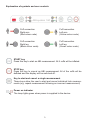
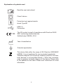
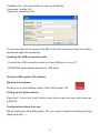
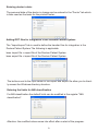
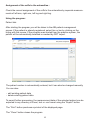
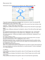
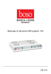
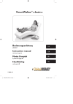
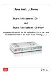
User instructions for the ABI-system 100
0124
User instructions for the ABI-system 100
1
ABI-system 100
2
CA04 cuffs (for upper arms)
2
CL04 cuffs (for legs)
1
ABI-system 100 software
1
USB cable
1
boso mains power supply art. no.: 410-7-154
1
Guarantee certificate
1
User instructions
Software system requirements
• Pentium II or higher
• 256 MB RAM
• Graphics card
• 20 MB hard disk space
• USB interface
• Microsoft Windows® XP, Windows® VistaTM, Windows® 7
2
Explanation of symbols and user controls
Cuff connection
Right arm
(Red colour code)
Cuff connection
Left arm
(Yellow colour code)
Cuff connection
Right leg
(Black colour code)
Cuff connection
Left leg
(Green colour code)
START key
Press this key to start an ABI measurement. All 4 cuffs will be inflated.
STOP key
Press this key to cancel an ABI measurement. All of the cuffs will be
deflated and the display will be switched off.
Key to start and cancel a single measurement
These keys allow the user to start and cancel individual limb measurements (e.g. repeat measurement following an incorrect measurement)
Power on indicator
The lamp lights green when power is supplied to the device.
3
Explanation of symbols used
Read the user instructions!
Class II device
Protection level against electric
shock: Type BF
USB 2.0
Connection
0124
The CE symbol is proof of compliance with Directive 93/42/
EEC concerning medical devices,
Notified body: DEKRA, 0124
Year of manufacture
Potential equalisation
This device falls within the scope of EU Directive 2002/96/EC
(WEEE). It is not registered for use in private households.
Therefore disposal via communal collection points for old electrical devices is not permitted. Bosch + Sohn has commissioned a company to legally dispose of this device. Please refer
to the address on the rear of these user instructions for more
information.
4
Introductory information
Your boso ABI-system 100 is an innovation on the market for blood pressure measurement. It represents an easy way to determine the ankle-brachial index (ABI) and
works according to the oscillometric measurement principle. The pressure variations
(oscillations) caused by the pulse waves and transmitted by the cuffs are saved and
evaluated by the microprocessors. The main advantage of this type of measurement
is that there is no need for a microphone or duplicator whose positioning is crucial
in terms of achieving accurate results.
This device complies with the European directives based on the German Medical
Devices Act (label: CE0124) and with European standard EN 1060, part 1: “Noninvasive sphygmomanometers – general requirements” and part 3: “Supplementary
requirements for electro-mechanical blood pressure measuring systems”.
Technical testing – to be performed every 2 years at the latest – can either be carried
out by the manufacturer, or the authorities or persons responsible for metrology, all
of which must meet the requirements of the Medical Devices Operator Ordinance
§ 6. Technical testing instructions can be found on page 23 of these user
instructions.
Electrical medical devices are subject to specific precautionary measures with regard
to electromagnetic compatibility, and must therefore be installed and operated according to the Electronic Compatibility Act information listed on pages 24 and 25.
Important information:
• The same exclusion criteria apply for the oscillometric ABI measurement as for
the Doppler measurement.
• The device must never be used on patients with serious heart failure.
• On unconscious, helpless, dazed or confused persons the instrument is not be
used unattended.
• The cuffs must never be placed on open wounds.
• The cuffs must never be placed on implanted stents.
• The cuffs must never be placed on lymphoedemas.
• There must be a period of at least 2 minutes between 2 consecutive
measurements.
• Irregular heart rate defects can interfere with the accuracy of a measurement or lead to incorrect readings. Interference can also occur among people with pace
makers who have a weak pulse. The sphygmomanometer will have no effect on
the pacemaker, however.
• Pregnant women, diabetics and people with liver problems may experience
distorted readings.
• Operating the device in the vicinity of strong electromagnetic fields (e.g. radiation
appliances, mobile phones) may lead to malfunction (see pages 24 and 25).
5
• The computer used to evaluate the readings must meet the requirements set out
in EN 60601-1.
• The instrument can only be operated together with the enclosed software.
ABI
The systolic blood pressure values of a person’s arms and legs need to be measured in order to determine the ABI value. The blood pressure measurements are
stated in mmHg.
The ankle-brachial index (ABI) is calculated as a quotient of the systolic pressure
from the leg measurement (the higher pressure in A. tibialis posterior and A. tibialis anterior¹) and the higher systolic pressure from the arm measurements.
Turning the device on
The connection sockets for the mains power supply are located on the rear of the
device. Only use the boso mains power supply (order no. 410-7-154) as it provides a constant power supply, is perfectly synchronised and correctly polarised.
Standard commercial mains power supplies may damage the electronics and lead
to invalidation of the factory warranty.
Installing the ABI system 100 software
After inserting the “ABI system 100” CD, a menu window will appear with the option of installing the software as a single user version or network version.
Installing the single user version
Click the button “Installiere ABI-Software” under “Einzelplatzversion” and follow
the instructions displayed on the screen.
¹ Deutsches Ärzteblatt | Jg. 102 | Heft 34-35 | 29. August 2005 | Knöchel-Arm-Index | C. Diehm, H. Darius, D. Pittrow, J. Allenberg
6
Installing the network version
Firstly you need to install the Firebird database server locally on the server by
clicking the button “Installiere Firebird DB-Server” (this step is not required if a
Firebird server is already running on this system).
Then install the database file “ABI.fdb” locally on the server in a directory of your
choice by clicking the button “Installiere Datenbankdatei”.
Then install the ABI software on each required workstation PC by clicking the button “Installiere ABI-Software”.
Note:
You need to reboot the computer when the installation is complete.
After starting the ABI software for the first time when installed as a network version, the user will be prompted to enter access data (this will only occur the first
time the software is started).
The access data include:
Server name: Your server’s computer name in the network
7
Database File: The target folder for the server\ABI.fdb
Username: sysdba (fix)
Password: masterkey (fix)
The access data will be saved in the ABI.ini file; this information does not need to
be entered again during startup.
Installing the USB connection cable
• Connect the USB connection cable to a free USB port on your PC.
• WINDOWS automatically detects the USB-cable
Using the ABI system 100 software
Starting the program:
Double click on the desktop symbol “Boso ABI system 100”
Calling up the help function:
Press the F1 key or the “Help” button at any time to open the user instructions as
a PDF file.
Configuration before first use:
Before starting the boso ABI system 100, you need to make the following settings
(Settings button…):
8
Entering doctor’s data:
The personal data of the doctor in charge can be entered in the “Doctor” tab which
is then used as the basis for the printout footer:
Adding GDT files for integration in the Doctors Patient System:
The “Import/export” tab is used to define the transfer files for integration in the
Doctors Patient System.The following is applicable:
boso import file = export file of the Doctors Patient System
boso export file = import file of the Doctors Patient System
The buttons next to the input fields for the import and export file allow you to directly access the Windows directory structure.
Entering the limits for ABI-classification
For ABI-classification the default limits can be modified in the register "ABIclassification".
Attention: the modified values come into effect after re-start of the program.
9
Assignment of the cuffs to the extremities.:
Check the correct assignment of the cuffs to the extremities by seperate measurements of left arm, right arm, left leg and right leg.
Using the program:
Patient tab:
After starting the program you will be taken to the ABI patient management
screen. If the patient is already registered, select him or her by clicking on the
listing with the mouse. If the program was started from the practice system, the
patient will be automatically selected or created by GDT import.
The patient number is automatically entered, but it can also be changed manually.
You can also:
- edit existing patient data
- delete existing patient data
To permit further processing, the measurement data of the selected patient can be
exported to any directory in Excel, text or .csv format using the “Export” button.
The “Print” button produces a printout of the displayed page.
The “Close” button closes the program.
10
Measurement tab:
Performed measurements can be viewed in the “Measurements” tab.
If several measurements have already been carried out, select the desired ABI
measurement in the “Date-time” field.
The following parameters will be displayed on the screen from top to bottom (two
columns – one for each side of the body):
DiffSys Arm (difference between the systolic values of the left and the right upper
arm)
DiffDia Arm (difference between the diastolic values of the left and the right upper
arm)
Sys (systolic blood pressure of the upper arm), displayed in red > 140 mmHg
Dia (diastolic blood pressure of the upper arm), displayed in red> 90 mmHg
PP (pulse pressure = difference between systole and diastole), displayed in red
>54 mmHg
Pul (pulse value) in 1/min.
Arr (indicates whether a pulse frequence anomaly of more than 25% occurred
during a measurement (“Yes”, displayed in red, or “No”).
ABI (ankle-brachial index = quotient from the leg measurement’s systolic value
divided by the higher systolic value from both upper arm measurements), by default displayed in red < 0.9.
Sys (ankle systolic blood pressure)
Note: If no measurement result is displayed for the ankle’s systolic blood pressure,
this may indicate a circulatory disturbance or media sclerosis. Further investigation is recommended.
In addition:
Δ Sys (difference between the systolic value of the left upper arm and the right
upper arm).
Δ Dia (difference between the diastolic value of the left upper arm and the right
upper arm).
Δ Sys (difference between the systolic value of the left and the right ankle)
11
Click on one of the oscillation profiles to enlarge the view of the selected profile.
The “Pulse level over time” tab shows the oscillation curve over the time axis.
The “Pulse level over cuff pressure” shows the oscillation curve over the cuff pressure.
“Profiles” tab:
The ABI values of all measurements are displayed as graphs in the “Profiles” tab.
The blue bar represents the ABI value of the first measurement, the red bar the
ABI value of the second measurement.
The colour display corresponds to the setting in “ABI Evaluation” (red: ABI < 0.9).
12
Preparing for a measurement
The measurement must be performed on a patient who is lying down in order ensure
equal blood pressure among all limbs.
The patient should lie down for approx. 5 minutes before taking a measurement.
Fixing the cuff
The cuffs are colour coded. Affix the cuffs on both upper arms and both ankles
according to their colour coding (matching the symbols next to the air connection
sockets on the device).
The upper arm cuffs should be affixed in such a way that the lower edge of the cuff
is approx. 2-3 cm above the elbow joint. The marking on the cuff should be on the
arteria brachialis.
The metal ring should never be affixed over the arteries, as this may lead to incorrect
measurement values.
The ankle cuffs should be affixed in such a way that the lower edge of the cuff is
approx. 1-2 cm above the ankle. The marking on the cuff should be on the arteria
tibialis. Make sure that the cuff is tightly affixed to the ankle.
The device should only be used with original boso cuffs CA04 or CL04.
Type
Circumference
Order no.
CA04
22 - 42 cm
143 - 4 - 768
CL04
18 - 38 cm
143 - 4 - 769
13
Taking a measurement
In order to add a new patient in the ABI software, select the “New” button in the
“Patient” tab. “Name” and “Patient no.” are obligatory fields.
Select “NStart new measurement” in the “Measurements” tab or press the START
button on the device. The ABI-system 100 starts the ABI measurement after a short
calibration procedure (approx. 3 seconds).
Press the START key on the ABI-system 100. After about 3 seconds all of the
number segments will appear briefly in the display in order to permit a full functionality check.
The device has intelligent automatic inflation technology to ensure comfortable
inflation and the correct cuff pressure. The increasing cuff pressure will be displayed
digitally.
When the correct inflation pressure has been reached, the pump will switch off and
cuffs will deflate automatically.
14
The decreasing cuff pressure will be displayed during the measuring phase. By
this time (at the latest) all four limbs have to be kept absolutely still and the patient
must not talk.
Once the measurement has finished, the integrated valves will open automatically
to quickly deflate the cuffs.
The measured values are displayed in the ABI software.
The measurement will be displayed on the screen
and so the user can check the measurement, and
it is automatically transferred to the ABI software.
Systole (mmHg)
Diastole (mmHg)
A remark can be added to each ABI-measurement by using the button "Remarks".
15
Repeating a measurement
In order to repeat a measurement, press the START key on the ABI-system 100
again. The previous measurement will be overwritten.
In order to perform a measurement on one limb, press the Start new measurement”
button again.
However it is recommended to perform all measurements at the same time.
If no other measurement is required, remove all of the cuffs from the limbs.
The current measurement results will be displayed until the device is turned off by
pressing the STOP key.
Saving a measurement:
Click on the button “Save measurement" to save a measurement in the ABI software.
Performing a second measurement
The screen for performing a second measurement will appear. If you want to end
the set of measurements after the first ABI measurement, press the “Back” button
(not recommended).
If all of the values were correctly displayed after carrying out the second set of
measurements, click the button “Save measurement” and then “Back”. You will
return to the “Measurements” tab.
16
The times above the measurement value columns indicate the time of measurement
(1st and 2nd measurement).
Cancelling a measurement
A measurement can be cancelled at any time by clicking the “Cancel measurement”
button in the software or pressing the STOP key on the device, which in turn automatically deflates all of the cuffs. Alternatively, the cuffs can be removed from the
limbs at any time.
Cleaning the device and cuffs
Please only use a soft, dry cloth to clean the device.
Small marks or stains on the cuffs can be carefully removed with a damp cloth.
Disinfecting the device
We recommend the disinfectant Antifect® Liquid (Schülke&Mayr) to wipe and
thus disinfect the device.
Guarantee, customer service
Please refer to the guarantee certificate for the terms of guarantee.
Guarantee claims will only be acknowledged if the device is sent together with the
guarantee certificate completed and signed by the dealer.
For guarantee and repair work, please carefully pack the device and send it (with
sufficient postage) to your authorised dealer or directly to:
BOSCH + SOHN GmbH u. Co. KG
Fabrik mediz. Apparate
Bahnhofstraße 64
D-72417 Jungingen
17
Technical data
Measurement method: oscillometric
Measurement range: 40 – 240 mmHg
Cuff pressure: 0 – 300 mmHg
Display: LCD
Operating conditions:
Ambient temperature 10°C to 40°C
Rel. humidity 10 to 85%
Transport and storage conditions:
Ambient temperature -5°C to + 50°C
Rel. humidity max. 85%
Power supply:
Mains power supply DC 5V, AC 100-240V, 50-60 Hz, 2700mA, order no.: 410 – 7
– 154
(Polarity: outer MINUS, inner PLUS)
Weight: 3.68 kg without mains power supply
Dimensions (W x H x D):
458 mm x 83 mm x 290 mm
Classification: Class II (symbol:
Type BF (symbol:
)
)
Clinical test (DIN 58130):
The measuring precision complies with the requirements of EN 1060 part 3
Maximum tolerance in cuff measurement: ± 3 mmHg
Technical specifications subject to change without prior notification.
18
Technical testing procedure
A) Function testing
Function testing of the device can only be performed on human subjects or using
a suitable simulator.
B) Leak testing of the pressure circuit and display error testing
Note: If the pressure during measuring mode increases to more than 320 mmHg,
the quick deflate valve will be activated and the pressure circuit will be opened.
The measurement value display will also blink if the pressure exceeds 320 mmHg
when in test mode.
Testing:
1.)
"to open “Test mode” in the “Patient” tab and press the “Start” button.
2.)
Aftera short calibration procedure, the device will be in test mode.
The current pressure will be displayed in the fields (this value will be zero
if there is no pressure).
3.)
Perform the usual tolerance testing of the pressure display and leak
testing of the pressure circuit (take account of the cuff’s minimum settling
time of 30 seconds).
4.)
Run test for all four extremities.
5.)
Exit test by pressing the “End test” button.
C) Safety
For safety purposes the two halves of the device can be joined together with a
safety seal.
19
EMC-notes for your ABI-system 100
Medical Electrical Equipment needs special precautions regarding EMC and needs to be installed and put into service according the EMC information provided in the following.
Portable and mobile RF communication equipment (e.g. cell phones) can affect Medical Electrical Equipment.
The use of accessories and cables other than those specified (other than boso original parts) may result in increased emissions or decreased immunity of the unit.
Guidance and manufacturer’s declaration – electromagnetic emissions
The boso unit is intended for use in the electromagnetic environment specified below. The customer of the user of the boso unit should
assure that it is used in such an environment.
Emissions test
Compliance
Electromagnetic environment – guidance
RF emissions
CISPR 11
Group 1
The boso unit uses RF energy only for its internal function. Therefore, its RF emissions are very low and are not likely to cause any
interference in nearby electronic equipment.
RF emissions
CISPR 11
Class B
Harmonic emissions
IEC 61000-3-2
Class A
The boso unit is suitable for use in all establishments, including
domestic establishments and those directly connected to the public
low-voltage power supply network that supplies buildings used for
domestic purposes.
Voltage fluctuations/flicker
emissions IEC 61000-3-3
Complies
Guidance and manufacturer’s declaration – electromagnetic immunity
The boso unit is intended for use in the electromagnetic environment specified below. The customer or the user of the boso unit should
assure that it is used in such an environment.
Immunity
test
IEC 60601
test level
Compliance level
Electrostatic
discharge (ESD)
IEC 61000-4-2
± 6 kV
contact
± 6 kV
contact
± 8 kV
air
± 8 kV
air
Electrical fast
transient/burst
IEC 61000-4-4
± 2 kV for power
supply lines
± 2 kV for power
supply lines
± 1 kV
for input/output
lines
± 1 kV
for input/output
lines
Surge
IEC 61000-4-5
± 1 kV
differential mode
± 1 kV
differential mode
±2 kV
common mode
±2 kV
common mode
< 5% UT
(> 95% dip in UT)
for 0,5 cycle
< 5% UT
(> 95% dip in UT)
for 0,5 cycle
40% UT
(60% dip in UT)
for 5 cycles
40% UT
(60% dip in UT)
for 5 cycles
70% UT
(30% dip in UT)
for 25 cycles
70% UT
(30% dip in UT)
for 25 cycles
< 5% UT
(> 95% dip in UT)
for 5 s
< 5% UT
(> 95% dip in UT)
for 5 s
3 A/m
3 A/m
Voltage dips,
short interruptions and
voltage variations
on power supply
input lines
IEC 61000-4-11
Power frequency
(50/60 Hz)
magnetic field
IEC 61000-4-8
Electromagnetic environment – guidance
Floors should be wood, concrete or ceramic tile.
If floors are covered with synthetic material, the
relative humidity should be at least 30%.
Mains power quality should be that of a typical commercial or hospital environment.
Mains power quality should be that of a typical commercial or hospital environment.
Mains power quality should be that of a typical commercial or hospital environment. If the user of the boso
unit requires continued operation during power mains
interruptions, it is recommended that the boso unit has
to be powered from a uninterruptible power supply or a
battery.
NOTE : UT is the a.c. mains voltage prior to application of the test level.
20
Guidance and manufacturer’s declaration – electromagnetic immunity
The boso unit is intended for use in the electromagnetic environment specified below. The customer or the user of the boso unit should
assure that it is used in such an environment.
Immunity
test
IEC 60601
test level
Compliance level
Electromagnetic environment – guidance
Portable and mobile RF communications equipment should be used no closer to any party of the
boso unit, including cables, than the recommended
separation distance calculated from the equation
applicable to the frequency of the transmitter.
Recommended separation distance:
Conducted RF
IEC 61000-4-6
3 V rms
150 kHz to 80 MHz
3 V rms
d = 1,2
Radiated RF
IEC 61000-4-3
3 V/m
80 MHz to 2,5 GHz
3 V/m
d = 1,2 P
80 MHz to 800 MHz
d = 2,3
800 MHz to 2,5 GHz
P
P
where P is the maximum output power rating of the
transmitter in watts (W) according to the transmitter
manufacturer and d is the recommended separation distance in metres (m).
Field strengths from fixed RF transmitters, as determined by an electromagnetic site survey, a should
be less than the compliance level in each frequency
range.b
Interference may occur in the vicinity of
equipment marked with the following
symbol:
NOTE 1 At 80 MHz and 800 MHz, the higher frequency range applies.
NOTE 2 These guidelines may not apply in all situations. Electromagnetic propagation is affected by absorption and reflection from
structures, objects and people.
a
Field strengths from fixed transmitters, such as base stations for radio (cellular/cordless) telephones and land mobile radios, amateur
radio, AM and FM radio broadcast and TV broadcast cannot be predicted theoretically with accuracy. To assess the electromagnetic
environment due to fixed RF transmitters, an electromagnetic site survey should be considered. If the measured field strength in the
location in which the boso unit is used exceeds the applicable RF compliance level above, the boso unit should be observed to verify
normal operation. If abnormal performance is observed, additional measures may be necessary, such als re-orienting or relocating the
boso unit.
b
Over the frequency range 150 kHz to 80 MHz, field strengths should be less than 3 V/m.
Recommended separation distances between portable and mobile RF communications equipment and the boso unit
The boso unit is intended for use in an electromagnetic environment in which radiated RF disturbances are controlled. The customer or the
user of the boso unit can help prevent electromagnetic interference by maintaining a minimum distance between portable and mobile RF
communications equipment (transmitters) and the boso unit as recommended below, according the the maximum output power of the communications equipment.
Separation distance according to frequency of transmitter
m
Rated maximum output
power of transmitter
W
150 kHz to 80 MHz
80 MHz to 800 MHz
800 MHz to 2,5 GHz
0,01
0,1
1
10
100
d = 1,2 P
0,12
0,38
1,2
3,8
12
d = 1,2 P
0,12
0,38
1,2
3,8
12
d = 2,3 P
0,23
0,73
2,3
7,3
23
For transmitter rated at a maximum output power not listed above, the recommended separation distance d in metres (m) can be estimated
using the equation applicable to the frequency of the transmitter, where p is the maximum output power rating of the transmitter in watts
(W) according the the transmitter manufacturer.
NOTE 1 At 80 MHz and 800 MHz, the separation distance for the higher frequency range applies.
NOTE 2 These guidelines may not apply in all situations. Electromagnetic propagation is affected by absorption and reflection from structures, objects and people.
21
Your notes:
22
Your notes:
23
Subject to change without prior notification. Omissions and errors
excepted. (09/2008)
BOSCH + SOHN GmbH u. Co. KG
Bahnhofstraße 64 • 72417 Jungingen • Germany
Phone: +49 (74 77) 92 75-0 • Fax: +49 (74 77) 10 21
Internet: www.boso.de • e-Mail: [email protected]