1
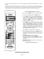
When three channels have been focused, cover the blue lens
with the lens cap and use the menu system to call up the Red
Convergence pattern. You may reach this menu by pressing
“Menu” to reach the Main Menu, “8” to reach the “Adjust”
menu, “4” to reach the main “Convergence” menu and finally,
“1” to reach the red convergence.
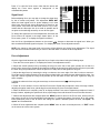
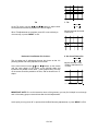
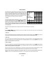
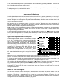
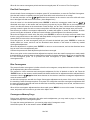
To proceed with the alignment, loosen the two screws at the
top of the red tube and the screw on the floor pan of the
projector as shown in the diagram on this page.
B
B
B
R
R
R
Refer to the diagram for the exact location of the three screws. The screws for the Red tube are marked on the
diagram with an “R” and the screws for the Blue tube are marked with a “B”. You may need to use a flashlight to
locate the screw that connects the tube assembly to the floor pan.
IMPORTANT NOTE: Make certain that you locate the base screw closest to the red or blue tube. DO NOT loosen
the screws that secure the green tube. LOOSEN THE SCREWS ONLY, DO NOT remove them.
When the screws have been loosened, use two hands to gently move the red tube/lens assembly so that the red
lines precisely cover the green reference at the center of the screen. IT is more important to achieve center
coverage here; any variations at the outer edges of the picture may be corrected during setup with the geometry
and convergence controls.
Once the best center convergence is achieved, tighten all three screws.
Press “2” to call up the Blue Convergence grid and repeat the procedure outlined above, this time loosening the
three screws that secure the blue tube/lens assembly and move the tube to achieve best coverage of the red
lines with the blue channel. Be certain to tighten the screws when you are finished.
Press “MENU” three times or “EXIT” to exit the menu system.
The unit is now aligned for the new screen size, and you should proceed with all normal setup
instructions detailed in this manual.
28 of 29