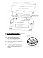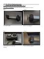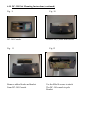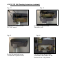
1
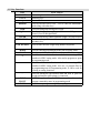
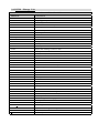
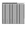
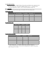
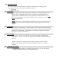
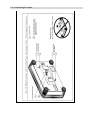
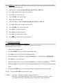
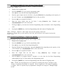
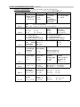
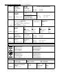
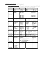
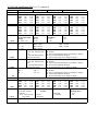
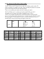
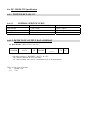
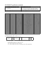
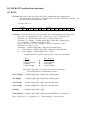
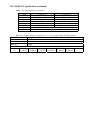
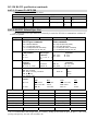
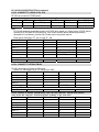
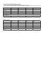
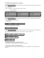
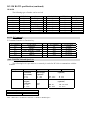
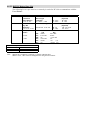
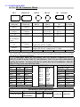
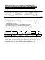
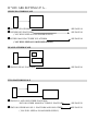
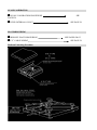
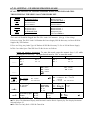
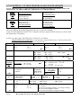
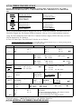
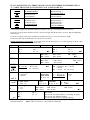
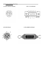
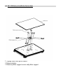
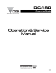
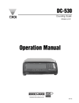
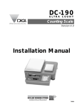
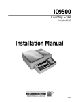
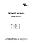
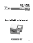
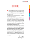
DC-190
Counting Scale
When Accuracy Counts
Operation Manual
73352
DC-190 SERIES OPERATING MANUAL
SECTION
1.0
INDEX
GENERAL
1.1.
1.2.
1.3.
1.4.
1.5.
1.6.
1.7.
2.0
PAGE NUMBER
5-10
Description
Appearance
Keyboard & Display Layout
Indicator Lamp Information
Key Switch Information
DC-190 Message List
DC-190 Character Code List (Teraoka Code)
SPECIFICATIONS
5
6
6
7
8
9
10
11
2.1 Capacities
3.0
INSTALLATION
3.1
3.2
3.3
3.4
4.0
11
12
Un-packing
Inspection
Re-packing
Un-locking Procedure
DC-190 OPERATIONAL PROCEDURES
4.1. Tare Reduction
4,1,1, One Touch Tare
4.1.2. Digital Tare
4.2. Net / Gross
4.3. Unit Weight
4.3.1. Unit Weight by Sampling
4.3.2. Unit Weight by Key Entry
4.4. Accumulation
4.5. Subtraction / Reduction
4.6. Clearing of Accumulated Data
4.7. Clearing Unit Weight
4.8. Scale 1 ←→ 4 Operation
4.9. Recall Item From Memory:
4.10. Re-computing Unit Weight in Memory
4.11. To Set New Item Code in Normal Operation
4.12. Inventory Operation
12
12
12
12-13
14-18
14
14
14
14
14-15
14
15
15
16
16
16
17
17
17
18
18
SECTION
5.0.
INDEX
PAGE NUMBER
PROGRAM MODE
19-23
5.1. Data setting Programming Id Code (200 Item Memory)
5.2. Set Point Programming
5.2.1. Set Point Programming by Quantity %
5.2.2. Set Point Programming by Weight %
5.2.3. Set Point Programming by Upper & Lower Limit Quantity
5.2.4. Set Point Programming by Upper & Lower Limit Weight
5.2.5. Set Point Programming by Weight or by Quantity
5.3. Check Item Code in Memory
5.4. Delete Item Memory
5.5. Check/Set Time and Date
6.0.
MAINTENANCE MODE
6.1. Scale Calibration
6.2. Internal Count Display
6.3. Spec Setting 1 - 4 -1
6.4. Spec Setting 1 - 4 -2
6.5. Spec List
6.6. RS – 232 Specification
6.7. Connector Matrix, Setting – Up, Platform Wiring, Pin Outs, & Y Cable
6.8. DC-190 AC / Battery Operation
6.9. DC-190 Assembly Procedure
6.10. DC-190 Pole Mounting Instructions
6.11. Shop Notes
6.12. Bar Code Board
!See pages 24,42 & 43 for revisions in this manual
19-20
20-22
20
21
21
22
22
23
23
23
24-68
24
24
25
25
26-29
30-41
42-54
55-57
58
59-63
64
65-66
1.0.
GENERAL
1.1. Description
The DC-190 counting scale offers a practical solution to a full range of
precision counting applications. There are a variety of models available
ranging from a weight capacity of 0.5 lb. through 100 lb. utilizing an
internally mounted load cell and a full range of capacities from 0.5 to 50,000
lb. utilizing external second and third platform. A console model is also
available with 3 external platforms in any of the above mentioned capacities
in any combination. An ultra-high resolution force balance scale may also
be used as a sample scale.
This manual will provide the user with information necessary to operate and
program the DC-190. Included in this manual are descriptions, specifications,
operating instructions and service guide.
1.2. Appearance
1.3. Keyboard & Display Layout
1.4. Indicator Lamps
LAMP
“ON”
Zero
Tare
Gross
Insuff
When the gross weight is zero.
When tare weight is set.
When [Gross/Net] key is pressed.
When the net weight is below a specific percentage of capacity
weight.
When unit weight recomputing is possible.
When quantity is being accumulated or when memory overflows.
When in the programming mode with [MODE] key pressed.
When the item is weighed in Kg unit with [Kg/Lb] key pressed.
When the Item is weighed in Lb unit with [Kg/Lb] key pressed.
When battery’s power level is low.
When Scale 1 is used.
When Scale 2 is used
When Scale 3 is used.
When Scale 4 is used.
Inventory In
Inventory Out
Recomp
Memory
Prog
Kg
Lb
Batt
Scale 1
Scale 2
Scale 3
Scale 4
IN
OUT
1.5. Key Functions
KEY
ON/OFF
0 TO 9
.
REZERO
TARE
Kg/Lb
CLEAR
NET/GROSS
UNIT WEIGHT
MODE
SCALE
+
−
*
CODE
IN/OUT
PIECES
FUNCTIONS
For turning the machine ON and OFF.
Numeric Keys.
Decimal Point.
Used to reset the scale to zero. Used to enter the maintenance
mode along with other keys
Used for setting and clearing tare weight.
Used to change the weighing unit between Kilogram and
Pound. (Used in Weight Mode)
Used to clear the key entries and unit weight. (See Spc 6 Bit 2)
Used to change between Gross and Net. Also used as
inventory key
Used to enter the unit weight using numeric keyboard.
Used for entering programming mode from weighing mode.
Used to switch between different scales
Used for Accumulation function and for incrementing SPEC
numbers in SPEC setting mode. Also used to program set point
in programming mode
Used for Subtraction function and for decrementing SPEC
numbers in SPEC setting mode. Also use to program Part No
in programming item. In Programming mode , it can be used for
viewing or setting date/time.
Used for storing the specification data and used to print out
weight information when printer is connected.
[CODE] key, for calling out ITEM memory data. Also used to
program commodity name in programming mode
Used for computing unit weight by sampling.
1.6. DC190
Message List
DC190
MESSAGE LIST
MESSAGE
CONTENTS
ACC
---Add
XX
ALL
C
XX
CH
XXX
ALL CLEAr
dFt SPC
EntEr tIñE
EntEr y-ñ-d
Fb
Coñ Err
FrI
FULL
InVEnt
Lo-Err
ñon
ñon-SUn
0-6
not F
OF
P-nAñE
P-no
PrESS CodE
ProG
P-SP
rS232 Coñ Err
S-on
Sat
SEt P
SEt X
SPCXX
SUn
TArE
tArE oFF LoAd
t-C XX
XX – XX
THU
totAL XXXXXXX
TUE
UF
UnIt u
UP-Err
VEr X.XX
UED
Accuracy
Sampling quantity is Insufficient
All Memory
Number of Items in Memory
Checking Item Code
Clear Memory
Default Spec
Enter Time from 0000 to 2400
Enter Year Month and Date
Force Balance Communication Error
Friday
Memory Full
Inventory
Span Is Out Of Range (on the low side)
Monday
Mon=0, Tue=1, Wed=2,Thu=3,Fri=4,Sat=5,Sun=6
Item Not Found
Overflow
Part Name
Part No
Calibration Mode : Press Code Key to auto find Zero Number
Programming Mode
Item Set Point
RS232 Communication Error (PC/Printer)
Span Switch is On
Saturday
Set Point
Set Point Number
Spec Number
Sunday
Tare
Tare Is Not Allowed Since Weight >0
Teraoka Code | Character Position | Character Code - Character
Thursday
Accumulating or Subtracting Operation
Tuesday
Underflow
Unit Weight
Span Is Out Of Range (on the high side)
Version Number
Wednesday
1.7. DC190 CHARACTER CODE LIST (TERAOKA CODE)
CODE
CHARACTER
CODE
CHARACTER
CODE
CHARACTER
00
SPACE
20
T
40
@
01
A
21
U
41
!
02
B
22
V
42
''
03
C
23
W
43
#
04
D
24
X
44
$
05
E
25
Y
45
%
06
F
26
Z
46
&
07
G
27
,
47
/
08
H
28
.
48
(
09
I
29
-
49
)
10
J
30
0
50
‘
11
K
31
1
12
L
32
2
13
M
33
3
14
N
34
4
15
O
35
5
16
P
36
6
17
Q
37
7
18
R
38
8
19
S
39
9
2.0. SPECIFICATIONS
This section includes a detailed listing of all pertinent specifications and parameters for the
DC-190 counting scales. The system weighing accuracy is 0.02 % . All models meet or
exceed the requirements of OIML, Class III, and NIST Handbook, Number 44.
2.1.
Capacities
The following resolution specifications apply to all models of DC-190 counting scales:
Dc-190 Single Scale
Capacity
Mounting
Internal/External
Both
Both
Both
Both
Both
Both
Both
Both
0.5 lb.
1.0 lb.
2.5 lb.
5.0 lb.
10.0 lb.
25.0 lb.
50.0 lb.
100.0 lb.
Weight
Resolution
0.00005
0.0001
0.0002
0.0005
0.001
0.002
0.005
0.01
Counting
Resolution
0.0000005
0.000001
0.000002
0.000005
0.00001
0.00002
0.00005
0.0001
Platform Dimension
6” x 8”
6” x 8”
7” x 10”
12” x 14”
12” x 14”
12” x 14”
12” x 14”
12” x 14”
DC-192D Dual Scale
Capacity
Scale 1 Scale 2
0.5000
5.0000
1.0000
5.0000
1.0000
10.000
1.0000
25.000
1.0000
50.000
2.5000
10.000
2.5000
25.000
2.5000
50.000
Sample
Platform
4” x 6”
4” x 6”
4” x 6”
4” x 6”
4” x 6”
4” x 6”
4” x 6”
4” x 6”
Bulk
Platform
9” x 12”
9” x 12”
9” x 12”
9” x 12”
9” x 12”
9” x 12”
9” x 12”
9” x 12”
Dc-192l Remote Platforms
Platform capacity
250.00
500.00
1000.0
2500.0
5000.0
10000
25000
50000
Weight
Resolution
0.02
0.05
0.1
0.2
0.5
1.0
2.0
5.0
Counting
Resolution
0.0002
0.0005
0.001
0.002
0.005
0.01
0.02
0.05
Platform
Dimensions
17” x 21”
**
17” x 21”
**
24” x 28”
**
36” x 36” or 48” x 48”
48” x 48”
**
48” x 48” or 60” x 60”
48” x 72” or 60” x 84”
60” x 84”
**
**
**
**
** Other platform sizes are available; consult factory for more information.
* Units are selectable from lb. to kg. and can be programmed to weigh in other primary
Units ; lb., kg., g., oz., or dwt.
3.0. INSTALLATION
This section provides the information required for installing this counting system
for operation. The following steps accomplish installation.
1. Unpacking
2. Set-up Procedure
3.1. Unpacking
Each component of the DC-190 system is packed in a specially designed carton.
Remove each component from its carton, separate the component from its
polystyrene shell assembly and set aside. Inspect the carton interior to be sure
that all accessories have been removed from the carton. Inspect the carton inner
panels for accessories.
NOTE: Be sure to repack all materials within the carton set. Store the cartons in
A secure area so they can be available whenever future shipment of the scale is
required.
3.2. Inspection
Immediately after unpacking, a visual inspection of the scale should be performed.
If any damage has been incurred during transportation notify the shipper and DIGI
MATEX, Inc. immediately. Instructions for assessment of damage and further
procedures will then be determined.
3.3. Repackaging
If, at anytime, the DC-190 counting scale must be returned for modification,
calibration, or repair, be sure that it is properly packed with sufficient cushioning
materials.
Whenever possible, the original carton assembly should be retained for this
purpose. Any damage caused by improper packaging will not be covered by
warranty.
3.4. Unlocking Procedure
The unlocking procedure is included on the next page. The DC-190 should
be properly locked whenever it is being transported.
3.4. Sx Unlocking Procedure
4.0 OPERATION GUIDE IN WEIGHING MODE
4.1
4.1.1
Tare Reduction :
One Touch Tare Operation :
All weights listed in these instructions are for example only use smaller weights for lower capacity
scales!
1 Display in the weighing mode
2
Place 0.5 Lb weight on the platter. (Example : of a .5lb tare)
3
Press the [TARE] key to tare the weight on the platter
4
Remove the weight from the platter
4.1.2. Digital Tare Operation :
1
Display in the weighing mode.
2
Enter [0][.][5][0][0][0] (Example : of a .5lb tare)
3
Press the [TARE] key to tare the weight entered by keyboard.
4.2
Net/Gross Operation :
1
Display in the weighing mode.
2
Place 0.5 Lb. weight on the platter.
3
Press the [TARE] key to tare the weight on the platter.
4
Place an additional 0.5 Lb. on the platter.
5
Press the [NET / GROSS] key. 1.0000 lb is the Gross Weight.
6
Press the [NET / GROSS] key. 0.5000 lb is the Net Weight.
4.3
Unit Weight Operation :
4.3.1 Unit Weight Operation by Sampling :
1
Display in the weighing mode
2
Place 10 pcs of the item to be sampled on the platter.
3
Press the [PIECES] key. Please wait for a few seconds for the computation.
4
The Unit Weight Display shows the Unit Weight of the samples (1.255/1000 pieces) and the
Quantity Display shows the Quantity of the pieces i.e. 10 in this case.
Note : If the insufficient lamp is “ON”, when the sample pieces are placed on the platter, add a few
more pieces until the Insufficient lamp is “OFF. Enter the no. of pieces using the keyboard and press the
[PIECES] key. For example : After putting ten pcs. on the scale as a sample, if the insufficient lamp is
“ON”, add a few more pieces (ex. 3) until the insufficient lamp is “OFF”. Now using the keyboard,
enter [1][3] and then press the [PIECES] key to compute the unit weight of the samples.
4.3.2. Unit Weight Operation by Key Entry :
already known.
This following procedure is used if the unit weight is
1
Display in the weighing mode
2
Enter the known Unit Weight using the keyboard. [2][.][8][7]
3
Press the [UNIT WEIGHT] key to enter the unit weight.
4
Place 2 lb weight on the platter. The scale displays the quantity for the weight placed on the
platter. (A 2 lb. weight is used as an example only.)
4.4. Accumulation Operation When Spec 32 bit 1, Default Setting, (Auto Exit when Accumulation) is
enabled, The Scale will automatically go back to weight mode after the Accumulation.
1
After Unit Weight entry. (See 4.3)
2
+] key. The Total is displayed in the Quantity Display.
Press the [+
3
The memory lamp will glow. After a moment the scale will resume operation mode.
4
Put 1.0lb on the platter
5
+] key. The Total is displayed in the Quantity Display.
Press the [+
6
The memory lamp will glow. After a moment the scale will resume operation mode.
7
The previous total of 25 and the present quantity of 15 are added and the Total Of 40 is
displayed in the Quantity Display.
8
The memory lamp will glow. After a moment the scale will resume operation mode.
9
+] key makes the total 15 + 40 = 55, displayed in the Quantity Display.
Pressing the [+
4.5. Subtraction/Reduction Operation : When Spec32 bit1 (Auto Exit From Accumulation) is enabled.
The Scale will automatically go back to Weight Mode after the Accumulation Mode.
1
Display in the weighing mode with memory lamp glowing.
from previous operation (See 4.4.)
2
+] key. The Total Is Displayed in the Quantity Display.
Press the [+
3
Remove the 2.0 lb. Weight from platter
Leave only the 1.0lb weight on the platter.
4
−] key deducts the quantity of 5 in the Quantity Display from the
Pressing the [−
previous Total of 70 to give us a total of 65.
5
The memory lamp will glow. After a moment the scale will resume operation mode.
6
− ] key. The total quantity after subtracting is shown in the Quantity
Press the [−
Display. 65 -5 =60
7
The memory lamp will glow. After a moment the scale will resume operation mode.
4.6. Clearing of Accumulated Data :
1
From previous operations (See 4.4. & 4.5.)
2
Pressing the [∗∗] key, clears the accumulated total.
4.7. Clearing Unit Weight :
1
Remove weight.
2
Pressing the [CLEAR] key, clears the unit weight.
↔ 4 Operation :
4.8. Scale 1↔
Display in the weighing mode
Pressing [SCALE] key changes from Scale 1 to Scale 2.
Pressing [SCALE] key changes from Scale 2 to Scale 3
Pressing [SCALE] key changes from Scale 3 to Scale 4.
Pressing the [SCALE] key again changes back to Scale 1
Note: Default Position:
The Position for Scale 1 to scale 4 can be set in Specs 16 & 1
Scale 1: Internal Scale 1
Scale 3: External Scale
Scale 2: Internal Scale 2
Scale 4: Force Balance
* NOTE: ONLY SCALES PRESENT WILL BE SELECTED. EX. 2 SCALE SYSTEM SWITCHES
BETWEEN SCALE 1 AND 2 ONLY.
4.9. Recall The Item Memory
4.9.1. Recall The Item Memory For Normal Operation:
1
Check if the scale is in normal mode
2
Enter code no [1] [2] [3]
3
Press [CODE] key to recall the data for item code 123
4
Put item on the platter
4.9.2. Recall The Item Memory: For Normal Operation (With 16 Digits Teraoka Code)
1
Check if the scale is in normal mode
2
Press [•• ] key for Teraoka Code Entry
3
Input 2 digit Teraoka Code. Example: Enter ‘A’ type [0 ] [1]
4
+ ] or [−
− ] to shift to right or left position
Press [+
5
Input 2 digit Teraoka Code. Example: Enter ‘C’ type [0 ] [3]
6
+ ] or [−
− ] to shift to right or left position
Press [+
7
Press [CODE] key to call the Item Code
4.10. Recomputing Unit Weight In Memory: (See Spec 4 bit 3)
1
Display in the weighing mode
2
Recall an Item already in memory and weigh
3
Press [PIECES] key for recomputing
4
Press [UNIT WEIGHT] key to set the new unit weight into the memory
4.11. To Set New Item Code In Normal Operation:
(Example: During Normal Weighing Mode, New Item Code No. 246 Is Required)
This operation is valid only when the Spec Set New item in
Normal Operation Is enabled.
1
Press new code no. example : enter [2] [4] [6]
2
Press [CODE] key
3
Press [CODE] key to set the new code no. Into memory
4
Enter unit weight See pg. 11& 4.3.1. & 4.3.2.
5
Press the [UNIT WEIGHT] key enter into memory
* If the new data is not required to be set in the memory, depress clear key after “not F” is
displayed.
4.12. Inventory Operation:
Inventory In
1
Press [CODE] key until Indicator IN is lit.
2
Enter ID Code. example: [1][2][3][4] (This item must already be programmed into
the memory of the scale)
3
Press [CODE] key
4
Place weight on the platter.
5
Press [∗∗] key. This Recalculates
“QUANTITY IN STOCK” by adding the
Quantity
Inventory Out
6
Press [CODE] key until Indicator OUT is lit
7
Enter ID Code. example: [1][2][3][4]
8
Press [CODE] key
9
Place weight on the platter.
10
Press [∗∗ ] key. This Recalculates “QUANTITY IN STOCK” by deducting the
Quantity
11
Remove weight
12
Press [NET /GROSS] Key. Check Quantity in Stock
13
Press [NET/GROSS] Key
5.0. PROGRAMMING MODE:
5.1.Item Programming (Program Mode):
5 .1.1 Example 1 :
To Set Unit Weight Into The Item Code No. 123
1
Press [MODE] key to select PROGRAM mode
2
Enter code no [1] [2] [3]
3
Press [CODE] key
4
Put sample parts on the scale platter (e.g. 10 PCs)
5
Enter sample quantity
6
Press [PIECES] key
7
Press [∗∗ ] key to set the unit weight into the memory
5.1.2. Example 2 : Program Unit Weight, Tare, Quantity, Part No
1
Press [MODE] key to select PROGRAM mode
2
Enter code no [1] [2] [3]
3
Press [CODE] key
4
Enter Unit Weight 100
5
Press [UNIT WEIGHT] Key
6
Enter Tare Value
7
Press [TARE] key
8
Press [NET/GROSS] key For Quantity in Stock
9
Enter Quantity Number
10
Press [NET/GROSS] key to Store Quantity in Stock
11
− ] key for Part No
Press [−
5.1.3. Example 3 : Program Part No, Part Name Using T-C For Alpha/Numeric via DC190 keypad And Set Points
12
Input 2 Digit Teraoka Code
13
Enter Part No: example [01] [02] [03] [00] [31] [32] [33] = ABC 123
14
+ ] or [−
− ] to shift to right or left position
Press [+
15
− ] key to store Part No
Press [−
16
Press [CODE] key for Part Name
17
Input 2 Digit Teraoka Code
18
Enter Part Name: example [01] [02] [03] [00] [31] [32] [33] = ABC 123
19
+ ] or [−
− ] to shift to right or left position
Press [+
20
Press [CODE] key to store Part Name
21
+ ] key to check set point 1
Press [+
22
+ ] key to check set point 2
Press [+
23
+ ] key to Store the set Point
Press [+
24
" ] key to Store the Item into memory
Press ["
5.2. Set Point Programming :
5.2.1. Set Point Programming by Quantity %
Set Point 1 : Quantity (See Note Below),
Set Point 2 : % Quantity (See Note Below)
Set bit 0 and 1 of Spec 7 to 00
1
Display in the weighing mode
2
Press the [MODE] key to go into the programming mode.
3
+] key to go into Set Point Programming Mode.
Press [+
4
Enter the Quantity for Set Point 1 using the [Numeric] keys. Example type [1][0][0][0][0]
5
+ ] key to go to Set Point 2.
Press [+
6
Enter the new Set Point 2 value using the [Numeric] keys. Example type [7][5] (See ! below)
7
+] key exits from the Set Point Programming mode, but remains in the Programming
Pressing the [+
mode.
8
Pressing the [MODE] key exits from Programming mode and returns to Weighing mode.
NOTE:
! Note :
Using the [CLEAR] key clears the key entry.
Set Point 1 : Must be a quantity value up to 999999.
Set Point 2 : Percentage value up to 999%, but set according to Set Point 1 value.
Ex: Suppose Set Point 1=999999, Set Point 2 cannot be set more than 100%.
5.2.2. Set Point Programming by Weight: %
Set Point 1 : Weight (See Note Below) Set Point 2 : % Weight (See Note Below)
Set bit 0 and 1 of Spec 7 to 01
1
Display in the weighing mode
2
Press the [MODE] key to go into the programming mode.
3
+ ] key to go into Set Point Programming Mode.
Press [+
4
Enter the Weight value for Set Point 1 using the [Numeric] keys depending on the capacity of the
scale. Please see the note below. Example type [3][.][0][0][0][0]
5
+ ] key to program Set Point 2.
Press the [+
6
Enter the percentage value for Set Point 2 using [Numeric] keys. Please see the note below.
[7][5]
7
+ ] key exits from the Set Point Programming mode, but remains in the Programming
Pressing the [+
mode.
8
Note :
Pressing the [MODE] key exits from Programming mode and returns to Weighing mode.
Set Point 1 : Must be a valid weight value up to the capacity of the scale.
Set Point 2 : Percentage value up to 999%, but set according to Set Point 1 value.
Ex: Set Point 1=5.0000 (capacity of the scale),
Set Point 2 cannot be set more than 100%.
5.2.3. Set Point Programming by Upper and Lower Limit of Quantity:
Set Point 1 : Quantity
Set Point 2 : Quantity
Set bit 0 and 1 of Spec 7 to 10
1
Display in the weighing mode
2
Press the [MODE] key to go into the programming mode.
3
+ ] key to go into Set Point Programming Mode.
Press [+
4
Enter the Quantity value for Set Point 1 using the [Numeric] keys. Example: type [2][0][0][0][0]
Please see the note on next page.
5
+ ] key to program Set Point 2.
Press the [+
6
Enter the Set Point 2 value using the [Numeric] keys. Example: type [1][0][0][0][0] Please see
note on next page.
7
+ ] key exits from the Set Point Programming mode, but remains in the Programming
Pressing the [+
mode.
8
Pressing the [MODE] key exits from Programming mode and returns to Weighing mode.
5.2.4. Set Point Programming by Upper and Lower Limit of Weight:
Set Point 1 : Weight (See Note Below) Set Point 2 : Weight (See Note Below)
Set bit 0 and 1 of Spec 7 to 11
1
Display in the weighing mode
2
Press the [MODE] key to go into the programming mode.
3
+ ] key to go into Set Point Programming Mode.
Press [+
4
Enter the upper weight value for Set Point 1 using the [Numeric] keys depending on the capacity of
the scale. Example: type [3][.][0][0][0][0] Please see the note below.
5
+ ] key to program Set Point 2.
Press the [+
6
Enter the lower weight value for Set Point 2 using [Numeric] keys. Example:
type
[2][.][0][0][0][0]Please see the note below.
7
+ ] key exits from the Set Point Programming mode, but remains in the Programming
Pressing the [+
mode.
8
Pressing the [MODE] key exits from Programming mode and returns to Weighing mode.
Note : Set Point 1 : Must be a valid weight value up to the capacity of the scale.
Set Point 2 : Weight value up to the capacity of the scale, but Set Point 2 value must be less than Set
Point 1 value.
5.2.5. Set Point Programming by Weight or by Quantity:
Set Point Weight (See Note Below)
Set bit 0 and 1 of Spec 7 to 11
Set Point Quantity (See Note Below) Set bit 0 and 1 of Spec 7 to 10
1
Display in the weighing mode
2
Press the [MODE] key to go into the programming mode.
3
+ ] key to go into Set Point Programming Mode.
Press [+
4
Enter the Weight value for Set Point 1 using the [Numeric] keys depending on the capacity of the
scale. Example: type [2][.][0][0][0][0] Please see the note below.
5
+ ] key to program Set Point 2.
Press the [+
6
Enter
the
weight
value
for
Set
Point
2
using
[Numeric]
keys.
Example:
type
[3][.][0][0][0][0]Please see the note below.
7
+ ] key to program setpoint 3 through 6 or exits from the Set Point Programming
Press the [+
mode(depends on spec 18), but remains in the Programming mode.
8
Pressing the [MODE] key exits from Programming mode and returns to Weighing mode.
Note: The DC-190 can program up to six setpoints by repeating the process 3 through 6. Spec
18 bit 0-1-2 determine the number of setpoints. The six setpoints are TTL Output for Quantity
or Weight. These six setpoints may be programmed 1 through 6 low to high or 1 through 6 high
to low.
5.3. Check Item Codes In Memory
1.
Press [MODE] key
2.
Press [CODE] key
3.
Press [+] key to check entered code
4.
−] key to check prior entered code
Press [−
5.
Press [TARE] key to check an Item code no.
6.
Press [MODE] key to return to the first step
5.4. Delete Item Memory:
1
Press [MODE] key
2
Enter [••] [••] [0] while pressing [REZERO] key
3
Press [CLEAR] key to complete deletion of all memories
Note:
Delete All Quantity In Stock :
Delete All Item Unit Weight :
Delete All Item Tare Weight :
Delete All Item Part Number :
Delete All Item :Set Point :
Delete All Item Name :
Reset SEQ No :
Delete All Set Point (Not Item)
:
Press [•• ] [•• ] [1]
Press [•• ] [•• ] [2]
Press [•• ] [•• ] [3]
Press [•• ] [•• ] [4]
Press [•• ] [•• ] [5]
Press [•• ] [•• ] [6]
Press [•• ] [•• ] [7] (Use for Printer BCP-30)
+]
Press [•• ] [•• ] [+
5.5. Check/Set Time And Date
1
Press [MODE] key
2
−] Key to check the date and time
Press [−
3
− ] Key
Press [−
4
Enter Month Day and Year to program the date
5
− ] key to program the day
Press [−
6
Enter Day 0:Mon,1=Tue….6=Sun
7
− ] key
Press [−
8
Enter Time to program the time
9
# ] key to store the setting. OR press [−
− ] key to bypass the storing.
Press [#
6.0. MAINTENANCE MODE:
6.1. Scale Calibration :
Prior to the calibration of the scale, please note that the SPEC settings corresponding to Minimum Display,
Weight Decimal Point Position and Load Cell Sensitivity for that particular scale have to be set correctly.
The scale should be level, on a sturdy table, and away from breezes and vibration.
1.
2.
Enter [8][7][1][5] while pressing the [REZERO] key. The display will show Weight in the Weigh
Display and Zero Count in the Quantity Display. The zero count should be 100,000±10,000.
Note: When calibrating a scale for the first time, it is normal to see only a single digit “0” in th
Quantity Display and no activity in the Weight Display. Press the [CODE] key in order to comput
the zero point. It takes a few moments for the zero calibration.
Press the [CODE] key in order to compute the zero point. It takes a few seconds for the zer
calibration.
3.
After computing the zero point, the Quantity Display shows the Zero Counts. Ensure that the count
are 100,000 ± 10000. If not, repeat Step 3 until the counts are in the above range.
4.
Press the [REZERO] key to zero the weight in the weight column
5.
Place capacity weight of 5lb or any weight on the platter. In this illustration, capacity weight is used a
an example.
6.
The Span Weight That Appears In The Weight Display Should Be As Close As Possible To The
Actual Weight That Is Placed On The Platter. To Adjust The Span Weight Press [PIECES] OR
[TARE] Key. If This Procedure Is Not Done Properly, The Scale May Appear Noisy.
EXAMPLE (1) 5.1275 OR 4.7997 Example (1) 5.1275 is closer than 4.7997
EXAMPLE (2) 5.3985 OR 4.9124 Example (2) 4.9124 is closer than 5.3985
7.
8.
REMOVE WEIGHT AND REPEAT STEPS 2 THROUGH 4
Place capacity weight of 5lb or any weight on the platter. In this illustration, capacity weight is used a
an example.
9.
Enter the weight placed on the platter using the [Numeric] Keys. Example type [5][.][0][0][0][0]
10.
" PROG] key to start span calibration.
Press the ["
11.
After a few seconds, the display shows the counts for the weight on the platter in the Weight/Un
Weight Display and the Quantity Display shows the Internal Count with the zero point counts added t
it.
12.
Removing the weight, the unit weight should indicate zero and the Quantity Display the Zero startin
point ( If Spec38 bit 1 Internal Count is set to 1,000,000, the count should be around 200,000). If th
zero point is not correct, please carry out the calibration procedure again.
13.
Pushing the [MODE] key once exits calibration mode.
14.
Pushing the [MODE] key once more returns the scale to the weighing mode.
Please Note: Pressing [CODE] key in step 2 is used for auto finding the zero number. Customer can
+ ] and [−
− ] keys. Load Cell Sensitivity can be set in SPEC or
manually search for zero number by pressing [+
manually adjusted by pressing [PIECES} and [TARE] keys. The load cell Sensitivity specs may change
during the calibration process.
6.2. Internal Count Display :
1.
#][#
#][+
+] while depressing the [REZERO] key. Unit Weight Display will display the Span
Enter [#
Count and the Quantity Display will display the Zero Count.
2.
Press [MODE] key to exit from maintenance mode.
3.
Press the [MODE] key to return to the weighing mode.
6.3.
Spec 141 Setting: Spec 141(Customer Specifications) can be accessed from the weighing mode.
Refer to pages 38 & 39 for a list of specs.
1.
Enter [1][4][1] while depressing the [REZERO] key.
2.
+ ] key increases to the next SPEC number and also stores temporarily the SPEC data in the RAM
[+
location.
3.
Enter 1011 as the new value for SPEC01 using the [Numeric] keypad
4.
[CLEAR] key clears the [Numeric] entry.
5.
+ ] key increases to the next SPEC number.
[+
6.
− ] key decreases to the previous SPEC number.
[−
7.
− ]key decreases from SPEC 01 to SPEC 00.
[−
8.
− ] key decreases the SPEC number from SPEC00 to SPEC19
[−
9.
" PROG] stores the new SPEC values to the NOV-RAM and exits from the SPEC setting mode.
["
10.
Press [MODE] key to escape from maintenance mode to weighing mode.
NOTE: ! When making any spec changes it is necessary to follow this steps:
1. Advance to the next spec by pressing [+] key to store the changes into the temporary register.
2. Press [#ProG] to save the changes.
3. Turn scale off and on to allow the scale to permanently update all newly changed specs.
6.4.
Spec 142 Setting: To access the Spec 142 (W & M Spec) mode the procedure is
similar to Spec 141 setting. Refer to pages 40 & 41 for a list of W &M specs.
1
Enter [1][4][2] while depressing the [REZERO] key.
2
+ ] key increases to the next SPEC number and also stores temporarily the SPEC data in the RAM
[+
location.
3
Enter, (example, 1011) as the new value for SPEC21 using the [Numeric] keypad
4
[CLEAR] key clears the [Numeric] entry.
5
+ ] key increases to the next SPEC number.
[+
6
− ] key decreases to the previous SPEC number.
[−
7
− ]key decreases from SPEC 21 to SPEC 20.
[−
8
− ] key decreases the SPEC number from SPEC20 to SPEC36
[−
9
# PROG] key stores the new SPEC values to the NOV-RAM and exits from the SPEC setting mode.
[#
10
Press [MODE] key to return to the weighing mode.
NOTE: ! When making any spec changes it is necessary to follow this steps:
1. Advance to the next spec by pressing [+] key to store the changes into the temporary register.
2. Press [#ProG] key to save the changes.
3. Turn scale off and on to allow the scale to permanently update all newly changed specs.
6.5. DC-190 SPECIFICATION LIST ver.3.37
Customer Specification : To enter this mode, press the following key
sequence : [R][1][4][1] i.e. Numeric keys 1, 4 ,1 while holding [RE-ZERO] key.
Spec No.
0
1
0000
2
1000
3
0111
4
1001
5
1011
6
1001
7
0000
8
0010
9
0 111
Bit 3
Bit 1
Terminator
0 = Carriage
Return
0 = Hold Tare
1 = Carriage
1 = Transfer Tare
Return Linefeed
(RS-232only)
Power Auto Off Function
0000
: Auto Power Off Disable
0001 ~ 1111 : Duration to activate Power Off (in Minutes).
Weighing Units
Kg/Lb
Lamp
Inhibit
00 : Gram
01 : Kg
0 : No
10 : Lb
11 : not used
1 : Yes
Tare When
Change Scale
Bit 2
Digital Tare
Accumulation
0 = No
1 = Yes
RS-232 port commands
00 = standard RS-232
01 = ctm-290 (slip printer)
10 = tm-200( with cutter command)
11 = tm-200(with feed for tear off)
Set New Item
Code
during
Normal Mode
0: Yes 1: No
Sampling time
for Unit Weight
Calculation
0 : 10 times
1 : 5 times
Display Accuracy
of Unit Weight
0 : No
1 : Yes
Set Point Buzzer
0 : Yes 1 : No
RS-232C
(Connection
(Force Balance)
0 : No 1 : Yes
RS-232C (FB)
Stop Bit
0 :1 bit 1 :2 bits
Bit 0
Weighing unit
0= U.W. per/1000
1 = A.P.W.
Inventory Disp by
Gross Key
0: Gross Disp
1: No of Invnt
Print commands
00 = bcp-30 (barcode printer)
01 = ctm-290 (slip printer)
10 = tm-200( with cutter command)
11 = tm-200(with feed for tear off)
Extent of insufficient samples
Negative Counting
00 : 0.1 %
0 : No
01 : 0.2%
1 : Yes
10 : 0.0%
Unit Wt. Auto Date Order
Recomputing
00: Year, Month, Date
0 : No
01: Date, Month, Year
1 : Yes
11: Month, Date, Year
Clear All Input RS232
Auto Shift To Next
Key in One
Continue
Position
Touch
Sending High
After Two Key of
0 : Yes
0 : High
Teraoka Code
1 : No
1 : Low
Entry
0 : No 1 : Yes
Set Points
Set Point Type
0: Latch
00 : Quantity % 10 : Quantity
1: No Latch
01 : Weight % 11 : Weight
RS-232C (FB)
RS-232C (FB) Baud Rate
Data Length
00 : 19200
10 : 4800
0 : 7 bits
01 : 38400
11 : 9600
1 : 8 bits
Force Balance
Type
0: SHG-300
1: TP-200
RS-232C (FB) Parity Bit
00 : No
01 : Odd
10 : Not Used
11 : Even
6.5. DC-190 Specification List ver.3.37 (continued)
10
1111
11
0100
RS-232C
Connection
(PC / Printer)
0 : No
1 : Yes
RS-232C
(PC/PRN)
Stop Bit
0 : 1 bit 1 : 2 bits
RS-232C
(PC/PRN)
Data Length
0 :7 bits 1 :8 bits
RS-232C (PC/PRN) Baud Rate
00 : 19200
01 : 38400
PRINTER:
0: Eltron
1: BCP-30 or Epson
0 = output on RS-232
comma delimited file
1 = paper tape output
on printer port (in prog mode)
10 : 4800
11 : 9600
RS-232C (PC/PRN)Parity Bit
00 : No
01 : Odd
10 : Not Used
11 : Even
12
RS-232 (PC/PRN) Output
RS232C (PC/PRN)
(Optional)
With Header
SET TO “0”
00 : Not Available
0: Yes
01 : When Counting Condition(PC)
10 : By # Key
1: No
1000
11 : In Both Cases (DP122)
13
RS232(PC/PRN)
RS232 CONNECTOR
Header:
Sub
Din
Sub
Din
0: Code
000: Printer
Force Bal.
101: Force Bal,
PC
001:
Force
Bal.
Printer
010:
Printer
PC
0001
1: Title
100: PC
Force Bal.
011: PC
Printer
14
RS-232C
RS-232C (BCP)
RS-232C (BCP) Baud Rate
Connection
Data Length
00 : 19200
10 : 4800
(Bar-code Pen)
01 : 38400
11 : 9600
1010
0 : No 1 : Yes
0 :7 bits1 : 8 bits
15
RS-232C (BCP)
RS232C (BCP)
RS-232C (BCP)Parity Bit
Stop Bit
With Header
0: Yes
00 : No
10 : Not Used
0011
0 : 1 bit 1 : 2 bits
1: No
01 : Odd
11 : Even
∗∗∗SPEC 16 & 17 SHOULD ONLY BE CHANGED BY AN AUTHORIZED SERVICE TECHNICIAN
!!!
16∗ ∗ ∗
SCALE 1:
SCALE 2:
00: Internal Scale 1
00: Internal Scale 1
Normally
01: Internal Scale 2
01: Internal Scale 2
Set
10: External Scale
10: External Scale
0001
11: Force Balance
11: Force Balance
____
17∗ ∗ ∗
SCALE 3:
SCALE 4:
00: Internal Scale 1
00: Internal Scale 1
Normally
01:
Internal
Scale
2
01: Internal Scale 2
Set
10:
External
Scale
10: External Scale
1011
11:
Force
Balance
11: Force Balance
____
ALL SCALES ARE UNIQUE AND EACH MUST HAVE THEIR OWN CHANNEL LOCATION.
18
Set Point TTL Output
Number Of Set Point
010: 4 Set Points
0: Active Low
000: 2 Set Points
011: 5 Set Points
0000
1: Active High
001: 3 Set Points
100: 6 Set Points
Type of
Force Print When Pressing
19
Display “Not F” Message
Link To IMS
Balance
(Japan + or – key in Add
For Items Not Stored In
0 : No
Version Only)
Mode
Memory
1 : Yes
0:
SHG-300
0: yes
1000
0 : Yes 1 : No
1: HR-60
1: No
6.5. DC-190 Specification List ver.3.37 (continued)
To enter this mode, enter the numeric keys 1,4,2 while
pressing the Re-zero Key. The Span Switch must be “ON” to enter this mode.
Weight and Measures Specification :
Spec No.
20
____
21
____
22
____
23
0000
24
0000
25
00_0
26
0000
27
0100
28
0000
29
0000
Bit 3
Bit 2
Bit 1
Bit 0
Minimum Display ( Scale 1)
Minimum Display (Scale 2)
00 : 2
10 : 5
00 : 2
10 : 5
01 : 1
11 : 10
01 : 1
11 : 1 0
Eltron Printer
Weight Decimal Point Position (Scale 1)
Selection
000 : 00000
011 : 00.000
0 = 2722
001 : 0000.0
100 : 0.0000
1 =2742 or 2642
010 : 000.00
Weight Decimal Point Position (Scale 2)
000 : 00000
011 : 00.000
001 : 0000.0
100 : 0.0000
010 : 000.00
Display Resolution
Zero Setting Range
00 : 1/10,000
10 : _,500
00 : + Unlimited 10 : +- 10% FS
01 : 1/5,000
11 : Not Used
- 10% FS
01 : +- 2% FS
11 : Not Avail.
Masked Display
Display at
Zero Lamp
When No AC,
at Minus Wt.
Minus Wt.
Lighting
Display Mask
0 : Gross
0 :Minus
Method
When Battery
1 : Net
Display
0 : Gross
Low or No
1 :Masked
1 : Net
Battery.
0 : Yes 1 : No
Scale Starting
IR Mode
Scale Type
Gross Mode
Method
protected by
0 : Single
Available
0 : Automatic
Span Switch
Scale
0 : Yes
1 : Manual
0 : No
1 : Double
1 : No
1 : Yes
Scale
Zero Tracking
Weight Reset
Initial Start Range
When Tare
when Tare
00 :+ Unlimited 10 : +- 10% FS
0 : Yes
0 : Yes
- 10% FS
1 : No
1 : No
01 : +- 2% FS 11 : Not Avail.
Comma Display
Digital Tare
Tare Range
0 : No 1 : Yes
Setting
00 : 100%FS 10 : 5% FS
0 : No 1 : Yes
01 : 50%FS 11 : Not Available
Auto Tare clear
Automatic Unit Weight Clear
Automatic Unit
when Rezero
Condition
Weight Clear
0 : No
00 : Over Net 5d and Gross 21d
0 : No
1 : Yes
and Weight Stable
1 : Yes
01 : >= Net 1d and Weight Stable
10 : >= Net 1d and Quantity >0
and Weight Stable
Digital
Tare Tare Value
Tare Addition
Tare
Rounding
Exchange
0 : Yes
Subtraction
0 : Tare
0 : Yes
1 : No
0 : Yes
Exactly
1 : No
1 : No
1 : Round to
Nearest
Increment
6.5. DC-190 Specification List ver.3.37 (continued)
Spec No.
30
Bit 3
Spc
0000
0001
0010
0011
Min
3.46
3.00
2.59
2.25
Bit 2
Bit 1
Load Cell Sensitivities Selection (mV/V) (Scale 1)
Max
4.00
3.46
3.00
2.59
31
Spc
32
1010
33
0___
34
0000
35
0000
36
Min
Max
Max
Spc
Min
Max
Spc
Min
Max
Spc
Min
Max
Spc
1100
1101
1110
1111
Spc
Min
0.61
0.53
0.46
0.40
Min
Max
0.71
0.91
0.53
0.46
Max
2.25
1000
1.09
1.27
1100
0.61
0.71
1.95
1001
0.95
1.09
1101
0.53
0.91
1.69
1010
0.82
0.95
1110
0.46
0.53
1.46
1011
0.71
0.82
1111
0.40
0.46
Auto Exit from
External Load Cell (Scale 3)
Add Mode
0: No
0 : No
1: Yes
1 : Yes
Weight Decimal Point Position (Scale 3)
011 : 00.000
100 : 0.0000
A/D Board (Scale 1)
00 : Normal
01 : Prevent from Small vibration/ fast change in display
10 : Prevent from Medium vibration
11 : Prevent from Large slow change in display
A/D Board (For Scale 2)
00 : Normal
01 : Prevent from Small vibration/ fast change in display
10 : Prevent from Medium vibration
11 : Prevent from Large slow change in display
A/D Board (For Scale 3)
00 : Normal
01 : Prevent from Small vibration/ fast change in display
10 : Prevent from Medium vibration
11 : Prevent from Large slow change in display
Load Cell Sensitivities Selection (mV/V) (Scale 3)
Spc
0010
39
Min
0000
3.46
4.00
0100
1.95
0001
3.00
3.46
0101
1.69
0010
2.59
3.00
0110
1.46
0011
2.25
2.59
0111
1.27
Calibration Mode
Battery Low
protected by Span
Lamp
Switch
0: Yes
0 : Yes 1 : No
1: No
Over Weight Mask
at
000 : 00000
0 : +1d
001 : 0000.0
1 : +9d
010 : 000.00
Not used
(For Scale 1)
0 :For Std / Normal Load
Cell
1: For abnormal load cell
with too large offset.
Not used
(For Scale 2)
0 :For Std / Normal Load
Cell
1: For abnormal load cell
with too large offset.
Minimum Display ( Scale 3)
00 : 2
10 : 5
01 : 1
11 : 10
__00
37
1001
38
Spc
0100
1.95
2.25
1000
1.09
1.27
0101
1.69
1.95
1001
0.95
1.09
0110
1.46
1.69
1010
0.82
0.95
0111
1.27
1.46
1011
0.71
0.82
Load Cell Sensitivities Selection (mV/V) (Scale 2)
Bit 0
Min
Max
0000
3.46
4.00
0001
3.00
3.46
0010
2.59
3.00
0011
2.25
2.59
(For Scale 3)
0 :For Std / Normal
Load Cell
1: For load cell with
large offset
Spc
Min
Max
0100
1.95
2.25
0101
1.69
1.95
0110
1.46
1.69
0111
1.27
1.46
Digital Tare When
Loaded
Spc
Min
Max
1000
1.09
1.27
1001
0.95
1.09
1010
0.82
0.95
1011
0.71
0.82
INTERNAL COUNT
0: 500,000
0: Allow
1: 1,000,000
1:Not Allow
Set spec to “0” “0” “1” “0”
Spc
Min
Max
1100
0.61
0.71
1101
0.53
0.91
1110
0.46
0.53
1111
0.40
0.46
Stability Check When
Changing Scale
0 : Yes
1 : No
6.6. DC-190 RS-232 PORT SELECTION CHART
The DC-190 has two R-232 ports for use with a force balance, printer, and or PC.
Only two options are available at one time. When selecting the options to be used the
ports are also being selected in the following manner.
There are two primary port options and one secondary port option.
The Force Balance port is a primary port option controlled by spec 8 & 9.
The printer port is a primary port option controlled by specs 10 & 11.
The PC is a secondary port option and is controlled by the port option selected
in spec 13, the primary option selected in spec 13 assumes its port and the PC assumes
the remaining port. If two peripheral devices are turned on but only one device is
installed on the scale an error message will appear on the scale.
13
RS232(PC/PRN)
Header:
0: Code
1: Title
0001
SPEC 13
000:
001:
100:
101:
010:
011:
SUB
Printer
Force Bal.
PC
Force Bal.
Printer
PC
DIN
Force Bal.
Printer
Force Bal.
PC
PC
Printer
RS232 CONNECTOR
Sub
000: Printer
001: Force Bal.
100: PC
101: Force Bal
010: Printer
011: PC
CONTROL SPECS (SUB)
10 & 11 PRINTER
8&9
Force Bal.
10 & 11 PC
8&9
Force Bal.
10 & 11 Printer
8&9
PC
Din
Force Bal.
Printer
Force Bal.
PC
PC (*1)
Printer(*2)
CONTROL SPECS (DIN)
8&9
F.B.
10 & 11
PRINTER
8&9
Force Bal.
10 & 11
PC
8&9
PC
10 & 11
Printer
6.6. DC-190 RS-232 Specification
6.6.1. PRINTER BCP-300 / PC
6.6.1.1
GENERAL SPECIFICATION
Baud Rate
Data Length
Parity
Stop Bit
: 1200 /2400 / 4800 / 9600 bps
: 7 bits / 8 bits
: None/ Odd / Even
: 1 bit / 2 bits
(Spec 10 bits 0 & 1)
(Spec 10 Bit 2)
(Spec 11 Bit 0 & 1)
(Spec 11 Bit 3)
6.6.1.2. DC190 TO PC OUTPUT DATA FORMAT
A) With Header (SPEC12 BIT 0 set to 0)
HEADER
DATA
CR
HEADER
………
CR
One Data consists of “HEADER”, “DATA” & “CR”.
“CR” must be added at the end of the data.
“LF” must be added at the end as a termination code of the transmission.
There are two type of Headers:
(i)
Header Code
(ii)
Title
LF
DC-190 RS-232 specification (continued)
(i) HEADER WITH HEADER CODE
Header Code is sent before the data to indicate
type of the data.
The following type of data can be sent:
Header Code
0
1
2
3
4
A
B
C
F
G
H
I
K
M
N
V
Q
X
U
O
ASCII Code
30
31
32
33
34
41
42
43
46
47
48
49
4B
4D
4E
56
51
58
55
4F
Data
Net Weight
Unit Weight
Quantity
ID Code
Tare Weight
Gross Weight
Status
Date &Time
Set Point 1 [W]
Set Point 1 [Q]
Set Point 2
Total Quantity
Inventory
Part No
Part Name
Scale No
Set Point 3
Set Point 4
Set Point 5
Set Point 6
(ii) HEADER WITH TITLE
Title is sent before the data to indicate type of the
data. This can be used only when RS232 Output is
set to Counting Condition, With Header and Title.
The following type of data can be sent:
Title
NET WEIGHT
UNIT WEIGHT
QUANTITY
ID CODE
TARE
GROSS WEIGHT
STATUS
DATE & TIME
SET P1(W)
SET P1(Q)
SET P2
TOTAL QUANTITY
INVENTORY
PART NO
PART NAME
SCALE NO
SET P3
SET P4
SET P5
SET P6
B) Without Header (SPEC12 BIT 0 set to 1)
DATA
CR
DATA
CR
………
CR
LF
One Data Block consists of “DATA” & “CR”.
“CR” must be added at the end of the data.
“LF” must be added at the end as a termination code of the transmission.
Data
Net Weight
Unit Weight
Quantity
ID Code
Tare Weight
Gross Weight
Status
Date &Time
Set Point 1 [W]
Set Point 1 [Q]
Set Point 2
Total Quantity
Inventory
Part No
Part Name
Scale No
Set Point 3
Set Point 4
Set Point 5
Set Point 6
DC-190 RS-232 specification (continued)
(C) DATA
ID Code: Parts code is only sent when a ID Code is called during the counting mode.
The maximum is 16 characters. If the ID code is less than 16 characters, then the
of the data will be filled with space (20H).
rest
Ex. Parts code = 12
3
Header
<------------------------1 2 SP
SP
SP SP
DATA
SP SP
----------------------------------------->
SP
SP
SP SP CR
Set Points : Set Point data is only sent when a ID Code is called during the counting mode.
There are 6 set point data to be sent : Set Point 1 (F or G) , Set Point 2 (H).,
Set Point 3(a) , Set Point 4(b), Set Point 5( c) and Set Point 6 (d).
Set Point 1 (F) Weight : Variable length, Max 5 digits and 1 decimal point.
or (G) Quantity : Variable length, Max 6 digits.
(Note : Only one of “F” (set 1 weight) or “G” (set 1 quantity) is sent.)
Set Point 2 to 6 (H, a, b, c, d)
Percentage : Variable length, Max 5 digits and 1 decimal point.
or
Lower Weight : Variable length, Max 5 digits and 1 decimal point.
or Lower Quantity : Variable length, Max 7 digits.
4 combinations of set point 1 and set point 2 can be sent as follows:
*
*
*
*
SET 1
Quantity
Upper Quantity
Weight
Upper Weight
&
&
&
&
SET 2,3,4,5,6
Percentage
Lower Quantity
Percentage
Lower Weight
Please Note: Set Point 2 to 6 must either increase or decrease .
The decimal point for weight must be correct.
Gross Weight
: Variable length, Max 5 digits and 1 decimal point.
Net Weight
: Variable length, Max 5 digits and 1 decimal point.
Unit Weight
: Variable length, Max 5 digits and 1 decimal point.
Tare Weight
: Variable length, Max 5 digits and 1 decimal point.
Quantity
: Variable length, Max 7 digits.
Total Quantity : Variable length, Max 7 digits sent when PRINT key is depressed.
Note : Only one of “2” (Quantity) or “I” (Total Quantity) is sent at a time.
DC-190 RS-232 specification (continued)
Status : The status data byte is as follows:
Bit
Bit
Bit
Bit
Bit
Bit
Bit
Bit
Bit
#
0
1
2
3
4
5
6
7
If set to 1
If set to 0
Positive weight
Negative weight
Lb mode
kg, g mode
Weight stable
Weight unstable
Output normally entered data
Others
Output by + key
Others
Output by - key
Others
Always set to “1”
Always set to “0”
When bit 3 (Output normally entered data) is “1”, bit 2 (weight stable) should be ignored.
Part No :
12 digits.
Inventory :
8 digits
Part Name :
16 digits
Scale No :
1digits
Date & Time:
Header
YEAR
MONTH
DATE
HOUR
MINUTE
SEC
CR
( C)
(2 DIGIT) (2 DIGIT) (2 DIGIT) (2 DIGIT) (2 DIGIT) (2 DIGIT)
DC-190 RS-232 specification (continued)
6.6.3.1. Connect To BCP-300
DC190 can connect to BCP-300 printer.
Set the following Specs:
Baud Rate
Data Length
9600 bps
8 bits
(Spec 10 bits 0 & 1)
(Spec 10 Bit 2)
Printer
RS232 Output
BCP-30
By #
Parity
None
(Spec 11 Bit 0 & 1)
RS232 Output
+&−
Key
Stop Bit
1 bit
(Spec 11 Bit 3)
(Spec11 Bit 2)
(Spec 12 Bit 3 &
2)
(Spec 19 Bit 0)
6.6.3.2. RS232C Related Spec List
The following R-141 spec must be set correctly in order for DC-190 to communicate with the PC
or BCP-30 printer .
Spec No.
3
10
11
12
13
Bit 3
Bit 2
Bit 1
Bit 0
RS-232 port commands
Print commands
00
01
10
11
00
01
10
11
= standard RS-232
= ctm-290 (slip printer)
= tm-200( with cutter command)
= tm-200(with feed for tear off)
RS-232C Connection
(PRINTER/PC)
0 : No
1 : Yes
RS232(PC)
0: Code
1: Title
Bit 3
0
1
0
1
0
bcp-30 (barcode printer)
ctm-290 (slip printer)
tm-200( with cutter command)
tm-200(with feed for tear off)
RS-232C
Data Length
00 : 19200
(Optional)
0 : 7 bits, 1 : 8 01 : 38400
bits
PRINTER:
RS-232C
Stop Bit
(Optional)
0: LP2622
0 : 1 bit 1 : 2 bits
1: BCP-30
RS-232 Output (Optional)
00 : Not Available
01 : When Counting Condition
10 : By " Key
11 : In Both Cases
Header:
=
=
=
=
00 : No
01 : Odd
RS-232C Baud Rate
(Optional)
10 : 4800
11 : 9600
RS-232C Parity Bit
(Optional)
10 : Not Used
11 : Even
With Header
Set to “0”
0 Yes
1 No
RS232 CONNECTOR
Sub
000: Printer
001: Force Bal.
100: PC
Bit 2
0
1
1
0
0
Din
Force Bal.
Printer
Force Bal.
Sub
101: Force Bal,
010: Printer
011: PC
Bit 1
0
1
0
0
1 (with / PC)
Din
PC
PC
Printer
Bit 0
0
1
0
0
1
Spec 3
Spec 10
Spec 11
Spec 12
Spec 13
Or without PC
Spec 13
0
0
0
1
Note: SPEC10 bit 3 for RS232 Connection is disable in Default Spec.
*1 & *2: The Baud Rate, Data Length, Stop Bit & Parity Setting for PC based on Spec8 & Spec 9. Also, when
pressing valid print key, the scale will send data to PC.
DC-190 RS-232 SPECIFICATION (continued)
6.6.3.3. CONNECT TO LP2622, 2742, 2722
DC190 can connect to LP2622 printer.
Baud Rate
Data Length
Parity
9600 bps
8 bits
None
Set the following Specs:
(Spec 10 bits 0 & 1) Stop Bit
(Spec 10 Bit 2)
Printer
(Spec 11 Bit 0 & 1)
RS232 Output
1 bit
LP2622
By * , + & -Key
(Spec 11 Bit 3)
(Spec11 Bit 2)
(Spec 12 Bit 3 & 2)
Note:
DC190 will download some label formats to LP2622 when power up. Owing to this, LP2622 should
connect to DC190 when DC190 power up. Also, make sure the printer has enough memory
allocated for Form Memory (at least 3K). Please refer to the printer manual.
Eltron printer 2622 9 pin “D” sub to 9 pin “D” sub.
Bit 3
Bit 2
Spec 3
0
0
Spec 10
1
1
Spec 11
0
0
Spec 12
1
0
Spec 12
1
0
Spec 13
0
0
Or without PC
Spec 13
0
0
Bit 1
0
1
0
0 (fixed format)
1(custom down load)
1 (with P/C)
Bit 0
0
1
0
0
0
1
0
1
6.6.3.4. CONNECT TO EPSON TM-200
DC190 can connect to Epson tm-200 printer.
Epson TM - 200 printer 25 pin “D” sub to 8 pin “DIN” .
Bit 3
Bit 2
Spec 3
0
0
Spec 10
1
1
Spec 11
0
1
Spec 12
1
0
Spec 13
0
0
Or without PC
Spec 13
0
0
Bit 1
1
1
0
0
1(with P/C)
Bit 0
0
1
0
0
1
0
1
6.6.3.5. Connect to EPSON TM-200 using 9 pin “D” sub connector and BCP-30 (SE250)
using 8 pin din connector. With both printer printing at the same time.
Bit 3
Bit 2
Bit 1
Bit 0
Spec 3
0
1
0
0
Spec 8
0
1
1
1
Spec 9
0
1
0
0
Spec 10
1
1
1
1
Spec 11
0
1
0
0
Spec 12
1
0
0
0
Spec 13
0
0
1
1
DC-190 RS-232 SPECIFICATION (continued)
6.6.3.6. Connect to EPSON TMU-295 using 8 pin “Din” connector.
Without release
Spec 3
Spec 10
Spec 11
Spec 12
Spec 13
Or without PC
Spec 13
Bit 3
0
1
0
1
0
Bit 2
0
1
1
0
0
Bit 1
0
1
0
0
1
Bit 0
1
1
0
0
1
0
0
0
1
Bit 3
0
1
0
1
0
Bit 2
0
1
1
0
0
Bit 1
1
1
0
0
1
Bit 0
1
1
0
0
1
0
0
0
1
With release
Spec 3
Spec 10
Spec 11
Spec 12
Spec 13
Or without PC
Spec 13
DC-190 RS-232 specification (continued)
6.6.4. Bar Code Scanner
DC190 can support:
RS232:Pen Scanner: ZB800- Can Support Up to 16 digits
PSC Laser Scanner
6.6.4.1 General Specification
Baud Rate
Data Length
Parity
Stop Bit
1200 /2400 / 4800 / 9600 bps
7 bits / 8 bits
None/ Odd / Even
1 bit / 2 bits
(Spec 14 bits 0 & 1)
(Spec 14 Bit 2)
(Spec 15 Bit 0 & 1)
(Spec 15 Bit 3)
6.6.4.2. Output Data Format
There are also two ways to input data:
1) With Header:
Header
Data
CR
2) Without Header (judged as ID code)
Data
CR
6.6.4.3. Three Lines Bar Code
DC190 can read Three lines bar code (Ver. D2.14 & above, must be with header):
Line 1:
Header
Space
Data1
Data2
CR
CR
Line 2:
Space
Line 3:
Data3
CR
Communication available in OPERATION mode:
UNIT WEIGHT, TARE WEIGHT, PART CODE, QUANTITY
Communication available is PROGRAM mode
PART CODE, PART NO, PART NAME, INVENTORY, UNIT WEIGHT, TARE WEIGHT, SET
POINTS.
DC-190 RS-232 specification (continued)
HEADER
The following type of header can be received
Header Code
1
2
3
4
A
F
G
H
ASCII Code
31
32
33
34
41
46
47
48
Data
Unit Weight
Quantity
ID Code
Tare Weight
Gross Weight
Set Point 1 [W]
Set Point 1 [Q]
Set Point 2
Header Code
I
K
M
N
Q
X
U
O
ASCII Code
49
4B
4D
4E
51
58
55
4F
Data
Total Quantity
Inventory
Part No
Part Name
Set Point 3
Set Point 4
Set Point 5
Set Point 6
6.6.4.4. Z Command
Z Command Functions as Function key.
Z Command
Z0
Z1
Z2
Z3
Z4
Z5
FUNCTION
REZERO
PRINT
UNIT WEIGHT CLEAR
PLUS
MINUS
TARE
Z Command
Z6
ZS1
ZS2
ZS3
ZS4
FUNCTION
CLEAR
SCALE 1
SCALE 2
SCALE 3
SCALE 4
6.6.4.5. RS232C Related Spec List
The following R-141 spec must be set correctly in order for DC-190 to communicate with the
Scanner:
Spec No.
14
15
USA Default Spec
SPEC14:
SPEC15:
Bit 3
RS-232C
Connection
(SCANNER)
0 : No
1 : Yes
RS-232C
Stop Bit
(Optional)
0 : 1 bit
1 : 2 bits
Bit 2
RS-232C
Data Length
(Optional)
0 : 7 bits
1 : 8 bits
With Header
0 Yes
1 No
Bit 1
Bit 0
RS-232C Baud Rate
(Optional)
00 : 19200
01 : 38400
10 : 4800
11 : 9600
RS-232C Parity Bit
(Optional)
00 : No
01 : Odd
0010
0011
Note: SPEC14 bit 3 for RS232 Connection is disable in Default Spec.\
10 : Not Used
11 : Even
DC-190 RS-232 specification (continued)
6.6.5. FORCE BALANCE
DC190 can support: OHAUS EXPLORER
6.6.5.1. General Specification
Baud Rate
Data Length
Parity
Stop Bit
F. Balance Type
1200 /2400 / 4800 / 9600 bps
7 bits / 8 bits
None/ Odd / Even
1 bit / 2 bits
OHAUS EXPLORER
(Spec 8 bits 0 & 1)
(Spec 8 Bit 2)
(Spec 9 Bit 0 & 1)
(Spec 9 Bit 3)
(Spec 9 Bit 2)
6.6.5.2. Calibration
6.6.5.2. OHAUS EXPLORER /TP200
Preparation For EXPLORER
1. Perform Initial Setup For EXPLORER according to its Service Manual
2. Set the RS232 setting in EXPLORER
3. Set Auto Print with Continuously option.
4. Set Numeric Only to Off .
5. Set the Unit to OZ or G
Linking to DC190
1. 1.Connect two scales with cable.
2. Select Scale 4 by pressing Scale key several times.
3. Calibration is not needed
Please Note:
1. Re-zero and zero tracking are disable when using EXPLORER/TP200.
Weight Display in Dc190 will mask.
2. The negative start range for oz mode can up to around –3.00000oz of the capacity.
3. The max tare range for oz mode can up to 7oz.
6.6.5.3. RS232C Related Spec List
The following R-141 spec must be set correctly in order for DC-190 to communicate with the
Force Balance
Spec No.
8
9
13
Bit 3
RS-232C
Connection
(Force Balance)
0 : No 1 : Yes
RS-232C
Stop Bit
(Optional)
0 : 1 bit 1 : 2 bits
Bit 2
RS-232C
Data Length
(Optional)
0 : 7 bits 1 : 8 bits
Force Balance Type
RS232(PC)
RS232 CONNECTOR
Sub
Din
000: Printer
Force Bal.
001: Force Bal.
Printer
100:
PC
Force Bal.
101: Force Bal.
PC
010:
Printer
PC
(*1)
011: PC
Printer (*2)
Header:
0: Code
1: Title
0: SHG-300 1: TP-200
Bit 1
00 : 19200
01 : 38400
10 : 4800
11 : 9600
RS-232C Parity Bit
(Optional)
00 : No
10 : Not Used
01 : Odd
11 : Even
USA Default Spec:
SPEC08:
0010
SPEC09:
0111
SPEC13:
0001
Note:
Bit 0
RS-232C Baud Rate
(Optional)
SPEC08 bit 3 for RS232 Connection is disable in Default Spec.
SPEC13 bit 0, 1 &2 need to be changed before using the force balance.
6.7. CONNECTOR MATRIX
6.7.1.1. DC-90 Connector Matrix
SX-1
Remote P/F
DIN #1
DIN #2
“D”
Set Point
SX-1
Platforms
Remote
Platforms
Bar Code
DIN #1
Din #2
“D”
Single SX
Platform
Any Remote
2nd Platform
Laser/Pen
Spec 14 & 15
Force Balance
Spec 13
PC
Spec13
Dual SX
Platform
Single SX & Any
2 nd P/F
Any Remote
3rd Platform
Any Remote
3rd Platform
BCP-30
Spec 10 & 11
PC
Spec 8 & 9
BCP-30
Spec 13
Force Balance
Spec 13
Set Point
SX Provides
AC or Battery
Power
Single Non SX
P/F
Any Remote
2nd Platform
Two Non SX
Platforms
Any Remote
3rd Platform
Requires PS-100 A/C Adapter
Requires PS-100 A/C Adapter And “Y” Cable
NOTE: WHEN THE DC-190 CONSOLE IS BENG USED WITH A PLATFORM OTHER THAN AN SX PLATFORM
THE PS-100 A/C ADAPTER IS REQUIRED
6.7.1.2. Comm Cables !ALL DC-190 counting scales have hardware handshaking lines for
RTS /CTS on DIN #2 and the 9 PIN “D” sub connectors. This is for use with certain printers
listed in this manual. For devices that do not require this type of handshaking, jump the
RTS /CTS lines on the scale side of the cable.
[8 PIN]
DIN # 1 & # 2
9 PIN “D” Female
S etpoint Output
pin 1
DTR
DTR
pin 1
DCD
MINI DIN 8 PIN
pin 2
S . GND
S . GND
pin 2
RD
pin 1
S P-1
pin 3
DS R
DS R
pin 3
SD
pin 2
S P-2
pin 4
RXD
RXD
pin 4
DTR
pin 3
S P-3
pin 5
TXD
TXD
pin 5
SG
pin 4
S P-4
pin 6
CTS
CTS
pin 6
DS R
pin 5
S P-5
pin 7
RTS
RTS
pin 7
RTS
pin 6
S P-6
pin 8
vcc (5V)
n/c
pin 8
CTS
pin 7
+ 24V
pin 9
Ri
pin 8
GND
6.7.1.3. Re mote Platform Wiring
DIGI REMOTE PLATFORM WIRING
PIN 3
PIN 4
PIN 5
PIN 6
PIN 7
PIN 8
−)
− ) S IGNAL GROUND
(+) EXCITATION (−
S HIELD (+) S IGNAL (−
EXCITATION
6.7.2. SETTING UP DC – 190
When setting up a DC – 190 or adding a second channel, third channel or even a
force balance, it is necessary to assign a different location for each scale whether
it is present or not.
Specs 16 & 17 only set up the location for each of the four scales. These specs do
not turn on the additional scales. Scales 2 and 3 are turned on and off in the
Weights & Measures specs (see spec 25 bit 1 & spec 32 bit 0). The Force Balance
is turned on and off in spec 8 bit 3 and the connector type is selected in spec 13
bits 2-1-0.
! When setting up a DC-190 or adding a second or third platform. Be sure to
plug in the remote scale, simulator or dummy plug (consult factory on dummy
plug wiring), before connecting A/C to the DC-190 and before turning on Scales
2 and/or 3. Do not unplug remote scale from the DC-190 while the DC-190 is
powered.
∗∗∗SPEC 16 & 17 SHOULD ONLY BE CHANGED BY AN AUTHORIZED SERVICE TECHNICIAN !!!
16∗ ∗ ∗
SCALE 1:
SCALE 2:
00: Internal Scale 1
Normally
00: Internal Scale 1
Set
01: Internal Scale 2
01: Internal Scale 2
0001
10: External Scale
10: External Scale
____
11: Force Balance
11: Force Balance
17∗ ∗ ∗
SCALE 3:
SCALE 4:
00: Internal Scale 1
00: Internal Scale 1
Normally
01: Internal Scale 2
01: Internal Scale 2
Set
10: External Scale
1011
10: External Scale
____
11: Force Balance
11: Force Balance
ALL SCALES ARE UNIQUE AND EACH MUST HAVE THEIR OWN CHANNEL LOCATION.
IF YOU WISH TO USE THE REMOTE PLATFORM CONNECTOR FOR SCALE
2, IT IS NECESSARY TO CHANGE THE SCALE 3 SPEC LOCATION.
EXAMPLE : USING SINGLE SX PLATFORM SCALE: It is necessary to assign
a different location for each scale whether it is present or not.
SPEC 16 SCALE 1 = 00: INTERNAL SCALE 1
SPEC 17 SCALE 3 = 01: INTERNAL SCALE 2
/ SCALE 2 = 10 EXTERNAL SCALE
/ SCALE 4 = 11 FORCE BALANCE
The Spec Setting Below Is Not Acceptable As It Will Cause Scale To
Lock Up In All 888888’s In The Weight Display. When This Condition
Has Occurred Access To The Spec Codes And Calibration Will Also
Be Locked Out.
SPEC 16 SCALE 1 = 00: INTERNAL SCALE 1 / SCALE 2 = 10 EXTERNAL SCALE
SPEC 17 SCALE 3 = 10: EXTERNAL SCALE / SCALE 4 = 00 FORCE BALANCE
Should the DC – 190 become locked in all 888888’s as a result of invalid spec setting, AN
AUTHORIZED SERVICE TECHNICIAN may perform the following procedure:
1.
2.
3.
4.
Unplug scale AC from outlet.
Press and hold the [3] and [9] keys in while plugging in AC to outlet.
The display will show “S – on”, then release the [3] and [9] keys.
+] key to advance to spec 16,
Press and hold [REZERO] key while pressing [1] [4] [1] , press [+
change specs 16 & 17 to assign a different location for each scale whether it is present or not.
SX-1 Platforms
SINGLE / DOUBLE
Remote
Platforms
Bar Code
DIN #1
Din #2
“D”
Set Point
NOTE: THE FOLLOWING PAGES PROVIDE A MORE DETAILED
EXPLANATION OF SPEC SETTINGS FOR SPEC 16 & 17.
IF YOU ARE SETTING UP A…
SINGLE PLATFORM SCALE
$ DIGI SX-L PLATFORM
% OTHER DIGI PLATFORM
SEE PAGE 48
SEE PAGE 48
( YOU WILL NEED A PS-100 POWER SUPPLY)
& OTHER MANUFACTURER’S PLATFORM
SEE PAGE 48
( YOU WILL NEED A PS-100 POWER SUPPLY)
DUAL PLATFORM SCALE
$ DIGI SX-DUAL PLATFORM
SEE PAGE 49
TWO PLATFORM SCALE
% DIGI SX-L AND ONE OTHER PLATFORM
DIGI OR OTHER MANUFACTURER’S PLATFORM
& DIGI OR OTHER NON SX- L PLATFORM AND ONE OTHER
( YOU WILL NEED A PS-100 POWER SUPPLY)
SEE PAGE 50
SEE PAGE 50
THREE PLATFORM SCALE USING
$ DIGI SX-DUAL AND ONE OTHER PLATFORM
SEE PAGE 51
THREE PLATFORM SCALE USING
% DIGI SX-L AND TWO OTHER PLATFORMS
DIGI OR OTHER MANUFACTURER’S PLATFORMS
(YOU WILL NEED A “Y” CABLE)
SEE PAGE 52
& DIGI OR OTHER NON SX-L AND TWO OTHER PLATFORMS
DIGI OR OTHER MANUFACTURER’S PLATFORMS
(YOU WILL NEED A “Y” CABLE)
(YOU WILL NEED A PS-100 POWER SUPPLY)
SEE PAGE 52
SCALE CALIBRATION
$ SCALE CALIBRATION PROCEDURE
SEE
PAGES 24
% VIEW INTERNAL COUNT
SEE PAGE 24
PLATFORM WIRING
$ REMOTE PLATFORM WIRING
% “Y” CABLE WIRING
Platform Unlocking Procedure
SEE PAGES 42& 53
SEE PAGE 54
6.7.2.1. SETTING – UP SINGLE CHANNEL SCALE
IF YOU ARE SETTING UP A SINGLE CHANNEL SCALE WITH ONE LOAD CELL
THIS IS THE WAY THE SPECS 16 & 17 SHOULD BE SET.
16∗ ∗ ∗
Normally
Set
0001
____
17∗ ∗ ∗
Normally
Set
1011
____
SCALE 1:
SCALE 2:
00: Internal Scale 1
00: Internal Scale 1
01: Internal Scale 2
01: Internal Scale 2
10: External Scale
11: Force Balance
SCALE 3:
00: Internal Scale 1
01: Internal Scale 2
10: External Scale
10: External Scale
11: Force Balance
SCALE 4:
00: Internal Scale 1
01: Internal Scale 2
10: External Scale
11: Force Balance
11: Force Balance
The Load Cell Would Be Plugged Into The SX-1 Load Cell Connector. (See pg. 13 for wiring.)
If You Are Using The SX-L Load Cell Platform No Power Supply Will Be Necessary As Power Will Be
Supplied By The Platform.
If You Are Using Any Other Type Of Platform It Will Be Necessary To Use A PS-100 Power Supply.
In This Case Other Specs That Will Need To Be Set Are As Follows:
To enter this mode, enter the numeric keys 1,4,2 while
pressing the Re-zero Key. The Span Switch must be “ON” to enter this mode.
Weight and Measures Specification:
Spec No.
20
____
00 : 2
01 : 1
!1
Bit 3
Bit 2
Minimum Display ( Scale 1)
10 : 5
11 : 10
21
000 : 00000
001 : 0000.0
010 : 000.00
____
23
Normally
Set
0 011
25
1010
Weight Decimal Point Position (Scale 1)
011 : 00.000
100 : 0.0000
!1
Display Resolution
00 : 1/10,000
01 : 1/5,000
10 : 1/2,500
11 : Not Used
Scale Starting Method
0 : Automatic
1 : Manual
0000
32
Bit 1
Bit 0
Minimum Display (Scale 2)
00 : 2
10 : 5
01 : 1
11 : 1 0
Calibration Mode
protected by Span
Switch
0 : Yes 1 : No
!1
Zero Setting Range
00 : + Unlimited 10 : +- 10% FS
- 10% FS
01 : +- 2% FS
11 : Not Avail.
IR Mode
Scale Type
Gross Mode Available
protected by
0 : Yes
Span Switch
1 : No
0 : No
!2
Scale
1 : Yes
Battery Low
Auto Exit from
External Load Cell (Scale 3)
Lamp
Add Mode
!2
0: Yes
0 : No
1: No
1 : Yes
0 : Single
0: No
! 1 To Select The Minimum Display And Decimal Location Divide Capacity By The Display Resolution
Selected In Spec 23.
! 2 In This Case Only Scale 1 Will Be Turned On.
6.7.2.2. SETTING – UP TWO CHANNEL SCALE SX-D PLATFORM
IF YOU ARE SETTING UP A TWO CHANNEL SCALE WITH PLATFORM CONTAINING TWO LOAD
CELLS BUILT –IN, THIS IS THE WAY THE SPECS 16 & 17 SHOULD BE SET.
16∗ ∗ ∗
Normally
Set
0001
____
17∗ ∗ ∗
Normally
Set
1011
____
SCALE 1:
SCALE 2:
00: Internal Scale 1
00: Internal Scale 1
01: Internal Scale 2
01: Internal Scale 2
10: External Scale
11: Force Balance
SCALE 3:
00: Internal Scale 1
01: Internal Scale 2
10: External Scale
10: External Scale
11: Force Balance
SCALE 4:
00: Internal Scale 1
01: Internal Scale 2
10: External Scale
11: Force Balance
11: Force Balance
The SX-D Platform Would Be Plugged Into The SX-1 Load Cell Connector.
Using The SX-D Platform In Scale 1 SX-1 Connector No Power Supply Will Be Necessary As Power Will
Be Supplied By The Platform.
In This Case Other Specs That Will Need To Be Set Are As Follows:
Weight and Measures Specification: To enter this mode, enter the numeric keys 1,4,2 while pressing the Rezero Key. The Span Switch must be “ON” to enter this mode.
Spec No.
20
____
21
____
22
____
23
Normally
Set
0 011
25
0000
32
1011
Bit 3
Bit 2
Bit 1
Bit 0
Minimum Display ( Scale 1)
Minimum Display (Scale 2)
00 : 2
10 : 5
00 : 2
10 : 5
! 1 01 : 1
!1
01 : 1
11 : 10
11 : 10
Weight Decimal Point Position (Scale 1)
000 : 00000
010 : 000.00
100 : 0.0000
!1
001 : 0000.0
011 : 00.000
Weight Decimal Point Position (Scale 2)
000 : 00000
010 : 000.00
100 : 0.0000
!1
001 : 0000.0
011 : 00.000
Display Resolution
Zero Setting Range
00 : + Unlimited 10 : +- 10% FS
!1
00 : 1/10,000
10 : 1/2,500
- 10% FS
01 : 1/5,000
11 : Not Used
01 : +- 2% FS
11 : Not Avail.
Scale Starting Method
0 : Automatic
1 : Manual
IR Mode
protected by
Span Switch
0 : No 1 : Yes
Scale Type
1 : Double
Scale
Gross Mode Available
0 : Yes
1 : No
!2
Calibration Mode protected
Battery Low
Auto Exit from
External Load Cell (Scale 3)
by Span Switch
Lamp
Add Mode
!2
0 : Yes 1 : No
0: Yes 1: No
0 : No 1 : Yes
33
Over Weight Mask at
Weight Decimal Point Position (Scale 3)
0 : +1d
000 : 00000
010 : 000.00
100 : 0.0000
0___
1 : +9d
001 : 0000.0
011 : 00.000
36
Minimum Display ( Scale 3)
A/D Board (For Scale 3)
00 : 2
10 : 5
00 : Normal
01 : 1
11 : 10
01 : Prevent from Small vibration / fast change in display
10 : Prevent from Medium vibration
__00
11 : Prevent from Large slow change in display
! 1 To Select The Minimum Display And Decimal Location Divide Capacity By The Display Resolution Selected In
! 2 In This Case Scale 1 & 2 Will Be Turned On.
Spec23.
0: No
6.7.2.3. SETTING – UP TWO CHANNEL SCALE
IF YOU ARE SETTING UP A TWO CHANNEL SCALE WITH ONLY TWO PLATFORMS AND NO “Y”
CABLE THIS IS THE WAY THE SPECS 16 & 17 SHOULD BE SET.
16∗ ∗ ∗
SCALE 1:
SCALE 2:
00: Internal Scale 1
01: Internal Scale 2
00: Internal Scale 1
Set
0010
____
17∗ ∗ ∗
01: Internal Scale 2
10: External Scale
11: Force Balance
SCALE 3:
00: Internal Scale 1
Set
0111
____
01: Internal Scale 2
10: External Scale
11: Force Balance
SCALE 4:
00: Internal Scale 1
01: Internal Scale 2
10: External Scale
10: External Scale
11: Force Balance
11: Force Balance
One Load Cell Would Be Plugged Into The SX-1 Load Cell Connector, The Second Load Cell Would Be
Plugged Into The Remote Platform Connector. (See pg. 12 for remote platform connector)
If You Are Using The Digi SX-L Platform In Scale 1 Sx-1 Connector No Power Supply Will Be Necessary
As Power Will Be Supplied By The Platform.
If You Are Using Any Other Type Of Platform It Will Be Necessary To Use A PS-100 Power Supply.
In This Case Other Specs That Will Need To Be Set Are As Follows:
Weight and Measures Specification: To enter this mode, enter the numeric keys 1,4,2 while pressing the Rezero Key. The Span Switch must be “ON” to enter this mode.
Spec No.
20
____
21
____
23
Normally
Set
0 0 11
25
0000
32
1011
33
0___
36
__00
Bit 3
Bit 2
Bit 1
Bit 0
Minimum Display ( Scale 1)
Minimum Display (Scale 2)
10 : 5
! 1 00 : 2
00 : 2
10 : 5
01
:
1
11 : 10
01 : 1
11 : 10
Weight Decimal Point Position (Scale 1)
000 : 00000
010 : 000.00
100 : 0.0000
001 : 0000.0
011 : 00.000
Display Resolution
Zero Setting Range
00
:
+
Unlimited
10 : +- 10% FS
!
00 : 1/10,000
10 : 1/2,500
1
10%
FS
01 : 1/5,000
11 : Not Used
01: +- 2% FS 11: Not Avail.
Scale Starting Method
0 : Automatic
1 : Manual
IR Mode
protected by
Span Switch
0 : No 1 : Yes
Scale Type
0 : Single
Scale
!1
Gross Mode Available
0 : Yes
1 : No
!2
Calibration Mode protected
Battery Low
Auto Exit from
External Load Cell (Scale 3)
by Span Switch
Lamp
Add Mode
!2
0 : Yes 1 : No
0: Yes 1: No
0 : No 1 : Yes
Over Weight Mask at
Weight Decimal Point Position (Scale 3)
0 : +1d
!1
000 : 00000
010 : 000.00
100 : 0.0000
1 : +9d
001 : 0000.0
011 : 00.000
Minimum Display ( Scale 3)
A/D Board (For Scale 3)
00 : 2
10 : 5
00 : Normal
01 : 1
11 : 10
01 : Prevent from Small vibration / fast change in display
10 : Prevent from Medium vibration
!1
11 : Prevent from Large slow change in display
1: Yes
! 1 To Select The Minimum Display And Decimal Location Divide Capacity By The Display
Resolution Selected In Spec23. ! 2 In This Case Scale 1 & 2 Will Be Turned On.
6.7.2.4. THREE CHANNEL SCALE
IF YOU ARE SETTING UP A THREE CHANNEL SCALE, USING AN SX-D AS SCALE 1 & 2 AND A
REMOTE PLATFORM WITH NO “Y” CABLE THIS IS THE WAY THE SPECS 16 & 17 SHOULD BE
SET.
16∗ ∗ ∗
Normally
Set
0001
____
17∗ ∗ ∗
Normally
Set
1011
____
SCALE 1:
SCALE 2:
00: Internal Scale 1
00: Internal Scale 1
01: Internal Scale 2
01: Internal Scale 2
10: External Scale
11: Force Balance
SCALE 3:
00: Internal Scale 1
01: Internal Scale 2
10: External Scale
10: External Scale
11: Force Balance
SCALE 4:
00: Internal Scale 1
01: Internal Scale 2
10: External Scale
11: Force Balance
11: Force Balance
The SX-D Dual Platform Would Be Plugged Into The SX-1 Load Cell Connector, The Other Load Cell
Would Be Plugged Into The Remote Platform Connector. (See pg. 12 for remote platform connector)
Using The SX-D Platform In Scale 1&2 SX-1 Connector No Power Supply Will Be Necessary As Power
Will Be Supplied By The Platform.
In This Case Other Specs That Will Need To Be Set Are As Follows:
Weight and Measures Specification: To enter this mode, enter the numeric keys 1,4,2 while pressing the Rezero Key. The Span Switch must be “ON” to enter this mode.
Spec No.
20
00 : 2
____
Bit 3
Bit 2
Minimum Display ( Scale 1)
10 : 5
!1
01 : 1
21
22
____
0 011
25
0010
32
1011
33
0___
36
__00
!1
11 : 10
Weight Decimal Point Position (Scale 1)
010 : 000.00
100 : 0.0000
!1
011 : 00.000
Weight Decimal Point Position (Scale 2)
000 : 00000
010 : 000.00
100 : 0.0000
!1
001 : 0000.0
011 : 00.000
Display Resolution
Zero Setting Range
00 : + Unlimited 10 : +- 10% FS
!1
10 : 1/2,500
- 10% FS
11 : Not Used
01 : +- 2% FS
11 : Not Avail.
000 : 00000
001 : 0000.0
____
23
Normally
Set
Bit 1
Bit 0
Minimum Display (Scale 2)
00 : 2
10 : 5
01 : 1
11 : 10
00 : 1/10,000
01 : 1/5,000
Scale Starting Method
0 : Automatic
1 : Manual
IR Mode
protected by
Span Switch
0 : No 1 : Yes
Scale Type
1 : Double
Scale
Gross Mode Available
0 : Yes
1 : No
!2
Calibration Mode protected by Battery Low
Auto Exit from
External Load Cell (Scale 3)
Span Switch
Lamp
Add Mode
!2
0 : Yes 1 : No
0: Yes 1: No
0 : No 1 : Yes
Over Weight Mask at
Weight Decimal Point Position (Scale 3)
0 : +1d
!1
000 : 00000
010 : 000.00
100 : 0.0000
1 : +9d
001 : 0000.0
011 : 00.000
Minimum Display ( Scale 3)
A/D Board (For Scale 3)
00 : 2
10 : 5
00 : Normal
01 : 1
11 : 10
01 : Prevent from Small vibration / fast change in display
10 : Prevent from Medium vibration
!1
11 : Prevent from Large slow change in display
1: Yes
! 1 To Select The Minimum Display And Decimal Location Divide Capacity By The Display Resolution
! 2 In This Case Scale 1, 2 & 3 Will Be Turned On.
Selected In Spec23.
6.7.2.5. SETTING – UP THREE CHANNEL SCALE
IF YOU ARE SETTING UP A THREE CHANNEL SCALE WITH THREE PLATFORMS USING A
“Y” CABLE THIS IS THE WAY THE SPECS 16 & 17 SHOULD BE SET.
16∗ ∗ ∗
SCALE 1:
SCALE 2:
00: Internal Scale 1
Normally
00: Internal Scale 1
01: Internal Scale 2
Set
01: Internal Scale 2
10: External Scale
10: External Scale
0001
11: Force Balance
11: Force Balance
____
17∗ ∗ ∗
SCALE 3:
SCALE 4:
00: Internal Scale 1
00: Internal Scale 1
Normally
01: Internal Scale 2
01: Internal Scale 2
Set
10: External Scale
10: External Scale
1011
11: Force Balance
11: Force Balance
____
Load Cells 1 & 2 Would Be Plugged Into The SX-1 Load Cell Connector, Using A DC-190 “Y” Cable. The Other Load
Cell Would Be Plugged Into The Remote Platform Connector. (See pg. 12 for remote platform connector)
If You Are Using The SX-L Platform As Scale 1 No Power Supply Will Be Necessary As Power Will Be Supplied By
That Platform.
If You Are Using Any Other Type Of Platform It Will Be Necessary To Use A PS-100 Power Supply.
In This Case Other Specs That Will Need To Be Set Are As Follows:
Weight and Measures Specification: To enter this mode, enter the numeric keys 1,4,2 while pressing the Re-zero Key.
The Span Switch must be “ON” to enter this mode.
Spec No.
20
____
21
____
22
____
23
Normally
Set
0 011
25
0010
32
1010
33
0___
36
__00
Bit 3
Bit 2
Bit 1
Bit 0
Minimum Display ( Scale 1)
Minimum Display (Scale 2)
00 : 2
10 : 5
00 : 2
10 : 5
!
!1
01 : 1
11 : 10
1
01 : 1
11 : 10
Weight Decimal Point Position (Scale 1)
000 : 00000
010 : 000.00
100 : 0.0000
!1
001 : 0000.0
011 : 00.000
Weight Decimal Point Position (Scale 2)
000 : 00000
010 : 000.00
100 : 0.0000
!1
001 : 0000.0
011 : 00.000
Display Resolution
Zero Setting Range
00 : + Unlimited 10 : +- 10% FS
!1
00 : 1/10,000
10 : 1/2,500
- 10% FS
01 : 1/5,000
11 : Not Used
01 : +- 2% FS
11 : Not Avail.
Scale Starting Method
0 : Automatic
1 : Manual
IR Mode
protected by
Span Switch
0 : No 1 : Yes
Scale Type
1 : Double
Scale
Gross Mode Available
0 : Yes
1 : No
!2
Calibration Mode protected
Battery Low
Auto Exit from
External Load Cell (Scale 3)
by Span Switch
Lamp
Add Mode
!2
0 : Yes 1 : No
0: Yes 1: No
0 : No 1 : Yes
Over Weight Mask at
Weight Decimal Point Position (Scale 3)
0 : +1d
000 : 00000
010 : 000.00
100 : 0.0000
1 : +9d
!1
001 : 0000.0
011 : 00.000
Minimum Display ( Scale 3)
A/D Board (For Scale 3)
00 : 2
10 : 5
00 : Normal
01 : 1
11 : 10
01 : Prevent from Small vibration / fast change in display
10 : Prevent from Medium vibration
!1
11 : Prevent from Large slow change in display
1: Yes
! 1 To Select The Minimum Display And Decimal Location Divide Capacity By The Display Resolution
! 2 In This Case Scale 1, 2 & 3 Will Be Turned On.
Selected In Spec23.
6.7.3. Connector Pin-Outs (Front View)
S ET POINT MINI DIN FEMALE
8 PIN DIN FEMALE
9 PIN “D” S UB FEMALE
14 PIN AMPHENOL FEMALE
6.7.4. DC-190 Platform “Y” Cable Assembly
14 pin Male (Amphenol
57-30140 or equivalent
1 each
1
14 pin Female
(Amphenol 57-60140 or
equivalent)
2
h
6
+ Signal
2
7
3
3
S
C
− Signal
A
L
+ Excitation E
4
4
− Excitation 2
5
5
D
C
6
7
6
7
+ Signal
− Signal
|
8
3
+ Excitation
1
9
0
9
10
4
− Excitation
5
Shield
11
9
V pac
12
13
10
GND
11
12
V+
Vdc
13
V bat
14
Chg Bat
Shield
S
C
A
L
14
S
X
O
N
L
Y
E
1
6.8. DC-190 Battery Installation Instructions
1. Unplug Scale from power source.
2. Remove platter.
3. Remove platter support screws and platter support.
WARNING! Do Not Turn Scale Upside Down
6.8. DC-190 Battery Installation Instructions (Continued)
4. Remove case screws located on bottom of scale.
5. Remove top cover.
6. Place battery in battery compartment.
7. Attach red lead to positive (+) side of battery.
8. Attach black lead to negative (-) side of battery.
9. Re-assemble scale.
6.8. DC-190 AC / Battery Operation
The DC-190 can be operated with AC power or with the optional internal
battery. The battery will automatically charge whenever the scale is
plugged into AC power. The charging current is regulated by a battery
monitor circuit, so that the battery can not be overcharged.
The DC-190 system is powered internally at a low power level whenever
the scale is plugged into the AC line or the battery switch is in the “ON”
position. The battery power switch is located on the bottom of the scale directly under the
serial number on the side panel. The front panel “ON/OFF” switch enables the display and
primary power.
When the battery switch is “ON” and the AC is not connected, a low level
battery current will flow even if the display is “OFF”. To prevent battery
discharge when stored turn the battery switch to “OFF” whenever unit is
not used.
Do not store the scale without turning off the battery power switch.
CHARGING TIME: FOR OPTIMUM USE AND BATTERY LIFE, THE
DC-190 BATTERY SHOULD BE FULLY CHARGED BEFORE EACH
OPERATING RUN.
NOTE: Short Cycle Charging Will Reduce The Normal Use Time And Can
Drastically Reduce Battery Life.
The BP-190 battery is a sealed lead acid battery which needs to be charged
periodically, similar to a car battery, if the BP-190 is left on the shelf for several
months without being charged it will eventually drain to point that it can no
longer be charged!
6.9. DC-190 Assembly Procedure :
Step 1. Attach mounting plate to bottom of SX
Platform with (4) chrome screws provided.
Step 2 Place SX Platform on leveling feet.
Note: The (2) Pins at the ends of the
mounting plate should be pointing upward.
Step 3. Place DC-190 Console on mounting bracket
as shown above.
Step 4. With pins of mounting plate inserted in the
holes at the rear of DC-190 Console, secure
console with (2) remaining chrome screws
provided.
6.10. DC-190 Pole Mounting Instructions
WARNING! Do Not Turn Scale Upside Down
DC-190 Pole Mounting uses the underside bracket and leveling foot for support.
Fig. 1
DC-190 Pole Kit
Fig. 3
Insert load cell wire into the
Pole kit
Fig. 2
Remove Leg Support
Fig. 4
Screw in the leg support
6.10. DC-190 Pole Mounting Instructions (continued)
Fig.5
Fig. 6
Use M4x 14 screws to attach
Bracket to platform
Fig. 7
Remove all (6) truss head
screws
Pull some load cell wire
Through pole to be
Connected later
Fig. 8
Remove the 2 plastic covers
6.10. DC-190 Pole Mounting Instructions (continued)
Fig. 9
DC-190 Console
Fig. 11
Remove rubber blocks and bracket
From DC-190 Console
Fig. 10
Remove all (3) truss head screws
Fig.12
Use the M4x10 screws to attach
The DC-190 console to pole
Bracket
6.10. DC-190 Pole Mounting Instructions (continued)
Fig. 13
Plug load cell connector into
DC-190 Console
Fig.15
Re-use the truss head screws
To fasten the 2 plastic covers
Fig. 14
Pull excess load cell cable
Down the pole
Fig.16
Coil the excess load cell cable
Around the cable holders on the
Bottom of the S-X platform
6.10. DC-190 Pole Mounting Instructions (Continued)
Fig.17
When pole is mounted, re-assemble scale.
Fig. 18
Place scale on feet and adjust leveling foot of the pole as
shown above.
6.11. Shop Notes:
DC-190 Limited Warranty
Rice Lake Weighing Systems (RLWS) warrants that all RLWS equipment and systems properly installed by a
Distributor or Original Equipment Manufacturer (OEM) will operate per written specifications as confirmed
by the Distributor/OEM and accepted by RLWS. All systems and components are warranted against defects
in materials and workmanship for one year.
RLWS warrants that the equipment sold hereunder will conform to the current written specifications
authorized by RLWS. RLWS warrants the equipment against faulty workmanship and defective materials. If
any equipment fails to conform to these warranties, RLWS will, at its option, repair or replace such goods
returned within the warranty period subject to the following conditions:
•
Upon discovery by Buyer of such nonconformity, RLWS will be given prompt written notice with a detailed explanation
of the alleged deficiencies.
•
Individual electronic components returned to RLWS for warranty purposes must be packaged to prevent electrostatic
discharge (ESD) damage in shipment. Packaging requirements are listed in a publication, “Protecting Your Components
From Static Damage in Shipment,” available from RLWS Equipment Return Department.
•
Examination of such equipment by RLWS confirms that the nonconformity actually exists, and was not caused by
accident, misuse, neglect, alteration, improper installation, improper repair or improper testing; RLWS shall be the sole
judge of all alleged non-conformities.
•
Such equipment has not been modified, altered, or changed by any person other than RLWS or its duly authorized repair
agents.
•
RLWS will have a reasonable time to repair or replace the defective equipment. Buyer is responsible for shipping charges
both ways.
•
In no event will RLWS be responsible for travel time or on-location repairs, including assembly or disassembly of
equipment, nor will RLWS be liable for the cost of any repairs made by others.
THESE WARRANTIES EXCLUDE ALL OTHER WARRANTIES, EXPRESSED OR IMPLIED,
INCLUDING WITHOUT LIMITATION WARRANTIES OF MERCHANTABILITY OR FITNESS
FOR A PARTICULAR PURPOSE. NEITHER RLWS NOR DISTRIBUTOR WILL, IN ANY EVENT,
BE LIABLE FOR INCIDENTAL OR CONSEQUENTIAL DAMAGES.
RLWS AND BUYER AGREE THAT RLWS’S SOLE AND EXCLUSIVE LIABILITY HEREUNDER
IS LIMITED TO REPAIR OR REPLACEMENT OF SUCH GOODS. IN ACCEPTING THIS
WARRANTY, THE BUYER WAIVES ANY AND ALL OTHER CLAIMS TO WARRANTY.
SHOULD THE SELLER BE OTHER THAN RLWS, THE BUYER AGREES TO LOOK ONLY TO
THE SELLER FOR WARRANTY CLAIMS.
No terms, conditions, understanding, or agreements purporting to modify the terms of this warranty shall have any legal effect unless
made in writing and signed by a corporate officer of RLWS and the Buyer.
© 2002 Rice Lake Weighing Systems, Inc. Rice Lake, WI USA. All Rights Reserved.
RICE LAKE WEIGHING SYSTEMS
• 230 WEST COLEMAN STREET • RICE LAKE, WISCONSIN 54868 • USA