1
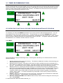
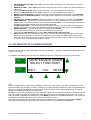
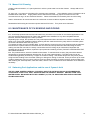
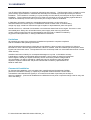
INSTALLATION AND OPERATING INSTRUCTIONS I INSTALLATION AND OPERATING INSTRUCTIONS E Series Salt Chlorinator ND ModelsBolero M20 CSD and M25 CSDCleaner Part numbers 10814 and 10815 INSTALLATION AND OPERATING INSTRUCTIONS Melbourne: 03 8796 8600 Sydney: 02 9853 2100 Brisbane: 07 3308 5400 27/05/2010 Gold Coast: 07 5552 2600 Townsville: 07 4750 3100 Adelaide: 08 8152 7600 Perth: 08 9350 2600 [email protected] www.astralpool.com.au INDEX 1.0 Introduction…………………………………………………………………………………………………. 3 2.0 Installation…………………………………………………………………………………………………... 3 2.1 Mounting the Controller……………………………………………………………………… 4 2.2 Connecting the PVC Acid Tube……………………………………………………………….. 4 …………………………………………………………………………………………………….. 5 3.0 Starting your Chlorinator……………………………………………………………………………………. 6 3.1 Set Up………………………………………………………………………….…………………………….. 6 3.2 Setting Timers………………………………………………………………………………………………... 6 3.3 Timer Recommendations…………………………………………………………………………………… 7 4.0 Operating Functions Accessed through Maintenance Program………………………………………… 7 5.0 Calibration of pH sensor/probe……………………………………………………………………………... 8 6.0 Operation………………………………………………………………………………………………………. 9 6.1 Adjusting Chlorine Output……………………………………………………………………………………. 9 6.2 Adjusting pH Set Point………………………………………………………………………………………. 10 7.0 General Operation/Pool Chemistry…………………………………………………………………………. 10 7.1 Setting the right Chlorine output and Operation times…………………………………………… 10 7.2 Stabiliser………………………………………………………………………………………………. 10 7.3 pH Level………………………………………………………………………………………………. 10 7.4 Total Alkalinity……………………………………………………………………………………….. 10 7.5 Salt Level…………………………………………………………………………………………….. 11 7.6 Acid Handling………………………………………………………………………………………… 11 7.7 Cell Cleaning…………………………………………………………………………………………. 11 8.0 Maintenance of pH sensing and dosing……………………………………………………………………. 12 9.0 Fault indication and troubleshooting………………………………………………………………………… 13 10.0 Warranty……………………………………………………………………………………………………… 14 E- Series Chlorinator M20 CSD & M25 CSD V05_10 2 Warning: The appliance is not intended for use by young children or infirm persons without supervision. Please ensure that young children are supervised to ensure that they do not play with the appliance. Controller must be installed according to AS 3000 wiring rules. If the supply cord is damaged it must be replaced by Astral Pool or its service agent or a similar qualified person in order to avoid a hazard. 1.0 INTRODUCTION Congratulations on your purchase of the E Series M20 or M25 CSD salt Chlorinator. The CSD models incorporate a unique patent pending self cleaning process using Hydrochloric Acid which is automatically dosed into the electrolytic cell at the end of the filter cycle. The self cleaning process occurs at the end of each filtration cycle and removes most debris and calcium from the electrodes that make up the cell. In addition, your CSD chlorinator has a pH sensor and will automatically maintain the pH of your pool water. The correct pH balance of your pool water significantly increases the effectiveness of the chlorine in the water and if not maintained at the correct level, can cause harm to the interior finish of your swimming pool or spa and reduce the disinfection time of the chlorine. The purpose of the M20 CSD and M25 CSD Chlorinators is to significantly reduce the level of daily and weekly maintenance required to keep you pool and spa sparkling clean and healthy to swim in. These installation and operating instructions will guide you through installation, operation and maintenance of your new chlorinator. Regular maintenance will ensure many years of trouble free operation. 2.0 INSTALLATION Controller Acid Pump located behind removable draw 2.1 Mounting the Controller: Choose a location that is preferably out of direct sunlight, near the filter system. The controller should be located 1 metre above ground level to prevent rain splash back or sprinkler system damage to the underside of the controller. The controller must be mounted on a vertical surface/wall. If mounted on a post, a flat sheet 20mm larger than the controller housing must be used. a. Mount the wall bracket using the screws provided on a secure wall. b. Glue 50 mm Sensor T piece into plumbing line after filter and Heater (if installed. c. Glue Chlorinator cell into line as per drawing below after filter, heater, solar (if installed) and after sensor T price. d. Remove draw on Controller for easy access to connection points and acid pump e. Plug the pH sensor into the underside of the controller in the location marked “pH” f. Plug filter pump 3 pin plug into underside of Controller E- Series Chlorinator M20 CSD & M25 CSD V05_10 3 g. Remove cap from pH sensor and screw firmly 50mm T installed in the plumbing. Do Not Overtighten. h. The water connections to the Cell are 50mm high pressure PVC pipe. Glue into Union tails using PVC glue as show above. Direction of flow through the cell is not critical. WARNING: Never install the cell before the pump or heater i. The cell must be installed with the barrel unions underneath and the cell should be horizontal. Both 40mm and 50mm fittings have been provided. Make sure that the o’rings are correctly fitted and the unions are done up tightly. j. Hang Controller on wall bracket and plug power supply lead into 3 pin 10 amp outlet. k. Ensure removable draw is replaced on controller to protect from water ingress. l. ACID SHOULD BE DILUTED MINIMUM 1:2 ALWAYS ADD ACID TO WATER (NOT WATER TO ACID) NEVER MIX CHEMICALS CHEMICALS MUST BE STORED IN ACCORDANCE WITH RELEVANT STANDARDS AND DANGEROUS GOODS CODES. CONSULT YOUR AUTHORISED BUILDER OR POOL SHOP TECHNICIAN FOR ADVICE. WHEN HANDLING ACID, SAFETY GLOVES AND GOGGLES SHOULD ALWAYS BE USED E- Series Chlorinator M20 CSD & M25 CSD V05_10 4 2.2 CONNECTING THE PVC ACID TUBE Before installing the unit in position on the wall or post, the length of the PVC tubing provided should be measured and taken into consideration. Ensure the Controller and Cell are close enough for the power supply lead to reach the cell and sufficient PVC tube exists to connect Acid Container and Cell. To avoid loss of water from the system, close all stop valves before cutting any lines. Thread the PVC tube through the hole in the cap or shoulder of the chemical container and fit the nonreturn or check valve and the weight. Ensure that the non-return valve is fitted correctly (arrow indicates the direction of flow) Drop the weight, with the non-return valve into the bottom of the container. Connect the other end of the PVC tube to the inlet of the acid pump on the underside of the Controller. Connect the remaining hose from the outlet of the acid pump on the underside of the controller. The remaining end of the PVC hose should be pushed through the cable gland in the end of the Cell Cap so that it protrude 5 mm on the inside. TIP: Soaking the ends of the PVC tubing in hot water or gentle heating with a lighter makes it easier to push onto the barb. When installing acid container in a filter enclosure, which has no ventilation, it is recommended that the hole in the cap of the container is cut or drilled to fit tightly around the tubing, so that fumes from the acid will not corrode the equipment. It will be necessary to drill a second hole in the cap fitted tightly with a length of tubing which should then be vented outside the filter enclosure. This procedure is recommended only where the filter enclosure has no ventilation and is to protect the equipment. E- Series Chlorinator M20 CSD & M25 CSD V05_10 5 3.0 STARTING YOUR CHLORINATOR Your Chlorinator Controller operation can be divided into 4 areas; a. MAINTENANCE – selects specialised functions of your chlorinator and initial set up of Chlorinator to suit your pool and spa. b. SET – selects changes in Chlorine Product and pH of your pool and spa water c. CLOCK & TIMER buttons – sets current time and filtration, chlorine production and pH monitoring and adjustment times from Monday to Friday and Weekends d. Pool and Spa Mode – Allows selection of pool mode where controller will produce chlorine suitable for pool and Spa Mode, where chlorine production and acid dosing is reduced to suit a smaller volume of water in the Spa. 3.1 SET UP a. Press “Pool Mode” button until Manually Off appears and then Press “Clock” Button b. Select “Day” and use buttons adjacent to LCD screen to set the current day, hour and minute. The clock is a 24 hour clock. Timer Clock DAY: WEDNESDAY TIME: 11:07 DAY HOUR Up & down buttons MIN Select Day and use up & down buttons to change day. Select hour and use up or down buttons to change hour. Select Min and use up or down buttons to change the minute 3.2 SETTING TIMERS Your E Series CSD Chlorinator has 2 timers enabling you to set two different periods in which your filtration pump, acid and chlorine production will operate. Different periods can be set for the weekend compared to weekdays. Timers are set by entering a start time, and a RUN time for how long you want to operate (i.e. Mon – Fri T1 Start 14:00 and Mon – Fri T1 Run 6:00 will run the chlorinator/pump during weekdays from 14:00 for 6.00 hours). To set timers, do the following: a. Press the TIMER button. b. Press HOUR button to set the hour for the timer selected and use the Up/Down arrows to change the time. c. Press MIN button to select the minutes for the timer selected and use the Up/Down arrows to change the time. Press the NEXT button to select the RUN time or another time and set as required. Note: The RUN time represents the number of hours you want the unit to operate for. d. When finished, press the NEXT button a number of times to scroll through the other times until you return to normal display. This saves your new settings. e. Select Auto Sanitising by pressing the POOL mode button. The POOL mode button has three settings, manually ON which turns on system indefinitely, manually OFF which turns system off indefinitely, and AUTO model which sets the controller on timer clock mode. In AUTO mode the LCD screen will display the date and pool sanitiser message. E- Series Chlorinator M20 CSD & M25 CSD V05_10 6 3.3 TIMER RECOMMENDATIONS: Hurlcon recommend that you use two timers, one for the morning and one for the evening and typically for periods of 2-5 hours for each. Your E Series CSD Chlorinator is most effective if running in the early morning or evening when it is cooler (strong sunlight consumes more chlorine). As a default, the control is set to come on at 08:00 hours and 16:00 hours both for periods of 4 hours. Timer Clock WEDNESDAY 11:07 POOL SANITISING OFF UNIT 16:00 SET MAINT 4.0 OPERATING FUNCTIONS ACCESSED THROUGH MAINTENANCE PROGRAM To backwash your filter press BWASH and then the up or down arrows to select the backwash time. You can press ABORT at any time to finish the back wash. To rinse the filter, you can select BWASH again and then select the time. Using this feature will ensure your sand filter is backwashed for the correct time. Note: Ensure pump is off when changing the position of the backwash valve on your filter. As a guide, sand filters should be backwashed for 2 to 3 minutes, and then rinsed for 1 minute. Press MAINT Timer Clock WEDNESDAY 11:07 POOL SANITISING OFF UNIT 16:00 SET DOSE NEXT Then press NEXT to display the following Screen. Selecting dose will allow you to override the time clock and allow the following: i. Sanitise until the first timer tomorrow morning. This allows for additional circulation of the swimming pool water after treatment or cleaning ii. Manually prime Acid Pump. This allows for the clear PVC tube to be filled with Acid on initial start up or after changing or refilling the Acid Container. The priming period is for 300 seconds but can be stopped at any time. Should the tube not be completely filled with Acid after 300 seconds repeat the process. iii. Manually Dose Acid. Selecting this function allows you to manually dose acid for a predetermined time. Should your pool professional recommend the addition of Acid to your pool, select this function and press the up (or down) arrow to select the quantity of acid in litres you wish to dose. Press ACCEPT. The controller will then ask you what mode you wish the unit to revert to at the completion of Acid dosing, “AUTO”, “ON” or “OFF”. In normal circumstances you will select “AUTO” which puts the unit back into time clock operation. iv. INSTALL allows the unit to be set up for your pool or spa. This should only be selected in the initial start up of your Chlorinator. Select INSTALL and the following will occur: a. SET POOL WATER VOLUME, select YES and then use up or down arrows to change the volume of your pool. Press ACCEPT E- Series Chlorinator M20 CSD & M25 CSD V05_10 7 b. SET SPA WATER VOLUME, select YES if your have a SPA attached to your pool and then set volume. Press ACCEPT c. ENABLE ALARM? Select YES and an alarm will sound if you run our of ACID or the ACID adjustment is not working. d. SELECT the Maximum pH value to trigger the alarm. It is recommended this is set at 8.0. e. SELECT the Minimum pH value to trigger the alarm. It is recommended this is set at 6.8. f. DOSE CYCLE 240 Seconds. In normal circumstances this will suffice for most pools – press ACCEPT. g. ADJUST CELL CLEAN FREQUENCY – Most pools require medium level of cell clean frequency, press ACCEPT. h. ADJUST CELL CLEAN DURATION – Most pools require a medium duration cell clean, press ACCEPT. i. TIMER ENABLED – this function will turn your timer on or off. If the chlorinator is not connected to an external timer clock or Genus Remote Control system Press ACCEPT. If an external timeclock is used to operate the chlorinator and filter pump then change to disabled. j. FLUSH AFTER TIMER. This function will turn the filtration pump on 15 minutes after the time period is finished to ensure the pH probe is not affected by ACID during the timer OFF period. Press ACCEPT k. RESET SYSTEM? If you are happy with your settings press ACCEPT. i. The unit will now reset itself with your individual settings to suit your pool. ii. Cycle through POOL MODE button to select Auto, Manually ON or Manually OFF. a. AUTO will allow the unit to operate your filter pump, chlorine production and pH adjustment on the timer periods you have selected. If you have not changed the timer periods, the default timer turns the filter pump and unit on at 08:00 hours for a period of 4 hours and then again at 16:00 hours for a further period of 4 hours. This is the default setting from the factory. 5.0 CALIBRATION OF PH SENSOR/PROBE: From time to time, the pH sensor will require cleaning and calibration. Typically, calibration should take place one every 6 to 12 months. To Calibrate, Press MAINT and next until CAL appears on the LCD. Select CAL to commence the process. Timer Clock MAINTENANCE MODE SELECT FUNCTION? EXIT CAL NEXT CAL The pH probes/sensor has been factory calibrated. However it is a good practice to check the adjustment for the probe periodically (say 6 months or earlier if required). The probe should be cleaned first (refer under Maintenance page 13 for cleaning) and allowed to settle down for about 4-5 minutes before adjusting/calibrating. Calibration solution is available via AstralPool as a spare part. pH When the controller is in Manual Off mode, remove the pH probe from the pipe line (shut off the filter pump and close any isolation valves to avoid water spill), clean the probe (see under Maintenance) and place it in a 7.5 pH Easy cal Solution (available from AstralPool). Press MAINT and then next until CAL is displayed. The unit will ask CHANGE PH CALIBRATION, select YES. Select NO to Filter Pump on? The display will indicate that the system is measuring pH. When the pH is displayed, press the UP or DOWN buttons to get the display to indicate the same value as the buffer (7.5) and then press ACCEPT E- Series Chlorinator M20 CSD & M25 CSD V05_10 8 6.0 OPERATION During operation, adjustments are made by the SET button. Timer Clock WEDNESDAY 16:05 POOL SANITISING ON UNIT 20:00 SET MAINT 6.1 ADJUSTING CHLORINE OUTPUT Press the SET button to change the chlorine output and the pH of your Pool CHANGE CHLORINE SET POINT Timer Clock YES NO Press YES to change the output Timer SET POINT 6 Clock ACCEPT Use the up and down buttons to change the Set Point between 0 and 8. 0 chlorine output should only be used when there is no salt in the water. In summer, the chlorine should be set between 6 and 8 and you should regularly check your chlorine level in your swimming pool to determine if the output should be increased or decreased. Rely on your pool professional for advice on the recommended chlorine level in your pool. As a guide the free chlorine level should be between 1.0 ppm and 3.0 ppm. E- Series Chlorinator M20 CSD & M25 CSD V05_10 9 6.2 ADJUSTING PH SET POINT Continue through the SET menu to change the pH balance of your pool. As a guide the pH in your pool should be set between 7.2 and 7.8. This will be determined by the type of pool you have, (Concrete, Fibreglass, Vinyl Liner) and you should rely on your pool builder or pool professional to recommend the correct pH Set Point. Use the up and down arrows to set your pH value. Once the pH value is set your LCD screen will return to the operating information screen which will cycle through the current status of the chlorinator, the chlorine output setting (between 0 and 8) and the pH set point. 7.0 GENERAL OPERATION/POOL CHEMISTRY 7.1 Setting the Right Chlorine Output and Filtration Time Your E Series CSD Chlorinator must be run every day to ensure that your pool is correctly sanitised. As the sun dissipates chlorine, running times are higher in the summer compared to the winter. Astral Pool recommend that you initially run you chlorinator at maximum output on level 8. Summer You should set your Chlorinator to operate for 8 to 10 hours per day. Ideally, run it for 4-5 hours in the morning (say 8-12pm) and 4-5 hours in the evening (say 6.00-11pm). In extremely hot weather it may be necessary to extend the running time if you find that the free chlorine level is too low. Winter You should set your Chlorinator to operate for 6 to 8 hours per day. Again, running it in the morning and evening is preferable. A lower chlorine output level may be selected. Checking Chlorine Level. Ideally, check your Chlorine level after the morning operating period. The free chlorine residual level should be somewhere between 1 and 3 parts per million. Increase or decrease the output of the Chlorinator to get the right residual chlorine level. It may also be necessary to adjust the operating period if you are running at minimum or maximum output. 7.2 Stabiliser Sunlight rapidly dissipates the amount of free chlorine in your pool. Chlorine stabiliser greatly reduces this effect. Without stabiliser, you may need to run your Chlorinator and filtration system up to 16 hours per day longer!!! Keep the Stabiliser reading between 30 and 60ppm. 7.3 pH Level You should keep you pH level between 7.0 and 7.4 for fibreglass pools and 7.2 to 7.8 for other pools. 7.4 Total Alkalinity The ideal range is between 80 and 120 ppm. E- Series Chlorinator M20 CSD & M25 CSD V05_10 10 7.5 Salt Level Salt level should be maintained around 4,000ppm but should never be allowed to fall below 3,000ppm. Although salt is not consumed by the Chlorinator, salt is lost during backwashing, and when your pool overflows due to rain or splashing. The correct salt level is important to cell life and the effective operation of your chlorinator. A typical pool of around 50,000 litres requires 200kg of salt to initially set-up the pool to 4,000ppm. A low salt level warning is indicated on your E Series CSD Chlorinator if the salt level drops. If Low Salt is indicated, check again in 24 hours and then if it is still indicated, add two 25kg bags of salt to the shallow end of your pool. Run the filtration system for approx. 6 hours to help mix the salt in the pool. It can take up to a day for the salt to fully dissolve. If the low salt light is still on, then you should get your pool water tested. If the Salinity is above 4000ppm then you may need to have your Chlorinator checked. Warning: Some people recommend that you put salt directly in the skimmer box. This is a very bad practice as it allows very high concentrations of salt to be passed through your filtration and other pool equipment. 7.6 ACID Handling Hydrochloric Acid should be handled with extreme care. Refer to Material Safety Data Sheets on Hydrochloric Acid. Do not inhale Acid fumes. Do not spill and handle with extreme care during transport. Use protective gloves and goggles. In the case of spillage wash down with fresh water immediately. Keep our of reach of children. 7.7 Cell Cleaning At the end of each filter on cycle, the chlorinator will automatically clean the electrodes in the Cell. This is a patent pending process and takes about 30 minutes. The cleaning phases consist of the following after the timer period is completed. This process will remove most calcium build up on the cell. Manual cleaning may be periodically required. 1. 2. 3. 4. 5. 6. Check for water flow Acid pumps doses acid into the cell Pre clean time allows acid to mix with the pool water cleaning the cell electrodes Cell energised to agitate water and acid. Second clean phase starts to allow reaction between the low pH and debris on the cell. Pool Pump is started for 2 minutes to flush cell. This process will greatly reduce manual cleaning frequency of your cell. In pools with very high calcium levels, the cleaning duration and frequency may require adjustment. It is usual to see a visible trace of Calcium on the electrodes in the cell after cleaning but the majority of Calcium and debris should be removed by this process. Should calcium and debris on the cell start to fill the gap between the electrodes, manually clean the cell in a mild acid solution or cell cleaning solution available from your pool professional Ensure Acid is always available to clean the cell electrodes. Failure to ensure available acid will increase manual cleaning frequency and may void warranty. E- Series Chlorinator M20 CSD & M25 CSD V05_10 11 7.8 Manual Cell Cleaning Create a mild acid solution, of 1 part hydrochloric acid to 5 parts water in a bucket of water. Always add Acid to the water. To clean cell – turn power to chlorinator off to prevent pump operating. Close isolation valves if chlorinator cell is installed below water level. Supply leads, sensor lead and PVC tube may require removal from the Cell. Unscrew the lock ring in an anti clockwise direction. Remove electrode from assembly from the cell housing. Soak in Acid solution for 30 minutes and use a soft brush to remove calcium deposits and debris. Reassemble Cell housing and reconnect power lead and PVC tube. Turn power onto chlorinator. 8.0 MAINTENANCE OF PH SENSING AND DOSING 8.1 Acid Pump squeeze tube must be lubricated every 6 months or more often in commercial applications. Use only the recommended lubricant RC Tube Lube available from AstralPool or any other compatible silicone lubricant, otherwise damage to the tube is possible. Depending upon usage, the squeeze tube may need replacement after 12months on a domestic installation, and earlier on a commercial installation. Before replacing the tube make sure that any stop valves in the filter system are closed. Otherwise water loss may occur. (To replace the tube, remove controller draw, remove retaining screws from the pump head and pull the tube free. Disconnect the squeeze tube from the barbs and reconnect the new squeeze tube after lubricating the same, making sure that the new tube is correctly connected to the PVC tubing as per instructions. Reposition the squeeze tube in the unit as before, replace the pump head and retaining screws.) DO NOT OVERTIGHTEN THE RETAINING SCREWS. 8.2 The probes/sensors, which are sensitive instruments. To maintain their accuracy they should be cleaned periodically by household detergent abrasive like Jiff. Jiff is the preferred option. The ORP probe tip can be contaminated (generally observed by a copper or brownish coating – this should always look shiny silver) which will give a false reading to the Controller causing no dosing/over dosing of chemical. As the pH sensor tip is made of glass, please take care, for even a hair line crack can cause the sensor to read incorrectly causing malfunction. After cleaning the sensors/probes, wash with water, allow 5-10min. to settle and check calibration or re-calibrate if necessary. 8.3 Swimming Pool Applications and the use of Cyanuric Acid USE OF A SUN SCREEN CHEMICAL (CYANURIC ACID) FOR OUTDOOR POOLS IS RECOMMENDED. CHECK WITH YOUR LOCAL POOL SHOP AND USE THE CORRECT DOSAGE. ENSURE YOUR POOL WATER IS WELL BALANCED WITH THE CORRECT pH, TDS, TA AND STABILSER LEVELS AND FREE FROM PHOSPHATES. E- Series Chlorinator M20 CSD & M25 CSD V05_10 12 9.0 Fault Indication and trouble shooting Fault Indication No Flow Low salt Display blank Low/No chlorine production Potential Cause Pump turned off/disconnected or valves closed Remedy Ensure valves/pump on Sense wire disconnected from cell Connect sense wire to cell Salt level in pool has dropped too low See section 7.5 above Pool water temperature is low Cell has calcified Increase salt level or raise water temperature See section 7.8 Cell has failed Call a technician No Power to Controller Plug in controller and ensure mains power available Fuse blown Cables not connected to cell Replace fuse (3 amp slow blow) Connect cables Timer period too short Increase timer period Chlorine output level too low Increase chlorine output Filter needs backwashing Backwash filter Pool stabiliser too low Get Stabiliser between 30 and 60 ppm Salt level too low Increase salt to above 4000ppm Water Temperature below 15 deg Increase water temperature or salt level Excessive Salt Level (Above 10,000 ppm) Chlorinator cuts out on overload, reduce salt level to 4000 ppm Call a technician Clock loses time when mains power removed Battery life expired Cell does not clean No Acid in Drum Replenish or replace Acid Drum Cell does not clean PVC blocked or leaking Clean or replace tube pH too high Probe/sensor malfunction Cell does not clean High calcium level in swimming pool Clean and Calibrate probe/sensor Call service technician to adjust cell cleaning duration and frequency Cell does not clean and pH too high The Acid Pump (Roller (H) Block) on the inside of the unit does not dispense chemicals E- Series Chlorinator M20 CSD & M25 CSD V05_10 No chemicals in the tank. Injection point blocked. Air leak at the connection where the tube from the drum connects onto the pump tube. Chemical container airtight. Roller or H block broken. Pump head cracked. Squeeze tube needs replacement. 13 10.0 WARRANTY Your E Series CSD Chlorinator is covered by a limited 5 year warranty. The Electrolytic Cell is covered by a full 5 years warranty against defects in materials and assembly from the date of purchase plus 30 days to allow for installation. The Controller is covered by a 2 year warranty from the date of purchase plus 30 days to allow for installation. The pH sensor/probe and PVC Acid Tube are covered by a 12 month warranty against defects in materials and assembly form the date of purchase plus 30 days to allow for installation. In field labour is limited to capital city metropolitan areas and within a 20 km radius of an authorised Astral Pool service agent. For installations outside of these areas, a small travelling charge may apply. Astral Pool reserves the right to replace or repair defective parts at its option. Should a fault occur, call Astral Pool Australia or an Authorised Astral Pool Service Agent. There are no user serviceable parts. Always turn off and disconnect power supply when removing Chlorinator control or disconnecting the Cell. No representations may be made on AstralPool’s behalf by any person unless permission, in writing is obtained from AstralPool. Limitations All warranties only apply if the equipment is installed and operated in complete compliance with the installation and operating instructions. Specific limitations and exclusions include but are not limited to, failure to keep Acid container full, failure to lubricate PVC Acid Tube with approved lubricate, Failure to maintain, clean and calibrate pH sensor/probe, water ingress into Chlorinator control. The squeeze tube in the Acid Pump Head is a consumable item and not covered under warranty. AstralPool assumes no liability for consequential damages of any kind. In field labour warranty is applicable in capital city metropolitan areas and within a 20 km radius of Astral Pool Authorised Service Agents. Should you request a warranty service call and the problem is diagnosed as non-warrantable, you will be charged for a diagnostic service call plus any parts and labour required to repair the Chlorinator. No person is authorised to make any representations on behalf of Astral Pool. Commercial Installation On Commercial Installations, such as health clubs, motels/hotels and hydrotherapy facilities, parts and in field labour warranty (in capital city metropolitan areas and within a 20 km radius of AstralPool Authorised Service Agents) is 12 months from the date of purchase plus 30 days to allow for installation. (Commercial Installations are defined as those pools or spas that charge a fee for entry and use of the facility). E- Series Chlorinator M20 CSD & M25 CSD V05_10 14 E- Series Chlorinator M20 CSD & M25 CSD V05_10 15 INSTALLATION AND OPERATING INSTRUCTIONS I INSTALLATION AND OPERATING INSTRUCTIONS ASTRALPOOL Pty. Limited. A.B.N. 97 007 284 504 www.astralpool.com.au email: [email protected] Information and specifications subject to change without notice. Victoria: Ph: (03) 8796 8600 Fax: (03) 8796 8670 New South Wales: Ph: (02) 9853 2100 Fax: (02) 98532170 Queensland: Ph: (07) 3308 5400 Fax: (07) 3308 5470 South Australia: Ph: (08) 8152 7600 Fax: (08) 81527670 E- Series Chlorinator M20 CSD & M25 CSD V05_10 Western Australia: Ph: (08) 9350 2600 Fax: (08) 9350 2670 Gold Coast: Ph: (07) 5552 2600 Fax: (07) 5552 2670 Townsville: Ph: (07) 4750 3100 Fax: (07) 4750 3170 16