1
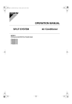
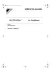
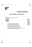
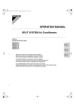
00_CV_3PA60995-8V.fm Page 1 Monday, July 10, 2006 12:02 PM OPERATION MANUAL SPLIT SYSTEM Air Conditioners MODELS Ceiling mounted cassette type (Multi flow model) FCQ100PV4A FCQ125PV4A FCQ140PV4A Thank you for purchasing this Daikin air conditioner. Carefully read this operation manual before using the air conditioner. It will tell you how to use the unit properly and help you if any trouble occurs. This manual explains about the indoor unit only. Use it along with the operation manual for the outdoor unit. After reading the manual, file it away for future reference. 00_CV_3PA60995-8V.fm Page 3 Monday, July 10, 2006 12:02 PM 2 4 11 1 3 6 hr C hr 5 7 NOT AVAILABLE TEST 8 10 9 12 L H 13 20 19 TEST 15 18 14 17 16 21 1 j k i a h f g e d e 3 b c d e f hr C l 2 3 4 H 01_EN_3PA60995-8V.fm Page 4 Monday, July 10, 2006 9:22 PM CONTENTS ILLUSTRATIONS.................................................................3 WHAT TO DO BEFORE OPERATION................................4 SAFETY CONSIDERATIONS .............................................4 OPERATION RANGE..........................................................5 INSTALLATION SITE ..........................................................6 NAME AND FUNCTION OF EACH SWITCH AND DISPLAY ON THE REMOTE CONTROLLER .....................6 OPERATION PROCEDURE................................................7 OPTIMUM OPERATION......................................................8 MAINTENANCE (FOR SERVICE PERSONNEL)................9 NOT MALFUNCTION OF THE AIR CONDITIONER.........10 TROUBLE SHOOTING......................................................11 WHAT TO DO BEFORE OPERATION This operation manual is for the following system with standard control. Before initiating operation, contact your dealer for the operation that corresponds to your system. Outdoor unit Unit with remote controller NOTE • If the unit you purchased is controlled by a wireless remote controller, also refer to the wireless remote controller’s operation manual. If your installation has a customized control system, ask your dealer for the operation that corresponds to your system. TWO REMOTE CONTROLLERS CONTROL SYSTEM Confirm the following if your unit is the following control system type. • Two remote controllers control system Two remote controllers control one indoor unit. The unit is individually operated. NOTE • Contact your dealer in case of two remote controllers control system. Names and functions of parts Refer to figure 2 on page 3 a b c d e f g h i j k l 4 Indoor unit Outdoor unit Remote controller Inlet air Discharge air Air outlet Air flow flap (at air outlet) Refrigerant pipe, connection electric wire Drain pipe Air inlet The built-in air filter removes dust and dirt. Drain pumping out device (built-in) Condensate removed from the room during cooling. Ground wire Wire to ground from the outdoor unit to prevent electrical shocks. SAFETY CONSIDERATIONS We recommend that you read this instruction manual carefully before use to gain full advantage of the function of the air conditioner, and to avoid malfunction due to mishandling. This air conditioner comes under the term “appliances not accessible to the general public”. • The precautions described below are WARNING and CAUTION. These are very important precautions concerning safety. Be sure to observe all of them without fail. WARNING ....... These are the matters with possibilities leading to serious consequences such as death or serious injury due to erroneous handling. CAUTION ........ These are the matters with possibilities leading to injury or material damage due to erroneous handling including probabilities leading to serious consequences in some cases. • After reading, keep this manual at a place where any user can read at any time. Furthermore, make certain that this operation manual is handed to a new user when he takes over the operation. WARNING Avoid exposure of your body directly to the cold air for a long time, or avoid excessive exposure of your body to the cold air. Otherwise, your physical condition may be deteriorated and/or your health may be ruined. When the air conditioner is in abnormal conditions (smell of something burning, etc), turn off power, and contact the dealer where you purchased the air conditioner. Continued operation under such circumstances may result in a failure, electric shock, and fire. Ask your dealer for installation of the air conditioner. Incomplete installation performed by yourself may result in a water leakage, electric shock, and fire. Ask your dealer for improvement, repair, and maintenance. Incomplete improvement, repair, and maintenance may result in a water leakage, electric shock, and fire. Do not insert your finger, a stick, etc., into the air inlet, outlet, and fan blades. A fan in high-speed running may result in injury. For refrigerant leakage, consult your dealer. When the air conditioner is to be installed in a small room, it is necessary to take proper measures so that the amount of any leaked refrigerant does not exceed the limiting concentration even when it leaks. If the refrigerant leaks exceeding the level of limiting concentration, an oxygen deficiency accident may happen. For installation of separately sold component parts, ask a specialist. Be sure to use the separately sold component parts designated by our company. Incomplete installation performed by yourself may result in a water leakage, electric shock, and fire. Ask your dealer to move and reinstall the air conditioner. Incomplete installation may result in a water leakage, electric shock, and fire. 01_EN_3PA60995-8V.fm Page 5 Monday, July 10, 2006 9:22 PM The refrigerant in the air conditioner is safe and normally does not leak. If the refrigerant leaks inside the room, the contact with a fire of a burner, a heater or a cooker may result in a harmful gas. Do not use the air conditioner until when a service person confirms to finish repairing the portion where the refrigerant leaks. Do not use any fuse with improper capacity. The use of a piece of wire and whatnot may result in a failure and fire. Be sure to establish an earth. Do not earth the unit to a utility pipe, arrester, or telephone earth. Incomplete earth may cause electrical shock, or fire. A high surge current from lightning or other sources may cause damage to the air conditioner. Be sure to install an earth leakage breaker. Failure to install an earth leakage breaker may result in electric shocks, or fire. CAUTION Do not use the air conditioner for other purposes. Do not use the air conditioner for a special application such as the storage of foods, animals and plants, precision machines, and art objects as otherwise the deterioration of quality may result. Do not remove the air outlet of the outdoor unit. The fan may get exposed and result in injury. When the air conditioner is used in combination with burners or heaters, perform sufficient ventilation. Insufficient ventilation may result in an oxygen deficiency accident. Check and make sure that foundation blocks are not damaged after a long use. If they are left in a damaged condition, the unit may fall and result in injury. Neither place a flammable spray bottle near the air conditioner nor perform spraying. Doing so may result in a fire. To clean the air conditioner, stop operation, and unplug the power cord from the outlet. Otherwise, an electric shock and injury may result. Do not operate the air conditioner with a wet hand. An electric shock may result. Do not place items which might be damaged by moisture under the indoor unit which may be damaged by water. Condensation may form if the humidity is above 80%, if the drain outlet gets blocked or the filter is polluted. Do not place a burner or heater at a place directly exposed to the wind from the air conditioner. Incomplete combustion of the burner or heater may result. Do not allow a child to mount on the outdoor unit or avoid placing any object on it. Falling or tumbling may result in injury. Do not expose animals and plants directly to the wind. Adverse influence to animals and plants may result. Do not wash the air conditioner with water. Electric shock or fire may result. Do not install the air conditioner at any place where flammable gas may leak out. If the gas leaks out and stays around the air conditioner, a fire may break out. Execute complete drain piping for perfect drainage. Incomplete piping may result in a water leakage. The appliance is not intended for use by young children or infirm persons without supervision. Young children should be supervised to ensure that they do not play with the appliance. Consult with installation contractor for cleaning the inside of the air conditioner. Wrong cleaning may make the plastics parts broken or cause failure of water leakage or electric shock. Do not touch the air inlet or aluminium fin of the air conditioner. Otherwise, injury may be caused. Do not place objects in direct proximity of the outdoor unit and do not let leaves and other debris accumulate around the unit. Leaves are a hotbed for small animals which can enter the unit. Once in the unit, such animals can cause malfunctions, smoke or fire when making contact with electrical parts. OPERATION RANGE If the temperature or the humidity is beyond the following conditions, safety devices may work and the air conditioner may not operate, or sometimes, water may drop from the indoor unit. Cooling INDOOR TEMPERATURE DB WB HUMIDITY 80% or below 21 to 32 °C (Long time operation in a humidity over 80% may 14 to 25 °C cause condensation on the unit and dripping.) OUTDOOR TEMPERATURE DB –5 to 46 °C Heating INDOOR TEMPERATURE DB OUTDOOR TEMPERATURE DB –20 to 21 °C** WB –20 to 15.5 °C** 15 to 27 °C **–20~–15°CWB: Range for operation –15~15.5°CWB: Range for continuous operation DB: Dry bulb temperature WB: Wet bulb temperature The setting temperature range of the remote controller is 16°C to 32°C. Tips for saving energy • Be careful not to cool (heat) the room too much. Keeping the temperature setting at a moderate level helps save energy. • Cover windows with a blind or a curtain. Blocking sunlight and air from outdoors increases the cooling (heating) effect. Recommended temperature setting For cooling 26 to 28 °C For heating 20 to 24 °C 5 01_EN_3PA60995-8V.fm Page 6 Monday, July 10, 2006 9:22 PM INSTALLATION SITE DISPLAY “ CONTROL) Regarding places for installation • Is the air conditioner installed at a well-ventilated place where there are no obstacles around? • Do not use the air conditioner in the following places. a. Filled with much mineral oil such as cutting oil b. Where there is much salt such as a beach area c. Where sulfured gas exists such as a hot-spring resort d. Where there are considerable voltage fluctuations such as a factory or plant e. Vehicles and vessels f. Where there is much spray of oil and vapor such as a cookery, etc. g. Where there are machines generating electromagnetic waves h. Filled with acid and/or alkaline steam or vapor 3 ” (UNDER CENTRALIZED When this display shows, the system in UNDER CENTRALIZED CONTROL. (This is not a standard specification) DISPLAY “ ”“ TION MODE) 4 5 ”“ ”“ ”“ ” (OPERA- This display shows the current OPERATION MODE. Only for cooling models on which “ ” is not displayed. DISPLAY “ TION) TEST ” (INSPECTION/TEST OPERA- When the INSPECTION/TEST OPERATION BUTTON is pressed, the display shows the system mode is in. hr • Is a snow protection measure taken? For details, consult your dealer. DISPLAY “ 6 Regarding wiring • All wiring must be performed by an authorized electrician. To do wiring, ask your dealer. Never do it by yourself. • Make sure that a separate power supply circuit is provided for this air conditioner and that all electrical work is carried out by qualified personnel according to local laws and regulations. Pay attention to running noises, too • Are the following places selected? a. A place that can sufficiently withstand the weight of the air conditioner with less running noises and vibrations. b. A place where the hot wind discharged from the air outlet of the outdoor unit and the running noises. • Are you sure that there are no obstacles near the air outlet of the outdoor unit? Such obstacles may result in declined performance and increased running noises. • If abnormal noises occur in use, consult your dealer. Regarding drainage of drain pipe • Is the drain pipe executed to perform complete drainage? If proper drainage is not carried out from the outdoor drain pipes during air-conditioning operation, chances are that dust and dirt are clogged in the pipe. This may result in a water leakage from the indoor unit. Under such circumstances, stop the operation of the air conditioner, and then consult your dealer or our service station. 7 Refer to figure 1 on page 3 The illustrations in this operating manual correspond to the remote control format BRC1C type. 8 9 2 10 6 C ” (SET TEMPERATURE) DISPLAY “ L H ” (FAN SPEED) DISPLAY “ ” (AIR FLOW FLAP) DISPLAY “ ” (TIME TO CLEAN AIR FILTER) Refer to page 9. DISPLAY “ 11 ” (DEFROST/HOT START) Refer to page 7. “ ” is not displayed when the unit is in cooling only mode. NON-FUNCTIONING DISPLAY 12 13 14 If that particular function is not available, pressing the button may display the words “NOT AVAILABLE” for a few seconds. TIMER MODE START/STOP button Refer to page 8. TIMER ON/OFF button Refer to page 8. INSPECTION/TEST OPERATION button This button is used only by qualified service persons for maintenance purposes. Do not use it in normal operation. PROGRAMMING TIME button 16 Use this button for programming “START and/or STOP” time. TEMPERATURE SETTING button 18 OPERATION lamp (RED) The lamp lights up during operation. DISPLAY “ Refer to page 8. ON/OFF button Press the button and the system will start. Press the button again and the system will stop. This display shows PROGRAMMED TIME of the system start or stop. The display shows the fan speed: “LOW” or “HIGH”. 17 1 ” (PROGRAMMED TIME) This display shows the set temperature. 15 NAME AND FUNCTION OF EACH SWITCH AND DISPLAY ON THE REMOTE CONTROLLER hr Use this button for SETTING TEMPERATURE of the thermostat. FILTER SIGN RESET button Refer to page 9. FAN SPEED CONTROL button 19 Press this button to select the fan speed, LOW or HIGH, of your choice. 01_EN_3PA60995-8V.fm Page 7 Monday, July 10, 2006 9:22 PM 20 21 OPERATION MODE SELECTOR button Press this button to select OPERATION MODE. AIR FLOW DIRECTION ADJUST button Refer to page 8. NOTE • For the sake of explanation, all indications are shown on the display in figure 1 on page 3 contrary to actual running situations. OPERATION PROCEDURE Refer to figure 1 on page 3 • To protect the unit, turn on the main power supply switch 6 hours before operation. • If the main power supply switch is turned off during operation, operation will restart automatically after the power turns back on again. COOLING · HEATING · AUTOMATIC · FAN AND PROGRAM DRY Operation Operate in the following order. 1. Press OPERATION MODE SELECTOR button several times and select the OPERATION MODE of your choice as follows. COOLING Operation ................................ “ ” HEATING Operation ................................. “ ” AUTOMATIC Operation ............................ “ ” • In this operation mode, COOL/HEAT changeover is automatically conducted. FAN Operation ...........................................“ ” DRY Operation ..........................................“ ” • The function of this program is to decrease the humidity in your room with the minimum temperature decrease. • Micro computer automatically determines TEMPERATURE and FAN SPEED. • This system does not go into operation if the room temperature is below 16°C. Refer to figure 3 on page 3 2. Press ON/OFF button. OPERATION lamp lights up and the system starts OPERATION. ADJUSTMENT 3. Press TEMPERATURE SETTING button and program the setting temperature. Each time this button is pressed, setting temperature rises 1°C. Each time this button is pressed, setting temperature lowers 1°C. 5. Press AIR FLOW DIRECTION ADJUST button. Refer to page 8 for details. STOPPING THE SYSTEM 6. Press ON/OFF button once again. • OPERATION lamp goes off, and the system stops OPERATION. • The fan may keep on running for about 1 minute after the heating operation stops. (To start the next operation smoothly.) ATTENTION: • Do not turn OFF power immediately after the unit stops. Then, wait no less than 5 minutes. Water is leaking or there is something else wrong with the unit. • When the operation is started again immediately after being stopped, when the operation mode is changed over, or when the TEMPERATURE SETTING button is pressed then returned soon, the air conditioner will start the operation automatically about 5 minutes later (because the air conditioner is controlled so that excessive load is not applied). Characteristics of the heating operation (1) DEFROST OPERATION • As the frost on the coil of an outdoor unit increase, heating effect decreases and the system goes into DEFROST OPERATION. • The indoor unit fan stops and the remote controller displays shows “ ” (DEFROST/HOT START). • After 6 to 8 minutes (maximum 10 minutes) of DEFROST OPERATION, the system returns to HEATING OPERATION. (2) HOT START • In order to prevent cold air from blowing out of an indoor unit at the start of heating operation, the indoor fan is automatically stopped. The display of the remote controller shows “ ” (DEFROST/HOT START). (3) OPERATION START • For ordinary heating, it will take longer for the room temperature to reach the set temperature than with cooling. We therefore recommend starting the unit ahead of time using the timer operation. ADJUSTING THE AIR FLOW DIRECTION • Press the AIR FLOW DIRECTION button to adjust the air flow angle. NOTE • Set the temperature within the operation range shown in the table on page 5. • The temperature cannot be set in the fan operation. 4. Press FAN SPEED CONTROL button. High or Low fan speed can be selected. Up and down adjustment NOTE • In the heating operation, the fan stops during defrosting or at startup. It does not indicate any abnormality. 7 01_EN_3PA60995-8V.fm Page 8 Monday, July 10, 2006 9:22 PM 1. Press the AIR FLOW DIRECTION ADJUST button to select the air direction as shown below. swing The AIR FLOW FLAP display swings as shown left and the air flow direction continuously varies. (Automatic swing setting) Press AIR FLOW DIRECTION ADJUST button to select the air direction of your choice. The AIR FLOW FLAP display stops swinging and the air flow direction is fixed. (Fixed air flow direction setting) MOVEMENT OF THE AIR FLOW FLAP For the following conditions, micro computer controls the air flow direction so it may be different from the display. Cooling Heating Operation conditions • When room temperature is lower than the set temperature • When operating continuously at horizontal air flow direction • When room temperature is higher than the set temperature • At defrost operation Operation mode include automatic operation. The air flow direction can be adjusted in either of the following ways. • Automatic The air flow flap adjusts its position itself. • Fixed air flow direction The air flow direction can be fixed by the user. <Fixed air flow direction> ATTENTION: • The movable limit of the flap is changeable. Contact your Daikin dealer for details. • Avoid operating in the horizontal direction “ ” which may cause dew or dust to settle on ceiling. PROGRAM TIMER Operation Operate in the following order. • The timer is operated by the following two ways. Programming the stop time ( )............................... The system stops operating after the time setting has elapsed. Programming the start time ( )................................ The system starts operating after the time setting has elapsed. • The timer can be programmed for a maximum of 72 hours. • The start and the stop time can simultaneously be programmed. Refer to figure 4 on page 3 1. Press the TIMER MODE START/STOP button several times and select the mode on the display. The display flashes. For setting the timer stop ......... “ ” For setting the timer start ......... “ ” 8 3. Press the TIMER ON/OFF button. The timer setting procedure ends. The display “ or ” changes from flashing light to a constant light. NOTE • When setting the timer Off and On at the same time, repeat the above procedure (from 1 to 3) once again. • After the timer is programmed, the display shows the remaining time. • Press the TIMER ON/OFF button once again to cancel programming. The display vanishes. For example: Operation mode <Automatic> 2. Press the PROGRAMMING TIME button and set the time for stopping or starting the system. When this button is pressed, the time advances by 1 hour. When this button is pressed, the time goes backward by 1 hour. When the timer is programmed to stop the system after 3 hours and start the system after 4 hours, the system will stop after 3 hours and then 1 hour later the system will start. OPTIMUM OPERATION Observe the following precautions to ensure the system operates. • Adjust the room temperature properly for a comfortable environment. Avoid excessive heating or cooling. • Prevent direct sunlight from entering a room during cooling operation by using curtains or blinds. • Ventilate the room regularly. Using the unit for long periods of time requires attentive ventilation of the room. • Keep doors and windows closed. If the doors and windows remain open, room air will flow out and cause to decrease the effect of cooling and heating. • Do not place other heaters directly below the indoor unit. They may deform due to the heat. • Never place objects near the air inlet and the air outlet of the unit. It may cause deterioration in the effect or stop in the operation. • Turn off the main power supply switch when it is not used for long periods of time. When the main power supply switch is turned on, some watts of electricity is being used even if the system is not operating. Turn off the main power supply switch for saving energy. When reoperating, turn on the main power supply switch 6hours before operation for smooth running (Refer to MAINTENANCE). • When the display shows “ ” (TIME TO CLEAN AIR FILTER), ask a qualified service person to clean the filter (Refer to MAINTENANCE). 01_EN_3PA60995-8V.fm Page 9 Monday, July 10, 2006 9:22 PM MAINTENANCE (FOR SERVICE PERSONNEL) 3. Clean the air filter. Use vacuum cleaner A) or wash the air filter with water B). A) Using a vacuum cleaner WARNING • Only a qualified person is allowed to perform maintenance without daily maintenance. • Before touching any of connection wirings, be sure to turn off all power supply switches. • For installation of optional parts, only a qualified person is allowed to do so. Be sure to use optional parts specified by our company. Installation in your own manner may result in water leakage, electric shock or fire. B) Washing with water When the air filter is very dirty, use soft brush and neutral detergent Remove water and dry in the shade. CAUTION • Be sure to stop operation and turn the power switch off before cleaning the air conditioner. Otherwise, an electric shock or injury may result. • Do not wash the air conditioner with water. Doing so may result in an electric shock. • Consult with installation contractor for cleaning the inside of the air conditioner. Wrong cleaning may make the plastics parts broken or cause failure of water leakage or electric shock. • Use a stable stool. Use extra cautions when cleaning the air conditioner. NOTE • Do not wash the air conditioner with hot water of more than 50°C, as doing so may result in discoloration and/or deformation. • Keep away from fire, as doing so may result in burning. 4. Fix the air filter. (1) Hook the air filter to a protrusion on the suction grille. (2) Push the lower part of the air filter onto the protrusion at the lower part of the suction grille, and fix the air filter there. HOW TO CLEAN THE AIR FILTER Clean the air filter when the display shows “ ” (TIME TO CLEAN AIR FILTER). It will display that it will operate for a set amount of time. Increase the frequency of cleaning if the unit is installed in a room where the air is extremely contaminated. If the dirt becomes impossible to clean, change the air filter. (Air filter for exchange is optional) 1. Open the suction grille. Pull it downward slowly while pressing the buttons provided on two spots. (Do the same procedure for closing.) 5. Shut the suction grille. Refer to item No. 1. 6. After turning on the power, press FILTER SIGN RESET button. The “TIME TO CLEAN AIR FILTER” display vanishes. HOW TO CLEAN AIR OUTLET AND OUTSIDE PANELS 2. Remove the air filters. Pull the hook of the air filter out diagonally downward, and remove the filter. • Clean with soft cloth • When it is difficult to remove stains, use water or neutral detergent. • When the flap is extremely contaminated, remove it as below and clean or exchange it. (Flap for exchange is optional) NOTE • Do not use gasoline, benzene, thinner, polishing powder, liquid insecticide. It may cause discoloring or warping. • Do not let the indoor unit get wet. It may cause an electric shock or a fire. • Do not scrub firmly when washing the blade with water. The surface sealing may peel off. • Do not use water or air of 50°C or higher for cleaning air filters and outside panels. 9 01_EN_3PA60995-8V.fm Page 10 Monday, July 10, 2006 9:22 PM HOW TO CLEAN THE SUCTION GRILLE 1. Open the suction grille. Push it downward slowly while pressing the buttons provided on two spots. (Follow the same procedure for closing.) 6. Reattach the suction grille. Refer to item No. 2. 7. Close the suction grille. Refer to item No. 1. NOT MALFUNCTION OF THE AIR CONDITIONER The following symptoms do not indicate air conditioner malfunction. 2. Detach the suction grille. Open the suction grille 45 degrees and lift it upward. 3. Detach the air filter. Refer to “HOW TO CLEAN THE AIR FILTER”. 4. Clean the suction grille. Wash with a soft bristle brush and neutral detergent or water, and dry thoroughly. • When very grimy Directly apply the type of detergent used for cleaning ventilation fans or ovens, wait 10 minutes, and then rinse with water. 5. Reattach the air filter. Refer to “HOW TO CLEAN THE AIR FILTER”. 10 I. THE SYSTEM DOES NOT OPERATE • The system does not restart immediately after the ON/ OFF button is pressed. If the OPERATION lamp lights, the system is in normal condition. It does not restart immediately because a safety device operates to prevent overload of the system. After 3 minutes, the system will turn on again automatically. • The system does not restart immediately when TEMPERATURE SETTING button is returned to the former position after pushing the button. If the OPERATION lamp lights, the system is in normal condition. It does not restart immediately because a safety device operates to prevent overload of the system. After 3 minutes, the system will turn on again automatically. • The system does not start when the display shows “ ” (UNDER CENTRALIZED CONTROL) and it flashes for a few seconds after pressing an operation button. This is because the system is under centralized control. Flashes on the display indicates that the system cannot be controlled by the remote controller. • The system does not start immediately after the power supply is turned on. Wait at least 5 minute until the micro computer is prepared for operation. II. WHITE MIST COMES OUT OF A UNIT • When humidity is high during cooling operation. (In oily or dusty places) If the inside of an indoor unit is extremely contaminated, the temperature distribution inside a room becomes uneven. It is necessary to clean the inside of the indoor unit. Ask your dealer for details on cleaning the unit. This operation requires a qualified service person. • When the system is changed over to HEATING OPERATION after DEFROST OPERATION. Moisture generated by DEFROST becomes steam and exists. III. NOISE OF AIR CONDITIONERS • A ringing sound after the unit is started. This sound is generated by the temperature regulator working. It will quiet down after about a minute. • A continuous flow “Shuh” sound is heard when the systems is in COOLING or DEFROST OPERATION. This is the sound of refrigerant gas flowing through both indoor and outdoor units. • A “Shuh” sound which is heard at the start or immediately after the stop of operation or which is heard at the start or immediately after the stop of DEFROST OPERATION. This is the noise of refrigerant caused by flow stop and flow change. • A continuous low “Shah” sound is heard when the system is in COOLING OPERATION or at a stop. The noise is heard when the drain pump is in operation. 01_EN_3PA60995-8V.fm Page 11 Monday, July 10, 2006 9:22 PM • A “Pishi-pishi” squeaking sound is heard when the system is in operation or after the stop of operation. Expansion and contraction of plastic parts caused by temperature change makes this noise. IV. DUST FROM THE UNITS • Dust may blow out from the unit after starting operation from long resting time. Dust absorbed by the unit blows out. V. THE UNITS GIVE OFF ODORS The unit absorbs the smell of rooms, furniture, cigarettes, etc., and then emits them. VI.THE LIQUID CRYSTAL OF THE REMOTE CONTROLLER SHOW “ ” • It happens immediately after the main power supply switch is turned on. This shows that the remote controller is in normal condition. This continues temporary. II. If the system does not properly operate except for the above mentioned case, and none of the above mentioned malfunctions is evident, investigate the system according to the following procedures. 1. If the system does not operate at all. • Check if there is a power failure. Wait until power is restored. If power failure occurs during operation, the system automatically restarts immediately after the power supply recovers. • Check if a fuse has blown. Turn off the power supply. • Is the breaker blown? Turn the power on with the breaker switch in the off position. Do not turn the power on with the breaker switch in the trip position. (Contact your dealer.) ON Switch TROUBLE SHOOTING Trip position I. If one of the following malfunctions occurs, take the measures shown below and contact your dealer. The system must be repaired by a qualified service person. WARNING • When the air conditioner is in abnormal conditions (smell of something burning, etc), unplug the power cord from the outlet, and contact your dealer Continued operation under such circumstances may result in a failure, electric shock, and fire. • If a safety device such as a fuse, a breaker or an earth leakage breaker frequently actuates; Measure: Do not turn on the main power supply switch. • If the ON/OFF button does not properly work; Measure: Turn off the main power supply switch. • If water leaks from unit. Measure: Stop the operation. • If the display “ ” (INSPECTION), “UNIT No.”, and the OPERATION lamp flash and the “MALFUNCTION CODE” appears. OPERATION lamp UNIT No. C H INDOOR UNIT No. in which a malfunction occurs INSPECTION display MALFUNCTION CODE Breaker OFF 2. If the system stops operating after operating the system. • Check if the air inlet or outlet of outdoor or indoor unit is blocked by obstacles. Remove the obstacle and make it well-ventilated. • Check if the air filter is clogged. Ask a qualified service person to clean the air filters (Refer to MAINTENANCE). 3. The system operates but it does not sufficiently cool or heat. • If the air inlet or outlet of the indoor or the outdoor unit is blocked with obstacles. Remove the obstacle and make it well-ventilated. • If the air filter is clogged. Ask a qualified service person to clean the air filters (Refer to MAINTENANCE). • If the set temperature is not proper (Refer to ADJUSTMENT). • If the FAN SPEED button is set to LOW SPEED (Refer to ADJUSTMENT). • If the air flow angle is not proper (Refer to ADJUSTING THE AIR FLOW DIRECTION). • If the doors or the windows are open. Shut doors or windows to prevent wind from coming in. • If direct sunlight enters the room (when cooling). Use curtains or blinds. • When there are too many inhabitants in the room (when cooling). Cooling effect decreases if heat gain of the room is too large. • If the heat source of the room is excessive (when cooling). Cooling effect decreases if heat gain of the room is too large. Measure: Notify your dealer and inform him/her of the display. 11 00_CV_3PA60995-8V.fm Page 4 Monday, July 10, 2006 12:02 PM 3PA60995-8V EM06A029 (0607) HT