1
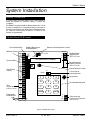
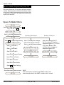
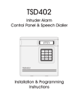
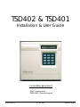
TSD402 & TSD401
Installation & User Guide
Compatible Equipment
9040 - Loudspeaker
TS400 REM - Remote Keypad
496523 Issue A
1 of 10
TSD402 & TSD401
TSD402 & TSD401
Overview
Introduction
Control Panel Operation
The TSD402 is a 5 zone (+ Final Exit) control panel with an
integral Speech Dialler. It is ideally suited for domestic
and small commercial installations, which require
additional security through the communication of audio
alarm messages over the telephone line.
Operation and programming is carried out from the
tactile rubber keypad on the control panel in
conjunction with the 16 character LCD display.
Features
Panel Input Voltage:
There are two programming menus within the system.
The engineer’s programming menu allows full system
The TSD401 was the predecessor to the TSD402. The programming (zone types, view log, walk test, exit time,
minor differences are listed below:
entry time, bell duration time, engineer’s code, reset
number, system options). The user programming menu
l The TSD401 could not use remote keypads
allows setting and unsetting of the system as well as
l The TSD401 had 32 seconds of record time for allowing the user to test the system. All speech dialler
speech messages.
programming, configuration and testing is also carried
l The TSD401 option 0 in engineer’s programming out within the “User Options” menu.
did not give option for part set & full set reporting ( it
was global).
Specifications
240V +/- 10% 50Hz
Current Consumption: 80 mA
l
l
l
l
l
l
l
l
l
l
l
l
5 Programmable zones Night, Access, Fire, PA & Power Supply
750mA
Keyswitch (plus common tamper)
Auxiliary power:
13.8v @ 300 mA
Final Exit zone
Remote Keypad:
TS400REM (normal 20mA,
Detector Reset output for Vibration and Smoke
alarm 32mA)
detectors
Trigger inputs
+ve or -ve applied, input
Internal and external volume controls
(speech dialler):
voltages 5 - 28V
16 character Liquid Crystal Display (LCD)
REN Value:
0
2 user passcodes and engineer’s passcode
BT Approval number: S/1100/3/R/503255
64 event log
Control Panel Dims:
205 (W) x 205 (H) x 64 (D) mm
Programmable Chime facility on all zones
Remote Keypad Dims: 130 (W) x 130 (H) x 30 (D) mm
Remote Reset facility
Control Panel Weight: 1.4 Kg
3 button Quick-Set for Home and Away
Battery Size
2.1Ah
Program data stored in NVM (recorded messages
Case
Construction:
3mm Polycarbonate
are not)
Environment:
0
- 55°C
Remote Keypad option (up to 4 x TS400 Remote
Keypads)
l
Auxiliary trigger inputs for the speech dialler
l
Speech dialler activations may report to different
telephone numbers
l
Built in microphone and speaker for record and
play-back
l
Messages may be up to a total of 60 seconds in
length
TSD402 & TSD401
2 of 10
496523 Issue A
TSD402 & TSD401
System Installation
Battery Connection
A 2.1Ah battery must be fitted to the control panel to
allow the system to function during a mains fail
condition.
The TSD402 is equipped with a “Battery Protection” circuit
so that if a battery is accidentally reverse connected or
its voltage is below 8V, the “Battery Fault” LED illuminates.
To clear the fault simply reconnect or replace the
battery as appropriate.
Control Panel PCB Layout
Factory Restart Pins
Auxiliary Trigger Input
Polarity Selector
Bell Fuse (1 Amp)
JP3
F ACTORY
RESTART
ALM RST TRG STB + H/O
- - EXTERNAL BELL
T amper Switch
JP1 +
Extension Speaker Volume Control
TRIGGER
VR1
EXT . VOLUME
A
P
TRIG POLARITY
F
16 Character LCD Display
Remote Keypad
Interface socket
(S.E.L.V Circuit)
INT . VOLUME
TMP
-
VR2
AUX
TAMPER
Internal Volume Control
L/S AUX 12V
P.A.
- ZONE 5
- +
Aux 12V Fuse
(1 Amp)
JP2
1
2
3
Microphone
4
5
6
K'SW
ACCESS
ZONE 3 ZONE 2
T actile Rubber Keypad
7
8
9
ACCESS
ZONE 1
HOME
0
AWAY
F/EXIT
Flying Leads
to Transformer
Connection to
Internal Speaker
SPEAKER
FIRE
ZONE 4
Zone
Connections
(S.E.L.V Circuit)
Auxiliary Dialler
Trigger Inputs
(S.E.L.V Circuit)
A
B
BC
A.C.
T elephone Line
Connection T erminals
(T.N.V Circuit)
Figure 1 TSD402 PCB Layout
496523 Issue A
3 of 10
TSD402 & TSD401
TSD402 & TSD401
(See figure on page 3).
Connections & Controls
The main PCB has the following “Jumper Plugs” (JP),
indicator LEDs and terminal connections.
5.
Replace the TSD402 PCB.
6.
Separate the remote keypad cover and
base by using a screwdriver to push two of
the clips (top or bottom) inwards from the
cover retaining slots. Then lift the cover
assembly away, noting that the PCB is
connected to the under side of the cover.
7.
Hold the remote keypad base in position
(keyhole to the top) and mark the three
securing holes, drill and plug the wall as
required. Pass the six-core cable into the
base via the cable entry points as
appropriate and secure the base to the wall.
8.
Connect each core of the six-core cable to
the remote keypad terminals "EDCBAL",
ensuring that the connections through to
the control panel are A-A, B-B, C-C etc. If
more remote keypads are to be fitted, they
m ay be con n ected i n a "S tar" or
"Daisy-chain" configuration (providing the
cable length to the last or furthest remote
keypad does not exceed 50 metres).
9.
Carefully reattach the front cover assembly
to the remote keypad base ensuring that all
cables are clear of the tamper switch spring
and the cover is securely clipped to the
base.
TRIG POLARITY (JP1)
This jumper-link sets the signal polarity for the auxiliary
speech dialler trigger inputs. The inputs may be either
+ve to trigger or -ve applied to trigger.
SPEAKER (JP2)
The internal loudspeaker has a 2-way connector which
plugs directly on to this set of pins.
FACTORY RESET (JP3)
All program data (not messages) is stored in a
Non-Volatile Memory chip (NVM). If the Factory Reset
pins are shorted during power-up all stored system
parameters are over written with the factory default
settings. The engineer passcode is reset to 1234 and the
User 1 passcode is set to 5678.
EXT. VOLUME (VR1)
If an extension loudspeaker is connected to the control
panel, the volume of keypad bleeps, chime, entry and
exit tones may be adjusted using this control (clockwise
to increase). Alarm tones are always full volume.
INT. VOLUME (VR2)
This controls the volume of keypad bleeps, chime, entry
and exit tones from the internal loudspeaker (clockwise
to increase). The volume of the speech dialler playback
messages are always full volume.
Installing a TS400 Remote keypad
Up to four TS400 remote keypads may be connected to
the TSD402 control panel. The remote keypad is
supplied with an interface PCB which plugs onto the
main PCB. Remote keypad(s) may be sited up to a
maximum of 50 metres from the control panel using a
six-core cable for connections.
☞
The TS400 remote keypad is only suitable for
setting, part-setting, unsetting and limited
programming functions. All other system
operations must be carried out at the
control panel.
1.
Remove the TSD402 PCB from the case
2.
Connect each core of the six-core cable to
the interface terminals "LEDCBA" (make a
n ote o f t he c olo urs used for each
connection).
3.
Pass the yellow flying-lead behind the PCB
and connect it to the L/S-terminal.
4.
Plug the interface PCB onto the TSD402 PCB.
TSD402 & TSD401
4 of 10
496523 Issue A
TSD402 & TSD401
Connection Diagram
TSD402
EXTERNAL SOUNDER
ALM RST -
TRIGGER STROBE -
TRG STB -
HOLD OFF +
HOLD OFF -
+
H/O
-
TAMPER RETURN -
TMP -
ALARM
PIR
To ZONE 1
AUX
TAMPER
TERMINAL STRIP
(NOT SUPPLIED)
L/S +
AUX 12V
-
TAMPER
0V
+12V
To AUX -12V
ZONE 5 (P A)
To AUX +12V
ZONE 4 (FIRE)
ALARM
PIR
To ZONE 2
ZONE 3 (K/Sw)
TAMPER
0V
+12V
ZONE 2 (ACCESS)
To AUX -12V
To AUX +12V
ZONE 1 (ACCESS)
To ZONE 3
FINAL EXIT
SURFACE CONTACT
NOTE:
To FINAL EXIT
FLUSH CONTACT
To ZONE 5 (P.A.)
Any unused zones must be
linked out.
PIRs and Surface Contacts may
be connected to any zone. This
diagram is only used to represent
a typical installation example.
If a keyswitch is fitted, it must be
connected to Zone 3 and then
programmed as KEYSWITCH.
If a Smoke/Heat Detector is fitted,
it must be connected to Zone 4
and then programmed as FIRE.
P.A. BUTTON
If a P.A. Button is fitted, it must be
connected to Zone 5 and then
programmed as P.A.
SMOKE DETECTOR
Supply +
Supply -
To AUX +12V
To RST -
ALARM
To ZONE 4 (FIRE)
= 16 Ohm Extension Loudspeaker
(1 Max)
Fig2 Sample Connection Diagram
496523 Issue A
5 of 10
TSD402 & TSD401
TSD402 & TSD401
Initial Power-Up
1.
Place a small screwdriver blade between the pins
on the Control Panel PCB, marked FACTORY
RESTART (located top left corner). This will ensure
that the factory default values are loaded into
memory as show below:
Engineer's Passcode
User 1 Passcode
User 2 Passcode
Zone 1
Zone 2
Zone 3
Zone 4
Zone 5
Final Exit
Exit Time
Entry Time
Bell Duration
Remote Reset Number
Bell Output
Setting Mode
Reset Authority
Number of Re-arms
Operation of Key Switch
Operation of RST Output
Operation of Final Exit in P/Set
HOME Setting
Dialler Alarm Options
Acknowledgement Option
2.
-
1234
5678
Not programmed
Night
Access
Night
Night
Night
Exit
030 Seconds
030 Seconds
020 Minutes
004
SAB (-ve Applied)
Timed Exit
User Reset
3
AWAY Set (Full)
Switched 12V
Final Exit
Zone 1 Omitted
No Alarms Report
Cleared by any 1
Switch on the 240V mains supply and remove
the screwdriver blade. The internal alarm will
bleep every 30 seconds the display will show:
CFT.
3.
Connect the standby battery. If the display
shows: BATT.FLT and the internal alarm
sounds, then the battery may have been
incorrectly connected or its voltage is below 8V.
Disconnect the battery immediately and
reconnect or replace as appropriate.
4.
Push the battery into place at the bottom of the
housing and re-fit the front cover.
5.
The display will show: PLEASE RE-RECORD,
this message will only be cleared when one or
more of the speech dialler messages has been
recorded.
6.
Enter the engineer's passcode (default 1
8.
Fit the battery link in the external siren and replace
cover.
9.
The system i s n ow ready f or en gi n eer
programming
Log Event Codes and Descriptions
Display
Description
AC OFF
Mains power removed.
AC ON
Mains power restored.
AU PL TA
Auxiliary or panel lid tamper alarm.
BATT FLT
Battery fault (battery reversed or
below 10.5V).
CCT AL -
Full alarm from zone 1 - 5 (F = Final
Exit when part-set).
CODE TA
Code Tamper (4 incorrect
passcode entries).
ENTRY TO
Entry timed-out (system not unset
after activating F/Exit zone).
FIRE AL
Fire Alarm activated.
SET A
AWAY Set.
SET FAIL
System failed to set (zone still active
at end of exit time).
SET H
HOME Set.
USER -
User 1 or 2 passcode entered (User
3 = keyswitch).
--------
No Event
2
3 4 ), the display will show: ENGR. OPTION (engineer programming menu selected)
7.
The telephone lead can now be plugged into the
telephone socket.
TSD402 & TSD401
6 of 10
496523 Issue A
TSD402 & TSD401
Key Functions
Engineer’s Reset
1. Enter Engineer’s code default 1234. The display will
show ENG OPTION. you are now in Engineer’s
Mode.
2. Press AWAY
to return to unset.
Loading Defaults
1. Power down panel mains and battery.
2. Place a small screwdriver blade between the pins
on the control panel PCB, marked Factory Restart.
3. Power up panel battery and mains.
4. Remove the screwdriver blade.
5. Enter 1234. The display will show ENG OPTION.
The panel is now back to Factory Default
Programming.
Bell Test/Walk Test
Please refer to user options numbers 1 & 2 respectively.
496523 Issue A
7 of 10
TSD402 & TSD401
TSD402 & TSD401
Engineers Quick Reference Programming Chart
Key
Function
Action
1
Program Zones
Press 1-6 to toggle zone types
Press AWAY to end
Options
2
View Log
Press HOME to advance
3
Walk Test
Activate detectors
Press AWAY to end
4
Exit Time
Enter 3 digit time
Press HOME to accept
Enter time between 001 - 255 (seconds)
5
Entry Time
Enter 3 digit time
Press HOME to accept
Enter time between 001 - 255 (seconds)
6
Bell Duration
Enter 3 digit time
Press HOME to accept
Enter time between 000 - 255 (minutes)
Note: 000 = Continuous
7
Change Engineer
Code
Enter new 4 digit code
Press HOME to accept
8
Change Reset No
Enter 3 digit code
Press HOME to accept
9
System Options
Press 1-7 to toggle system
options
Press AWAY to end
1
2
3
4
5
6
7
Bell Output
Setting Mode
Reset By
Re-arms
Keyswitch Option
RST Output
Final Exit in P/Set
= SCB or SAB
= Final Exit or Timed Exit
= User or Engineer
= 1 or 3
= Away or Home
= Detector Reset or SW12V
= Final Exit or Night
0
Dialler Alarm Options
Press 1-3 & 5-7 to toggle
options
Press HOME to accept
1
2
3
5
6
7
Away Fire
Away PA
Away Intruder
Home Fire
Home PA
Home Intruder
= Reported or not reported
= Reported or not reported
= Reported or not reported
= Reported or not reported
= Reported or not reported
= Reported or not reported
Away
Return to unset
1
2
3
4
5
6
Zone 1
Zone 2
Zone 3
Zone 4
Zone 5
Final Exit
= Night or Access
= Night or Access
= Night or KeySwitch
= Night or Fire
= Night or PA
= Exit or Access
Press AWAY to end
TSD402 & TSD401
Enter number between 000 - 255
Note: 000 = Disable Remote Reset
8 of 10
496523 Issue A
TSD402 & TSD401
User Options
Introduction
The ‘User 1’ passcode has the option to access the ‘User
Options’ menu, this menu allows the user to test the
system, change passcodes, change Home Area
configuration, view the Event Log and program the
Speech Dialler.
To aid user programming, a brief description of each
menu function has been printed underneath each
number key. The figure below show the structure of the
‘User Options’ menu. When a function is selected and
completed the system will return to the unset
condition.
User Options Menu
UNSET
Enter first 3 digits of Passcode then
),e.g.
HOME
5 6 7 HOME )
USER OPTION -
1 = Bell Test
2 = Walk Test
3 = Remote Reset*
4 = Change Password 1*
5 = Change Chime Zones
6 = Change Password 2*
7 = Home Area Configuration
8 = Dialler Programming*
9 = View Event Log
0 = Dialler Reporting Options*
AWAY =
Return to Unset mode
* These options cannot be programmed using the remote keypad
496523 Issue A
9 of 10
TSD402 & TSD401
TSD402 & TSD401
Speech Dialler Programming (key 8)
This option allows ‘User 1’ to program the Speech Dialler
options. When this option is selected the system will stay
in the ‘Speech Dialler’ programming menu until the ‘User
1’ passcode is entered. The figure below shows the
basic menu structure:
Speech Dialler Menu
UNSET
Enter first 3 digits of Passcode then
(e.g., 5 6 7 HOME )
HOME
USER OPTION -
Press 8 for Dialler Programming
READY
Press
HOME
for Dialler Programming
ENTER 1-3 or 0-9
Press 1 for Tel No.1
Press 2 for Tel No.2
Press 3 for Tel No.3
R eplaying Messages
Press 7 to play Fire message
Press 8 to play PA message
Press 9 to play Alarm message
Sending a Test Call
Select the message Fire 7
PA 8 or Alarm 9 then the
telephone number 1 , 2 or 3
PLAYING PHRASE 0
(E.g., Press 9 then 3 to
send the Alarm message to
telephone number 3.
PLAYING PHRASE A
SENDING A To No.3
READY
READY
Press 0 for Common Phrase
Press 7 for Fire Phrase
Press 8 for PA Phrase
Press 9 for Alarm Phrase
Press HOME, for Last Call Log
Enter Passcode to return to Unset
UNSET
TSD402 & TSD401
NOTE:
If the unit is left un-operated in the READY mode, it will
automatically return to the UNSET condition after 1 minute.
10 of 10
496523 Issue A