1
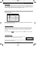
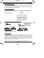
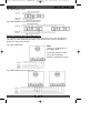
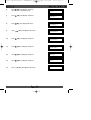
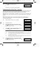
21/07/2007
11:53
TM
Eurosec eng LCD PR5203_15 5INEULCDIM_D A5booklet.qxd
CP8L LCD
I N S TA L L AT I O N
I N S T RU C T I O N S
Page 1
TM
Eurosec eng LCD PR5203_15 5INEULCDIM_D A5booklet.qxd
21/07/2007
11:53
Page 2
Eurosec eng LCD PR5203_15 5INEULCDIM_D A5booklet.qxd
21/07/2007
Contents
Introduction . . . . . . . . . . . . .
Display Status Blanking
Pre Setting Error Check
Battery Fuse . . . . . . . .
Mains Safety . . . . . . . .
Good Working Practice .
.
.
.
.
.
.
.
.
.
.
.
.
.
.
.
.
.
.
.
.
.
.
.
.
.
.
.
.
.
.
.
.
.
.
.
.
.
.
.
.
.
.
.
.
.
.
.
.
.
.
.
.
.
.
.
.
.
.
.
.
.
.
.
.
.
.
.
.
.
.
.
.
.
.
.
.
.
.
.
.
.
.
.
.
.
.
.
.
.
.
1
1
1
2
2
2
Installation . . . . . . . . . . . . . . . . .
Control Panel Location . . . .
Mounting the Control Panel
Mounting the RKP . . . . . . .
.
.
.
.
.
.
.
.
.
.
.
.
.
.
.
.
.
.
.
.
.
.
.
.
.
.
.
.
.
.
.
.
.
.
.
.
.
.
.
.
.
.
.
.
.
.
.
.
3
3
3
3
Wiring . . . . . . . . . . . . . . . . . . . . . . . . . .
General Detector Wiring . . . . . . . .
Wiring Global Tampers . . . . . . . . .
Wiring Contacts . . . . . . . . . . . . . .
Wiring Passive Infra-Red Detectors
General Bell Box Wiring . . . . . . . .
Bell Tamper Ring . . . . . . . . . . . . .
Sample Bell Box Connections . . . .
Wiring Notes . . . . . . . . . . . . . . . .
Control Panel Connections . . . . . .
.
.
.
.
.
.
.
.
.
.
.
.
.
.
.
.
.
.
.
.
.
.
.
.
.
.
.
.
.
.
.
.
.
.
.
.
.
.
.
.
.
.
.
.
.
.
.
.
.
.
.
.
.
.
.
.
.
.
.
.
.
.
.
.
.
.
.
.
.
.
4
4
4
4-5
5
6
6
6-7
8
8
Programming . . . . . . . . . . . . . . . . . . . . . . . . . . .
Terminology . . . . . . . . . . . . . . . . . . . . . . . .
Engineer Programming Mode . . . . . . . . . . .
Engineer Access - Programming Zones . . .
Programming Exit / Entry Times - Quick Set
Programming Bell & Panic . . . . . . . . . . . . .
Programming PGM1 Output . . . . . . . . . . . .
Programming Reset & Keypad . . . . . . . . . .
Engineer Reset (After an Alarm) . . . . . . . . .
Anti Code Reset . . . . . . . . . . . . . . . . . . . . .
Resetting to Factory Defaults . . . . . . . . . . .
Log Mode (EN Only) . . . . . . . . . . . . . . . . . .
Changing Log Mode (Non EN Panels) . . . .
9
9
10
10
13
15
16
17
18
18
19
19
19
Troubleshooting . . . . . . . . . . . . . . . . . . . . . . . . . 20 - 21
Specifications . . . . . . . . . . . . . . . . . . . . . . . . . . . 22 - 23
System Details . . . . . . . . . . . . . . . . . . . . . . . . . . 23
Changing the Engineer Code . . . . . . . . . . . . . . 24
11:53
Page 3
Eurosec eng LCD PR5203_15 5INEULCDIM_D A5booklet.qxd
e u ro s e c
21/07/2007
11:53
Page 4
I n s t a l l a t i o n M a nu a l
Introduction
The eurosec control panel is supplied as a blank fronted end station complete with LCD RKP.
Up to 3 additional keypads may be fitted if required. The unit is fully programmable by the
installation engineer and comes pre-programmed with a set of factory defaults that will suit most
installations. Eight programmable zones are available on the CP8.
The Control Panel will have been supplied with either an icon style keypad or text style
keypad. Please follow the instruction relevant to your keypad style. Text commands will
be shown in brackets.
Icon style keypad
Text style keypad
Full
Part
Quick
Yes
No
Note: It may be required that an engineer has to be authorised by a user before access
to the engineer mode is granted.
Display Status Blanking
Depending on Control Panel installed, It may be a requirement that the Status (Set or Unset
display) of the security system is not displayed, Set or Unset Status will only be displayed for
ten seconds when the system is Set or Unset. The bottom line of the display will then be
blanked off.
If the Control Panel is non EN then all displays will be shown.“CHECK” will not be displayed.
Pre Setting Error Check
At the start of the setting procedure any non exit routes that are open
will show a fault tone. The display will show, for example:-
Exit Now ! . . .
Zone 3
If the fault clears within 20 seconds then the exit will begin, if not, the fault tone will continue
until a valid User code is entered.
Pa g e 1
Eurosec eng LCD PR5203_15 5INEULCDIM_D A5booklet.qxd
21/07/2007
11:53
Page 2
I n s t a l l a t i o n M a nu a l
e u ro s e c
IMPORT
IMPORTANT!
Input:
AC230V +/-10% ~50Hz 125mA Max. 35W Max
For Indoor Use Only
Nominal Temp Range:
0° - 50° Centigrade
This equipment is intended only for use as a Security Alarm Control Panel.
Adequate ventilation away from heat and humidity must be provided. The unit
must be fixed securely to a non-flammable surface using suitable fixings.
All mains wiring must be to the relevant current IEEE wiring regulations (or appropriate
international regulatory standards). See relevant section within this manual for connection to
mains supply.
Provision is provided for an earth connection within the mains connection block, this is for the
protection of the wiring and is not a functional part of the unit.
All low voltage (alarm) wiring must be to the appropriate international regulatory standards and
comply to good wiring practice.
Replacement fuses should be of the same type and rating conforming to IEC127.
The maximum current draw from the unit for all output combinations must not exceed 1*Amp.
(See page 23 for further information).
The unit is intended for use with a suitable re-chargeable battery permanently connected to the
appropriate terminals.
Battery Fuse
An in-line Battery Fuse has now been incorporated into this product. The fuse rating is 2 Amp
Anti-Surge. The fuse holder is spring loaded, therefore you should ensure that the battery lead
is not under tension in order to maintain a good connection between the fuse and the holder.To
change the fuse, push the two halves of the holder together and twist anti-clockwise. Please
ensure correct battery charge on completion of the installation and during each service visit.
Mains Safety
The main unit must be connected to a mains supply via a 3 Amp unswitched fused spur. This
must be carried out by a suitably qualified electrician. If you are in any doubt please contact your
local electricity company for advice.
Good Working Practice
The reliability of any security system may be greatly enhanced by following a few good working
practices. Do not connect the mains supply to any rings that have fridges, freezers or
fluorescent lights connected to them. When running low voltage alarm cables, avoid running
parallel to mains wiring, if you do so, separate by a least nine inches. When crossing mains
cables, do so at 90°
Pa g e 2
Eurosec eng LCD PR5203_15 5INEULCDIM_D A5booklet.qxd
21/07/2007
e u ro s e c
11:53
Page 3
I n s t a l l a t i o n M a nu a l
Control Panel & RKP Location
Consideration needs to be given to the location of the Control Panel & LCD RKP with regards
toThe surface that the unit(s) are to be fixed to should be firm, vibration free, damp free and fire
resistant.
Access for the routing of mains and low voltage wiring.
Service Access to the unit(s).
Operation of the keypad.
Readability of the LCD RKP display(s).
Mounting the Control Panel
Unscrew the two cover retaining screws and remove the front cover.
The PCB is held in place by two lower PCB retaining lugs and two upper sprung latches.
Push both upper latches upwards and pull the PCB forward and upward in one movement.
With the PCB removed from its retainers offer the unit to the wall and mark for the three fixing
points. Under no circumstances should you drill through the base.
Remove any knockouts that are required from the base and also the cover screw caps from
the moulding pips in the base and retain them for use after fixing the front cover in place.
Using suitable rawl plugs and 3 No.8 x 1.5” (min) screws fasten the base to the wall but do
not tighten until all cabling is in place.
Mounting the RKP
Lower the front cover of the RKP and unscrew the single cover fixing screw.
Offer the RKP base to the wall and mark the three fixing positions. Under no circumstances
should you drill through the base.
Remove one of the cover screw caps and retain for use after fixing the front cover.
Using suitable rawl plugs and 3 No.6 x 1” (min) screws fasten the base to the wall offering
the connecting cable through a suitable aperture in the base as you do so.
Wire the LCD RKP as shown in the wiring section of this manual.
Replace the cover and tighten the cover fixing screw.
When finished put the cover screw cap in on the cover screw and push into place.
Pa g e 3
Eurosec eng LCD PR5203_15 5INEULCDIM_D A5booklet.qxd
21/07/2007
11:54
Page 4
I n s t a l l a t i o n M a nu a l
e u ro s e c
General Detector Wiring
We would strongly suggest that you adopt a colour scheme for the detector wiring of your
system. This will enable you to quickly determine the source of any problems that may occur.
The security industry does not have recommended colour schemes because of the nature of
the wiring, one suggested scheme is given below.
Wiring Global Tampers
One pair of tamper terminals is provided on the control panel PCB for tamper protection of the
zones. This is termed as a Global Tamper, one simple method of wiring Global Tampers is
shown in Fig. 1 below.
Fig. 1 Wiring Global Tampers
Wiring RKP Zones (480 text RKP ONLY)
RKP
Zone 12V
0V
D1
RKP
D2
Zone 12V
3K3
5K6
0V
D1
2K2
5K6
+ Power -
Alarm N/C
Tamper N/C
+ Power -
1st Detector
Alarm N/C
D2
Note: Keypad zones (480
text RKP ONLY) are preset
and cannot be changed.
E/E - 3K3 KP Zone 1
Access - 5K6 KP Zone 2
EOL - 2K2
3K3
2K2
Tamper N/C
2nd Detector
+ Power -
Note: Both detectors must be run on a single cable
from the Control Panel to the first detector
then the second. The 2K2 resistor must be in the
last/final detector.
Alarm N/C
Tamper N/C
2nd Detector
Alarm
Door Contact
Wiring Contacts
Many types of contacts are available and fall in to two categories, surface or flush. The method
of operation is the same for both. One half of the contact is fitted to the door or window frame,
inside is a reed switch that is pulled together in the presence of a magnetic field. The other half
that is fitted to the opening section of the door or window contains the magnet. These devices
are referred to as normally closed (NC or N/C). The gap allowed for reliable operation will vary
(usually between 5mm & 20mm) dependant on the model used, you should check this
specification with your supplier before fitting.
In Figs. 2 & 3 we have used 5 screw surface contacts for clarity of the illustration.
Pa g e 4
Eurosec eng LCD PR5203_15 5INEULCDIM_D A5booklet.qxd
e u ro s e c
21/07/2007
11:54
Page 5
I n s t a l l a t i o n M a nu a l
Fig. 2 Wiring Single Contact
Fig. 3 Wiring Double Contact (on the same zone)
Wiring Passive Infra-Red Detectors
It is essential when using Passive Infra-Red Detectors that you refer to the manufacturers
instruction as to the positioning and settings of the detector. This section is intended as a
guide to the wiring of the detectors.
Fig. 4 Wiring Single PIR
Notes
Positions of terminals will vary
according to make.
All PIR wiring diagrams apply
also to Dual Technology
Detectors and Vibration sensors.
Fig. 5 Wiring Double PIR (on same zone)
Pa g e 5
Eurosec eng LCD PR5203_15 5INEULCDIM_D A5booklet.qxd
21/07/2007
I n s t a l l a t i o n M a nu a l
11:54
Page 6
e u ro s e c
General Bell Box Wiring
As with the detector wiring we would suggest that you adopt a standard for your Bell Box wiring,
the colour scheme below is provided as a suggestion only.
Hold Off Supply +................. Red
Hold Off Supply - .............. .. Black
Trigger................................... Blue
Tamper Return...................... Yellow
Strobe +................................ Green
Strobe -................................. White
Bell Tamper Ring
It should be noted that many bell boxes that are fitted with rechargable batteries will sound when
the battery is connected. This connection may take the form of manually connecting the battery
wires to terminals or placing a link into the On position. Depending on the bell box being used,
the sounder may sound when the battery is connected unless power from the control panel is
connected or the bell box tamper is closed or in some cases both. Most bell boxes produce
high volume noise adequate ear protection MUST be used.
Sample Bell Box Connections
Below is shown general and sample bell box connections for some of the popular bell boxes that
are available.
General bellbox
Fig.6A
Fig.6B
connections
eurosec control
panel terminals
SAB TMP
Tamper Return
Bell Hold -
Supply -
Bell Bell +
Strobe Strobe +
Control
panel terminals
Tamper Feed
SAB TMP
TMPR
Bell Hold -
0V
Bell -
S-
Bell +
12v
Bell Trigger
Supply +
Strobe -
Strobe -
Strobe +
STCheck bellbox
terminal positions
Check bellbox
terminal positions
Fig.6C
eurosec control
panel terminals
XS3D / XS7
bellbox connections
Fig.6D
eurosec control
panel terminals
Delta E, Novagard 1E & 6
bellbox connections
Novagard 2&4
bellbox connections
F Tamper Feed
TMP-F
SAB TMP
R Tamper Return
SAB TMP
R-TMP
Bell Hold -
-12v Supply
Bell Hold -
0V
Bell -
Bell SW-
Bell -
S-
Bell +
+12v Supply
Bell +
12V+
Strobe -
ST-
Strobe +
Strobe -
Strobe Strobe +
Check bellbox
terminal positions
Check bellbox
terminal positions
Pa g e 6
Eurosec eng LCD PR5203_15 5INEULCDIM_D A5booklet.qxd
21/07/2007
e u ro s e c
Fig.6E
eurosec control
panel terminals
SAB TMP
Bell Hold Bell Bell +
Fig.6F eurosec control
CQR Integra HS
bellbox connections
Common
(Select AT Return)
panel terminals
SAB TMP
C
Bell Hold -
D
Bell -
B
Bell +
A
Supply -VE
Siren Trigger -VE
Supply +VE
Check bellbox
terminal positions
Fig.6H eurosec control
panel terminals
SAB TMP
C&K Securiguard
bellbox connections
Tamper
Tamper
Bell Hold -
Supply -
Bell -
Trigger -
Bell +
Supply +
Strobe -
Strobe -
Strobe +
Strobe +
panel terminals
SAB TMP
A/T Ret Sig
Hold Off -ve
Bell -
Siren Trig
Bell +
Hold Off +ve
Strobe -
Fig.6J
eurosec control
panel terminals
Elmdene Prima
bellbox connections
T
A
Bell -
B
D
Bell Hold -
H-
Strobe -
Bell -
-R
Strobe +
Bell +
H+
Fig.6L
eurosec control
panel terminals
Volumatic Flashguard Extra
bellbox connections
SAB TMP
Tamp Out
Bell Hold -
Supply -
Strobe +
Strobe +
ST
Fig.6K
Bell +
Strobe -
Check bellbox
terminal positions
Check bellbox
terminal positions
Strobe -
E
Bell Hold -
Bell +
Bell -
ADE Sonnade
bellbox connections
SAB TMP
TR
eurosec control
panel terminals
Strobe Trig
Check bellbox
terminal positions
SAB TMP
Strobe -
CQR Cequra
bellbox connections
Bell Hold -
Check bellbox
terminal positions
Fig.6Ieurosec control
S
STR -VE
-VE
eurosec control
panel terminals
Texecom Azura
bellbox connections
AT Return
Check bellbox
terminal positions
Fig.6G
Page 7
I n s t a l l a t i o n M a nu a l
Strobe Strobe -
11:54
TF
SAB TMP
BT
Bell Hold -
B-
Bell -
BA
Bell +
B+
Strobe -
Trigger -
Pyronix Decibell
bellbox connections
STB
Check bellbox
terminal positions
Supply +
Strobe -
Fig.6Meurosec control
Strobe +
panel terminals
Check bellbox
terminal positions
Eurosec EW1
bellbox connections
SAB TMP
RTN -
Bell Hold -
Hold Off -
Bell -
Trig -
Bell +
Hold Off +
Strobe -
STB Check bellbox
terminal positions
Pa g e 7
Eurosec eng LCD PR5203_15 5INEULCDIM_D A5booklet.qxd
21/07/2007
11:54
I n s t a l l a t i o n M a nu a l
e u ro s e c
Wiring Notes
Fig. 7 Control Panel Connections
D2
D1
0V
680 Ohm
+
Bell
+
+
N/C Detection Circuit
+
N/C Detection Circuit
AZ5
+
N/C Detection Circuit
AZ6
N/C Detection Circuit
+
AZ7
N/C Detection Circuit
+
AZ8
Pa g e 8
AZ4
Neutral
Blue
+
AZ3
N/C Detection Circuit
Live
Brown
Earth
Green/Yellow
AZ2
N/C Detection Circuit
RV 1
+
Fig. 8 Mains Terminal Block Connections
125mA Anti-Surge
Fuse
To Transformer
From 3A Fused Spur
+
AZ1
Please refer to the Wiring Global Tampers section
for details of wiring multiple tampers.
Multiple detectors fitted to a single zone should
have the alarm contacts wired in series. Please
see detector wiring section for more details.
Any N/O devices such as pressure pads should
be wired across the Global Tamper and the zone
required. The zone terminals should remain
shorted. When connecting the battery to the unit
please ensure correct polarity.
N/C Detection Circuit
TMP
N/C Global Tamper
Minimum impedance for Speaker is 16 Ohm
in any speaker configuration.
Blue
+
PGM1 sink current is 50mA
PGM1 is pulled high 1K pull-up resistor
AUX 12v
Aux Supply for
Detectors etc.
PGM1 +
SPKR
Panel speaker volume may be adjusted via RV1
on the Control Panel.
Display contrast may be adjusted via RV1 on the
RKP.
Hold- TMP
Programmable Output
for detectors requiring
switched signals
- Bell SAB
N/C Bell Tamper
Max Output current for Bell is 500mA.
REMOTE KEYPAD
D1
0V
12V
-
Strobe
Max Output current for Strobe is 250mA.
+
Maximum current draw from the panel MUST
NOT EXCEED 1Amp*. (See Page 23 for further
information). This includes all Bells, Sounders,
only if 480 (text)
Speakers, Detectors & RKPs etc. Battery 2K2
RKP zones not used
recharge current must also be taken into
consideration.
D2
2K2
Remove 2K2
if using Keypad
zones. (See Fig 5,
page 5).
12V Zone
2 x RKP zones only on 480 (Text) RKP
RKP
The 680 Ohm resistor (provided) must be
fitted across 12v & D1 at the last RKP in line.
Brown
Page 8
Eurosec eng LCD PR5203_15 5INEULCDIM_D A5booklet.qxd
e u ro s e c
21/07/2007
11:54
Page 9
I n s t a l l a t i o n M a nu a l
Terminology
Various terms are used throughout this manual that may be unique to the eurosec control
panel. This section gives brief details of this terminology.
Zones
12Hr
A zone programmed as 12Hr is active when
the system is set.
E/E
Entry/Exit Zone. If violated when the system is
SET will start the Entry Time. May also be
used to terminate the Exit Time dependant on
the Setting Mode being set to E/E or Time+
E/E.
Access
An Access Zone will allow violation during Exit
or Entry mode. Violation at other times will
result in instant alarm.
Panic
24Hr protection for devices such as Panic
Buttons etc.
24Hr
A 24Hr Zone will give internal speaker if
violated when the system is unset or full
sounders when set.
Fire
Active 24Hrs when violated gives internal
speakers + Pulsed External.
System
ET
Exit Terminator (Button).
E/E
Entry/Exit (Timed/Zone).
Part Set
Sounders
Sounder Mode during
Part-Setting.
Alert Keys
Pressing keys 1&3
simultaneously.
SAB
Self Actuating Bell.
SCB
Self Contained Bell.
Reset
To return panel to normal
after an alarm.
Alert
Internal Speaker only.
ET
Exit Terminator. Will terminate the Exit Time
provided Setting Mode is set to E/T.
Part E/E
Will act as Entry/Exit whilst part-set.Will act as
Access at all other times.
Zone Modes
Biased Keyswitch
Available for zone 5 only. Will Set/Unset the
system.
Part 1, Part 2, Part 1&2
Zones set as a particular Part-Set will be
omitted when that Part-Set is used. Part 1&2
refers to Part-Set 3
Chime
Zones set as Chime will chime when violated
with the system unset.
Engineer Code Code that allows the
installation engineer to
program and use the
system.
User Code
Code that allows end
user(s) to operate the
system. Up to nine users
may be programmed onto
the system.
Confirm
Confirmation of successful
setting via the strobe light.
Pa g e 9
Eurosec eng LCD PR5203_15 5INEULCDIM_D A5booklet.qxd
21/07/2007
11:54
I n s t a l l a t i o n M a nu a l
Engineer Programming Mode
Page 10
e u ro s e c
Several options are available via the Engineer code (1234 factory default). These are
a)
Setting and Unsetting of the system.
b)
Engineer/User Options
System Test
Program Code
c)
Delete Zone(s)
Set Time/Date
Chime On/Off
View Log
Program Engineer Options
Details of items a and b are given in the User manual. Please refer to it when
programming these modes. It should be noted that when programming the code from
engineer mode, it is the engineer code that is being programmed, no option for user codes is
given. If the engineer code begins with a 9, the code will be locked and may only be changed
by re-use of the code. Re-setting the system will have no effect.
IMPORTANT INFORMATION
To achieve EN compliance this Control Panel may only be used with
newer RKPs that have V1.8 or above firmware. The firmware version
will be shown on the display on power-up.
This section gives step by step instructions on programming the system. Please ensure that you
understand each option before making any changes.
Engineer Access - Programming Zones
In order to access Engineer Mode the User MUST start to set the system, then the Engineer
must enter the Engineer code TWICE.
When programming a non EN control panel, the Engineer does not require User
authorisation to gain access to Engineer mode. Go straight to step 5.
01 Jan
00:29
1)
With the display showing:Enter the User code (default 5678).
2)
The display will show:-
3)
Press
4)
Before the exit tone stops, enter the Engineer Code.
(1234 default). The display will show:-
01 Jan 00:29
<<<
UNSET
5)
Enter the Engineer code again. The display will show:-
Do You Want to . .
Set Engineer ?
Do You Want to . .
Set User 1 ?
(Yes). The display will show:-
Pa g e 1 0
Exit Now ! . . .
Ok !
>>>
Eurosec eng LCD PR5203_15 5INEULCDIM_D A5booklet.qxd
e u ro s e c
21/07/2007
11:54
Page 11
I n s t a l l a t i o n M a nu a l
6)
Press
(No). The display will show:You are now in Engineer mode.
7)
Press
8)
Press
9)
Press
10)
Press
(No). The display will show:-
Do You Want to. .
Program Codes ?
11)
Press
(No). The display will show:-
Do You Want to. .
Set Date / Time ?
12)
Press
(No). The display will show:-
Do You Want to. .
View Log ?
13)
Press
(No). The display will show:-
Program . . . . . . .
Zones ?
14)
Press
(No). The display will show:-
(No). The display will show:-
(Yes). The display will show:-
(Yes). The display will show:-
Pa g e 1 1
Do You Want to . .
Test ?
Do You Want to. .
Delete Zone ?
Do You Want to. .
Select Options ?
Do You Want to. .
Program Chime ?
Select
1..8
Eurosec eng LCD PR5203_15 5INEULCDIM_D A5booklet.qxd
21/07/2007
11:54
I n s t a l l a t i o n M a nu a l
15)
Page 12
e u ro s e c
Select a number corresponding to the zone you wish
to program. The display will show, for example:-
16)
Press (No) until the required zone type is displayed.
Note: Please see page 9 for zone terminology.
17)
Press
(Yes). The display will show, for example:-
Zone 1 Type
E/E
Zone 1 Mode
Chime
Note: Zones required to be off in a particular Part Set and to chime in a unset
condition select from one of the following:Options available
Chime
Zone will
Ch/P1
Zone will
Ch/P2
Zone will
Ch/P3
Zone will
Full
Zone will
Part 1
Zone will
Part 2
Zone will
Part 3
Zone will
chime in Unset.
chime in Unset but will be omitted in Part Set 1.
chime in Unset but will be omitted in Part Set 2.
chime in Unset but will be omitted in Part Sets 1, 2 & 3.
not chime & is not omitted in any Part Set.
be omitted in Part Set 1.
be omitted in Part Set 2.
be omitted in Part Sets 2 & 3.
18)
Press
19)
Press
20)
To accept the text shown press
(Yes) or to
change the text press
(No). The display will show,
for example:-
21)
Text may now be entered as you would on a mobile
telephone. The key allocation is shown below.
1
3
5
7
9
=
=
=
=
=
(No) until the required zone mode (chime & part set attribute) is shown.
(Yes). The display will show, for example:-
ABC
GHI
MNO
STU
YZ blank
2
4
6
8
0
=
=
=
=
=
Zone 1 Text
Zone 1
Zone 1 Text
-
DEF
JKL
PQR
VWX
1234567890
After a character is selected press
(Yes) to move on to the next.
Up to 16 characters may be entered as a zone descriptor.
22)
As the last character is entered, the programming will
jump to the next zone. Repeat from step 16 until all zones
have been programmed. To escape press 0. The display
will show:-
Pa g e 1 2
Program . . . . . . .
Zones ?
Eurosec eng LCD PR5203_15 5INEULCDIM_D A5booklet.qxd
21/07/2007
e u ro s e c
23)
Press
11:54
Page 13
I n s t a l l a t i o n M a nu a l
(No). The display will show:Program . . . . . . .
Entry / Exit
or
Press 0 twice to escape out of Engineer Mode.
Programming Exit / Entry Times - Quick Set
Two entry times are available (Entry Time 1 & Entry Time 2). On entry to the premises via the
entry door, the Entry Time 1 will start. If deviation from the entry route during entry time 1
then entry time 2 starts. Bells will not activate until Entry Time 1 has expired.
Note: Entry Time 1 is programmable to a maximum of 45 seconds (30 seconds default). If an
attempt is made to enter a time greater than 45 seconds the maximum (45 seconds) will be
entered.
Note: Exit times. Full Set, Part 1, Part 2 & Part 3 exit times have a minimum times of 3
seconds. If an attempt is made to program a time less than 3 seconds the minimum
(3 seconds) will be entered.
With the display showing:- Press
25)
The display will show:-
F - Exit Time
30
26)
Default Full Set Exit Time is 30 seconds. To change,
press No followed by time required. Then press
(Yes). The display will show:-
F - Exit Mode
Time
Press
(No) until the required Exit Mode is displayed
followed by
(Yes). The display will show:-
P - Exit Time
30
27)
(Yes).
Program . . . . . . .
Entry / Exit
24)
Options available
Time
The system will Set after the time shown in the exit time.
28)
T/EE
Once the user has started to Set the system the system will set on either the time expiring or the
door opening and closing. This option may require a door contact.
ET
The system will set when the Exit terminator Button is pressed (this option will require a Zone to
be programmed as Exit Terminator).
E/E
Once the user has started to Set the system the Exit tones will continue until the final exit door is
opened and closed. This option will require a door contact.
Default Part Set Exit Time is 30 seconds. To change,
press (No) followed by time required. Then press
(Yes).The display will show:-
Pa g e 1 3
P - Exit Mode
Time
Eurosec eng LCD PR5203_15 5INEULCDIM_D A5booklet.qxd
21/07/2007
11:54
I n s t a l l a t i o n M a nu a l
29)
Page 14
e u ro s e c
Press (No) until the required Part Set Exit Mode is
displayed. Then press
(Yes). The display will show:-
P - Exit
Aud.
Sounder
30)
Press (No) until the required Part Set Sounder Mode
is displayed. Then press
(Yes). The display will show:-
Confirm Mode
Off
31)
The Confirm Mode relates to strobe confirmation.
Press (No) until the required setting is displayed. Then
press
(Yes). The display will show:-
Quick-Set
Off
Note: In previous CP8L versions it was possible to turn off the (Quick) key
function either from the engineer programming or by a power-on reset. The power-on
reset has been removed and if the (Quick) key function needs to be turned off/on
(default off) it must be done from the Engineer programming mode.
32)
Press (No) until the required setting is displayed. Then
press
(Yes). The display will show:- (Default 30
seconds).
33)
Default Entry Time 1 is 30 seconds. To change, press
(No) followed by the time required. Then press
(Yes).
The display will show:-
Entry 2 Time
10
Default Entry Time 2 is 10 seconds. To change, press
(No) followed by the time required. Then press
(Yes).
The display will show:-
F - Exit Time
30
34)
Entry 1 Time
30
Note: Entry procedure is; Open entry door, entry time 1 starts. Entry time 1 runs to
the programmed time or until there is a deviation from the entry route. Then Entry
Time 2 starts, at the end of Entry Time 1 the bells will be activated.
35)
Press 0 to escape back one level. Then press
to the next Header. The display will show:-
(No) to go
or
Press 0 three times to escape out of Engineer Mode.
Pa g e 1 4
Program . . . . . . .
Bell & Panic ?
Eurosec eng LCD PR5203_15 5INEULCDIM_D A5booklet.qxd
21/07/2007
e u ro s e c
11:54
Page 15
I n s t a l l a t i o n M a nu a l
Programming Bell & Panic
36)
With the display showing:- Press
(Yes).
37)
The display will show:-
38)
Default Bell Time is 10 Minutes. To change, press
(No) followed by the required time.
Program . . . . . . .
Bell & Panic ?
Ring
10
Time
Note: Bell ring time is programmable to a maximum of 15 minutes The minimum
time allowed is 1 minute.
Then press
39)
Press
(Yes).The display will show:-
Bell
00
Delay
(No) followed by the delay required.
Note: Be careful when using Bell delay, the bell will not sound for the period
programmed after the alarm has been activated. Bell Delay used to be a Police
requirement but is now not often used in the UK. It should only be
programmed on systems that are fitted with communications devices.
40)
Then press
(Yes). The display will show:-
Bell
99
Re-Arms
Note: Re-Arms is the number of times the bell is capable of sounding during a Set
period. It is normal to set this option to 3 or 4. If left at 99 the number of Arms is
infinite.
41)
Press (No) followed by the number of Bell Re-Arms.
Then press
(Yes). The display will show:-
Bell
SAB
Mode
Two Types of Bell may be programmed.
SAB
Self Actuating Bell. The Bell + terminal stands at 12V and the Bell -terminal switches
negative on activation.
SCB
Self Contained Bell. The Bell + and Bell - stand at 12V and 0v. The 0V is removed on
activation.
The majority of Bells sold in the UK are SAB. You should only change the Bell Type if
you are sure the Bell Type you have is SCB.
Pa g e 1 5
Eurosec eng LCD PR5203_15 5INEULCDIM_D A5booklet.qxd
21/07/2007
11:54
I n s t a l l a t i o n M a nu a l
Page 16
e u ro s e c
42)
Press (No) until the required Bell Mode is displayed.
Then press
(Yes). The display will show:-
43)
44)
Tamper
Off
Ring
Press
(No) to set the Bell Tamper Ring Mode On or Off.
Then press
(Yes). The display will show:-
Panic
Aud.
Mode
Press
(No) until the required Bell Panic Mode is
displayed. Then press
(Yes). The display will show:-
Ring
10
Time
Note: Silent (Sil) should only be programmed on systems that are fitted with
communications devices.
45)
Press 0 to escape back one level. Then press
to the next Header.The display will show:-
(No) to go
Program . . . . . . .
Outputs & Digi?
or
Press 0 three times to escape out of Engineer Mode.
Programming PGM 1 Output
PGM 1 refers to the PGM1 terminal on the control panel PCB.
46)
With the display showing:- Press
(Yes).
47)
The display will show:Press
(No) until the required mode is displayed for
PGM1.
Program . . . . . . .
Outputs & Digi?
PGM
SW12V
1 Mode
Options available
SW12V
Normally used for latching sensors.
PulsWill stand at +12V and switch to 0V for three seconds when the user code is entered.
Bell
Will switch when the Bell is activates.
Strobe
Will switch when the Strobe activates.
Ex/En
Will switch when the Entry/Exit time starts.
Walk
Will switch when in walk test.
IntAl
Will switch when a tamper alarm activates.
Alarm
Will switch when the Alarm activates.
Panic
Will switch when Panic activates.
Puls+
Will switch for 3 seconds when the User code is entered.
48)
Then press
(Yes). The display will show:-
Note: Digi programming is no longer applicable on this Control Panel.
Pa g e 1 6
Chan.1
Fire
Mode
Eurosec eng LCD PR5203_15 5INEULCDIM_D A5booklet.qxd
21/07/2007
e u ro s e c
49)
11:54
Page 17
I n s t a l l a t i o n M a nu a l
Press 0 to escape back one level. Then press
to the next Header. The display will show:-
(No) to go
Program . . . . . . .
Reset & Keypad ?
or
Press 0 three times to escape out of Engineer Mode.
Programming Reset & Keypad
50)
With the display showing:- Press
(Yes).
51)
The display will show:-
Tamper
Any
Reset
52)
Press (No) until the required Tamper Reset Mode is
displayed. Then press
(Yes). The display will show:-
Alarm
Mast
Reset
53)
Press (No) until the required Alarm Reset Mode is
displayed. Then press
(Yes). The display will show:-
Service
99
Time
54)
Press (No) followed by the required number of weeks
for the Service Timer. Then press
(Yes).
(Note 99 = Off). The display will show:-
Alert
Panic
Mode
55)
Press (No) until the required Alert Mode (Keys 1&3)
is displayed. Then press
(Yes). The display will show:-
Tamper
Any
Reset
56)
Press 0 to escape back one level. The display will show:-
Program . . . . . . .
Reset & Keypad ?
57)
Press 0 twice. The display will show:-
This concludes the system programming.
Pa g e 1 7
Program . . . . . . .
Reset & Keypad ?
01 Jan 16:49
Eurosec eng LCD PR5203_15 5INEULCDIM_D A5booklet.qxd
21/07/2007
11:54
I n s t a l l a t i o n M a nu a l
Page 18
e u ro s e c
Engineer Reset (After an Alarm)
If the Reset Mode(s) has been programmed for Engineer follow the steps below to reset the
system.
1)
The user must first unset the system. Details in User manual.
2)
Enter the engineer code followed by RESET.
It should be noted that if the Tamper reset has been programmed for Engineer Reset the
display will show:! !
Service Due
!
for 10 seconds each time the user attempts to set the system. The procedure as shown
above is used to Reset this condition.
Anti-Code Reset (After Alarm or Service Timer Lockout)
To effect an Anti-Code Reset the engineer will require either a Anti-Code Generator or
Anti-Code Software running on a P.C.
1)
Ask the customer to enter the user code and then press
(Yes).
2)
A four digit seed code will be shown by the display.
3)
Enter this seed code into either the Generator or P.C. Software. An Anti-Code will be
given.
4)
Ask the customer to enter this Anti-Code. The system is now reset.
Note: Service Timer Lockout will have been indicated to the user. Two weeks notice would have
been given prior to Lockout. Resetting this via Anti-Code will give another two weeks service. A
service visit should be arranged and the Service Timer should be re-programmed to the
required number of weeks.
Pa g e 1 8
Eurosec eng LCD PR5203_15 5INEULCDIM_D A5booklet.qxd
21/07/2007
e u ro s e c
11:54
Page 19
I n s t a l l a t i o n M a nu a l
Resetting to Factory Defaults
If required the unit may be reset to factory defaults. It should be noted that if the engineer
code begins with a 9 it will not be defaulted.
1)
Remove all power from the system.
2)
Wait 10 seconds.
3)
Re-Apply power to the system.
4)
As soon as the display becomes active enter 1 4 7
(No).
Log Mode
The log may store 256 events with time and date stamp and cannot be changed (EN only).
Note:
If programming a non EN control panel, the Log modes may be changed.
Please follow the steps outlined below.
Changing Log Modes (Non EN Panels only)
a)
256 events without Time & Date stamps
or
b)
64 events with Time & Date stamps (Default setting)
To change the Log Mode:1)
Remove all power from the system.
2)
Wait 10 seconds.
3)
Re-Apply power to the system.
4)
As soon as the display becomes active enter 0 0 7
(No). For 256 events.
or
As soon as the display becomes active enter 9 1 7
Note:
(No). For 64 events.
When the Log Mode is changed the message ‘ L/ Rst ‘ will be added to the
Log.
Pa g e 1 9
Eurosec eng LCD PR5203_15 5INEULCDIM_D A5booklet.qxd
21/07/2007
11:54
I n s t a l l a t i o n M a nu a l
Page 20
e u ro s e c
Action
Fault
Control Panel will not power up from the
mains supply.
Check / replace fuse in fused spur or mains
connection block. Also check all connections
for trapped insulation.
Display shows zone fault and panel will
not set after the exit time has expired.
Remove zone wires from the problem zone at
the control panel and replace with a link.
Check if panel now sets. If all is O.K. the
problem is external to the control panel. Check
with a multimeter the continuity of the wires
you removed from the zone. Also check that
there is no short circuits between the zone
wires and the tamper loop or the zone wires
and 0v (Earth).
Control Panel gives tamper fault.
Check Lid tamper spring on control panel.
Link out the tamper loops (bell & global) to
determine what tamper loop the fault is on. If
all is O.K, the problem is external to the panel.
Using a multimeter check for continuity and
also short circuits to other cores in the same
cable. Also check that the service timer has
not expired.
Tripping a detector does not cause an
alarm and is not registered at the control
panel.
Check for short circuits on the zone wiring. If
two detectors are fitted to the same zone try
tripping both of them at the same time, if the
zone activates when this is done the alarm
contacts of the detectors have been wired in
parallel when they should be wired in series.
External Sounder does not sound.
Use a multimeter or small buzzer across the
Bell +&- terminals to determine if the control
panel is triggering the bell. If all is O.K check
the operation of the sounder by wiring it to the
system battery.
External Sounder rings without the control
panel triggering it.
Disconnect the Nicad battery from the SAB of
the sounder. Check to see if the hold off
voltage is present at the sounder, if not
check/replace the control panel fuse. If fuse is
O.K check hold off voltage at the control
panel. If hold off voltage is O.K check/replace
the wiring to the bell.
Bell Box will not sound after first power
up.
Some Bell Boxes require all tampers to be
closed before they will sound. Close all
tampers and retry.
Pa g e 2 0
Eurosec eng LCD PR5203_15 5INEULCDIM_D A5booklet.qxd
e u ro s e c
21/07/2007
11:54
Page 21
I n s t a l l a t i o n M a nu a l
Action
Fault
Tamper is not tripped when a detector
cover is removed.
Check to see if all tampers are wired in series.
If detector tampers have been wired in parallel
they will all have to be removed before the
tamper would trigger. Check for short circuits
that may occur through staples piercing
cables.
Detectors false alarm.
Check that the position of the detectors is in
accordance with the manufacturers
recommendations.
In the case of a PIR ensure that the unit is not
facing a window or is situated in a draughty
location.
In the case of a contact check the gap
between the two halves and that there is no
excessive movement in the protected item.
In the case of a shock sensor ensure it is not
bridging any joints.
Check cable runs to ensure that they are not
running parallel to any mains wiring (see good
wiring practice).
Engineer and/or User codes have been
forgotten.
The panel may be reverted to factory defaults
(see Resetting to Factory Defaults). If the
engineer code has been programmed with 9
as the first digit it will not be defaulted. In this
case the unit must be returned to the factory.
I got confused whilst programming and
don’t know what settings have been
programmed.
In this situation we would recommend that you
revert to factory defaults.
I have various problems and think the
control panel is faulty.
This is rare, the majority of faults are usually
external to the control panel. If you think the
panel is faulty please remove all the wiring
from the panel and replace all the factory fitted
links then check the panel again.
Pa g e 2 1
Eurosec eng LCD PR5203_15 5INEULCDIM_D A5booklet.qxd
21/07/2007
11:54
I n s t a l l a t i o n M a nu a l
Page 22
e u ro s e c
Specifications
Power Input:
230v a.c +/- 10% @50Hz
No. of Zones:
CP8 = 8 LCD (+ 2 RKP Zones if 480 Text RKP used).
Max Loop Resistance:
2K Ohms
Loop Delay Time:
400 milliseconds
Fuses:
Mains Fuse:
F2 Misc Fuse:
F1 System Fuse:
Battery Fuse:
125mA slow blow
250mA quick blow
1A quick blow
2A Anti-Surge.
Low Voltage Output:
13.8v (typical) Regulated
Power Supply Rating:
1A*
Battery Sizes:
12v 1.2Ah, 2.0Ah, 3.0Ah & 7.0Ah
Quiescent Current:
Control Panel:
RKP:
50mA
40mA
Complies With:
EN50131-1 PD6662 2004 CE tested
Conforms With:
EMC Directive 89/336/EEC
LVD Directive 73/23/EEC
Log Size:
256 (Time & Date stamped - EN Only)
256 Events (No Time & Date stamp)
or
64 Events (Time & Date stamped - Non EN Panels)
Default Codes
Engineer:
Master User:
1234
5678
Number of Codes:
1 Engineer
9 Users on preset levels
Display Type:
32 Character LCD (2 x 16)
Method of Operation:
Remote Keypad(s)
PGM 1
PGM1 terminals are an open collector output held at 12V
through an integral 1k resistor. Max current sink into PGM
1 terminals is 50mA.
Pa g P
e a2g2e 2 2
Eurosec eng LCD PR5203_15 5INEULCDIM_D A5booklet.qxd
21/07/2007
e u ro s e c
11:54
Page 23
I n s t a l l a t i o n M a nu a l
*Power Supply Rating
It should be noted that the eurösec CP8L has 1 Amp available for the full system. However,
for the purpose of compliance to EN and PD6662 standard, the capacities of the power
supply have to be specified differently.
For a Grade 2 system you have 72 hours to charge the battery. With the CP8L Control Panel,
90mA is available for battery charging. This defines a theoretical maximum standby battery
capacity of 8.0Ah and a maximum of 666mA available for system power.
If a smaller capacity battery is used then the rating has to be reduced accordingly.
For example: If a 7Ah battery is used it will recharge in 72 Hrs and will theoretically provide
910mA (1000-90mA) for the system. However, the supply rating for that system under
PD6662 is still 7.0Ah/12hrs = 583mA.
Sounders, detectors and other auxiliary items should be included when calculating current
drawn by the system. Any damage caused through overloading the Control Panel Supply will
not be covered by the warranty. We recommend that additional power supplies are used to
supply detectors on long cable runs.
Customer Name
Customer Address
Tel No:
Fax No:
Installation Date
Installing Engineer(s)
Control Panel Location
RKP Location(s)
Zone 1 Location
Zone 5 Location
Zone 2 Location
Zone 6 Location
Zone 3 Location
Zone 7 Location
Zone 4 Location
Zone 8 Location
Pa g e 2 3
Eurosec eng LCD PR5203_15 5INEULCDIM_D A5booklet.qxd
21/07/2007
11:54
Page 24
Changing the Engineer code
The engineer code may only be changed by use of the current engineer code. If the engineer code
starts with a 9 the code will be ‘locked in’ defaulting the panel will have no effect on the engineer code.
To program the engineer code proceed as follows:In order to access Engineer Mode the User MUST start to set the system, then the Engineer must
enter the Engineer code TWICE.
When programming a non EN control panel, the Engineer does not require User
authorisation to gain access to Engineer mode.
1)
Enter the Engineer Code for the second time (1234 default),
followed by
(No). The display will show:-
Do You Want to. .
Test ?
2)
Press
(No). The display will show:-
Do You Want to. .
Delete Zone ?
3)
Press
(No). The display will show:-
Do You Want to. .
Select Options ?
4)
Press
5)
Press
6)
Press
7)
Press
8)
Enter the four digit code you require, followed by
The display will show:-
9)
Press 0 twice to return to the Unset condition.
(Yes). The display will show:-
Do You Want to. .
Program Chime ?
Do You Want to. .
Program Codes ?
(No). The display will show:-
Code
####
(Yes). The display will show:-
Code
0000
(No). The display will show:-
Pa g e 2 4
(Yes).
Do You Want to. .
Program Codes ?
Eurosec eng LCD PR5203_15 5INEULCDIM_D A5booklet.qxd
21/07/2007
11:54
Page 25
Supplied By:-
Technical Helpline
0161 655 5600
RISCO Group UK Ltd reserve the right to amend the software and features without prior notice
5INEULCDIM ver D
PR5203 Rev1.5