1
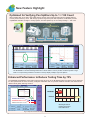
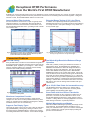
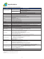
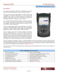
Product Brochure MT9083 Series MT9083A/B/C ACCESS Master™ 850/1300 nm OTDR for Multimode Fiber 780/1310/1383/1490/1550/1625/1650 nm OTDR for Single Mode Fiber All-in-One Solution that Reduces Testing Times to Install and Maintain FTTx, CATV, LAN, Access and Metro Networks 850/1300 nm OTDR for MMF 780/1310/1383/1490/1550/1625/1650 nm OTDR for SMF MT9083 ACCESS MASTER SERIES OVERVIEW Optical fibers are a key technology in today’s modern communications systems, including access networks such as FTTx, CATV, and optical LANs. Moreover, optical-fiber technologies are playing increasingly important roles in mobile communications and digital broadcasting systems. Technicians maintaining these diverse systems are forced to carry a large variety of test equipment on-site, including OTDRs, Light Sources, Optical Power Meters, Visible Light Sources, etc., as well as a notebook computer for evaluating the FTTx QoS. On the other hand, fiber construction requires measuring instruments with different functions and performance. As an example, FTTx access networks use single mode (SM) fiber whereas optical LANs use multimode (MM) fiber. In addition, core and backbone networks utilize long fibers while optical access networks use short fibers, both requiring different types of measuring instruments with different performance. But now Anritsu’s new line of MT9083 ACCESS Master OTDRs solves all these problems by providing all the measurement functions and performance required for optical fiber construction and maintenance in a compact, lightweight, all-in-one unit that eliminates the burden of carrying many different test sets and instruments on-site. Whatever your work, construction or maintenance, long haul or intra-building, Anritsu has an MT9083 model for your needs. ACCESS Master Key Features • Ready to test in about 15 seconds…and all day without recharging • Specialized testing modes simplify operation • High resolution and high dynamic range ensure quick and through fiber evaluation • Intelligent analysis software identifies problem splices, connectors and even macrobends • Rugged, sealed design provides years of service in the most challenging environments • IP testing option verifies throughput, frame loss and point-to-point connectivity • Test up to four wavelengths with a single unit - single mode, multimode or both • Unique in-service testing without the need for external filters • Verify connector quality with optional connector inspection microscope Full Scpi Command Support for Remote Operation or Automated Testing Multiple Models to Meet Any Testing Requirement • MT9083A: General purpose, good range, up to 38 dB. • MT9083B: High performance, enhanced range with full 1 × 64 PON support, up to 42 dB. • MT9083C: Ultra-high performance, enhanced range with full 1 × 128 PON support, up to 45 dB. MT9083 Series MT9083A/B/C ACCESS Master™ 850/1300 nm OTDR for Multimode Fiber 780/1310/1383/1490/1550/1625/1650 nm OTDR for Single Mode Fiber 2 New Feature Highlight Optimized for Verifying Pon Splitters Up to 1 × 128 Count Many OTDRs claim to be able to test splitter-based, passive optical networks (PON) but the MT9083 delivers in a way others wish they could. With its high dynamic range and quick data acquisition, the MT9083 provides unparalleled resolution of single or closely spaced, cascaded splitters up to an industry-leading 1 × 128 count. Up to 1 128 count CO Home Pedestal with splitter OLT Drop Cable Feed cable from Central Office 200 m Fig 1: Typical PON 1 × 64 count System Measurement from the customer premise. The MT9083B or C Enhanced Range Mode and a Pulse width of 100 ns provides excellent dynamic range while not compromising deadzone resolution to clearly display multiple, high loss splitters. Enhanced Performance to Reduce Testing Time by 75% The MT9083B and MT9083C series feature high dynamic range (up to 45 dB) allowing fibers over 200 km to be measured. It is also optimized at the most commonly used pulse widths like 100 ns to provide excellent resolution and measurement distance while greatly reducing test time. MT9083B/C (Enhanced Mode) 10 sec. MT9083A MT9083A Noise Floor MT9083B/C Noise Floor Measurement time: 10 sec 100 sec. 20 40 60 80 Wavelength: 1550 nm Distance range: 50 km Pulse width: 100 ns Fig. 2: Improved measurement range from MT9083A to MT9083B/C (100 ns shown) 3 100 120 (sec) Designed with the Features that Matter Most hen buying products, you tend to choose ones that are innovative and from established companies. When you need to install W and maintain optical networks, this should also apply. With over 50 years of combined OTDR design, Anritsu, delivers the features that matter. Having been in the test and measurement business for a long time, we understand that things like performance, portability, reliability, easy operation and of course price are important. Quick Startup Common OTDR Data Format The ACCESS Master is ready for measurement about 15 seconds after power-on so productive work can start immediately. The MT9083 supports the universal Telcordia SR-4731 (issue 2) format making it compatible with not only legacy Anritsu and NetTest products, but with many other vendors data. Long Battery Life Free and Simple Software Upgrades Since AC power is not always available where you need it, especially at fiber pedestals, the MT9083 typically provides up to 8 hours of operation on a single charge. This coupled with an optional car cord (for cigarette lighter operation) guarantees the MT9083 is ready when you are. Firmware upgrades are easily performed via USB and available from the Anritsu website for registered users or through Anritsu customer support. Active fiber check With its light weight design and user friendly dimensions, the MT9083 is perfect for the outside plant environment and can easily be managed with one hand. The shoulder strap (part of the protector option) further increases portability when travelling from the truck to the testing site. Not only can OTDR measurements be effected when the optical fiber is in-service but there is a potential risk of damage to the transmitter and OTDR receiver. To prevent these problems, the MT9083 verifies if light is present before starting measurement and will not transmit if it is. An on-screen warning and internal OTDR protection are also part of this useful feature. Rugged Integrated Macrobend Detection The MT9083 features a solid casework with no fans or vents to keep dust or moisture from entering the unit.In addition, the protector option (MT9083A/B/C-010) includes rubber bumpers and a display cover for additional protection from those minor mishaps. With many technicians making the switch from copper installations to optical fiber, installation issues such as macrobends are bound to occur. To help prevent this, Anritsu has developed a macrobend detection feature for the MT9083 that will alert technicians when a possible macrobend is present. This provides a higher quality of service for the customer and eliminates costly troubleshooting for you. Portable Generous Data Storage With the ability to store up to 1,000 traces in internal memory and up to 30,000 via a USB device, the MT9083 offers plenty of storage for collecting and managing data. Wavelengths for Today’s Networks Sometimes you just need more than the traditional 1310 and 1550 nm wavelengths to certify your next generation networks. The MT9083 offers a host of specialized wavelengths including 1383 nm for water peak verification of CWDM carrying fibers, 1650 nm (with integrated filter) for live fiber troubleshooting, 1490 nm for verification of voice, data and IP based video services and 780 nm for in-service troubleshooting of FTTx networks - without the need for any additional filters. No Experience Required With the ACCESS Master, the experience is built in. With specialized testing modes, automatic parameter selection, PASS/FAIL indicators as well as features to virtually eliminate the chance to get “bad” results, the MT9083 can make anyone seems like a 20 year veteran. Let it help you master your network. Easy “drag and drop” File Transfers When the MT9083 is connected to a PC via a USB cable, the internal memory of the ACCESS Master can be directly accessed. Data can be selected, dragged and dropped into the PC memory, greatly simplifying file transfers. The MT9083 also supports use of USB memory sticks. 4 Compact, Light Weight and All-in-one With its versatile built-in functions, the ACCESS Master offers the ideal solution for efficient optical fiber construction and maintenance. All-in-one Test Set The MT9083 delivers full featured OTDR performance plus loss test set and quality of service measurement in a surprisingly small and lightweight package. At only 28.4 cm wide × 20 cm tall × 7.7 cm deep and 2.2 kg (4.8 lbs.), it is field portable, yet rugged enough to withstand the outside plant environment. When equipped with power meter, visual light source and IP test options, it replaces several, larger pieces of test equipment. Up to 8 hours battery life plus quick recharge Numeric keypad with dedicated keys for easy operation Optical Power meter options with up to +30 dBm measurement range Dedicated function keys for selecting parameters Rotary dial for precision cursor movement Visible laser source for easy fiber identification and bend/ break location Arrow keys for quick zooming and navigation through menus Up to four wavelengths from a single port for any application Dual USB ports for easy data transfer and connector inspection microscope IP options for verifying QoS of 10/100/1000 MB links START key for simple one-button testing 6.5 inch color, TFT-LCD display with simple menus There are two types—a Standard type for indoor use, and an Enhanced type for use both indoors and outdoors 5 Exceptional OTDR Performance from the World’s First OTDR Manufacturer Evaluation of access networks ranging from a few kilometers to metro networks reaching up to 100 km in length is becoming commonplace, requiring OTDRs to have the performance and functions for evaluating both short and long fibers. Designed with this in mind, the ACCESS Master delivers on both fronts. Improved Short Fiber Analysis Extended Range Testing of 200 + km Fibers An event dead zone of less than 1 m (80 cm typical) and a sampling resolution of 5 centimeters allow the MT9083 to evaluate connections and troubleshoot central office, FTTx and intra-building faults with ease – providing a level of detail never before seen. In addition to its superb high-resolution performance, the MT9083 also features up to 45 dB of dynamic range allowing it to easily test 200 + km spans making it a very useful tool for any network type. Fig. 3: W ith its high resolution optics, the MT9083 provides exceptional detail allowing users to quickly determine where the problem is-even when events are closely spaced. Fig. 4: S pans of over 200 km are also easily tested making the MT9083 the only tool you will need - for any network type. Convenient Features Full PON Testing Dual-Mode High Resolution/Enhanced Range Operation Many OTDRs claim to be able to test PONs but being able to do it with both high resolution and high range is what sets the MT9083B/C apart. Splitters up to a single 1 × 128 or closely spaced, cascaded splitters are completely and accurately measured with industry leading resolution. While many OTDRs provide good deadzone resolution or high dynamic range, the MT9083A-073, MT9083B and MT9083C series features a dual-mode design that allows a single unit to excel in both categories. The user can simply select HIGH RESOLUTION (HR) mode or ENHANCED RANGE (ER) based on the current task at hand. When HR mode is selected, these modes provides good measurement range with an industry leading deadzone (<1 m). When ER mode is selected, they provides unparalleled performance for measurement distance, measurement speed and deadzone allowing a 100 km fiber to be tested in less than 10 seconds. ER mode is also used for testing PON networks with up to 128 branches. Up to 150,001 Data Points for Increased Accuracy The MT9083C series also collects up to 150,001 with a resolution of just 2 m. This provides the necessary detail when installing and maintaining fiber spans. Event Table with User Defined Thresholds Fig. 5: M T9083B and MT9083C series provides high range and excellent resolution of PON systems PASS/FAIL thresholds for key acceptance criteria such as splice loss, connector loss and reflectance can be set in the MT9083 allowing technicians to easily assess a fiber’s condition. Failing values are clearly highlighted in the event table alerting technicians of potential problems. Waveform Comparison Function Compare current and stored trace data to easily assess changes over time and to locate problems before they effect service or compare traces at different wavelengths to identify installation issues such as macrobending. Multiple Wavelengths and Models With nine available wavelengths spanning both single mode and multimode, the ACCESS Master MT9083 is sure to meet your individual needs. Up to four of these wavelengths can be combined into a single optical output providing full spectrum characterization. Supports Two Display Types There are two types of 6.5 inch, TFT color LCDs: the standard type (MT9083A/B/C), offering easy viewing for indoors, and the enhanced type (MT9083A1/B1/C1), offering easy viewing for working both indoors and outdoors - even in direct sunlight. 6 Solutions for Various Measurement Needs Products that offer many features are often complicated to use. The ACCESS Master however, simplifies operation by offering task-specific testing modes that automate testing and guide novice users. Dedicated testing modes are available for fault location, cable installation, loss budget testing, visual fault location and IP testing. Simple Operation NETWORKS PC Software for Analysis and Reporting To simplify testing, the MT9083 features dedicated measurement modes via the top menu to automate and simplify the task at hand. Once the data is collected, NetWorks PC emulation software makes analysis and report generation a breeze. Professional reports including splice loss, fiber acceptance and exceptions as well as various printing options are possible with only a few mouse clicks. Fig. 6: Dedicated measurement modes simplify testing for any skill level. Fig. 7: Comprehensive, professional reports are easily generated Fault Location Template Feature FAULT LOCATE mode is designed for the novice or someone who only uses an OTDR occasionally. Simply connect the fiber and press START. The unit will verify the fiber is connected correctly, select testing parameters and provide a text response indicating fault/break location - easy to read results for any skill level. To simplify fiber acceptance, the Access Master incorporates an on-the-fly template feature to quickly locate and measure all splices in a fiber cable. In addition, an on-screen highlight blocks out the expected splice locations during trace acquisition. General OTDR Testing For those who have more experience or would like to perform more advanced testing, STANDARD OTDR mode allows the user to set all parameters and compare traces manually, automatically or somewhere in between. Optical Fiber Construction and Certification When final cable acceptance is the task at hand, CONSTRUCTION mode greatly simplifies operation through its innovative wizard. Select the required testing wavelengths, number of fibers and file naming scheme and construction mode acts as the project manager guiding the user through the testing, while ensuring consistency with testing parameters and filenames - virtually eliminating user induced errors and missing files. Fig. 8: Template Mode Remote Command Support To simplify and automate testing in manufacturing and lab environments, the MT9083 supports SCPI commands. Through the use of a USB converter and a common scripting program such as LabViewTM, the MT9083 can be quickly integrated and immediately reduce testing times, Remote control can also be used for remote, unmanned monitoring applications. Value Whatever your construction or maintenance needs, the new ACCESS Master MT9083 is designed to reduce the time to install, commission and maintain your optical networks – without breaking your budget. 7 A True All-in-One Tester An OTDR, Optical Power Meter, Visible Light Source, and IP tester are built into Anritsu’s compact, light-weight MT9083 supporting tasks ranging from searching for faults in optical fibers to QoS evaluation to FTTx troubleshooting with just one unit. Complete Loss Test Set Features Standard Stabilized Light Source Data Table for Saved Results The OTDR port also functions as a stabilized light source providing continuous wave, 270 Hz, 1 kHz and 2 kHz modulations for easy fiber identification. This is standard equipment on all single mode models - a chargeable option on most other OTDRs. Loss test set measurements for multiple wavelengths can be saved into a results table for easy comparison and archiving. The table can also be saved as a text file and exported to a PC spread-sheet program for further manipulation or integration into a standard company template. Standard or Optional Integrated Power Meter Video Inspection Probe Support In the base unit, the OTDR port also functions as an integrated power meter for verification of optical power levels. Additional power meter options are available for higher power transmissions and loop-back testing. When equipped with the optional connector video inspection probe (VIP), the MT9083 becomes a powerful tool for evaluating connector cleanliness and quality. Connector end faces can be safely viewed and images stored to document all aspects of your network. Visual Laser Source for Easy Fault Location and Fiber Identification A Visible Light Source is useful for tracking down bad connections, splices and fiber management issues such as macrobends. The optional Visible Light Source is factory installed in the MT9083 and features up to 5 km (3 miles) of operation. Fig. 9: VIP Mode Optical Access Network QoS Evaluation Using IP Testing Faults that cause drops in FTTx service speed are handled differently according to whether the cause is outside or inside the building. In addition, business users are starting to think about guaranteed bandwidth services and higher-speed gigabit services. The ACCESS Master has a built-in IP Network Connection Check function that can be used for both optical fibers and optical access QoS evaluation. Connection and Ping Tests Throughput Measurement and Frame Counter The first step in testing a service is to verify continuity. The built-in IP Connection Test Function supports both PPPoE and DHCP services. The ACCESS Master has a two-way throughput measurement function for efficient evaluation of guaranteed bandwidth services. When an MT9083 is connected to each end of the service, both the upload and download speeds can be evaluated. And since the built-in frame counter functions can be used to measure received frame types and to count error frames, network usage efficiency can be measured easily too. FTTx Download Speed Evaluation FTTx service performance is easily evaluated from the download throughput. Previous evaluation systems were always limited by the PC performance (CPU speed, memory size, OS, load) and never provided accurate measurements. Using the MT9083 Download Throughput Measurement function frees the results from the impact of PC performance and provides accurate results. This allows the causes of drops in FTTx service speeds to be pinpointed to the network side or the user’s PC side. Gigabit Ethernet Support The MT9083 has an optional built-in 1000BASE-T electrical interface for evaluating Gigabit Ethernet throughput (up to full line rate) for verifying performance on increasing common Gigabit Ethernet service. Faults Identified When issues are present, possible causes are displayed on-screen to help isolate the source of the problem. 8 Specifications MT9083A/B/C ACCESS Master Common Specifications Item Dimensions and Mass Display Interface Data Storage Power Supply Battery Power Saving Functions Vertical Scale IOR Setting Units Languages Sampling Points∗2 Sampling Resolution∗3 Reflectance Accuracy Distance Accuracy Distance Range Testing Modes Fiber Event Analysis OTDR Trace Format Other Functions Environmental Conditions EMC LVD General Specifications Size: 270 (W) × 165 (H) × 61 (D) mm 10.6 × 6.5 × 2.4 inches Without protector (option 010) Weight: 2.2 kg (4.8 lbs) including battery Size: 284 (W) × 200 (H) × 77 (D) mm 11.2 × 7.9 × 3 inches With protector (option 010) Weight: 2.9 kg (6.4 lbs) including battery 6.5 inch TFT-LCD (640 × 480, with backlight, transparent type), enhanced indoor/outdoor optional USB 1.1, TypeA × 1 (memory), Type B × 1 (USB mass storage) Internal memory: 440 MB (up to 1000 traces), External memory (USB): up to 30,000 traces with 512 MB 12 VDC, 100 to 240 VAC, Allowable input voltage range: 90 to 264 V, 50/60 Hz Type: Lithium ion Operating Time∗1: 8 hours Recharge Time: <5 hours (power off) Backlight off: Disable/1 to 99 minutes Auto shutdown: Disable/1 to 99 minutes 0.13, 0.33, 0.65, 1.3, 3.25, 6.5, 13 dB/div 1.400000 to 1.699999 (0.000001 steps) km, m, kft, ft, mi User selectable (English, Simplified Chinese, Traditional Chinese, French, German, Italian, Korean, Portuguese, Russian, Spanish and Swedish - contact Anritsu for availability of others) Normal: 5001, High density: 20001 or 25001 (MT9083A and B series), up to 150,001 (MT9083C series) 5 cm (min.) Single mode: ±2 dB, multimode: ±4 dB ±1 m ±3 × measurement distance × 10 -5 ± marker resolution (excluding IOR uncertainty) Single mode: 0.5, 1, 2.5, 5, 10, 25, 50, 100, 200 km (MT9083A and B series, except 780 nm: 0.5, 1, 2.5 km) 0.5, 1, 2.5, 5, 10, 25, 50, 100, 200, 300 km (MT9083C series) Multimode: 0.5, 1, 2.5, 5, 10, 25, 50, 100 km Fault locate: Provides end/break location, end to end loss, fiber length Standard OTDR: User selectable automatic or manual set-up Construction OTDR: Automated, multi-wavelength testing Light source: Stabilized Light source (CW, 270 Hz, 1 kHz, 2 kHz output) Loss test set (optional): Power meter and Light source Connector Video Inspection Probe Visual fault locator (optional): Visible red light for fiber identification and troubleshooting Auto or manual operation, displayed in table format User defined PASS/FAIL thresholds: - Reflective and non-reflective events: 0.01 to 9.99 dB (0.01 dB steps) - Reflectance: –70.0 to –20.0 dB (0.1 dB steps) - Fiber end/break: 1 to 99 dB (1 dB steps) Number of detected events: up to 99 Macrobend detection Telcordia universal. SOR, issue 2 (SR-4731) Real time sweep∗4: 0.15 sec. Loss modes: 2 point loss, dB/km, 2 point LSA, splice loss, ORL Averaging modes: Timed (1 to 3600 sec.) Live Fiber detect : Verifies presence of communication light in optical fiber Connection check: Automatic check of OTDR to FUT connection quality Trace overlay and comparison, Template function, USB keyboard support, Remote control, Video output to PC Operating temperature and humidity: 0° to +40°C (MT9083A and B series), <80% (non-condensing) 0° to +45°C (MT9083C series), <80% (non-condensing) Storage temperature and humidity: –20° to +60°C, <80% (non-condensing) Vibration: Conforming to MIL-T-28800E Class 3 Dust proof: MIL-T-28800E Class 2 Drip proof: IP51 (IEC 60529), JIS C 0920 TYPE I EN61326-1, EN61000-3-2 EN61010-1 Notes ∗1 : Typical, backlight off, sweeping halted at 25˚C, 6 hours typical continuous testing ∗2 : Either high density value is selected depending on distance range ∗3 : Except 780 nm ∗4 : Resolution: Low Density. Except models 062, 068 -1 sec. or less 9 OTDR Specifications MT9083B MT9083C Options HR/ER Mode Fiber Type 053 √ 1310/1550 nm ±25 nm 057 √ 1310/1550/1625 nm ±25 nm 053 √ 1310/1550 nm ±25 nm 1310/1550 nm ±25 nm, 1650 nm ±5 nm 1310/1490/1550 nm ±25 nm Single Mode 1310/1550/1625 nm ±25 nm (SMF) 10/125 µm ITU-T G.652 1310/1490/1550/1625 nm ±25 nm 1310/1550/1625 nm ±25 nm, 1383 nm ±2 nm 055 √ 056 057 √ √ 058 √ 059 √ 063 050 051 052 073 054 055 056 057 MT9083A Wavelength∗5 058 059 060 061 062 √ √ 1310/1550 nm ±25 nm, 850/1300 nm ±30 nm 780 nm ±20 nm, 1550 nm ±25 nm 063 1310/1550 nm ±25 nm, 850/1300 nm ±30 nm 850/1300 nm ±30 nm 065 Laser Safety ∗13 HYBRID (SMF/MMF)∗11 1310 nm ±25 nm 1550 nm ±25 nm 1645 nm to 1655 nm 1310/1550 nm ±25 nm 1550 nm ±25 nm, 1645 nm to 1655 nm 1310/1550 nm ±25 nm, 1645 nm to 1655 nm 1310/1490/1550 nm ±25 nm Single Mode 1310/1550/1625 nm ±25 nm (SMF) 10/125 µm 1310/1490/1550/1625 nm ITU-T G.652 ±25 nm 1310/1550/1625 nm ±25 nm, 1383 nm ±2 nm 1490 nm ±25 nm 1625 nm ±25 nm 780 nm ±20 nm 068 064 Single Mode (SMF) 10/125 µm ITU-T G.652 Pulse width 3, 10, 20, 50, 100, 200, 500, 1000, 2000, 4000, 10000, 20000 ns 3, 10, 20, 50, 100, 200, 500, 1000, 2000, 4000, 10000, 20000 ns 45/45 dB 25/25 dB ∗10 (Pulse width:100 ns) 45/45/43 dB 25/25/23 dB ∗10 (Pulse width:100 ns) 42/41 dB ∗11 Deadzone (Fresnel)∗8 ≤1 m, ≤0.8 m (typ.) ≤3.8/4.3/4.8 m ≤5/5.5/6.5 m 40/39/39 dB ∗11 40/39/38 dB ∗11 ≤6/6.5/7.5 m ≤6/6.5/7.5 m 38/37/37/36 dB ∗11 ≤1 m (80 cm typ.) ≤7/7.5/7.5/8.5 m ≤7/7.5/8.5/7.5 m ≤5/5.5 m, ≤4/5 m (3/4 m typ.) ≤5 m ≤5.5 m ≤6.5 m ≤5/5.5 m 36/33.5 dB Same as SMF & MMF ≤3.8/4.3 m ≤5/5.5 m SMF: above MMF: 3, 10, 20, 50, 100, 200, 500, 1000, 2000, 42/41 dB ∗11 4000 ns 29/28 dB ∗11 850 nm: Not support 1000, 2000, 4000 ns 38.5 dB 37 dB 33.5 dB 38/36.5 dB 3, 10, 20, 50, 100, 200, 500, 1000, 2000, 4000, 10000, 20000 ns Deadzone (Backscatter)∗9 42/41/35 dB ∗11 38/37/37/36 dB ∗11 1550 nm above 780 nm: 5, 10 ns HYBRID (SMF/MMF)∗12 Dynamic Range∗6,7 ≤5.5/6.5 m 37.5/36/33.5 dB 36/34.5/34.5 dB 36/34.5/31.5 dB ≤1 m (80 cm typ.) ≤5/5.5/6.5 m ≤6/6.5/6.5 m ≤6/6.5/7.5 m 34/32.5/32.5/29.5 dB ≤7/7.5/7.5/8.5 m 34/32.5/29.5/33 dB ≤7/7.5/8.5/7.5 m 36.5 dB 33.5 dB 8 dB (10 ns) ≤5.5 m ≤6.5 m ≤7 m ≤1 m ≤1 m 1550 nm: (80 cm typ.) 8/36.5 dB 38/36.5 dB, 28/27 dB 28/27 dB ≤1 m 3, 10, 20, 50, 100, 200, (80 cm typ.) Multimode (MMF) 500,1000, 2000, 4000 ns 62.5/125 µm∗12 850 nm: Not Support 850 nm ±30 nm 28 dB 1000, 2000, 4000 ns IEC Pub 60825-1:2001 Class1: option 051, 052, 054, 060, 061, 062, 068 IEC Pub 60825-1:2001 Class1M: option 050, 053, 055, 056, 057, 058, 059, 063, 064, 065, 073 21 CFR1040.10 Excludes deviations caused by conformance to Laser Notice N.50 (issued 26 July 2001) ∗5: 25°C, Pulse width: 1 µs (all except 850, 1300, 780 nm), ≤7/5.5 m ≤5/5.5 m, ≤4/5 m (3/4 m typ.) ≤4/5 m (3/4 m typ.) ≤4 m (3 m typ.) 1.5 dB 850/1300 nm: 100 ns, 780 nm: 10 ns ∗6: Pulse widths: 20 µs (Options 050 to 061, 063, 068, 073, 1310/ 1550 nm) at Distance range: 100 km Pulse width: 4 µs (Options 063, 064 1300 nm) at Distance range: 25 km Pulse width: 500 ns (Options 063, 065 850 nm) at Distance range: 25 km Pulse width: 10 ns (Options 062, 068 780 nm) at Distance range: 2.5 km Averaging: 180 sec., SNR=1, 25°C ∗7: Dynamic range (one-way back-scattered light), SNR = 1: The level difference between the RMS noise level and the level where near end back-scattering occurs. 0.5 dB l1: Fresnel reflection l2: Back-scattered light l1 l2 ∗10: Pulse width: 100 ns (ER Mode), Distance range: 100 km Averaging: 180 sec., SNR = 1, 25°C ∗11: Typical. Subtract 1 dB for guarantee ∗12: At measurement of 50/125 µm MM Fiber, the dynamic range drops by abot 3.0 dB ∗13: Safety measures for laser products Level SNR = 1 This option complies with optical safety standards in Class 1, 1M of IEC 60825-1; the following descriptive labels are affixed to the product. Distance ∗8: Pulse width: 3 ns (Options 050 to 061, 063, 064, 065, 068, 073, 1550 nm) Pulse width: 5 ns (Options 062, 068, 780 nm) Return loss: 40 dB, 25˚C (Refer to the figure right) ∗9: Pulse width 10 ns, return loss 55 dB, Deviation ±0.5 dB, 25°C (Options 050 to 055, 060 to 063, 068, 073, MT9083C-057. All except 850/1300 nm) Pulse width 20 ns, return loss 55 dB, Deviation ±0.5 dB, 25°C (Options 056 to 059, except MT9083C-057) Pulse width 3 ns, return loss 40 dB, Deviation ±0.5 dB, 25°C (Options 063 to 065. 850/1300 nm) 10 Item Wavelength∗16 Spectral Width∗16 Wavelength Accuracy Fiber Type Optical Connector Output Power∗16 Output Stability∗17 Modes of Operation∗18 Laser Safety Item Maximum Input Measurement Range Fiber Type Optical Connector Accuracy∗19 Supported Wavelengths Features Option Number Fiber Type Measurement Range∗20 Wavelength Range Calibrated Wavelengths Light Source Specifications – Standard on all models ∗14 Stabilized Light Source (through OTDR port) Specification Same as OTDR ≤5 nm (1310 nm) ≤10 nm (1490/1550/1625 nm), ≤3 nm (1650 nm), ≤1 nm (1383 nm) 850/1300/1310/1490/1550/1625 nm: ±30 nm 780 nm: ±20 nm, 1383 nm: ±2 nm, 1650 nm: ±5 nm Same as OTDR Same as OTDR –5 ±1.5 dBm ±0.1 dB CW, 270 Hz, 1 kHz, 2 kHz Same as OTDR Power Meter Specifications – Standard on all models ∗14 Standard Integrated Power Meter ∗15 (through OTDR port) Specification +10 dBm –50 to –5 dBm Same as OTDR Same as OTDR ±6.5% 1310, 1550, 1625 nm plus ∗ 1490 nm (056, 058, 060) ∗ 1383 nm (059) ∗ 1650 nm (050, 051, 053, 054, 055, 057, 061, 063, 068, 073) Store reference, loss table Loss Test Set Specifications – Optional on all Models ∗14, ∗15 Power meters (004, 005 and 007) MT9083A/B/C-007 MT9083A/B/C-004 Single Mode: 10/125 µm (G.652), Multimode: 62.5/125 µm –67 to +6 dBm∗21 Universal – uses LP-XX adapters Accuracy∗22 Modulation Features ±5% CW, 270 Hz, 1 kHz, 2 kHz Store reference, loss table Laser Safety∗23 Environmental –50 to +23 dBm 750 nm to 1700 nm 850, 1300, 1310, 1383, 1490, 1550, 1625, 1650 nm Optical Connector Central Wavelength Optical Output Output Optical Fiber Optical Connector Single Mode: 10/125 µm (G.652) ∗PC only for UPC connector MT9083A/B/C-005 Single Mode: 10/125 µm (G.652) –43 to +30 dBm 1200 nm to 1700 nm 1310, 1383, 1490, 1550, 1625, 1650 nm Universal – uses JXXXX adapters (same as OTDR) Universal – uses MA9005B adapters Visible Light Source (Option 002) 650 nm±15 nm (at 25˚C) 0 ±3 dBm (CW) 10/125 µm, SMF (ITU-T G.652) 2.5 mm universal IEC Pub 60825-1Class 3R, 21 CFR1040.10 Excludes deviations caused by conformance to Laser Notice N.50 (issued 26 July 2001) Same as OTDR ∗22: CW, model 007: At –10 dBm, 1310/1550 nm, ∗14: Some models do not support built-in light source and power meter (See next page) ∗15: If option 004, 005 or 007 is ordered, the standard integrated power meter is not available ∗16: CW, 25˚C ∗17: CW, 0° to 40˚C (±1˚C) difference between max/min. values over 1 minute, SM fiber 2 m ∗18: Modulation +1.5% with 10 minute warm up ∗19: CW input, –20 dBm at 1550 nm, 23˚C ±2 Using Master FC connector ∗20: Peak power, subtract 3 dB for modulated tones ∗21: –60 to +3 dBm (Option 007 @850 nm) At –10 dBm, 850 nm, 25˚C model 004/005: At 0 dBm, 1310 nm and 1550 nm Using Master FC connector, After zero offset ∗23: Safety measures for laser products This option complies with optical safety standards in Class 3R of IEC 60825-1; the following descriptive labels are affixed to the product. 11 Standard Light Source and Power Meter Built-in LS: MT9083A/B/C standard built-in stabilized Light Source, OPM: MT9083A/B/C standard built-in Optical Power Meter Options MT9083A-050 MT9083A-051 MT9083A-052 MT9083B/C-053 MT9083A-073 MT9083A-054 MT9083A/B-055 MT9083A/B-056 MT9083A/B/C-057 MT9083A/B-058 MT9083A/B-059 Optical Port 1310 nm SM 1550 nm SM 1650 nm SM 1310/1550 nm SM 1310/1550 nm SM 1550 nm SM 1650 nm SM 1310/1550 nm SM 1650 nm SM 1310/1490/1550 nm SM 1310/1550/1625 nm SM 1310/1490/1550/1625 nm SM 1310/1550/1625/1383 nm SM LS √ √ √ √ √ √ √ √ √ √ √ √ √ OPM √ √ — √ √ √ √ √ √ √ √ √ √ Model MT9083A-060 MT9083A-061 MT9083A-062 MT9083A/B-063 MT9083A-064 MT9083A-065 MT9083A-068 Optical Port 1490 nm SM 1625 nm SM 780 nm SM 850/1300 nm MMF 1310/1550 nm SM 850/1300 nm MMF 850 nm GI 780 nm SM 1550 nm SM LS √ √ — √ √ √ √ — √ OPM √ √ — — √ — — — √ AC adapter: Z0933A Battery pack: Z0921A Battery Voltage, Capacity Dimensions and Mass Lithium Ion secondary battery 11.1 V, 4200 mAh 53 (W) × 19 (H) × 215 (D) mm, 330 g typ. Charging: +5° to +30˚C, ≤80%RH Operating Temperature Discharging: –20° to +60˚C, ≤80%RH Storage: –20° to +50˚C, ≤80%RH Rated AC Input Rated DC Output Dimensions and Mass Environmental Conditions 100 to 240 Vac, 50 Hz/60 Hz 12 Vdc, 3 A 60 (W) × 34 (H) × 122 (D) mm, 331 ±5 g typ. Operating temperature: 0° to +40˚C, 20 to 80% R.H. Storage temperature: –20° to +80˚C, 10 to 95% R.H. IP Testing Option Options Name Measurement IF IF Speed MT9083A/B/C-001 IP Network Connection Check Function 10BASE-T/100BASE-TX : 1 port 10M/100M Full, 10M/100M Half, Auto negotiation, Auto MT9083A/B/C-011 Gigabit Ethernet Upgrade 10BASE-T/100BASE-TX/1000BASE-T : 1 port MDI/MDI-X Connectivity Check Connection Mode VLAN OK/NG Judgment PPPoE, DHCP, Manual VLAN setup is possible in the DHCP Mode and Manual Mode. Single VLAN tag is supported. VID: 1 to 4094, COS: 0 to 7 Connection Test Ping Test Trace Route Test Can be executed after the connection is established by using the Connectivity Check function. Number of Times: 1 to 999, Timeout Threshold: 1 to 60 s Timeout Threshold: 2 to 60 s, Hops: 1 to 255 Download Throughput Measurement Download File Size Download Throughput Value Can be performed after the connection is established by using the Connectivity Check function. The full wire rate is supported. Up to 1 GB Download file size [bits] / Download time [s] Throughput Measurement Frame Size Can be performed after the connection is established by using the Connectivity Check function. 64, 128, 256, 512, 768, 1024, 1280, 1518, 9018, 9618 : The frame size 9018 and 9618 can be selected when the link speed is 1000 M. 1 to 100% of the line band (100% at full-wire rate), in steps of 1% 5, 10, 15, 20, 30, 60, 180, 300 s 1% or 5% of the line band 0, 0.01, 0.1, 1, 5, 10% Transmit Rate Transmit Duration Time Resolution Loss Tolerance Counter Measurement Measurement Time Frame Type 1 to 720 min., in steps of 1 min. All frame, Only PPPoE frame, Only VLAN frame 12 Ordering Information Please specify the model/order number, name and quantity when ordering. The names listed in the chart below are Order Names. The actual name of the item may differ from the Order Name. 1) Specify Base Unit Includes ACCESS Master OTDR, AC charger/adapter, line cord, battery pack (1), printed quick user's guide and user’s manual (CD). Model/Order No. MT9083A/B/C MT9083A1/B1/C1 Description ACCESS Master base unit, Standard display for indoor use ACCESS Master base unit, Enhanced display for indoor/outdoor use 2) Select Optical Configuration Includes choice of OTDR connector adapters – select in step 5 below. MT9083C Series (OTDR Ultra-high Performance Model) Model/Order No. MT9083C-053 MT9083C-057 HR/ER Mode √ √ Wavelength 1310/1550 nm, SM 1310/1550/1625 nm, SM Application General-purpose model for construction, maintenance and fault location General-purpose plus enhanced macrobend detection at 1625 nm MT9083B Series (OTDR High Performance Model) MT9083B-053 HR/ER Mode √ MT9083B-055 √ 1310/1550 nm & 1650 nm, SM MT9083B-056 MT9083B-057 MT9083B-058 MT9083B-059 MT9083B-063 √ √ √ √ √ 1310/1490/1550 nm, SM 1310/1550/1625 nm, SM 1310/1490/1550/1625 nm, SM 1310/1383/1550/1625 nm, SM 850/1300 nm MM, 1310/1550 nm SM Model/Order No. Wavelength 1310/1550 nm, SM Application General-purpose model for construction, maintenance and fault location General-purpose models for construction, maintenance and fault location plus In-service measurement – integrated filter to block transmissions General-purpose plus 1490 nm for FTTx/PON applications General-purpose plus enhanced macrobend detection at 1625 nm General purpose for any application or full spectrum characterization General-purpose plus supports Water Peak testing at 1383 nm Best unit for contractors or anyone who installs or maintains hybrid networks MT9083A Series (OTDR Base Model) Model/Order No. MT9083A-050 MT9083A-051 MT9083A-052 MT9083A-073 MT9083A-054 MT9083A-055 MT9083A-056 MT9083A-057 MT9083A-058 MT9083A-059 MT9083A-060 MT9083A-061 MT9083A-062 MT9083A-068 MT9083A-063 MT9083A-064 MT9083A-065 HR/ER Mode √ Wavelength 1310 nm, SM 1550 nm, SM 1650 nm, SM 1310/1550 nm, SM 1550 nm & 1650 nm, SM 1310/1550 nm & 1650 nm, SM 1310/1490/1550 nm, SM 1310/1550/1625 nm, SM 1310/1490/1550/1625 nm, SM 1310/1383/1550/1625 nm, SM 1490 nm, SM 1625 nm, SM 780 nm, SM 780 &1550 nm, SM 850/1300 nm MM, 1310/1550 nm SM 850/1300 nm, MM 850 nm, MM Application General-purpose model for construction, maintenance and fault location General-purpose model for construction, maintenance and fault location In-service measurement – integrated filter to block transmissions General-purpose model for construction, maintenance and fault location General-purpose models for construction, maintenance and fault location plus In-service measurement – integrated filter to block transmissions General-purpose plus 1490 nm for FTTx/PON applications General-purpose plus enhanced macrobend detection at 1625 nm General purpose for any application or full spectrum characterization General-purpose plus supports Water Peak testing at 1383 nm FTTx/PON testing Enhanced macrobend detection For troubleshooting live FTTx/PON networks For troubleshooting live FTTx/PON networks plus general testing Best unit for contractors or anyone who installs or maintains hybrid networks Multimode fiber model Multimode fiber model Note: Models noted feature user-selectable enhanced range (ER) for measuring PON systems/detecting faults in short time and high resolution (HR) for the shortest dead zone. 3) Select Factory Installed Options Must be added as separate, chargeable line items. Model/Order No. Description MT9083A/B/C-010 Protector option (includes rubber bumpers, display cover and shoulder strap) MT9083A/B/C-001 IP Network Connection Check Function MT9083A/B/C-011 Gigabit Ethernet Upgrade (requires option MT9083A/B/C -001) With Protector option -010 Without Protector option -010 13 4) Select Loss Test Set Options Model/Order No. MT9083A/B/C-004 MT9083A/B/C-005 MT9083A/B/C-007 Model/Order No. MT9083A/B/C-002 Optical Power Meter Must be added as separate, chargeable line items. Description SMF Optical Power Meter (UPC only) SMF High Power Optical Power Meter (UPC/APC) SMF/MMF Optical Power Meter (UPC/APC) Visible Light Source Description Visible Laser Diode 5) Select Connector Types The ACCESS Master MT9083 can be optioned to feature up to three optical ports – single mode OTDR, multimode OTDR and an Optical Power Meter (options -004, -005, and -007). Selecting a single connector code below will populate all optical ports with that connector type or customer can select different adapters by specifying the adapter for each of the three optical ports – see examples below. Optical Connectors One adapter type is provided for each port at no charge - must be added as separate line items. NOTE: FC-APC and SC-APC are not available for MM OTDR or Optical Power Meter. Model/Order No. MT9083A/B/C-025 MT9083A/B/C-026 MT9083A/B/C-033 MT9083A/B/C-037 Description FC-APC Connector - single mode OTDR only (additional charge applies) SC-APC Connector - single mode OTDR only (additional charge applies) LC Connector FC Connector Model/Order No. Description MT9083A/B/C-038 ST Connector MT9083A/B/C-039 DIN Connector MT9083A/B/C-040 MT9083A/B/C-043 SC Connector HMS-10/A Connector Note: UPC and APC connectors are not compatible – the internal optics are different and must be specified at time or order. UPC Ultra Physical Contact APC Angled Physical Contact Examples: 1) MT9083B-053 with MT9083B-004 Power Meter option Customer can specify “MT9083B-040 for the SM OTDR” port and “MT9083B-037 for the OPM” port at no charge. 2) MT9083A-063 with MT9083A-007 Power Meter option Customer can specify “MT9083A-040 for the SM OTDR” port, “MT9083A-037 for the MM OTDR” port and “MT9083A-037 for the OPM” port at no charge. 3) MT9083C-053 with no options Customer can specify “MT9083C-026 for the SM OTDR” port however an additional charge applies. 6) Select Accessories & Replacement Items Model/Order No. W2838AE W2839AE W3272AE B0582A B0583A B0549 Z0921A Z0933A Z0942A J1295 OPTION-545VIP NETWORKS MT9083A/B/C-ES210 MT9083A/B/C-ES310 Accessories Must be added as separate, chargeable line items. Description MT9083 Series ACCESS Master Operation Manual (CD) Hard copy MT9083 Operation Manual Hard copy MT9083 Quick User's Guide Soft Carrying Case Hard Carry Case for MT9083 - attache style Hard Carry Case for MT9083 with handle and wheels Replacement Battery Pack for MT9083 Replacement AC Charger/Adapter External Battery Charger Car Plug Cord Connector Video Inspection Probe (VIP) Option PC Emulation Software for Data Analysis and Reporting 12 month Extended Warranty Service 24 month Extended Warranty Service 14 BL-80R2 BL-100W J1314 BL-80-30 MT9083A/B/C-101 MT9083A/B/C-111 MT9083A/B/C-110 MT9083A/B/C-107 MT9083A/B/C-104 MT9083A/B/C-105 MT9083A/B/C-102 Type LC FC Angled FC (AFC) ST DIN HMS-10A Peripherals Thermal Printer Kit (must also order BL-100W AC adapter, J1314 printer cable and BL-80-30 paper rolls) AC Adapter for BL-80R2 Printer Printer Cable for BL-80R2 Printer Printer Paper for BL-80R2 Thermal Printer (10 rolls/set) Retrofit Options for existing units – unit must be returned to authorized service center IP Network Connection Check Function (Retrofit) Gigabit Ethernet Upgrade (Retrofit - requires option MT9083A/B/C-001 or MT9083A/B/C-101) Protector Option (Retrofit) SMF/MMF Optical Power Meter (Retrofit) SMF Optical Power Meter (Retrofit) SMF High Power Optical Power Meter (Retrofit) Visible LD (Retrofit) Replacement Adapters OTDR and Power Meters Power Meter Power Meter (MT9083A/B/C-005 only) (MT9083A/B/C-007 only) (MT9083A/B/C-004) MA9005B-33 LP-LC J1270 MA9005B-37 LP-FC J0617B MA9005B-37 LP-FC J0739A MA9005B-38 LP-ST J0618D MA9005B-39 LP-DIN J0618E MA9005B-43 N/A J0618F SC (UPC or APC) MA9005B-40 J0619B Basic Kits Deluxe Kits Model/Order No. Z1093B Name Name Configuration Model/Order No. Z1095B MT9083B1-053-BKIT Model MT9083B1 Configuration MT9083B-053 MT9083B-010 B0582A Model/Order No. Z1094A LP-SC Name Name ACCESS Master SMF 1.31/1.55 µm OTDR Protector Soft Carrying Case Model MT9083B1 MT9083B-053 MT9083B-010 Configuration B0582A MT9083B-007 MT9083B-002 NETWORKS Model/Order No. Z1255A MT9083A1-063-BKIT Model Name MT9083A1 MT9083A-063 MT9083A-010 B0582A ACCESS Master MMF 0.85/1.3 µm & SMF 1.31/1.55 µm OTDR Protector Soft Carrying Case Name Model/Order No. Z1254A Name MT9083A1-073-BKIT Configuration Model MT9083A1 MT9083A-073 MT9083A-010 B0582A Name ACCESS Master SMF 1.31/1.55 µm OTDR Protector Soft Carrying Case MT9083B1-053-DKIT Configuration Name ACCESS Master SMF 1.31/1.55 µm OTDR Protector Soft Carrying Case SMF/MMF Optical Power Meter Visible LD NetWorks MT9083A1-073-DKIT Model Name MT9083A1 MT9083A-073 MT9083A-010 B0582A MT9083A-007 MT9083A-002 NETWORKS ACCESS Master SMF 1.31/1.55 µm OTDR Protector Soft Carrying Case SMF/MMF Optical Power Meter Visible LD NetWorks Note: Specify the optical connector. -"5) Select Connector Types". 15 Soft Carrying Case (B0582A) Hard Carrying Case (B0583A)-Attache style Hard Carrying Case (B0549) Video Inspection Probe (OPTION-545VIP) Specifications are subject to change without notice. Anritsu Corporation 5-1-1 Onna, Atsugi-shi, Kanagawa, 243-8555 Japan Phone: +81-46-223-1111 Fax: +81-46-296-1238 • U.S.A. Anritsu Company 1155 East Collins Blvd., Suite 100, Richardson, TX 75081, U.S.A. Toll Free: 1-800-267-4878 Phone: +1- 972-644-1777 Fax: +1-972-671-1877 • Canada Anritsu Electronics Ltd. 700 Silver Seven Road, Suite 120, Kanata, Ontario K2V 1C3, Canada Phone: +1-613-591-2003 Fax: +1-613-591-1006 • Brazil Anritsu Eletrônica Ltda. Praca Amadeu Amaral, 27 - 1 Andar 01327-010-Paraiso-São Paulo-Brazil Phone: +55-11-3283-2511 Fax: +55-11-3288-6940 • Mexico Anritsu Company, S.A. de C.V. Av. Ejército Nacional No. 579 Piso 9, Col. Granada 11520 México, D.F., México Phone: +52-55-1101-2370 Fax: +52-55-5254-3147 • U.K. Anritsu EMEA Ltd. 200 Capability Green, Luton, Bedfordshire, LU1 3LU, U.K. Phone: +44-1582-433200 Fax: +44-1582-731303 • France Anritsu S.A. 16/18 avenue du Québec-SILIC 720 91961 COURTABOEUF CEDEX, France Phone: +33-1-60-92-15-50 Fax: +33-1-64-46-10-65 • Germany Anritsu GmbH Nemetschek Haus, Konrad-Zuse-Platz 1 81829 München, Germany Phone: +49-89-442308-0 Fax: +49-89-442308-55 Printed on Recycled Paper India Branch Office • Italy Anritsu S.p.A. Via Elio Vittorini 129, 00144 Roma, Italy Phone: +39-6-509-9711 Fax: +39-6-502-2425 • Sweden Anritsu AB Borgafjordsgatan 13, 164 40 KISTA, Sweden Phone: +46-8-534-707-00 Fax: +46-8-534-707-30 • Finland Anritsu AB Teknobulevardi 3-5, FI-01530 VANTAA, Finland Phone: +358-20-741-8100 Fax: +358-20-741-8111 • Denmark Anritsu A/S Kirkebjerg Allé 90, DK-2605 Brøndby, Denmark Phone: +45-72112200 Fax: +45-72112210 • Russia Anritsu EMEA Ltd. Representation Office in Russia Tverskaya str. 16/2, bld. 1, 7th floor. Russia, 125009, Moscow Phone: +7-495-363-1694 Fax: +7-495-935-8962 • United Arab Emirates Anritsu EMEA Ltd. Dubai Liaison Office P O Box 500413 - Dubai Internet City Al Thuraya Building, Tower 1, Suit 701, 7th Floor Dubai, United Arab Emirates Phone: +971-4-3670352 Fax: +971-4-3688460 • Singapore 3rd Floor, Shri Lakshminarayan Niwas, #2726, 80 ft Road, HAL 3rd Stage, Bangalore - 560 075, India Phone: +91-80-4058-1300 Fax: +91-80-4058-1301 • P.R. China (Hong Kong) Anritsu Company Ltd. Units 4 & 5, 28th Floor, Greenfield Tower, Concordia Plaza, No. 1 Science Museum Road, Tsim Sha Tsui East, Kowloon, Hong Kong Phone: +852-2301-4980 Fax: +852-2301-3545 • P.R. China (Beijing) Anritsu Company Ltd. Beijing Representative Office Room 2008, Beijing Fortune Building, No. 5, Dong-San-Huan Bei Road, Chao-Yang District, Beijing 100004, P.R. China Phone: +86-10-6590-9230 Fax: +86-10-6590-9235 • Korea Anritsu Corporation, Ltd. 8F Hyunjuk Building, 832-41, Yeoksam Dong, Kangnam-ku, Seoul, 135-080, Korea Phone: +82-2-553-6603 Fax: +82-2-553-6604 • Australia Anritsu Pty. Ltd. Unit 21/270 Ferntree Gully Road, Notting Hill, Victoria 3168, Australia Phone: +61-3-9558-8177 Fax: +61-3-9558-8255 • Taiwan Anritsu Company Inc. 7F, No. 316, Sec. 1, Neihu Rd., Taipei 114, Taiwan Phone: +886-2-8751-1816 Fax: +886-2-8751-1817 Anritsu Pte. Ltd. 60 Alexandra Terrace, #02-08, The Comtech (Lobby A) Singapore 118502 Phone: +65-6282-2400 Fax: +65-6282-2533 • India Anritsu Pte. Ltd. 0909 Catalog No. MT9083 Series-E-A-1-(4.00) Printed in Japan 13/OCT/2009 ddcn/CDT