1
www.minilablaser.com
QSS-32
QSS-32 Training Material
for Service Personnel Training
For Service Trainers
For Trainees
This Training Material is made for the assembly training using the
actual machine, QSS-32.
Also, this material is for the trainees who have taken the initial
training course of QSS-28, QSS-29, QSS-30 or QSS-31.
Published: 2004.1 [Second edition]
Service Skills Development and Training Department
1
www.minilablaser.com
Marks used in this material・
・
・
・
・
・
・
・
・
・
・
・
・
・
* (asterisk) If there are contents for Japan only, the contents are
deleted in English. This mark is used instead.
2
www.minilablaser.com
32D_1
Chapter 1
Specifications
Explanation
•There is no additional information.
1
www.minilablaser.com
32D_1
1000
The point of this chapter
Key points
• Study the specifications of the machine.
Processing capacity
Main options
Spec of PC Upon completion of the lesson, you will be able to:
•
•
•
•
Understand what you can do with the machine and explain it to users.
Understand processable media and format and explain it to users.
Understand the standard parts and options and explain it to users.
Understand the spec of built-in PC.
How to proceed the training
Explain, using the Training materials.
Refer to the “Specifications” manual for details.
2
www.minilablaser.com
32D_1
1010
Concept
• The scanner/printer/processor are now compatible. Therefore,
it is possible to supply a machine which meets a customer's
requirements by changing some units.Also, stock of machines
can be reduced.
• Improved the operationality of the edit mode.(Improved the
issue of the conventional machines)
• Improve the general image quality such as the resolution for
film scanning, image processing, scanner performance, etc.
Note
• Processing capacity of QSS-3101
89 x 127 2,367 prints/hour • Processing capacity of QSS-2801/02
89 x 127 1,901 prints/hour 2,598 prints/hour • Processing capacity of QSS-2901
127 x 89 1,480 prints/hour 305 x 457 192 prints/hour
• Processing capacity of Frontia 370
127 x 89 approx. 1,550 prints/hour
3
www.minilablaser.com
32D_1
1011
Concept (Stand alone scanner)
• This machine is the stand alone film scanner using input
section of QSS-32 (CS-1 and S-2). The purpose of this
machine is saving data to media.
Explanation
•
The CS-1 of the QSS-32 which installs the standard PC is possible to modify to the
stand alone scanner.
It is necessary to remove the colorimeter and install the QSS software for the stand
alone scanner only.
•
It is possible to use the stand alone scanner by modifying the CS-1 of the QSS-32
which installs the standard PC to the stand alone scanner, however, there is no
modification kit and manual for modification.
•
[1 Frame Magnification display] is not available.
Note
•
Equipped personal computer is the same as the standard PC for the QSS-32.
•
The QSS software is for the stand alone scanner only.
•
The optional software for image editing is not available.
4
www.minilablaser.com
1020
32D_1
Name of the system and the processing capacity of the QSS-32
System
name
QSS-3201
Digital
QSS-3202
Digital
Process
Specificatio
n
Standard
J
SM
EX II
Standard
J
SM
EX II
Processing capacity
Combination figure
Capacity booster A
System
software
program
Capacity booster B
Scanner section
Capacity booster A/B
Standard
J
SM
EX II
Printer section
Processor section
(Media)
127 x 89:
900 prints/hour
(Film)
127×89:
1286 prints/hour
S-2
The point of the machine
*Combination of the following sections
Possible to print and save the data from the film and the storage media.
・Printer section
・Processor section
・Scanner section
・Desk section (includes PC)
(Film)
127×89:
900 prints/hour
CS-1
LP-1700
PP-1213
*This consists of INITIAL DATA 1/2/3/4.
*Combination of the following sections
Possible to print and save the data from the film and the storage media.
・Printer section
・Processor section
・Scanner section
・Desk section (includes PC)
*The processing capacity of the scanner section is high.
The processing capacity can be increased by attaching the capacity booster A.
*This consists of INITIAL DATA 1/2/3/4.
(Media)
127 x 89:
1273 prints/hour
S-2
QSS-3203
Digital
Desk section
CS-1
LP-1700
PP-1213
(Film)
127×89:
1620 prints/hour
(Media)
127 x 89:
1602 prints/hour
S-2
CS-1
LP-1700
PP-1217
*Combination of the following sections
Possible to print and save the data from the film and the storage media.
・Printer section
・Processor section
・Scanner section
・Desk section (includes PC)
*The processing capacity of the scanner and the processor section is high.
The processing capacity can be increased by attaching the capacity booster A,B.
The capacity booster B is a part of the processor section.
*The processing capacity of the processor section is high.
The processing racks are longer than the ones of the PP-1213.
*This consists of INITIAL DATA 1/2/3/4.
→
QSS-3211
Digital
Standard
SM
QSS-3212
Digital
*Combination of the following sections
Possible to print and save the data from the film and the storage media.
・Printer section
・Processor section
・Scanner section
・Desk section (includes PC)
*The processing capacity of the PC is high.
*This consists of INITIAL DATA 1/2/3/4.
(Film)
127×89:
900 prints/hour
(Media)
127 x 89:
900 prints/hour
S-2
CS-1
LP-1700
PP-1213
*Combination of the following sections
Possible to print and save the data from the film and the storage media.
・Printer section
・Processor section
・Scanner section
・Desk section (includes PC)
*The processing capacity of the scanner section is high.
The processing capacity can be increased by attaching the capacity booster A.
*The processing capacity of the PC is high.
*This consists of INITIAL DATA 1/2/3/4.
(Film)
127×89:
1286 prints/hour
Standard
SM
(Media)
127 x 89:
1273 prints/hour
S-2
CS-1
LP-1700
PP-1213
*Combination of the following sections
Possible to print and save the data from the film and the storage media.
・Printer section
・Processor section
・Scanner section
・Desk section (includes PC)
(Film)
127×89:
1620 prints/hour
QSS-3213
Digital
Standard
SM
(Media)
127 x 89:
1602 prints/hour
*The processing capacity of the scanner and the processor section is high.
The processing capacity can be increased by attaching the capacity booster A,B.
The capacity booster B is a part of the processor section.
*The processing capacity of the processor section is high.
S-2
CS-1
→
Explanation
・Printing conditions of the processing capacity from film (With index print, Without panorama intermixed) 135F-24EX, 24-frame exposed
・Pr
・As for the QSS-32, S-900SA, S-1700SA, and QSS-32 PRO, the system software program is different depending on the machine.
LP-1700
PP-1217
*The processing capacity of the PC is high.
The processing racks are longer than the ones of the PP-1213.
*This consists of INITIAL DATA 1/2/3/4.
www.minilablaser.com
1021
Name of the system and the processing capacity of the S-900SA/S-1700SA/QSS-3202PRO/QSS-3203PRO
System
name
S-900SA
Process
Specificatio
n
-
Processing capacity
Combination figure
System
software
program
Scanner section
(Film)
4BASE (905
prints/hour)
16BASE (905
prints/hour)
(-) (905 prints/hour)
Capacity
booster A/B
-
Standard
Processor section
-
-
CS-1
*This consists of the desk section (includes PC) and scanner.
Possible to save the image from the film to storage media.
(Film)
4BASE (2070
prints/hour)
16BASE (1740
prints/hour)
(-) (1990 prints/hour)
-
-
*This consists of INITIAL DATA 1/4.
*Combination of the following sections
Possible to print and save the data from the storage media.
・Printer section
・Processor section
・Desk section (includes PC)
-
CS-1
LP-1700
PP-1213
Standard
SM
*Capacity booster A,B
・The capacity booster B is a part of the processor section
-
*The processing capacity of the processor section is high.
The processing racks are longer than the ones of the PP-1213.
CS-1
→
Explanation
・In case
・Pr
・As for the QSS-32, S-900SA, S-1700SA, and QSS-32 PRO, the system software program is different depending on the machine.
*This consists of INITIAL DATA 2/3.
*Combination of the following sections
Possible to print and save the data from the storage media.
・Printer section
・Processor section
・Desk section (includes PC)
(Media)
127 x 89:
1602 prints/hour
QSS-3203
PRO
Digital
Printer
*The processing capacity of the scanner section is high.
The processing capacity can be increased by attaching the capacity booster A.
CS-1
(Media)
127 x 89:
1273 prints/hour
SM
The point of the machine
*This consists of INITIAL DATA 1/4.
-
S-2
QSS-3202
PRO
Digital
Printer
Printer section
32D_1
*This consists of the desk section (includes PC) and scanner.
Possible to save the image from the film to storage media.
S-2
S-1700SA
Desk section
Capacity booster B
Capacity booster A
LP-1700
PP-1217
*This consists of INITIAL DATA 1/2/3.
www.minilablaser.com
32D_1
1030
What can you do in the QSS-32?
Positive film
135 roll/mount
IX240 roll/mount
120
Reflective
FB scanner
Negative film
135 (F/H/P/HD)
IX240 120 110
Print
Networking ability
File sharing
Mail function
Receiving the digital
media by CT terminal
Printer Driver
Output
Label Index
WB print
ID print
Package Print
Postcard
Calendars
Multi print
Letter print
Business card
Contact Print
Photos
B/W Film
135 120
Digital Camera
PC card
SmartMedia
Compact flash
Memory stick
SD card MMC
Micro drive
Index
Print
Style
Output
Writing the image data
HD,FD,MO,ZIP,CD-R,CD-RW,DVD-RAM,PC card,Memory
stick,SD card,MMC,Micro drive,CD-R External Writing System
(including the product which is not available for Rimage),
Storage media
FD CD-ROM HD CD-R CD-RW MO ZIP DVDRAM
Explanation
• The image can be stored to one CD until the capacity of media is full.
(So, the number of negatives to be stored is not decided.)
• DCP cannot be connected.
• EZ-mall cannot be installed.
• As for the card reader, the PC card adapter or Compact flash adapter is necessary for the
Memory stick, SD card, MMC, and xD-Picture Card.
• The memory stick, SD card, MMC and Micro drive are available with Five slots card
reader.
As for the xD-Picture Card, the PC card adapter or Compact flash adapter is necessary.
• As for the memory stick Pro, the PC card adapter which is corresponded to the memory
stick Pro is necessary.
Note
• Standard: Black letter
Function of options: Red letter
5
www.minilablaser.com
32D_1
1031
What can you do in the stand alone scanner?
Positive film
135 roll/mount
IX240 roll/mount
120
Reflective
FB scanner
Networking ability
File sharing
Mail function
Receiving the digital
media by CT terminal
Negative film
135 (F/H/P/HD)
IX240 120 110
B/W Film
135 120
Digital Camera
PC card
SmartMedia
Compact flash
Memory stick
SD card MMC
Micro drive
Output
Writing the image data
HD,FD,MO,ZIP,CD-R,CD-RW,DVD-RAM,PC
card,Memory stick,SD card,MMC,Micro drive,CD-R
External Writing System (including the product which
is not available for Rimage),
Storage media
FD CD-ROM HD CD-R CD-RW MO ZIP DVDRAM
Note
• The explanation of the Note is the same as the QSS-32.
6
www.minilablaser.com
32D_1
1040
Usable media 1
Types of media
Input
Output
Additional
writing
FD
x
x
x
Standard equipment
CD-ROM
x
-
-
CD-ROM (standard) or CD-R/RW (option) is
necessary.
CD-R
x
x
-
The CD-R/RW drive (option) is necessary.
CD-RW
x
x
-
MO
x
x
x
The MO drive (option) is necessary.
ZIP
x
x
x
The ZIP drive (option) is necessary.
The DVD-RAM drive (option) is necessary.
DVD-RAM
x
x
x
DVD-ROM
x
-
-
DVD-R
-
-
-
DVD-RW
-
-
-
Reflective
x
-
-
Note
FB scanner (procured parts at customer’s site) is
necessary.
x: possible
*Explain the spec of each drive, etc separately.
Explanation
• It is possible to process by CT terminal.
• 12cm CD’s and 8cm CD’s are supported.Business card CD’s and other uniquely shaped
CD’s are also supported.
• It is now possible to write in multiple sessions.(except CD-R/RW)
Note
• The media capacity of CD is different depending on a maker.
• Refer to the [Usable media and file types] in [Getting Started] for details.
7
www.minilablaser.com
32D_1
1050
Usable media 2
Types of media
Input
Output
Additional
writing
Compact Flash
(Type1, TypeII)
x
x
x
SmartMedia
x
x
x
PC card
x
x
x
Memory stick
x
x
x
SD card
x
x
x
MMC(Multi media
card)
x
x
x
Micro drive
x
x
x
xD-Picture Card
*1
*1
*1
Memory Stick Pro
*1
*1
*1
x: possible
Note
The five slots card reader (option) is necessary.
x :Ready
*1: PC card adapter is necessary.
*1: PC card adapter is necessary.
*Explain the spec of each drive, etc separately.
Explanation
• As for the digital camera media, there is the media with security.
Some of them cannot process the copyright protected data.
• Even if the media is with security, it can process the data except the copyright protected
data.
• It is now possible to write in multiple sessions.
Note
• The copyright protected data is the encrypted data, and it cannot be created and edited.
• Follow the attached Operator’s Manual for handling the PC card adapter.
• Refer to the [Usable media and file types] in [Getting Started] for details.
8
www.minilablaser.com
32D_1
1060
Processable Format
Image format
Input
Exif 1.0, 2.1 (Thumb nail can be used in distinction from JPEG.)
JPEG (includes Progressive JPEG, CMYK Format)
FlashPix Bitmap (non-compressed)
PSD (includes Photo Shop Document, CMYK Format)
PCD (Photo CD)
PCX, DCX
TGA
TIFF (RGB non-compressed)
Output
JPEG (except Progressive, CMYK Format)
FlashPix
Bitmap (non-compressed)
TIFF (RGB non-compressed)
Explanation
• JPEG 2000 is not available.
• As for the input image format, in case of RGB, 8-bit gradation only is available.
16-bit gradation or gray scale is not available.
• Media (Windows format) only is available.
Note
• Refer to the [Usable media and file types] in [Getting Started] for details.
9
www.minilablaser.com
32D_1
1070
DPOF and Exif
Functions supported by QSS
Format
Contents of data
Function in the QSS side
DPOF
Date, Title, Image file name,
Frame No., Comment, Image title
Front print
Setting for the number of prints
Number of prints
Cropping of the image
Print
Date
Front print
Exif
Name of image input device maker Distinguish between the data
taken by the digital camera and
other image data.
Explanation
• If there is a name of image input device maker in the Exif data, it is recognized as the
image data from digital camera even if it is not the image data of a storage media except
for the digital camera..
As for the storage media except for the digital camera, if there is no Exif data or no name
of image input device maker in the Exif data, it is recognized as the image data from
normal media.
• If [Digital image auto correction (Digital camera)] is not used, remove a check for
[Digital image auto correction (Digital camera)].
The [Digital image auto correction (Digital camera)] setting can be carried out on the
following displays.
•Image file selection display
•[Correction] tab of [Operator Selections] or [Print Channel]
• When saving image data taken by digital camera to normal media in the QSS, the name
of image input device maker (Exif data) is overwritten from ‘maker name of camera’ to
‘Noritsu’.This disables [Digital image auto correction (Digital camera)] effective when
reprinting.
• Refer to Chapter 3 [Front print] for the date of Exif data.
10
www.minilablaser.com
32D_1
1090
Main options (Film carriers)
Film type
Size
135/240AFC-II
Types of carriers
Negative/Positive/Blac
k&White/(Roll)
Sepia/Black&White
(orange base)
135F, H, P, HD
IX240
Minimum number of frames:2-frame
135AFC-II
Negative/Positive/Blac
k&White/(Roll)
Sepia/Black&White
(orange base)
135F, H, P, HD
Minimum number of frames:2-frame
120AFC-II
Negative/Positive/Blac
k&White
Sepia/Black&White
(orange base)
6x4.5, 6x6, 6x7,
6x8, 6x9
Minimum advance length:43 mm
(6 x 4.5 1 frame)
110AFC-II
Negative
110
Minimum number of frames:3-frame
135/240AMC-II
Negative/Positive/Blac
k&White/Sepia/Black
&White (orange base)
135F, 135H,
IX240
Length of mount
50 mm x 50 mm
Thickness: 1.0 mm – 3.2 mm
Glass mount is not available.
135/240MMC-II
Note
Show each AFC.
Explanation
• Refer to the Specification Manual for the part No.
• Explain, showing each AFC.
• 135/240AFC-II became an option because media processing only is available.
• As for the 135/240AFC-II, the R/W type and R type (2 types) are set as options.
• 1-frame (135F) scanning is not available with 135/240AFC-II and 135AFC-II.(Available
with 135/240MMC-II/135/240AMC-II.)
• With 135/240 MMC-II/AMC-II, Negative/Positive/Black&White/Sepia/Black&White
(orange base) are processable.
• When inserting the film into the 135/240AFC-II or 135AFC-II, insert from the rear end.
11
www.minilablaser.com
32D_1
1185
The difference between the 135/240AFC and AFC-II (1)
Curl film setting roller
Hinges
Hinges
Label
• The label is put on the AFC-II.
• As for the upper cover, the place where the hinges are attached are different.
• The curl film setting roller is attached to the film catcher unit.
Explanation
• There is no additional information.
12
www.minilablaser.com
32D_1
1186
The difference between the 135/240AFC and AFC-II (2)
Description/Explanation
The R type and R/W type are set.
The monitoring interval of the perforation of 135/240 is shortened not to damage
the film when a film jam occurs.
As for the 240, the detection plate of the VEI Sensor is changed to detect
immediately if the rotation of the spool stops.
The rewind sensor is added to the upper part of the rewind unit to detect a film
jam when a film jam occurs in the rewind unit.
The DX sensor of 240 is moved to the insertion side to be able to detect the FID
of the film rear end side.
The ready sensor is moved to the insertion side to detect the turn round
perforation surely.
The shutter for the panorama film is added to avoid the strong light from the
unexposed part of 135P.
Explanation
• To distinguish the R type from R/W type, open the AFC cover and see whether the read
head is attached or not.
Refer to the Service Manual [62150].
13
www.minilablaser.com
32D_1
1187
Trouble symptoms of 135/240AFC-II (1)
When the AFC for the conventional machines is attached to the QSS-32
AFC
Machine type
Processing
135/240AFC,
135AFC,
120AFC,
110AFC,
135/240MMC,
135/240AMC
For the QSS28/29/30/31
Not effective
Description
[1401: Attach the Film Carrier.] appears, and
it does not process.
When the 135/240AFC-II for each machine is attached to the QSS-32
AFC
Machine type
Processing
135/240AFC-II
For QSS-28/31
Not effective
The effect of the DIGITAL ICE becomes
weak because the lens unit is not attached.
Not effective
An error [6309: Scanner change of light error]
occurs because the diffuser is attached.
For QSS-29
For QSS-30
Description
Note
• 135AFC-II is set as an option for the QSS-30/32 only.
• Refer to the [Processable film] in [Getting Started] for details of the processable film with
AFC.
14
www.minilablaser.com
32D_1
1188
Trouble symptoms for AFC-II (2)
When the AFC-II for each machine is used with the QSS-32
AFC
Machine
type
Processing
135AFC-II,
120AFC-II,
110AFC-II,
135/240MMC-II,
135/240AMC-II
For QSS-28/31
Not effective
Description
The effect of the DIGITAL ICE becomes weak
because the lens unit is not attached.
For QSS-29
For QSS-30
Lens unit
Explanation
• The lens unit is not attached to each AFC-II for the QSS-28/29/30/31.
Also, as for the QSS-30 only, the diffuser for light diffusion is attached to get the image
quality.
• The lens unit is attached to each AFC-II for the QSS-32.
Note
• The 135AFC-II is set as an option for the QSS-30/32 only.
15
www.minilablaser.com
32D_1
1100
PC options
Name
Description/Explanation
SCSI unit
Necessary when attaching the options such as MO, DVD, FB scanner for the
A3 size, etc to the standard PC.
ZIP drive unit
Unit to save/read the image data to a ZIP
MO drive unit
Unit to save/read the image data to a MO
DVD-RAM drive unit
Unit to save/read the image data to a DVD-RAM
Five slots card reader
Unit to save/read the image data from PC card, Compact flash, Smart media,
SD card, Memory stick, MMC and Micro drive (USB connection)
CD-R/RW drive unit
Used to save/read the image data to the CD-R/RW
*The spec, etc is mentioned separately.
Explanation
• You cannot use an option except above items.
• Refer to the Specification Manual for the part No.
• As for the high spec PC, the DVD-RAM drive unit is not set as an option.Also, CDR/RW drive, five slots card reader, and FDD are standard equipments.
• As for the high spec PC, the SCSI board unit is necessary only when connecting the FB
scanner for A3 size. When connecting the MO or DVD, connect to the SCSI port on the
mother board.
16
www.minilablaser.com
32D_1
1110
PC options (Example of memory combination:standard PC)
Installed RIMM
PC-NRT-RS2
Standard (512MB)
Available
RIMM 1 (256MB standard)
RIMM 2 (256MB standard)
Install a dummy module to RIMM3 (standard)
Install a dummy module to RIMM4 (standard)
Option (1GB)
Total: 1GB
Available
RIMM 1 (256MB standard)
RIMM 2 (256MB standard)
RIMM 3 (256MB option)
RIMM 4 (256MB option)
Note
• If you use in the other combination except above list, the movement is not
guaranteed.Refer to the PC Service Manual [ATX mother board, RIMM] in [PC-NRTRS2].
• PC-NRT-RS2 installs RIMM.
• In the PC-NRT-RS2, there is no setting for RIMM with 1GB or more.
17
www.minilablaser.com
32D_1
1120
PC options (Example of memory combination:High spec PC)
Installed DIMM
Standard (2GB)
PC-NRT-RD2
Available
DIMM 1A (512MB standard)
DIMM 1B (512MB standard)
DIMM 2A (512MB standard)
DIMM 2B (512MB standard)
DIMM 3A (Not in use)
DIMM 3B (Not is use)
Note
• If you use in the other combination except above list, the movement is not
guaranteed.Refer to the PC Service Manual [ATX mother board, DIMM] in [PC-NRTRD2].
• PC-NRT-RS2 installs DIMM.
• The DIMM is not set as an option.
18
www.minilablaser.com
32D_1
1130
Main options (Package contents of image edition)
*
Description/Explanation
*
Calendars
Name
Card/Calendar Creation
Software (Package-A)
Post Card Prints
Business Cards
Card Prints
*
Frame Prints
Letter Printing
*
Multi-Frame Prints
Multi-Frame Print Creation
Software (Package-B)
Album Prints
Package Prints
Contact Print Style Photos
ID print
*
Red Eye Removal Function
Red Eye Removal Software
Automatic Red Eye Removal
•*
Optional software list
Explanation
• The image edition software package is installed and protected when shipping a machine
from factory.
• Release the protect of the image edition software package with key CD.
• Refer to the Specifications Manual of each machine for the parts No.
• The standard templates are included in the image edition software in the above list.
Note
• You can add the templates separately.
There are 4 types below as an option.
•Templates for Frame (29 types)
•Templates for Calendar (21 types)
•Templates for Album (21 types)
•Template for Business card (67 types, appendix: 14 types of cards, 16 types of Multi)
19
www.minilablaser.com
32D_1
1140
Main options (Others 1)
Name
Description/Explanation
Digital Masking Unit
By adding/installing the Digital Masking unit (option), it is possible to delete the
scratch on the film more naturally.
Noritsu CD-R Engine
(Windows/Mac)
Used for saving the Viewer software for Macintosh to CD-R/RW.
Also necessary when saving the images to optional QSS CD.
QSS CD (TYPE A)
CD-R to which the viewer software (Deluxe Viewer) has been written. CD-R
label is printed. (100 CD-Rs) (Common among the QSS-28/29/30/31/32)
QSS CD (TYPE B)
CD-R to which the viewer software (Deluxe Viewer) has been written. CD-R
label is not printed. (100 CD-Rs) (Common among the QSS-28/29/30/31/32)
Package Print Format
Creation Software
Used for making templates for package print as you like.
Explanation
• Refer to the Specification Manual for details.
• The function of the Image Rotation Booster Kit is available as standard.
20
www.minilablaser.com
32D_1
1150
Main options (Others 2)
Name
Description/Explanation
CD-R external writing
system
Using the CD-R external writing system made by Rimage, write the image
data to CD-R at the same time of printing, and make a label print. (Common
among the QSS-28/29/31/32)
CD-R external writing
system connecting set
Required kit for the connection of CD-R external writing system (Rimage)
This consists of PCB, cable and software. (Common among the QSS28/29/31/32)
CD-R external writing kit
for the external PC
Using the CD-R drive of external PC prepared by a customer, write the
image data to CD-R at the same time of printing. (Common among the QSS28/29/30/31/32)
QSS Printer Driver
Used as the driver software to print the image data with QSS,which is saved
in the PC connected with QSS. (Install this software in the external
PC.)(Common among the QSS-28/29/30/31/32)
ARCNET-HUB extension
unit
Necessary when installing the devices which require optical fiber cables such
as the PU, CD-R External Writing System, etc.
d-Storage Type1
Type1:The device to save the image data scanned from the film to the hard disk of the
external PC which is prepared by a customer.
Refer to the Training
Manual [CD-R External
Writing System]
Refer to the Training
Manual [QSS Printer
Driver]
Refer to the Training
Manual [d-Storage]
Explanation
• Refer to the Specification Manual for details.
• Each component for [CD-R writing kit for external PC] and [External writing system
connecting kit] is different depending on a machine. However, they are common
between the QSS-28 and 31. 21
www.minilablaser.com
32D_1
1160
Main options (Others 3)
Name
Description/Explanation
CVP
Only for QSS-28/29/30/31/32 each
Pricing unit
Used to calculate prices and issue statements automatically.
Monitor hood
Common among QSS-28/29/30/31/32.
Storage cabinet
Used to house the AFC, etc.
Film cleaner kit
Used to remove dust and to eliminate static electricity from the film.
Compact archive unit
Used to storage a certain amount of image data to hard disk drive.
Sorter modification kit
(for 82 prints)
Kit for modifying the print sorter unit to that for 82 prints in one
order.
Number of orders which can be stocked: 14
Explanation
• Refer to the Specification Manual for the part No.
• *
*
22
www.minilablaser.com
32D_1
1170
Main options (Others 4)
Name
Description/Explanation
QSS-NET2000
Used to maintenance the machine by using phone line.
QSS-NET (QSS-Remote
Service tool)
Hour meter
Meter which displays the accumulated working time
*
Non-resettable counter
*
One-touch dark bag
Used when paper is repacked to paper magazine (Frame type)
(Common among the QSS-28/39/31/32)
Flatbed Scanner Mount
Mount to put a FB scanner of A4 or A3 size.
Print Accumulation Tray
Tray to keep many large size prints.
Digital flowmeter
Used to measure the circulation amount of the CD, and the amount
is displayed on the monitor.
Cooling water plumbing
unit
Cooling plumbing to keep the temperature of the processing
solution constant.
Explanation
• Refer to the Specification Manual for the part No.
• As for the Flatbed Scanner Mount, there are 2 kinds. One is for the standard PC and the
other is for the high spec PC.
• There are 2 kinds of cooling water plumbing unit. One is for connecting to the chilling
unit and the other is for not connecting to the chilling unit.
23
www.minilablaser.com
32D_1
1180
Main options (magazines)
Standard magazine
Compatible between Normal and Kodak specification.
QL magazine
For QL paper. The core unit and the paper guide are different from the
standard magazine.
Width Regulation Guide Kit (1)
Name
Components
Paper width
Width Regulation Guide Kit (1)
(For standard magazine)
Roller guide (1)
Width Regulation Guide (movable length:1 mm)
82.5 to 178 mm
Width Regulation Guide Kit (2)
(For standard magazine)
Roller guide (2)
Width Regulation Guide (movable length:1 mm)
203 to 254 mm
Width Regulation Guide Kit (3)
(For standard magazine)
Roller guide (3)
Width Regulation Guide (movable length:2 mm)
279 to 305 mm
Width Regulation Guide Kit (4)
(For QL magazine)
Roller guide (1)
Width Regulation Guide (movable length:1 mm) For
QL paper only
89 to 165 mm
Width Regulation Guide Kit (5)
(For QL magazine)
Roller guide (2)
Width Regulation Guide (movable length:1 mm) For
QL paper only
203 to 254 mm
Explanation
• Refer to the Specification Manual for the part No.
Important
• The old type magazine for the QSS-29/31 can be used with the magazine mount A/B only
from the QSS-32 of the mass production shipping or later.
• The old type magazine for the QSS-29/31 cannot be used with the magazine mount C.
Note
• When you order a magazine, each width regulation guide is attached.
The Width Regulating Guide Kit is set as an option in case that a customer loses or breaks
it.
24
www.minilablaser.com
32D_1
1190
Components of processing rack (45 seconds processing)
PP1213 (standard type)
PP1217 (standard type)
Explanation
• *
• *
• As for the PP1213/PP1217, the upper guides and the dryer rack are common among the
all types.
• As for the all types of the PP1213/PP1217, the grooves are added to the center roller of
the processing rack to avoid the printing of CVP to stick around.
25
www.minilablaser.com
32D_1
1200
Components of processing rack (25 seconds processing)
PP1213 (SM type)
PP1217 (SM type)
Explanation
• *
• *
• As for the PP1213/PP1217, the upper guides and the dryer rack are common among the
all types.
• As for the all types of the PP1213/PP1217, the grooves are added to the center roller of
the processing rack to avoid the printing of CVP to stick around.
26
www.minilablaser.com
32D_1
1210
Explanation of the system (Connection)
CS-1/S2
Power supply Cable (200V)
LVDS cable
Optical fiber cable (ARCNET)
LP-1700
PP-1213/ PP1217
Power supply:
IP2W 200V
Explanation
• When the standard type cable is used, the interval between CS-1/S2 and LP-1700 & PP1213/PP-1217 is approx. 5 m (max.).
• Specification: 200-240V
27
www.minilablaser.com
32D_1
1211
Explanation of the system (Connection)
(Stand alone scanner)
LVDS cable
Optical fiber cable (ARCNET)
S2
Power supply cable
CS-1
Power supply:
IP2W 200V
Explanation
• Specification: 200-240V
28
www.minilablaser.com
32D_1
1220
Print sizes
Processable paper width
82.5 mm to 305.0 mm
Advance length (Paper width: 203 or less)
82.5 mm to 457.0 mm
Advance length (Paper width: 203 or more)
82.5 mm to 914.4 mm
Maximum print size
305.0 mm x 914.4 mm
Usable paper
Maximum diameter of paper
250 mm (180 m length)
Usable paper
Thin paper (0.2 mm) is supported.
Explanation
•There is no additional information.
29
www.minilablaser.com
32D_1
1230
Specifications of personal computers (PC-NRT-RS2):Standard PC
Product name
CPU
Pentium IV
Mother board
D850EMVRL
Specifications
2.4GHz
Memory
KVR800A16-8/256
512MB PC800
3.5FDD
FD-235HG-C304
2 modes
Hard disk
WD800BB-00DKA0
80GB 7200rpm
CD-ROM drive
FX-48AOW
48x ATAPI
Video board
MILL G450 DUALH 32MB
Keyboard (Japanese)
FKB8724-501/10
Keyboard (English)
FKB8725-401/10
Mouse
EMC-S6702
OS
Windows 2000 professional SP3.
Optical
Explanation
• It is impossible to replace the ATX mother board only itself.
• Replace the mother board unit as a whole set. (ATX mother board, CPU and CPU cooler)
30
www.minilablaser.com
32D_1
1240
Specifications of personal computers (PC-NRT-RD2) :High spec PC
Product name
Specifications
CPU
Xeon
Mother board
X5DA8
Memory
R0166811
2GB PC2100
3.5FDD
FD-235HG-C304
2 modes
Hard disk
WD800BB-00DKA0
80GB 7200rpm
RAID-0 with 2HD
CD-ROM drive
FX-48AOW
48x ATAPI
Video board
MILL G450 DUALH 32MB
Keyboard (Japanese)
FKB8724-501/10
Keyboard (English)
FKB8725-401/10
Mouse
EMC-S6702
OS
Windows 2000 Professional SP4.
2.8GHz x 2
Optical
Explanation
• It is impossible to replace the ATX mother board only itself.
• Replace the mother board unit as a whole set. (ATX mother board, CPU and CPU cooler)
Note
• RAID0:This technology is for improving the accessing speed by dispersing the access to
the plural hard disks.
31
www.minilablaser.com
32D_1
1250
Spec table of media drive (PC-NRT-RS2) :Standard PC
Drive
Product name
Maker
MO
MCM3064SS
FUJITSU
ZIP
Zip250
Iomega
CD-R/RW
PX-W4824TA
DVD
LF-D291NS
Types of
media
Media
Capacity
Interface
640MB
540MB
230MB
128MB
SCSI-2
ZIP
250MB
100MB
IDE(ATAPI)
PLEXTOR
CD-ROM
CD-R
CD-RW
650MB
700MB
IDE(ATAPI)
Read: 48x
Write: 48x
Overwrite: 24x
Panasonic
DVD-RAM
Single side
4.7, 2.6GB
Double-side
9.4, 5.2GB
SCSI-2
TYPE1
(Cartridgetype,Impossible to remove
the disk)
Note
TYPE2
(Cartridge-type,Possible
to remove the disk)
DVD-ROM
DVD-R
Single side
4.7GB
TYPE2
(Cartridge-type,Possible
to remove the disk)
Explanation
• There is no additional information.
32
www.minilablaser.com
32D_1
1260
Spec table of media drive (PC-NRT-RD2) :High spec PC
Drive
Product name
Maker
MO
MCM3064SS
FUJITSU
ZIP
Zip250
Iomega
CD-R/RW
PX-W4824TA
PLEXTOR
Types of
media
Media
Capacity
Interface
640MB
540MB
230MB
128MB
SCSI-2
ZIP
250MB
100MB
IDE(ATAPI)
CD-ROM
CD-R
CD-RW
650MB
700MB
IDE(ATAPI)
Note
Read: 48x
Write: 48x
Overwrite: 24x
Explanation
• There is no additional information.
33
www.minilablaser.com
32D_1
1270
Spec table of media drives (Five slots card reader)
Drive
Product name
Maker
Types of media
Media Capacity
Interface
Five slots
card
reader
PCD-50N
Microtek
International
SmartMedia
4 to 128MB*1
USB
Compact flash
*2
PC card
*3
SD card
8 to 128MB*4
Memory stick
8 to 128MB*5
MMC
4 to 64MB*6
*1: Based on SmartMedia Physical Specifications Version 1.2
Drive voltage 3.3V
*2: Compliant with Compact Flash Specification Version 1.4
No limit in the capacity.Both of Type I and II (micro drive) can be set.
*3: Compliant with PC Card Standard Release 8 PC Card ATA Specification No limit
in the capacity.
Drive voltage: 5V, 3.3V/5V
*4: Compliant with SD Memory Card Specification Version 1.0
*5: compliant with Memory stick Format specification Version1.2
*6: Based on MMC system Specification Version 2.1
Explanation
• The media with security cannot be accessed.
• The PC card which drive voltage is only for 3.3V cannot be processed.
• As for the xD-Picture Card, the PC card adapter or Compact flash adapter is necessary.
• As for the memory stick Pro, the PC card adapter which is corresponded to the memory
stick Pro is necessary.
• As for memory stick and SD card, when using the PC card adapter with write-protected,
it may be impossible to read the image data.
34
www.minilablaser.com
32D_1
1280
Procured parts at customer’s site
It is possible to connect the FB scanner (on the market) with the QSS for Print to Print.
It is necessary that a customer prepare the device to be used separately.
The followings are the products specified by Noritsu.
Name
Product name
Maker
Connection
Note
Flatbed scanner
Perfection2450
EPSON
USB
Used for “Print to Print”. Up to A4 size
Flatbed scanner
Perfection3200
EPSON
USB
Used for “Print to Print”. Up to A4 size
Flatbed scanner
GT-10000+
EPSON
SCSI
Used for “Print to Print”. Up to A3 size
Flatbed scanner
GT-15000
EPSON
SCSI/USB
* Up to A3 size
*
*
*
*
*
**
*
Necessary options (part No.: I090199)
Color input target + Floppy
Used for the calibration of flatbed scanner.
Explanation
• Refer to the operating instructions attached to each device for handling the peripherals
and connecting method.
• As for some problems concerning the FB scanner, contact each maker.
• The necessary option is not sold on the market, so it is necessary to purchase it as an
option.
35
www.minilablaser.com
32D_2
Chapter 2
Outline of the system
Explanation
• There is no additional information.
1
www.minilablaser.com
32D_2
2000
The point of this chapter
Key points
• Explain the outline of the system for each machine.
Scanner, Exposure engine, Image size, Paper size, DIGITAL ICE
Upon completion of the lesson, you will be able to:
•
•
•
•
•
Understand the specifications and structure of scanner.
Understand the number of pixels for scanning and the number of resolution for print.
Understand the dust and scratches which can be processed with the DIGITAL ICE and its
theory.
Understand the paper advance way.
Understand the structure of exposure engine and the function of each section.
How to proceed the training
Explain the items referring to the training materials and using the actual machine.
2
www.minilablaser.com
32D_2
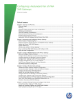
2010
Cautions for laser unit and LED light source unit
Before servicing the machine, be sure to follow the following
instructions to avoid laser beam or LED beam radiation
exposure.
•Do not perform any work other than the work which is
specified in the manual.
•Do not perform the following dangerous works.
• Reflect the light path of the laser unit and LED light source unit
by inserting a mirror or the like in the light path of the laser beam
or LED beam.
• Change the light path of the laser unit and LED light source unit.
• Replace the optical parts while the electricity of the laser unit and
LED light source unit is ON.
• Turn ON the electricity in the removed exposure advance unit.
• Turn ON the electricity in the removed laser unit, LED light
source unit from the machine.
Explanation
• The QSS-32 is IEC Class1 laser unit product, but the laser unit itself is IEC Class4.
• The QSS-32 is IEC Class1M LED light source product, and the LED light source unit
itself is IEC Class1M as well.
Note
• The LED beam is considered to be the laser beam in the general meaning.
• IEC=International Electro technical Commission
3
www.minilablaser.com
32D_2
2020
(Reference) Overview of Laser Safety Classes
Class
Evaluation of danger
Class1
Safe for normal operations, and not hazardous when optical instruments are
used.
Class1M
Wavelength of the laser: 302.5nm to 4,000nm Same as Class 1, but potentially
hazardous when optical instruments are used.
Class2
Wavelength of the laser: 400nm to 700nm Safe for unintended exposure, but
prolonged staring should be avoided. Naked eye is protected by blink reflex.
Class2M
Wavelength of the laser: 400nm to 700nm Same as Class 2, but potentially
hazardous when optical instruments are used.
Class3A
Wavelength of the laser: 302.5nm to 106nm Potentially hazardous when eye is
exposed.
Class3B
Hazardous when eye is exposed, but diffuse reflections are usually safe.
Class4
Diffuse reflection may be hazardous.Hazardous to eye and skin, so protect them.
Fire hazard.
Explanation
• As for the [Class1M], it does not cause physical harm unless you do not see LED beam
directly using lens or optical instruments.
4
www.minilablaser.com
32D_2
2030
Scanner LED light source
LED light source
The LED light source consists of 5 LED which are B, G, R1, R2, and D.
It is different from the halogen lamp. It is suitable for the scanner light
source because it is unnecessary to replace, and it can change the light
intensity of each color by changing the current value.
Light source parts
The light source parts are not consumable parts, so it is unnecessary to
replace them.
Explanation
• There is no additional information.
5
www.minilablaser.com
32D_2
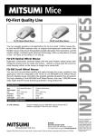
2040
Exposure route of scanner LED light source
CCD
for detecting scratches
CCD
RGB frame detection
Mirror
Scanner zoom lens
Film carrier
Lens
Mirror
Lens
R1, R2, D LED PCB
B, G LED PCB
Explanation
• There is no additional information.
6
www.minilablaser.com
32D_2
2050
Scanner
Image capture method
Optical resolution (Main
scanning)
Input one line image with line CCD.
Scan pitch (Sub scanning)
Strip film:Film is moved.
Mount:Carrier is moved.
CCD
Scan RGB each with line CCD (5340 pixels).
Others
Automatic dust and scratch removal for films is
available. (DIGITAL ICE) *1
Sticker for
permission of use*1
Explanation
• DIGITAL ICE is a trademark of Kodak. *1
7
www.minilablaser.com
32D_2
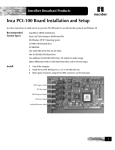
2060
Resolution of the image
• Input resolution (resolution of the image) is different
depending on the film size and paper width each.
Change the resolution of the image by the zoom lens of
scanner.
6774
1565
1037
to
4492
Resolution of the image when scanning 135 film (Unit: pixel)
Explanation
• There is no additional information.
8
www.minilablaser.com
32D_2
2070
Resolution of the image (film size each)
Film size
Minimum
Maximum
135F
1037 x 1565
4492 x 6774
135H
2075 x 1463
4492 x 3167
135P
1265 x 3583
2226 x 6305
240C
1406 x 2110
3043 x 4567
240H
1406 x 2465
3043 x 5335
240P
1448 x 3489
2214 x 5335
110
1109 x 1459
3573 x 4702
6 x 4.5
4824 x 3533
4824 x 3533
6 x 6 (6 x 6V)
4832 x 4760
4832 x 4760
6 x 6H
4760 x 4832
4760 x 4832
6x7
4815 x 5902
4815 x 5902
6x8
4903 x 6610
4903 x 6610
6x9
4903 x 7139
4903 x 7139
Explanation
• In the 120 film, the resolution of the image is constant, but the width [6] of [6 x #] is
slightly different depending on each size on the basis of the 120 size standard.
Therefore, even if you scan it at the same magnification, the resolution of image is to be
the present size as a result, because the film width with image is different.
Note
• In case of wide scanning for 120 and mount, the number of resolution for scanning is as
follows.
6*4.5W
------------ 5078*3859
6*6W (6*6VW)
------------ 5078*5074
6*6HW
------------ 5074*5078
6*7W
------------ 5078*6298
6*8W
------------ 5078*7097
6*9W
------------ 5078*7505
9
www.minilablaser.com
32D_2
2070
Resolution of the image (film size each)
Film size
Minimum
Maximum
135F mount
1120 x 1718
3894 x 5971
135H mount
2241 x 1467
3894 x 2549
240 mount
1474 x 2590
2561 x 4501
Note
• In case of wide scanning for mount, the number of resolution for scanning is as follows.
135F mount W--------Minimum: 1275*1913 Maximum: 4432*6648
135H mount W--------Minimum: 2550*1806 Maximum: 4432*3138
240 mount W----------Minimum: 1774*3209 Maximum: 3082*5575
10
www.minilablaser.com
32D_2
2080
Minimum necessary pixels for paper size each
Size (mm)
82.5
89
102
127
152
Pixel
Size (mm)
Pixel
974
1051
1205
1500
1795
178
203
254
305
457
2102
2398
3000
3602
5398
Note
• Calculating formula
Size (mm) 25.4 x 300 (dpi) (resolution of printer) = Resolution of the image for one side
The above is just the calculated number. Actually the image is scanned a little larger.
11
www.minilablaser.com
32D_2
2090
Scanning
• The zoom value of scanner is decided on the basis
of the largest among the paper sizes, which are
registered in the print channel (C/P/H).
Example)
In the 135F, when setting “89 x 127” and “305 x 457”, the resolution of
image is 4181 x 6305.
The resolution of image for 89 x 127 channel only is 1037 x 1565.
The quality is different depending on the
combination of print channel.
Explanation
• There is no additional information.
12
www.minilablaser.com
32D_2
2100
Print channel and scanning
In case of 3R only
1565
1524
103%
1037
1074
24%
5424
In case of interspersed channel (3R and 12 x
18 inches)
6305
86%
3624
4181
Input data
Output data
Explanation
• There is no additional information.
13
www.minilablaser.com
32D_2
2110
Pre-scanning
Film size
Resolution
Film size
Resolution
135F
259 x 391
6 x 4.5
301 x 220
135H
259 x 182
6x6
302 x 297
135P
138 x 391
6x7
300 x 368
240C
223 x 391
6x8
306 x 413
240H
223 x 391
6x9
306 x 446
240P
223 x 391
135 mount F
342 x 524
110
277 x 364
135 mount H
342 x 223
240 mount
224 x 395
Explanation
• The image data scanned in the Pre-scanning is used for the index prints, label index prints,
index prints of contact print style photos and for monitor display.
14
www.minilablaser.com
32D_2
2120
DIGITAL ICE Technology
CCD for detecting
scratches
CCD
RGB frame
detection
Mirror
Corrected image
The data with
scratch
RGB
scanning data
Lens
Original
image
Film
Explanation
• The technology to make the images without scratch, dust, etc. In addition to the CCD
which takes the color information of RGB, the another CCD is added. It detects the dust,
scratch, etc on the film. This corrects the scanned image information.
15
www.minilablaser.com
32D_2
2130
Function to remove the scratch and dust on the film
Comparison table with the conventional models
Scratch and dust
removal function
on the film
Scratch removal function on the base side of the film (DIGITAL ICE:standard)
Scratch removal function on the base side and the emulsion side of the film
(Digital Masking:option)
The conditions for functioning the scratch and dust removal function on the film
DIGITAL ICE:Standard
Digital Masking :Option
PCB
D-ICE PCB (standard)
D-ICE control PCB (standard)
D-ICE PCB (standard)
D-ICE control PCB (standard)
Scratch mend PCB 1 x 2 (option)
Scratch mend PCB 2 (option)
Data change over PCB (option)
DIMM (option)
Installing the
software
Unnecessary
Unnecessary
Registration in the
mode
Place a check mark for [DIGITAL
ICE Correction] in [Operator
Selections].
Place a check mark for [Digital
Masking Unit] in [Operator
Selections].
You can set the [Digital Masking Unit]
ON or OFF in the [Operator Selection].
Important
• As for the scratch and dust removal function on the film, in addition to the conventional
DIGITAL ICE, the Digital Masking (the scratch removal function on the base side and
the emulsion side of the film) which is developed by the NKC is added.
• When explaining about the scratch removal function on the base side and the emulsion
side of the film, please call it Digital Masking which is developed by the NKC.
Note
• The Digital Masking Unit (option) consists of Scratch mend PCB 1 x 2, Scratch mend
PCB 2, Data change over PCB, and DIMM.
• If the Digital Masking Unit is attached, a check mark is placed for the option registration
automatically.
16
www.minilablaser.com
32D_2
2140
Scratches and dust which can be corrected
(e.g.)In case of color negative
Scanner side
Scratches and dust which can or cannot be corrected
DIGITAL ICE: Standard
x
x
-
-
-
-
-
x
Digital Masking: Option
x
x
x
x
-
-
-
x
Dust
Base layer
Red photosensitive
Green photosensitive
Blue photosensitive
Protective layer
Dust
Negative
x: possible
LED light source side
Explanation
• The DIGITAL ICE deletes the dust or scratch, which is stuck to the film surface,
automatically.
• When the Digital Masking unit is installed, it is possible to delete the scratches such as
the scratch reaches photosensitive from the protective coat.
• However, it is impossible to delete the deep scratches such as the scratch reaches the red
photosensitive from the protective coat or the scratch reaches the red photosensitive from
the base layer.
• The DIGITAL ICE does not function normally when a lot of silver is included in the part
where the image is created, like in case of monochrome films and desilvering.
• In the KodakChrome films, the effect of DIGITAL ICE is weak to the high density or
low density of a film, and the scanned image will deteriorate.
Turn OFF the function of DIGITAL ICE before printing.
You can set the function of DIGITAL ICE ON or OFF in the “Operator Selection”.
(However, in case of monochrome film, the DIGITAL ICE is turned OFF automatically.)
Note
• The D light cannot detect the oil. Therefore, fingerprints cannot be deleted because they
are made from oil.
• The “blurring caused by the roller pressure” cannot be corrected.
17
www.minilablaser.com
32D_2
2150
Colorimeter
Changes from the conventional machines
• It is possible to set the 305 size paper to the colorimeter
without cutting it.
• The calibration plate is built into the colorimeter.
• When measuring test prints or calibration plate, they are
touched to the colorimeter by using the pressure change
solenoid. By doing so, the precision of color measuring is
improved because they are less influenced by outside light.
Important
• It is very important to clean the calibration plate because the gradation from white to
black changes by the dirt on the plate.
• Clean the calibration plate with a neutral detergent and water.
The Maintenance Manual [Cleaning the Calibration plate]
18
www.minilablaser.com
32D_2
2160
Paper sizes and transportation
Paper transportation
As for the paper advance unit 2, there are 4 kinds of lane select
operation, and the conditions are as follows.
Condition of paper advance
Paper width:152.0mm or less
Paper advance length:178.0mm or less
Service Manual
55500
Paper width: 152.0 mm or less
Paper advance length: 178.1mm to 305.0mm
Paper width: 152.0 mm or less
Paper advance length: 305.1 mm or more
Paper width: 165.0 mm or more
* Refer to the Service Manual Chapter 5 for details.
Explanation
• There is no additional information.
19
www.minilablaser.com
32D_2
2170
Laser Engine
Laser:
Light Amplification by Stimulated Emission of Radiation
The exposure method by Visible Radiation is employed like the
conventional machines.
Note
• Merit
(1) It is possible to reduce the power consumption in the printer.
(2) The uniformity calibration is unnecessary.
(3) The laser is not affected by the magnetism.
20
www.minilablaser.com
32D_2
2180
Printer Exposure Engine
Exposure
method
Output
gradation
Maximum
exposure width
Print resolution
Line exposure method by the Laser engine
4096 gradation
315 mm (12.4-inch)
300 dpi (Main Scanning) x 600 dpi (Sub
Scanning)
Exposure speed 58.42 mm/sec
Light source
B laser, G laser, R laser
Explanation
• The exposure speed by the laser engine is kept at a constant speed and it does not change.
• The maximum exposure width is the value including the hem for adjusting the exposure
center.The maximum exposure width to the paper is 305mm.
21
www.minilablaser.com
32D_2
2190
Structure of Laser Unit
Mirror
AOM
Paper
Fθ lens
Synchronous Sensor
Polygon mirror
Explanation
• The prism is disappeared.
22
www.minilablaser.com
32D_2
2200
Explanation of laser unit
Laser
Visible Radiation Laser for R, G, B each
AOM
Acousto-Optic Modulator
Adjusts the strength and weakness of laser light.
Mirror
Changes the direction of laser light.
Polygon mirror
Rotates in a certain speed and scans in the Optical resolution (Main line).
Fθ lens
Changes the angle of laser light according to the angle of incoming light,
and maintains the constant speed.
Synchronous Sensor
Detects the scanning timing of R, G, B
Explanation
• There is no additional information.
23
www.minilablaser.com
32D_2
2210
Structure of Laser Unit (AOM)
•
•
AOM controls the strength of laser light.
The diffracted light of first order is used for exposure.
Diffracted light of
first order
Laser
AOM
100 %
20 %
Exposure
80 %
0-th order light
The direct light is called 0-th order light.
Explanation
• When the voltage is not turned ON to AOM, the incoming laser beam passes through as it
is.(0-th order light)
• When turning ON the high frequency voltage, the ultrasonic waves occurs, and the
diffracted light which is separated from 0-th order light occurs.(Diffracted light of first
order)
• Change the rate of 0-th order light and the diffracted light of first order by changing the
high frequency voltage on AOM, and control the strength of light (diffracted light of first
order) to be used for exposure.
24
www.minilablaser.com
32D_2
2220
Structure of Laser Unit (Fθ lens)
Polygon mirror
Fθ lens
• The Fθ lens corrects the dispersion of
linear velocity caused by the angle of
incoming beam.
θθ
Paper
A
A
B
Exposure center
Explanation
• The travel (distance) on the paper is different between “the light outputted from the
exposure center at the angle θ” and “further output light at the angle θ” The travel
(distance) on the paper is different between “the light outputted from the exposure center
at the angle light at the angle θ and “further output light at the angle θ.(As shown in the
illustration, length A, B).
• The Fθ lens changes the angle of diffracted light according to the angle of incoming
beam, and corrects the difference of travel (distance) on the paper.
25
www.minilablaser.com
32D_2
2230
Laser Exposure
Image data
Paper advance direction
Exposure position
Exposure image
Polygon mirror
Explanation
• Resolution
Optical resolution (Main or the CCD line): 300 dpi
Scan pitch (Sub Scanning): 600 dpi
• Reason why the sub scanning is exposed to overlap.
(1) To get the soft image without the scanning unevenness (density difference of 1
scanning line).
(2) Not to occur the open caused by the time-lag between the advance and exposure.
(3) Not to show the unevenness of color when the time-lag of exposure occurs.
26
www.minilablaser.com
32D_3
Chapter 3
Operation
Explanation
• There is no additional information.
1
www.minilablaser.com
32D_3
3000
The point of this chapter
Key points
• Study the operations
Printing operations, Start up checks, Close down checks, ON/OFF procedure of power
supply
Status display of LED, CD-Viewer, CVP (Correction Value Print), Index prints
Upon completion of the lesson, you will be able to:
•
•
•
•
•
•
•
•
Explain each printing operation to users.
Explain the image storing to media to users.
Explain printing operations in the EDIT mode to users.
Explain the input from Flatbed scanner to users.
Explain the start up checks and close down checks.
Explain ON/OFF procedure of power supply to users.
Explain the status display of LED, details of CVP and index prints.
Understand about the CD-Viewer.
How to proceed the training
Carry out the practical training, or explain the items using the sample prints.
2
www.minilablaser.com
32D_3
3010
Setup during the start-up checks Daily setup
Execute once a day for each paper type to be used.
Correct the temporary aging of exposure engine, light
source and processing solution.
Make a 22-step test print.
Explanation
• The laser engine causes the temporary aging by the fall of maximum output, change of
output wavelength and dirt of optical parts.
Note
• The weekly setup and the monthly setup are unnecessary from the QSS-32.
3
www.minilablaser.com
32D_3
3020
Daily setup flow
Make a test print. (22-step setup print)
When the light source
upgrading (auto) is
not carried out
correctly during the
program timer,
Colorimeter calibration (auto)
When the light source
upgrading (auto) is
carried out correctly
during the program
timer
Light source upgrading
Sensor LED Light Intensity Adjustment
Measure a test print
Registration
Explanation
• After exposing the test print, the calorimeter calibration will be executed automatically.
• The light source update is executed automatically for the carrier to be set during the
program timer.
e.g.) When 240 lane is set: 240 light source update is executed.
When 120 AFC is set, 120 light source update is executed.
• When the light source update is not completed correctly during the program timer, it is
executed again automatically for the carrier to be set during the daily setup.
Note
• As for the other carriers except the one to be set during the program timer, update the light
source when replacing the carrier or switching the lane.
However, update the light source when 24 hours have passed from the last update.
4
www.minilablaser.com
32D_3
3021
Daily setup flow (Stand alone scanner)
Scanner Change of Light
Registration
Sensor LED Light Intensity Adjustment
Explanation
• As for the stand alone scanner, there is no program timer function, so make sure to
execute the light source upgrading during the daily setup.
Refer to the S-900SA/S-1700SA Maintenance Manual [Daily Setup].
5
www.minilablaser.com
32D_3
3030
Explanation of operations
• Explain with the actual machine.
Explanation
• As for AMC, up to 40 mounts can be set.
• Use the dummy mounts of AMC when switching the order.
• AMC is available for PJP.
• Components of AMC
Main body
Insertion stocker
Ejection stocker
Dummy mount (for switching the orders) Quantity: 5
Single adapter
Packing unit
• When the media output destination is MO, FD, DVD, ZIP, or CD-R/RW, it is possible to
specify [number of media] and [number of label index prints].However, make sure that
[Additional Writing] is set to [No] on the [Option Registration] display. When
[Additional Writing] is set to [Yes], it is impossible to set [Label Counts].
[Number of media]:Can be set on the message [No.1527 Write the Data. Set the media].
[Number of label index prints]:Can be set on the Order display.
• The following contents can be specified on the [Print operation] tab of Operator selection
screen.
[Color selection of print blank of positive]:Possible to select White or Black for the
unexposed part.
[Paper remaining count display]:Possible to select [Count distinct paper magazine A and
B] or [Count mix paper magazine A and B].
6
www.minilablaser.com
32D_3
3040
Explanation of modes
•
Explain the modes, checking the actual machine.
Explanation
•
Paper temperature change correction
R light changes by the temperature change of inside of laser unit and surrounded
temperature. The color development of paper may be different.
In this case, input the correction value in the “Paper temperature change correction”.
Corrections:Refer to the Operator's Manual -Additional Operations & Setup Manual [Correcting the paper coloration due to the temperature variations [Paper Temperature
Correction]].
•
CCD noise suppression strength: Correction which is effective only for Under/Over
part of films.Noise is likely to occur in parts where there is not much light, so the
correction is done only for the part.
Note
•
As for the setup and mechanical adjustment, carry out the practical training, so skip the
explanation here.
7
www.minilablaser.com
32D_3
3041
Explanation of modes (Stand alone scanner)
•
The modes which are related to printer and paper
processor are not displayed.Or, if they are displayed, they
are not available.
Refer to the Service Manual[Mode structure chart [Stand
alone scanner]] in [3. Mode]
•
[1 Frame Magnification display] is not available.
•
[Monitor Setup] is not available.
•
Explain the modes, checking the actual machine.
Explanation
•
There is no additional information.
8
www.minilablaser.com
32D_3
3042
Color Management (Stand alone scanner)
Menu
Extension
• It is possible to switch the [Color Space of Output Media Image] in the QSS.
Setup
• [Standard]: The standard color space of QSS series.(default)
• [sRGB]: The general sRGB color space
Master Data
• Select this when using the image which is saved with QSS series in the
sRGB environment.
Color management
Explanation
• When changed the setting of [Color Space of Output Media Image], it takes about 3 minutes to
register it.
Because a profile will be made when changing the [Color Space].
9
www.minilablaser.com
32D_3
3050
Shortcut key
•
Explain, checking an actual machine.
Shortcut key
PASS (F11) REP (F2)
(
Mode
Setup
Y (F5)
Maintenance
M (F6)
Version check
C (F7)
History of movement
D (F8)
Machine specification
-1 (F9)
Operator selection
N (F4)
List of Print channel
+1 (F10)
Option registration
) : Shortcut key in the Full keyboard
Explanation
• The above Shortcut key is used very often.
10
www.minilablaser.com
32D_3
3060
Black balance adjustment
[Black balance adjustment] is the mode to adjust the blur around Black letter (the
defective of color balance) on the print.
Blur around the Black letter
Explanation
• The [Black Balance Adjustment] is included in the initial setup and the Setup of the Paper
Specification Registration/Setup.
Also, there are [Black Balance Adjustment] and [Black Balance Adjustment (Manual)] in
the [Functions] of the Paper Specification Registration/Setup.
• Refer to the Operator's Manual -Additional Operations & Setup Manual - [Adjusting the
blur of letters (color balance) [Black Balance Adjustment]].
• Refer to the Service Manual [32510].
Note
• This is not effective for the dark part of 22-step print, etc.
11
www.minilablaser.com
32D_3
3070
What is the compact archive unit?
• Image storing to compact archive unit
• Print from compact archive unit
(Image storing to media)
Print
Films and the storage media
Films and the
storage media
Compact Archive Unit
Compact Archive Unit
Storage
media
• Image data: Scanning data which the scratch has been removed, and the data with the
magnification when scanning
• Correction data: Stored in the HDD for CAU which is same as the image data
Explanation
• The compact archive unit is an option to save the image data or storage media of scanned
film to the HDD for CAU.Also, the image data which is stored to the HDD for CAU can
be printed and written to the each storage media.
• In the compact archive unit, the image data is stored with ‘the color correction data, etc.’
memorized. Therefore, it is no need to scan the negative again in case of reprint, etc.
• The image data which is stored to the HDD for CAU is not the universal data but the raw
data of scanner.This cannot be used as the image data except when processing with the
QSS.
• The correction data is stored in the HDD for CAU.
Image correction data: Key correction data, 1 Frame Magnification correction data, DSA
correction data, Number of prints
Inner data: Negative size/Types, Frame No., Information, Magnetic data information (240
only)
• The stored image data and correction data cannot be backed up.
It is impossible to make a back up in the “Backup the data (Close down checks mode)”
and “Reading and Writing the data (Maintenance mode)”.
Note
• [CAU] is the abbreviation of Compact Archive Unit.
12
www.minilablaser.com
32D_3
3080
Specification of compact archive unit 1
• Available image: Only the image scanned from film
• Storage capacity:
Film (negative)
Storage capacity Condition
(80GB x 1 HDDs)
135F-24EX
approx. 160
films
HC of 3R only (89 x 127mm)
1037 x 1565 pixels/1 frame
• Storage speed: It is different from the CAU of the QSS-30. It processes with the
HDD of the QSS, so the processing capacity decrease a little when saving the image
data from the film to CAU.
• Reading speed: Same with the normal scanning speed
• Available print mode: Normal Print/package/Album (Edit is out of guarantee)
AUTO/PJP/PPI (4/6 frames)
Explanation
• There is no additional information.
13
www.minilablaser.com
32D_3
3081
Specification of compact archive unit 2
• Prohibition of automatic deletion
When the capacity of HDD is full, the data is deleted automatically from the oldest
data.
Possible to store ‘the data you don’t want to delete’ if “Hold on Save Mode” is
selected in the “Archive mode”.
• Reading the image data
Possible to read the image data by selecting the archive code from the list of stored
image.
Possible to read by the number input of archive code.
Possible to print by selecting plural orders in bulk.
• Magnification
The rate of enlargement/reduction, as compared to
the time that the image was archived.
• Index prints
• CVP
Explanation
• The specific No. for order each (archive code) is imprinted on the index print and back
print (CVP). Reprint is possible without negative by checking the archive code.
Index print: The archive code is displayed on the upper part of print.
Back print (CVP): When storing the image to compact archive, the printing of CVP is
different.(Explain the details in the “Details of back print”.)(Explain the details in the
“Details of back print”.)
• Magnification
If you make a print with bigger size than the stored one in the Archive, the magnification
becomes bigger and the quality may become lower.
• When making a print from the Archive, the image data stored in the Archive is not
overwritten.
However, the correction data only is overwritten.
[Example]
Print size
Magnification (%) Archive
Correction
1st time
+1D
89 x 127
2nd time
+1D, +1Y
127 x 178
114
3rd time
+1D, +1Y
89 x 127
100
100
14
www.minilablaser.com
32D_3
3090
CD Viewer (Simple Viewer Software)
In the QSS-27 or later, the Viewer
Software is standard.
Up to 5 orders can be displayed.
If you install the CD viewer utility
software, you can set the
customer’s shop information and
logo data on the viewer software.
Explanation
[Explanation of Main function]
• Select the image data of film.
The images are put in order for each film(Maximum: 5 orders)
• Set the image size for display.
You can select the display from 3 patterns.
Big size/ Middle size/ Small size
• Slide show
You can select various slide display patterns.
• Store the image to each media.
You can specify the image form and store it to the media.
• Mail attachment
You can attach your favorite photos in the mail automatically.
• Pint order form
You can make a print order sheet. This enables to make a print from the images in the
CD.
• Set the display screen
You can select the image quality for image display.
15
www.minilablaser.com
32D_3
3100
CD Viewer (Deluxe viewer software)
Up to 5 orders can be
displayed.
If you install the CD viewer
utility software, you can set
the customer’s shop
information and logo data on
the viewer software.
•
The deluxe viewer software is not sold as the software.So, you can not write the deluxe viewer software from a
machine to generic CD-R and R/W.
The QSS CD is supplied from NORITSU.
The Deluxe Viewer software is contained in the QSS CD in advance.
•
Explanation
[Explanation of function]
• Image display
1 frame, 3 frames, 6 frames, 15 frames, Index display
Slide show
Store in my photo
• Corrections
Red-eye Correction, Brightness, Noise Removal, Contrast,
Sharpness, Unsharp, Saturation
• Special effects
Puzzle, Solarize, Monotone, Sepia, Mosaic, Blur,
Pointillize, Emboss
• *
**
• Make the post cards.
16
www.minilablaser.com
32D_3
3110
QSS CD
• The QSS CD is supplied from NORITSU as an option.
The Deluxe Viewer software is contained in the QSS CD in advance.
<Kinds>
Name
Contents
Record
Label
QSS CD (TYPE A)
*
*
*
QSS CD (TYPE B)
*
*
*
QSS CD (TYPE A)
*
Deluxe
Viewer
QSS CD
QSS CD (TYPE B)
*
Deluxe
Viewer
Printable
Source of
supply
Attachment
NORITSU
Nonwoven fabric
Manual
•Each CD has part number.
•The attachment is stored in the CD-R case.
Explanation
• The deluxe viewer software is not sold as the software.So, you cannot write the deluxe
viewer software from a machine to CD-R and R/W.
17
www.minilablaser.com
32D_3
3120
CD-R Engine
•
In the QSS-27 or later, the CD-R Engine is the software to write the
image to QSS-CD that contains the Deluxe viewer software.
•
In the QSS-27 or later, this software is required to see the Simple viewer
software in the Mac.
Noritsu CD-R Engine (Windows/Mac)
Software version which is compatible or will be compatible with Noritsu CDR Engine (Windows/Mac)
QSS-2701D
Not supported
QSS-2801D
Ver.G001 or later
QSS-2901D
Ver.E001 or later
QSS-3001D
Ver.E001 or later
QSS-3101D
Ver.C001 or later
QSS-32
The limited shipment Ver. or later
Explanation
• As for the QSS-32, it is unnecessary to install the Mac CD because the CD-R Engine
(Windows/Mac) is not available.
• As for the QSS-32, Noritsu CD-R Engine (Windows/Mac) only is available.
• Refer to the PC Manual [Procedure for installing the CD-R Engine] for the Noritsu CD-R
Engine (Windows/Mac) installation.
18
www.minilablaser.com
32D_3
3130
CD Viewer Utilities
This is the software to edit the
display contents of CD Viewer.
You can set the customer’s shop
information and logo data.
Simple viewer software and Deluxe
viewer software are common.
Install the software from “CD_Viewer_Utility” folder
in the system program CD of each machine.
Explanation
• There is no additional information.
19
www.minilablaser.com
32D_3
3140
Setting of the CD-R/RW writing
• When writing to the QSS CD
Set in the “Image Save” of “Operator Selections”.
Mark the check box for “Switch for Deluxe Viewer”.
Set the “Shop data” folder.
• When writing the generic CD-R/RW
Set in the “Image Save” of “Operator Selections”.
Remove the check box “Switch for Deluxe Viewer”.
Mark the check box “Writing Viewer Software”.
Set the “viewer software” folder.
(The simple viewer software which is standard of this product is set in the initial setting.)
Explanation
• If you install “CD-R Engine (Windows/Mac) software, you can set the “Switch for
Deluxe Viewer”.
• As for the registration of “shop data”, refer to the “CD Viewer Utility software”
Operator’s Manual.
20
www.minilablaser.com
32D_3
3150
ON/OFF procedure of power supply
The PC has begun the
shutting down.
Close down
checks
2 hours and
a half
200V power supply
OFF
The time to start
temperature adjustment
The PC has been
started up.
5
minutes
Manual sorter switch
OFF
ON
The PC has already
been shutting down.
The maximum waiting time to
complete the disk defragmentation: 2
hours and a half
Blinking
OFF
The PC has begun
starting up.
The PC is being processed.
Explanation
• Refer to the Getting Started [Closing down the machine with the program timer],
[Closing down the machine without using the program timer] for details of the normal
shutdown movement.
• Refer to the Getting Started [Stating the machine when the temperature adjustment has
been done], [Starting the machine when nothing is shown on the display] for details of the
normal start up movement (When the program timer is activated.).
• Refer to the Troubleshooting Manual [Turning off the power supply for troubleshooting],
[Turning on the power supply after troubleshooting] for details of when turning the
breaker OFF in the case of troubleshooting, etc.
• Refer to the Troubleshooting Manual [Restarting the machine when it freezes up] for
details of how to turn OFF the breaker when the PC has been freezing.
• Refer to the Troubleshooting Manual [Turning off the power supply in an emergency] for
details of how to turn OFF the breaker in an emergency.
• Refer to the Service Manual [68550] for details of when the PC does not start up (error).
21
www.minilablaser.com
32D_3
3151
ON/OFF procedure of power supply (Stand alone scanner)
Power OFF
The PC has begun the
shutting down.
Close down
checks
2 hours and
a half
The breaker of the
machine is OFF
5
minutes
The breaker of the
machine is ON
The PC has
been started up.
5
minutes
The PC has already
been shutting down.
The maximum waiting time to
complete the disk defragmentation:2
hours and a half
Power ON
The PC has begun
starting up.
The PC is being processed.
Explanation
• Refer to the Getting Started of S-900SA/S-1700SA [Starting up the machine], [Closing
down the machine] for details of the normal shutdown movement.
• Refer to the Troubleshooting Manual of S-900SA/S-1700SA [Turning off the power
supply for troubleshooting], [Turning on the power supply after troubleshooting] for
details of when turning the breaker OFF in the case of troubleshooting, etc.
• Refer to the Troubleshooting Manual of S-900SA/S-1700SA [Restarting the machine
when it freezes up] for details of how to turn OFF the breaker when the PC has been
freezing.
• Refer to the Troubleshooting Manual of S-900SA/S-1700SA [Turning off the power
supply in an emergency] for details of how to turn OFF the breaker in an emergency.
22
www.minilablaser.com
32D_3
3320
Status display of the processor
Status lamp of
processor
Condition of display
Lighting Green
The temperature adjustment is completed.
Blinking Green
During the Program timer
Note
Slow blinking
(From “After the close down checks is completed.” to
“The time to start the temperature adjustment”)
Blinking Red
When it is impossible to activate the temperature
adjustment (When the error occurs or the interlock
switch is activated.)
Dark
The processor section does not start-up. During the
temperature adjustment
Sorter switch
Condition of display
Dark
The PC is being functioned.
Blinking
While the PC is being started-up.
Lighting
During the program timer or the power supply of PC
is turned OFF.
Slow blinking
Note
Slow blinking
Explanation
• There is no additional information.
23
www.minilablaser.com
32D_3
3330
Status display of the scanner
Ready lamp
Condition of display
Lighting Green
Films can be processed. (You can insert a film.)
Blinking Green
Film is being processed. (You cannot inset a film).
Blinking Red
Films cannot be processed.(You cannot process a film.)
• The error occurs. (You cannot process a film.)
Dark Films cannot be processed.(You cannot process a film.)
• When the “Film” is not selected for “Image input” in the print channel setting.
• During the start-up checks and close-down checks
• During the Program timer
• When the message “Insert a film.” does not appear on the adjustment mode.
• During the initial movement
Explanation
• There is no additional information.
24
www.minilablaser.com
29D_3
3340
Details of the back print
• When making prints from except the IX240 film
• When making prints from the IX240 film
• Back print of the print from the storage media
• Back print of the combined print
• Back print when using the CAU
Explain, checking the Operator's Manual - Basic Operations [Checking back prints].
Explanation
• There is no additional information.
25
www.minilablaser.com
32D_3
3370
Types of index prints
Normal index prints
Make normal index prints.
The data for displaying on the PJP mode is used.
Label Index
Index print for the media case size of storage media
The digital camera media such as the Smart Media,
Compact Flash, etc are not available.
Contact Print Style
Photos
Make Contact Print Style Photos.
Explanation
• The pre-scanning data is used for the output of index print.
• The pre-scan data is enlarged and prints are made.
• Index logo data size
When you make the original logo data;
Image size: 164 x 494 pixels
Saving format: bitmap (bmp)
Note
• When processing the contact print, the negatives and positives of 120/110 are printed in
the same format as the 135F.
26
www.minilablaser.com
32D_3
3380
Index print sizes (135/240 films)
Format Paper size
(mm)
28-frame
40-frame
15-frame
25-frame
3HS
82.5 x 158
-
x
-
-
-
3R
89 x 127
x
x
x
x
x
3HD
89 x 158
x
x
x
x
x
3W
89 x 178
-
-
x
x
x
3WS
89 x 178
x
x
x
x
x
4R
102 x 152
x
x
x
x
x
4HD
102 x 178
x
x
x
x
x
-: Not available
5R
127 x 178
x
x
x
x
x
*1: Printing is possible, but a
whole of the image does
not appear on the print.
6R
152 x 203
x
x
x
x
x
6HD
152 x 254
x
x
x
x
x
6W
152 x 305
x
x
x
x
x
8RS
203 x 254
x
x
x
x
x
8R
203 x 305
x
x
x
x
x
8HD
203 x 356
x
x
x
x
x
CD_40
120 x 120
-
x
-
-
*1
CD_40A
89 x 120
-
x
-
-
*1
CD_40B
102 x 120
-
x
-
-
*1
3WL
89 x 254
x
x
x
x
x
• Normal index
prints 135/240
films
x: Available
240 films
135 films
40-frame
Explanation
• There are 3 types of Index print sizes for CD.
• 135 film restrictions
When selecting 3HS, CD_40/40A/40B, it is printed in 40-frame format.
• 240 film restrictions
When selecting CD_40/40A/40B, it is printed in 40-frame format.
But, a whole of the image does not appear on the print because the aspect ratio is not
constant.
Note
• 110 film restrictions
Same with the restrictions of 135 films. But, a whole of the image does not appear on the
print because it is printed in 135 format.
• Media
Same with the restrictions of 135 films. But, a whole of the image does not appear on the
print because the aspect ratio is not constant.
27
www.minilablaser.com
32D_3
3390
Index print sizes (120 films)
Format
Index
Paper size
(mm)
12-frame
3HS
82.5 x 158
*1
*1
3R
89 x 127
*1
*1
3HD
89 x 158
*1
*1
3W
89 x 178
-
-
-: Not available
3WS
89 x 178
*1
*1
*1: Printing is possible, but a whole of the
image does not appear on the print.
4R
102 x 152
*2
*2
4HD
102 x 178
*1
*1
Normal index prints
120 films
*2: Printing is possible, but the logo data is not
printed.
6*4.5, 6*6
:18-frame format
6*7, 6*8, 6*9 : 12-frame format
18-frame
5R
127 x 178
*1
*1
6R
152 x 203
*1
*1
6HD
152 x 254
*1
*1
6W
152 x 305
*1
*1
8RS
203 x 254
*1
*1
8R
203 x 305
*2
*2
*1
8HD
203 x 356
*1
CD_40
120 x 120
*1
*1
CD_40A
89 x 120
*1
*1
CD_40B
102 x 120
*1
*1
3WL
89 x 254
*1
*1
Explanation
• There are 3 types of Index print sizes for CD.
• 120 film restrictions
• When selecting [4R], [8R], the logo data is not printed.
• When selecting 4R, 8R, the number of frames to be printed is different.
Film size 6 x 4.5, 6 x 6: 18-frame format
Film size 6 x 7, 6 x 8, 6 x 9: 12-frame format
• When selecting the size except [4R] and [8R], it will be printed in 28-frame and 40frame format and a whole of the image does not appear on the print.
• When selecting CD_40/40A/40B, it is printed in 40-frame format, and a whole of
the image does not appear on the print.
28
www.minilablaser.com
32D_3
3400
Background color for index prints
• The color can be selected as a background color of an index print.
1. Gray
5. Orange
2. White
6. Green
3. Pink
7. Light blue
4. Yellow
8. Purple
Black is for the Contact print style photos.
9. Black
Explanation
• Select the background color for [135/120/110/Media], [IX240] and [Contact print style
photos] each.
29
www.minilablaser.com
32D_3
3410
Label index prints
Types of media
Size
FD
MO
ZIP
CD/DVD/HD
89 x 114
89 x 117
97 x 120
120 x 120 (12 cm
CD’s)
80 x 85
(8 cm CD’s)
89 x 120*
102 x 120*
Format (number of
frames)
Index logo
Note
6, 20, 35
6, 20, 35
6, 20, 35
40
Used
Used
Used
Used
The number of
frames are
switched
automatically.
The number of
frames are
switched
automatically.
The number of
frames are
switched
automatically.
The number of
frames are
fixed.
*:
[89 x 120] or [102 x 120] is selected automatically.
When the magazine with 102 paper width is not set: [89 x 120]
When the magazine with 89 paper width is not set: [102 x 120]
Explanation
• The label index is made automatically at the same time of storing the images to media.
However, you can set “None” for the label index print.
• When the paper width is larger than the print size, the image is centered, so the
unexposed part appears on both sides of the print.
• The size of Label index prints for CD are switched automatically according to [CD type]
setting which is selected in [Option registration] → [Media] → [CD-ROM (CD-R/RW)].
And, the size of Label index prints for Business card CD’s and other uniquely shaped
CD’s are also the same.
30
www.minilablaser.com
32D_3
3420
Index print sizes for Contact Print Style Photos
Paper sizes for 6-frame
Name
CP6_1
CP6_2
CP6_3
CP6_4
CP6_5
CP6_6
CP6_7
Paper width
(mm)
82.5 or
more
82.5 or
more
120 or
more
165 or
more
203 or
more
240 or
more
240 or
more
228.6
228.6
228.6
228.6
228.6
228.6
263
Paper advance
length (mm)
Paper sizes for 4-frame
Name
CP4_1
CP4_2
CP4_3
CP4_4
CP4_5
CP4_6
CP4_7
CP4_8
Paper width
(mm)
82.5 or
more
82.5 or
more
120 or
more
152 or
more
152 or
more
152 or
more
152 or
more
152 or
more
152
152
152
152
191
227
263
300
Name
CP4_9
CP4_10
CP4_11
Paper width
(mm)
152 or
more
152 or
more
152 or
more
336
372
407
Paper advance
length (mm)
Paper advance
length (mm)
Paper advance length: Size when printing with
minimum paper width
135/110/120 only are available.
Explanation
• The frame (format) of contact print style photos can be selected in the Index setting of
print channel.
• When making contact print style photos with 120/110 films, the print is made with 135F
format.
• It is possible to read the frame data of contact print style photos.(Bitmap, 3632 x 549
pixels)
Note
• CP of CP4_1 stands for Contact Print Style Photos.
31
www.minilablaser.com
32D_3
3430
Index prints for Contact Print Style Photos
Index prints for Contact Print Style Photos
CP4_1
CP6_1
CP4_8
CP6_3
Explanation
• As for the Contact Print Style Photos, the following types are available for each machine.
Contact Print Style Photos with 4-frame:
QSS-28: (1-line to 8-line)
QSS-30: (1-line to 11-line)
QSS-30: (1-line to 9-line)
Contact Print Style Photos with 6-frame:
QSS-28: (1-line to 3-line)
QSS-30: (1-line to 7-line)
QSS-30: (1-line to 5-line)
• The Contact Print Style Photos are not available for IX240.
• In the Contact Print Style Photos, the printing direction (horizontal or vertical) is changed,
depending on the paper width.
32
www.minilablaser.com
32D_3
3440
Practical training
• Carry out the close down checks.
• How to exit from the close down checks mode
• How to finish the application
• When executing the close down checks, make sure to
finish after setting to the lane of the 135/240AFC-II to
the 135 lane.
Explanation
• The disk defragmentation is completed in approx. 20 to 150 minutes.
• If you execute the disk defragmentation regularly, the required time to defrag can be
shortened.
33
www.minilablaser.com
32D_3
3450
Front print from Media
Digital camera media
Imprinting specification
of DPOF
YES
YES
(DTM data is included
in the image.)
(Setting including DTM)
Imprinting the
data of exposure
NO
NO
YES
Imprinting
specification of EXIF
(Not print)
NO
Date 1 exists in
Exif.
YES
NO
Date 2 exists in
Exif.
Without the imprinting of date
YES
Imprinting the
latest saving date
NO
Explanation
• Refer to the Operator’s Manual –Additional operations- for the Front print setting.
• Even when the front print setting is ON, the front print is not imprinted if there is no
applicable DPOF data.However, date of Exif data for the image is imprinted if [Print] is
selected for Exif imprinting setting.
• [DTM] : {DATA TIME}, data of date of exposure
• Date 1 (Exif) : {Data Time Original}, data of date of exposure
• Date 2 (Exif) : {Data Time Digitized}, date of edit by Photoshop, etc.
34
www.minilablaser.com
32D_4
Chapter 4
Installation
Explanation
• There is no additional information.
1
www.minilablaser.com
32D_4
4000
The point of this chapter
Key points
• Study the installation of the machine.
Width for carrying a machine, Space for installation, Packing items, PC peripherals,
Allocation of drives, Setting the language specification
Upon completion of the lesson, you will be able to:
• Understand the width for carrying a machine and space for installation and judge whether it
is possible to bring a machine to a customer’s shop.
• Understand the packing parts and judge whether all parts are prepared in the installation.
• Understand the angle brackets to be removed in the installation and the parts to be attached,
and work smoothly.
• Execute the following things.
- Setting of language specifications, Each setting after attaching each drive, Allocation of
drives -
How to proceed the training
• The trainer will provide an oral explanation of the cautions, referring to “Installation
Manual” and a machine.
• Carry out the mechanical adjustment or installation of options in the other chapter.
You do not carry out the practical training here.
2
www.minilablaser.com
32D_4
4010
The width to carry a machine
Unit : mm
System name
Minimum height
Minimum width
CS-1 (standard PC)
1065
750
CS-1 (High spec
PC)
1225
LP-1700
1222
770
PP-1213/17
1375
770
Explanation
• As for the S-900SA/S-1700SA, CS-1 (standard PC) only is available.
3
www.minilablaser.com
32D_4
4020
Packing items (S-2)
Packing parts
S-2 main body
Film cleaner mount
Film cleaner kit (option)
Packing items (135/240AFC-II)
Packing parts
135/240AFC-II main body
Cleaning leaders
IX240 film adaptor
135 film loading guide
Curl film setting roller
Explanation
• There is no additional information.
4
www.minilablaser.com
32D_4
4030
Packing items (CS-1)
Packing parts
CS-1 main body
Monitor
Film receiving box (option)
Mouse pad
Air filters
Monitor hood (option)
Capacity booster A
Calibration plate
Explanation
• The operation keyboard, keyboard for inputting the letters, mouse are shipped together
with a machine main body.
• The capacity booster A may not be included in the packing parts depending on the model.
• Refer to the Training Material [1020 Name of the system and the processing capacity of
the QSS-32] for details.
• As for the S-900SA/S-1700SA, the connector for connecting to the power supply is
attached.
5
www.minilablaser.com
32D_4
4040
Packing items (LP-1700)
Packing parts
LP-1700 main body
Magazine lock lever
Ribbon cassette (option)
Pressure guide
Sample print
Standard accessories
Explanation
• The Magazine is shipped with the machine main body.
6
www.minilablaser.com
32D_4
4050
Parts for installation (PP-1213/1217)
Packing parts
Standard accessories
*
(chemical filters, control strip
holder, etc.)
Print conveyor unit
Print classification unit
Print receiving tray (large)
Long Length Print Tray
Anti-contamination cover
(option)
Hinge 1, hinge 2, connector
cover
Print Accumulation Tray
(option)
Conveyor guide
Rollers for attaching to the
dryer door
Capacity booster B
Explanation
• When the Print Accumulation Tray (option) is ordered, the stay to attach to the print
receiving trays (large) is not included in the machine because it is not used.
• The hinge1, hinge2, and connector cover are the parts to attach the print sorter unit.
• The capacity booster B may not be included in the packing parts depending on the model.
• Refer to the Training Material [1020 Name of the system and the processing capacity of
the QSS-32] for details.
7
www.minilablaser.com
32D_4
4060
Packing items (accessories) (1)
Types
Name
INITIAL
DATA1
Input related data
INITIAL
DATA 2
Printer/exposure related
data
INITIAL
DATA 3
Processor related data
INITIAL
DATA4
Scanner/film carrier
related data
Description
Contains the adjustment data for
each machine
Explanation
• INITIAL DATA 1/2/3/4 may not be included in the packing parts depending on the
model.
• Refer to the Service manual [Reading and Writing Data] for details.
8
www.minilablaser.com
32D_4
4061
Packing items (accessories) (2)
Types
Name
Description
SYSTEM PROGRAM
Contains the necessary system files to
activate the system
PROFILE DATA
Contains the profile data
PC attachments
Recovery CD for OS, Operators Manual,
driver software, etc.
Necessary for the maintenance of the PC
attachments
Explanation
• There is no additional information.
9
www.minilablaser.com
32D_4
4070
Packing items (Sample prints)
Adjustment
mode
Exposure zoom rate correction
Exposure Position Adjustment
Arm Unit
Zigzagging
Correction
Paper Pressure
Operation Correction
Gray test print
4 (89 x 457: 2, 305
x 457: 2) for each
lane, A, B, C = 12
(total)
Test print (305 x 152
to 164) whose
number is set: 1
305 x 305: 1
Exposure zoom rate fine
adjustment
Attached
print
Note
305 x 457: 1
Explanation
• The gray test print
[Paper Specification Registration/Setup] → [Function :Print Check] → [Sample 5]
10
www.minilablaser.com
32D_4
4080
Practical training
• Install a machine, referring to the Installation Manual.
Explanation
• There is no additional information.
11
www.minilablaser.com
32D_4
4085
Connecting power supply (Stand alone scanner)
• Install a machine, referring to the Installation Manual.
A part (Connect to the
machine)
B part (Connect to the
electrical unit)
Explanation
• As for the stand alone scanner, it is necessary to connect the power supply cable to the
connector which is attached to the machine when connecting the power supply to the
machine main body. Also, it is necessary to prepare the cable and battery cable lug that
fulfill certain conditions in advance.
Refer to the Installation Manual of S-900SA/S-1700SA S-900SA/S-1700SA[Connecting
the power supply].
Note
If the following cables are prepared in advance, it is unnecessary to connect the power
supply cable to the A part.
• The QSS-32 power supply cable (5M) is used: W409077-01
• The QSS-27 power supply cable (10M) is used: W490391-02
12
www.minilablaser.com
32D_4
4090
Layout drawing of PC peripherals (PC-NRT-RS2)
Card reader (five slots card reader)
PC case
DVD-RAM
MO
CD-ROM/R/RW
ZIP
FD
HDD (standard)
HDD (CAU)
Primary IDE
Terminator
Floppy
connector
SCSI board
Mother board
Secondary
IDE
Broken line: USB
connection line
Explanation
• If you order an option in advance, it is assembled before shipment.
• If you install options on site, set the drive letters in ”Media setting” of “Option
registration”.
13
www.minilablaser.com
32D_4
4100
SCSI ID No. (PC-NRT-RS2)
Drive
PC-NRT-RS2
ID No.
MO
0
Flatbed scanner A3 type by EPSON
5
DVD-RAM
6
SCSI board
7
CD-ROM, CD-R/RW
-
ZIP
-
HD
-
FD
-
Flatbed scanner A4 type by EPSON
-
Explanation
• When making SCSI connection of Flatbed scanner A3 type (item to be prepared by a
customer) by EPSON, set SCSI ID No. to [5].
• The followings are the drives that the SCSI connection is not used.
CD-ROM, CD-R/RW: IDE (Secondary/Master)
ZIP: IDE (Secondary/Slave)
HD (standard): IDE (Primary/Master)
HD (CAU): IDE (Primary/Slave)
FD: FD connector
Five slots card reader: USB
Flatbed scanner: USB
14
www.minilablaser.com
32D_4
4110
Layout drawing of PC peripherals (PC-NRT-RD2)
Card reader (five slots card reader)
Secondary
IDE
Terminator
SCSI port
Mother board
FD
connector
RAID board
SCSI board
Primary IDE
PC case
MO
CD-R/RW
ZIP
FD
HD (standard)
HD (CAU)
FBS for A3
size
Broken line: USB
connection line
Explanation
• If you order an option in advance, it is assembled before shipment.
• If you install options on site, set the drive letters in ”Media setting” of “Option
registration”.
15
www.minilablaser.com
32D_4
4120
SCSI ID No. (PC-NRT-RD2)
Drive
PC-NRT-RS2
ID No.
MO
0
Flatbed scanner A3 type by EPSON
5
DVD-RAM
6
SCSI board
7
RAID board
-
CD-R/RW
-
ZIP
-
HD
-
FD
-
Flatbed scanner A4 type by EPSON
-
Explanation
• When making SCSI connection of Flatbed scanner A3 type (item to be prepared by a
customer) by EPSON, set SCSI ID No. to [5].
• The followings are the drives that the SCSI connection is not used.
CD-R/RW: IDE (Secondary/Master)
ZIP: IDE (Primary/Master)
HD (standard): IDE (CH1/Master)
HD (standard): IDE (CH2/Master)
HD (CAU): IDE (CH1/Slave)
FD: FD connector
Five slots card reader: USB
Flatbed scanner: USB
16
www.minilablaser.com
32D_4
4130
Cautions when attaching the PC peripherals on site
Drive
Installing the
driver
Setting and Check of the SCSI ID and IDE
jumper switch
ZIP
Necessary
Necessary
MO
Unnecessary
Necessary
CD-ROM, CD-R/RW
Unnecessary
Necessary
DVD-RAM
Necessary
Necessary
Five slots card reader
Necessary
Unnecessary
Flatbed scanner
Necessary
Necessary (A3 type by EPSON)
Unnecessary (A4 type by EPSON)
As for the CD-R External Writing System, the details are mentioned in the
CD-R External Writing System Training Material.
Explanation
• As for the flatbed scanner and five slots card reader, install the driver with removing USB
code.
• If connecting USB code when the driver is not installed, the OS installs general
driver. Therefore, be sure to install the driver with removing the USB code.
• When installing the drive of flatbed scanner by EPSON (item to be prepared by a
customer), do not install the other application software except the driver.It may cause the
malfunction of QSS.
17
www.minilablaser.com
32D_4
4140
Allocation of drives
• The drive letter differs depending on the installing turn of the
drive.
• Set the drive allocation in the “Media setting” of “Option
registration” by the drive letter of OS.
If you set the wrong drive letter, the malfunction occurs. (e.g.
it accesses to the wrong drive.)
Be sure to set the drives correctly. Set the same drive with the
drive letter of OS.
• The drive letters below are fixed.
A: FD C: Hard disk Z: CD-R External Writing System
• Refer to the PC Service Manual for the allocation of drives.
Explanation
• After executing the Recovery, confirm the allocation of drives.
• ‘How to check the allocation of Five slots card reader drive’ is different from the case of
other drives.
Select [Explore] of [My Computer].Click an icon of each drive.Check that the lamp of
each loading slot is blinking.
18
www.minilablaser.com
32D_4
4150
Setting the language specifications
• When you use in the other languages except English, it is
necessary to set the dictionary of language which is to be
used. And install the translated QSS message data.
•*
• When the various kinds of functions (e.g. postal code
dictionary) are necessary, carry out the setting again.
Explanation
• There is no additional information.
19
www.minilablaser.com
32D_5
Chapter 5
Setup
Explanation
• There is no additional information.
1
www.minilablaser.com
32D_5
5000
The point of this chapter
Key points
• Study about the setup.
Setup in the installation, Data configuration, Setup flow,
Print channel setting, Monitor setup, CMS, Profile
Upon completion of the lesson, you will be able to:
•
•
•
•
•
•
•
Prepare for the setup.
Execute the Scanner light source registration/Focus adjustment.
Execute the Monitor setup.
Understand the initial setup flow and its theory.
Execute the Paper specification registration/Magazine registration.
Set Print channels.
Input the appropriate correction (color, DSA).
How to proceed the training
Carry out the practical training, or explain the items using the sample prints.
2
www.minilablaser.com
32D_5
5010
Setup when installing a machine
• There are two patterns of setup procedure when installing
a machine to shorten the installing time.
There are two procedures for the conditions below.
During the temperature adjustment
After the temperature adjustment is completed.
• As for the setup except when installing a machine, it is not
always necessarily to follow the procedure.
Refer to the Service Manual [70010], [70020].
Explanation
• There is no additional information.
3
www.minilablaser.com
32D_5
5011
Setup when installing a machine (Stand alone scanner)
• As for the setup except when installing a machine, it is not
always necessarily to follow the procedure.
Refer to the Service Manual [70011].
Explanation
• There is no additional information.
4
www.minilablaser.com
32D_5
5040
Details of initial setup
1. Setting the exposure amount (completed in 1 time)
The difference of color characteristics (paper + solution + light amount) for each machine is
corrected, and set the parameter to get the target density.
2. Paper gamma setup (maximum: 3 times)
Using the data which was estimated in step 1, make a 18-step test print and set the parameter
to get the target density.
3. Black balance adjustment (completed in 1 time)
Adjust the color balance around the black letter on the white background (hypochromic
background) or the color balance of the white letter on the black background automatically
with the images inputted a letter.
Explanation
• When starting the setup without reading the initial data, the initial data which has already
been registered is used.
• The initial setup time will take within 1 hour (approx. 35 to 40 minutes).
5
www.minilablaser.com
32D_5
5040
4. Printer profile calibration (complete in 1 time)
Carry out the printer color matching for each paper type.This is carried out based on the
profile data which has already been registered.
NOTE
•The 1st test print: 22-step setup print
The 2nd test print: 22-step setup print
The 3rd test print: 20-step setup print
Explanation
• The printer profile is not set for chemical specification each.
• When the new paper type is released, the profile on CD will be released.
6
www.minilablaser.com
32D_5
5050
Setup flow
The setup flow at the installation is explained here.
(e.g.) Prepared paper types
Paper type 1 : EDGE8
Paper type 2 : ROYAL8
Paper type 3 : Digital 3 Color Paper
Initial setup
89 mm
127 mm
102 mm
152 mm
89 mm
102 mm
Paper Specification/Registration setup Magazine Registration setup
Explanation
• The paper type for the initial setup or Paper Specification Registration will also be used
for the daily setup.
7
www.minilablaser.com
32D_5
5060
Monitor setup
1. Monitor brightness adjustment
– Color and temperature setting 6500K (D65)
– Contrast adjustment
– Brightness adjustment
Adjust it, referring to the Operators Manual of the display monitor.
Adjust the color of
monitor here.
Make sure that the Text is selected by clicking the AUTO
button.
Explanation
• When adjusting the monitor, carry out the monitor brightness adjustment and check the
color matching between the monitor and the test print from the viewpoint of actual
operation.
• When installing the machine or carry out the monitor adjustment from the first step, carry
out the monitor adjustment by selecting [All].Also, when you want to adjust the color of
the monitor a little, adjust it by selecting [Only Color Adjustment Pattern].
• As for the paper type selection, you can choose any paper type if the setup is completed.
• Monitor color adjustment procedure
Checking the color of the whole monitor comparing with the test print → Contrast →
Brightness → Color adjustment after adjusting the contrast and brightness → Color
adjustment of highlight area → Color adjustment of shadow area
• After finishing the monitor color adjustment, make a print from media and check the
color matching between the print and the PJP screen.If the adjustment is necessary,
readjust the color of the whole monitor.
Note
• When outputting the test print for the monitor adjustment, the DSA correction is not
effective, but the temperature change correction and correction of the balance value of
paper setup are effective.
• When the monitor setup is completed, the file of the gamma data is updated. Also the file
of the gamma data is held in the HDD and the file is sent to the video board.
• The display monitor is compatible with the QSS-29/30/31.
• Refer to the Operator's Manual - Additional Operations & Setup Manual - [Adjusting the
color of the image on the display monitor [Monitor Setup]]for details of the monitor setup.
8
www.minilablaser.com
5060
32D_5
2. Monitor setup
The difference occurs between the color of print and that
of monitor, depending on the light source of the place
where you work.
Improve the precision of color matching by setting the
color difference freely.
Make a test print, and compare the color chart with the
monitor and adjust it.
Note
• When installing the profile CD, the monitor adjustment and printer profile adjustment are
necessary in some cases.
9
www.minilablaser.com
32D_5
5061
Monitor setup (Stand alone scanner)
1. Monitor brightness adjustment
– Color and temperature setting 6500K (D65)
– Contrast adjustment
– Brightness adjustment
Adjust it, referring to the Operators Manual of the display monitor.
Adjust the color of
monitor here.
Make sure that the Text is selected by clicking the AUTO
button.
Explanation
• In the stand alone scanner, it is impossible to match the color of the monitor and prints
because it is impossible to make sample prints.Adjust the color of the sample image to
match with the standard color.
• As for the stand alone scanner, [Make a test print.] display of [Monitor Setup] does not
function, so click [PASS: Next].
• Monitor color adjustment procedure
Checking the color of the whole monitor → Contrast → Brightness → Color adjustment
after adjusting the contrast and brightness → Color adjustment of highlight area → Color
adjustment of shadow area
Note
• When outputting the test print for the monitor adjustment, the DSA correction is not
effective.
• When the monitor setup is completed, the file of the gamma data is updated. Also the file
of the gamma data is held in the HDD and the file is sent to the video board.
• The display monitor is compatible with the QSS-29/30/31.
• Refer to the Operator's Manual -Additional Operations & Setup Manual- of S-900SA/S1700SA [Adjusting the color of the image on the display monitor [Monitor Setup]] for
details of the monitor setup.
10
www.minilablaser.com
32D_5
5070
Initial setup (Practical training)
• Carry out the initial setup.
Initial setup
Paper Specification/Registration Setup
Magazine Registration Setup
• Monitor setup
• Making print channels
Making print channels
Explanation
• There is no additional information.
11
www.minilablaser.com
32D_5
5080
Structure of setup data
Magazine Registration/Setup
Magazine
(1)
Magazine
(2)
Magazine
#
Magazine
(1)
Daily setup/Type 1
Paper Specification
Registration/Type1
Magazine
(2)
Magazine
#
Daily setup/Type2
Paper Specification
Registration/Type2
Magazine
(1)
Magazine
(2)
Magazine
#
Daily setup/Type3
Paper Specification
Registration/Type3
Paper Specification Registration/Setup
Initial setup
Explanation
• Execute the initial setup with the paper which a customer mostly uses.
• Execute the Paper Specification/Registration setup for all paper types which has been
registered in the “Paper Specification/Registration”.(Except the paper type which the
Initial setup is executed)
• When registering plural paper types, it is necessary to execute the daily setup for all paper
types registered in the Paper specification registration setup.
12
www.minilablaser.com
32D_5
5090
Paper registration and setup
Kinds of registration
Contents
Paper Specification
Registration/Setup
Register the paper type and the magazine which are to be used.Up to 3
types can be set.
Magazine Registration Setup
When newly adding the paper with different paper width and different
paper surface, register a new magazine and carry out the correction.
Emulsion number change
Correct this when the paper specification and the emulsion number is
changed.
Paper setup
Carry out the color correction for magazine each.
Explanation
• The paper specification registration/setup is the setup when installing a machine. Carry
out this also when adding a new paper with different specification.
• Make sure to turn [ON] the [High Density Setup Switch] ([Paper Specification
Registration/Setup] → [Functions] → [Setup Switch] → [High Density Setup Switch])
when installing the machine
• You can check the setup status (“OK” or “-”) for each magazine in the following modes.
Paper Specification, Magazine Registration, Emulsion number change
• You cannot carry out the “Emulsion number change” if the “Paper Specification/Setup”,
“Magazine Registration/Setup” has not been completed yet.
• As for the magazine registration/setup and daily setup, it was impossible to setup the 2nd
paper type until the setup for the 1st paper type has been completed with the conventional
machines. However, it is possible to make test prints continuously (up to 3) in the
beginning of the setup, and then measure them when using several paper types or
magazines with the QSS-32. Therefore, the time to complete the setup is shorter than the
conventional machines.
• Refer to the Service Manual 32510 for details of the paper specification registration/setup.
• Refer to the Service Manual 32520 for details of the magazine registration/setup.
Note
• Explain the meaning of the sign for setup status in the “Emulsion number change”.
13
www.minilablaser.com
32D_5
5100
Emulsion number change
You can check the setup status which is used for emulsion number change. "OK" or "-" is
displayed.
The emulsion number change is possible when “OK” is displayed for the paper setup or
magazine registration.
In the other cases, set it so that “OK” is displayed. After that, carry out the emulsion number
change.
Sign
Setup Setup OK
Magazine Registration -
Magazine Registration OK
-
[Paper Specification Registration Setup] has never been carried out or has not been
completed yet.
[Paper Specification Registration Setup] has been completed successfully.
Not to be registered in the [Magazine which is to be used for the setup].
Only [Magazine Registration] is carried out.
But, [Magazine Registration Setup] has never been carried out or has not been
completed yet.
Not to be registered in the [Magazine which is to be used for the setup].
Only [Magazine Registration] is carried out.
And, [Magazine Registration Setup] has been completed successfully.
Both of [Magazine which is to be used for the setup] and [Magazine Registration] are
not be carried out.
Note
• The setup status is controlled by each magazine.
14
www.minilablaser.com
32D_5
5110
Color data configuration
Negative films
Positive films
Storage media
(Digital camera)
Storage media
(Others)
CCD suppression strength
Scanner profile
Light source registration control data
U, N, O
U, N, O
Monitor hard setting
Brightness adjustment
Contrast adjustment
Negative slope correction
Positive slope correction
Scanner slope (for master
and size each), DX slope,
contrast, saturation
Scanner slope (for master
and size each) contrast,
saturation
Digital image
auto correction
(Digital camera)
Digital image
auto correction
(Others)
N (C,H, P)
Print
Scanner parameter
Parameter 1, 2, 3
Service parameter
Positive film auto
correction (120)
Positive
film auto
correction
(Others)
Laser setup
Paper gamma 1, 2, 3
Printer profile
Monitor setup
Making the gamma table
AOM bias characteristic data
01 to 700 Channel balance value
Paper setup
Monitor
Black balance
Negative key change ratio
Positive key change ratio
N
Media key change ratio
Storage media
Paper temperature change
correction
Explanation
• Color data correction
Film: Make a correction for the scanner slope.
Media: Make a correction for CH balance and set the channel only for media if necessary.
• Explain the contents of Parameter 1 and service parameter.
Refer to the Service Manual [32590], [32500].
• The storage media is classified into following types.
When the data is Exif : [Digital camera]
When the data is other than Exif : [Others]
• As for the images scanned from FB scanner, [Digital Image Auto Correction] is not
effective.
15
www.minilablaser.com
32D_5
5120
DSA data configuration
DSA PJP
DSA master data
Negative
Auto contrast (Highlight, Shadow, Whole), Auto
sharpness, Saturation, Graininess repression, Moire
repression, Lens aberration
Positive
Auto contrast (Highlight, Shadow, Whole), Auto
sharpness, Saturation, Graininess repression, Moire
repression, Lens aberration
Media
(Digital Camera/ Usual Media)
Contrast, Sharpness, Saturation, Lens Aberration
Flatbed scanner
Netorder
Flatbed scanner
Contrast, Sharpness, Saturation, Lens Aberration
Negative (135/ 240/ 120/ 110)
Positive (135/ 240/ 120)
Media
(Digital Camera/ Usual Media)
DSA reprint
DSA 01 to 700 print channel
Negative
Print size C, P,
H
Positive
Print size C, P,
H
Media
(Digital Camera/ Usual Media)
Print size C, P,
H
Flatbed scanner
Print size C, P,
H
Negative
Auto contrast (Highlight, Shadow, Whole), Auto sharpness,
Saturation, Graininess repression, Moire repression
Positive
Auto contrast (Highlight, Shadow, Whole), Auto sharpness,
Saturation, Graininess repression, Moire repression
The limits of total value for each correction value are as
follows.
•Auto contrast (The whole): -10 to +10
•Auto contrast (Shadow) : -10 to +10
Each DSA correction value exists separately.
On the DSA screen of PJP, the total correction value is
displayed. And, you can also do the correction here.
•Auto contrast (Highlight) : -10 to +10
•Auto sharpness
: -10 to +10
•Saturation
: 50 to 200
•Graininess Repression
: 0 to 10
•Moire Repression
: 0 to 10 Explanation
• You can input the DSA master data for each kind of film for negative or positive.
• DSA master data for Media is roughly divided into "Digital camera" and "Normal media",
and each has own DSA correction data.
"Digital camera" indicates the input image of Exif format.
“Usual media” indicates the input image of format except Exif.
• In case of Net order, the correction of Master data DSA only (e.g. contrast, sharpness,
saturation) is effective.“Print channel DSA”, “DSA PJP”, “DSA reprint” are not effective.
16
www.minilablaser.com
32D_5
5130
Profile work flow
Printer PF
Monitor PF
Monitor
Scanner
From the film scanner, there is Input PF for the
positive only
Input PF
Work space PF
Input PF
Application
work space
SRGB
Work space PF
Work space PF
Printer PF
Print
Saving to the media without embedding
the work space profile
Always discarding the embedded PF
Media
The rendering intents are close to [saturation].
Explanation
• The platform which executes the CMS is the NKC original product.
The conversion is carried out with the hard (Image processing PCB) to improve the
processing capacity.
• When using the printer driver, the platform is processed with the driver.
17
www.minilablaser.com
32D_5
5131
Profile work flow (Stand alone scanner)
Scanner
From the film scanner, there is Input PF for the
positive only
Input PF
Work space PF
Input PF
Application
work space
SRGB
Saving to the media without embedding
the work space profile
Always discarding the embedded PF
Media
The rendering intents are close to [saturation].
Explanation
• The platform which executes the CMS is the NKC original product.
The conversion is carried out with the hard (Image processing PCB) to improve the
processing capacity.
• When using the printer driver, the platform is processed with the driver.
18
www.minilablaser.com
32D_5
5140
Feature of the profile
• As for the work space profile, the NKC original color space
is used.
• The top of the gammut R,B use a little larger space than the
sRGB.
The top of the gammut G uses the same space as the sRGB.
• The following profile update is executed when the
following operation or adjustment is executed.
Monitor PF → Changed the profile with the monitor setup
Printer PF → (1) Printer profile calibration
(2) Black balance adjustment/Black balance adjustment (manual)
(3) Initial setup (Black balance adjustment)
Explanation
• The reason why using the same work space as the sRGB is to make close to the gammut
of monitor.
• The place where each profile is stored and the file name
Flatbed scanner profile (SCN_DIR)
Profile data for the positive film:S0990100.nkp
Flatbed scanner:S1020000.nkp
Printer profile (PRN_DIR):p112##00.nkp
## is different depending on paper types.
Monitor profile (MONN_DIR):m0020000.nkp
Working space profile/Input profile (MON_DIR):m0990000.nkp
19
www.minilablaser.com
32D_5
5141
Feature of the profile (Stand alone scanner)
• As for the work space profile, the sRGB or NKC original
color space is used.
• The top of the gammut R,B use a little larger space than the
sRGB.
The top of the gammut G uses the same space as the sRGB.
• The following profile update is executed when the following
operation or adjustment is executed.
Monitor PF → Changed the profile with the monitor setup
Explanation
• The place where each profile is stored and the file name
Flatbed scanner profile (SCN_DIR)
Profile data for the positive film:S0990100.nkp
Flatbed scanner:S1020000.nkp
Monitor profile (MONN_DIR):m0020000.nkp
Working space profile/Input profile (MON_DIR):m0990000.nkp
20
www.minilablaser.com
32D_5
5150
Embedded profile
Output from media to printer
Media
Embedded PF
Discarding the embedded profile
Work space PF
Print
Printer PF
Not embedding the profile.
Output to media
QSS
Media
Explanation
• Send the RGB data only to the work space of the printer to discard the embedded profile
even if the profile is embedded to any kind of media.
• Save the profile without embedding, the work space when the data is saved is the same as
the sRGB.Therefore, it is recommended to select the sRGB when opening this data with
the application of the external PC.
• As for the stand alone scanner, when processing the image with sRGB environment, set
to [sRGB] of [Master Data] → [Color Management] → [Color Space of Output Media
Image].
Refer to the Operator's Manual - Additional Operations & Setup Manual - of S-900SA/ S1700SA [Changing the Color Space [Color Management]].
21
www.minilablaser.com
32D_6
Chapter 6
Mechanical adjustment
Explanation
• There is no additional information.
1
www.minilablaser.com
32D_6
6000
The point of this chapter
Key points
• Study the disassembly and adjustment of machine.
Removing/reattaching each unit, Adjustment of each unit, Screws which should not be
loosened.
Maintenance and adjustment, Recovery
Upon completion of the lesson, you will be able to:
•
•
•
•
Remove each unit of printer.
Adjust after replacing the unit.
Understand the place where should not be adjusted and screws which should not be
loosened at site.
Understand the adjustment method for each section of printer.
How to proceed the training
• Carry out the practical training mainly and explain the cautions, referring to the materials.
2
www.minilablaser.com
32D_6
6010
Mechanical adjustment (Scanner section)
Items
Reference
Removing the scanner unit
20610
Removing the LED light source unit
20620
Adjustment after replacing the scanner section
20650
•
(1) Scanner unit –
–
•
Impossible to disassemble (If you disassemble it, it is out of warranty.)
Not compatible with the scanner unit of QSS-28/29/30
(2) LED light source unit –
–
Impossible to disassemble (If you disassemble it, it is out of warranty.)
The LED light source unit can be damaged easily by static electricity,
so make sure to use static-dissipative tools when replacing it like
PCBs.
Explain, checking the Service Manual.
Explanation
• The allowable range of Swing and Tilt Adjustment and Light Axis Adjustment in the
installation is mentioned in the Service Manual [70010].
3
www.minilablaser.com
32D_6
6020
Mechanical adjustment (Desk section)
Items
Reference
Replacing the colorimeter and the calibration plate
21110
Adjusting the height of the colorimeter
21120
•
(1) Colorimeter unit –
–
–
–
The calibration plate is built into the colorimeter unit.
It is possible to measure the test print without cutting it.
When measuring the test print, the test print is pressured with the
pressure change solenoid.
Not compatible with the colorimeter unit, calibration plate,
colorimeter for the QSS-28/29/30/31.
Explain, checking the Service Manual.
Note
• As for the S-900SA/S-1700SA, the colorimeter unit is not installed in the machine.
4
www.minilablaser.com
32D_6
6030
Mechanical adjustment (Film carrier section)
Items
Reference
Emission lamp and detection sensor position adjustment
(135/240MMC)
35030
Emission lamp and detection sensor position adjustment
(135/240AMC)
35040
MMC auto focus section adjustment
20850
Focus adjustment
37020
Explain, checking the Service Manual.
Explanation
• There is no additional information.
5
www.minilablaser.com
32D_6
6030
Mechanical adjustment (Film carrier section)
(1) AFC
–
–
In some of the sensors, only connector section itself can be
replaced. The other sensor should be replaced as a whole of
sensor PCB.
After replacing the 135/240AMC-II, MMC-II, the focus
adjustment for each magnification is necessary for each
135/240AMC-II or MMC-II to be used.
(2) 135/240AMC-II, MMC-II
–
–
–
Explain the position adjustment of AF sensor.
Explain the adjustment of MMC auto focus section.
After replacing the AFC, the AFC focus adjustment for each
magnification is necessary for each 135/240AFC and MMC
to be used.
Explanation
• There are 2 types of “mount for adjusting the scanner” and “head height adjustment tool”
to be used for MMC-II/AMC-II adjustment. (currently used type and initial type)
• The scanner adjustment mount (currently used type) is available for AMC-II/MMC-II.
• The scanner adjustment mount (initial type) is not available for AMC.
Show both of scanner adjustment mounts.
• The auto focus section of 135/240AMC-II cannot be adjusted.
6
www.minilablaser.com
32D_1
6040
Mechanical adjustment (Magazine section)
Items
Reference
Checking procedure of magazines
22000
Adjusting the zigzagging of the paper magazine mount
22100
Explain, checking the Service Manual.
Explanation
• There is no additional information.
7
www.minilablaser.com
32D_1
6040
Mechanical adjustment (Magazine section)
Standard magazine
Compatible between Normal and Kodak specification.
QL magazine
For QL paper. The core unit is different from the standard magazine.
Paper width regulation plate
Movable reel plate
Fixing reel plate
Spindle main body
Magazine main body
Explanation
• Refer to the Specification Manual for the parts No.
• The magazine for the QSS-32 can be used with the QSS-29/31.(However, it may be
necessary to change the shape of the magazine mount depending on the machine when
using it with the QSS-29/31.)
• The magazine for the QSS-29/31 cannot be used with the QSS-32.
• Replace the magazine assembly (magazine main body + paper regulating plate) as a
whole unit.
It is impossible to adjust on site because it is assembled with special tools in the factories.
• Replace the Spindle assembly (spindle main body + fixing reel plate) as a whole unit.
It is impossible to adjust on site because it is assembled with special tools in the factories.
• As for the movable reel plate, the reel plate only or the part only itself can be replaced.
8
www.minilablaser.com
32D_6
6050
Mechanical adjustment (Paper supply unit)
Items
Reference
Removing the paper supply unit
25610
Removal and the right angle adjustment of the cutter unit
25620
Adjusting the timing of the paper supply pressure change
sensor
25630
Paper hold timing adjustment of paper hold motor
25640
Adjusting the imprint pressure of the CVP
25650
Remove paper supply unit A.
25660
Explain, checking the Service Manual.
Explanation
• There is no additional information.
9
www.minilablaser.com
32D_6
6050
Mechanical adjustment (Paper supply unit)
(1) Paper supply unit
–
Be careful when removing the paper supply unit A from the paper supply
unit because the paper supply unit may fall.
(2) Adjusting the timing of the paper supply pressure change
sensor
–
It is almost the same as the [Adjusting the timing of the paper advance
pressure sensor] for the QSS-29.
(3) Paper hold timing adjustment of paper hold motor
–
It is almost the same as the [Adjusting the paper hold timing of the arm] for
the QSS-29.
(4) Paper cutter unit
–
It is compatible with the cutter unit for the QSS-29/31.
(5) CVP (Correction Value Print) unit
–
The ink ribbon cassette is the same with the QSS-28/29/30/31.
Explanation
• There is no additional information.
10
www.minilablaser.com
32D_6
6060
Mechanical adjustment (Exposure advance unit)
Items
Removing the Exposure advance unit
Reference
25810
(1) Exposure advance unit
–
–
–
–
The exposure advance motor belt 2 of the exposure advance unit is changed
from metallic belt to rubber belt.
The pressure guide of the exposure advance unit is changed from a
machined part to a metal part.
The zigzag adjustment of the exposure advance unit using the pressure
guide is the almost the same as the adjustment for the QSS-29/31, however,
after finishing the zigzag adjustment, it is necessary to carry out the banding
adjustment.
The banding adjustment of the exposure advance unit is almost the same as
the [Paper pressure operation correction] for the QSS-30.
Explain, checking the Service Manual.
Note
• Refer to the Service Manual 36090 [Paper Pressure Operation Correction].
11
www.minilablaser.com
32D_6
6070
Mechanical adjustment (Paper advance unit 1, 2)
Items
Reference
Removing Paper advance unit 1
26510
Removing Paper advance unit 2
26550
Removing the paper advance pressure change motor (right)
(left) and adjusting the pressure timing of the arm.
26560
Arm position adjustment
26570
(1) Paper advance unit 1
–
Be careful to process paper when the paper advance unit 1 is not attached
correctly (When the paper advance unit 1 is set, there is a gap in the back of
the unit.) because it may meander.
Explain, checking the Service Manual.
Explanation
• There is no additional information.
12
www.minilablaser.com
32D_6
6072
Mechanical adjustment (Paper advance unit 2)
(1) Paper advance unit 2
–
The plate of the paper advance unit contacts with the paper emulsion side,
so be careful not to scratch the paper emulsion side when carrying out the
maintenance.
Plates
Explanation
• There is no additional information.
13
www.minilablaser.com
32D_6
6072
Mechanical adjustment (Paper advance unit 2)
(2) Removing the paper advance pressure change motor (right)
(left) and adjusting the pressure timing of the arm.
–
It is almost the same as the [Adjusting the paper hold timing of the
arm] for the QSS-29.
Explanation
• There is no additional information.
14
www.minilablaser.com
32D_6
6080
Mechanical adjustment (Processor loading unit)
Items
Remove the processor insertion unit.
Reference
26610
(1) Processor insertion unit
–
When replacing the laser unit, B/G/R-AOM driver, it is necessary to
remove the paper advance unit 2 and the processor insertion unit.
Explain, checking the Service Manual.
Explanation
• There is no additional information.
15
www.minilablaser.com
32D_6
6090
Mechanical adjustment (Laser unit)
Items
Removing the laser unit.
Reference
26710
(1) Laser unit
–
–
–
Replace the laser unit as a whole unit.
Impossible to disassemble/adjust the laser unit
The laser unit is smaller than the one for the QSS-30/31.
Explain, checking the Service Manual.
Explanation
• Refer to the Service Manual 66080 [Removing the AOM driver].
16
www.minilablaser.com
32D_6
6100
Mechanical adjustment (Banding/Zigzag adjustment)
Items
Reference
Adjusting the zigzagging of the paper advance section
26810
Banding shooting
25910
Explain, checking the Service Manual.
Explanation
• There is no additional information.
17
www.minilablaser.com
32D_6
6110
Screws which should not be loosened
• It is impossible to adjust the attaching screws which are
marked with blue on site because it is adjusted with special
tools in the factories.Do not loosen the attaching screws
which are marked with blue.
(e.g.) Attaching screws (blue)
(e.g.) Attaching screws (blue)
Explanation
• There is no additional information.
18
www.minilablaser.com
32D_6
6120
Printer mechanical adjustment
Items
Reference
Paper Sensor Adjustment
36000
Paper Advance Unit Correction
36010
Exposure zoom rate correction
36020
Exposure Position Adjustment
36030
Exposure zoom rate fine adjustment
36040
Paper Advance length Correction
36050
Arm Unit 1 Zigzagging Correction
36060
Exposure center correction
36070
Exposure advance adjustment
36080
Paper Pressure Operation Correction
36090
WB width correction
36100
Explain, checking the Service Manual.
Explanation
• There is no additional information.
19
www.minilablaser.com
32D_6
6130
Practical training
•
•
•
•
•
Recovery
Installing the QSS software
Installing the profile data
Installing the driver
Software upgrading
Explain, checking the PC Service Manual.
Explanation
• The recovery procedure is different depending on the types of PC to be used.
• When the USB-adopted devices (FB scanner, Five slots card reader, etc.) are attached,
remove the USB cable to be connected with the PC before executing the recovery.
20
www.minilablaser.com
32D_7
Chapter 7
Service items
Explanation
• There is no additional information.
1
www.minilablaser.com
32D_7
7000
The point of this chapter
Key points
• Study the service items.
Cautions when replacing PCBs, Image data flow, Outline of
advance section and Operation, Errors and countermeasures,
Maintenance
Upon completion of the lesson, you will be able to:
•
•
•
•
•
Understand each data flow when printing.
Understand the cautions when replacing PCBs.
Understand the paper advance in the paper advance section.
Understand the maintenance and explain to a customer.
Understand the parts to be replaced regularly.
How to proceed the training
Explain the items, referring to the training materials and a machine.
Explain the PCBs which are necessary to be replaced with care.
2
www.minilablaser.com
32D_7
7010
Data flow
Items
Reference
Data flow when printing (Negative/Positive)
50600
Data flow when printing (Media)
50610
Data flow when storing the images
50620
Data flow to the CD-R External Writing System
50630
Data flow to the CAU
50640
Data flow in the image processing PCB
50650
Data flow in the D-ICE PCB
50660
Explain, checking the Service Manual.
Explanation
• There is no additional information.
3
www.minilablaser.com
32D_7
7020
Data Transfer Test
1. Main
Mother board unit
Transfer results
Normal
Normal
2. Image processing PCB (input memory)
PCI-LVDS/ARCNET PCB/LVDS cable/Image processing PCB/Memory unit
Abnormal
3. Image processing PCB (expansion unit)
Image correction PCB/Image processing PCB/Expansion memory PCB
Abnormal
4. Laser control PCB
Image processing PCB/LVDS cable/Laser control PCB
Explanation
• When an abnormal print appears, place around problem part can be defined to some
extent by transferring the image data.
• Transfer the data from “1. Main” to “4. Laser control PCB”, check transferred image data
in each section, and [Abnormal] is displayed at the place where the problem occurs.
Refer to the Service Manual 35900.
• When an abnormal print appears even if all transfer results are [Normal], check around
the laser unit.
Note
• This mode is effective only when an abnormal print appears in spite of an error having
not occurred.
• As for the stand alone scanner, it differs from the explanation above.
Refer to the Service Manual 35910.
4
www.minilablaser.com
32D_7
7030
Difference of processing between normal print and print in Edit mode
8bit
12bit
When printing in Edit
mode from film
Image correction PCB
OR
Image processing PCB
Main PC (built-in PC)
Sharpness
Enlargement/Reduction
Edit in the Edit mode
(Various corrections)
When printing normal
print from film
When printing normal
print from film
PJP
(Various corrections)
PJP
(Various
corrections)
Enlargement/Reduction
Enlargement/Reduction
Sharpness
Sharpness
When printing in Edit
mode from film
Output data to engine and media drive
(8bit)
Explanation
Color and density, DSA
• [Normal print from film]
Each correction in PJP is processed in 12 bit data. After PJP processing, 8 bit data is made as an output data.
• [Print in the Edit mode from film]
Each correction is processed in 12 bit when selecting an image, but it is processed in 8 bit after it is taken in the
Edit screen.
• When making each correction in 12 bit data and making each correction in 8 bit data, the data will be different
even if same correction is done.
• When making each correction in 12 bit data, it is possible to get more great data as compared to 8 bit data. In
Edit mode, it is recommended to make a correction when selecting an image.
As for sharpness, however, refer to the following one.
Sharpness
• [Normal print from film]
The data is enlarged and reduced for print sizes and the sharpness is corrected optimally.
• [Print in the Edit mode from film]
The data is not enlarged and reduced, and the data which the sharpness correction is done is outputted to the
built-in PC.
The data which is taken in PC is enlarged and reduced for print sizes and the sharpness correction is done again.
So, there is a slight difference between the output data of [Normal print from film] and [Print in the Edit mode
from film] even if various corrections are not done.
• Output data of [Normal print from film] and [Print in the Edit mode from film] is adjusted as a default so that
they look like same on a print. But, there are differences among individuals depending on a person who looks a
print. To reduce the difference, adjust with Sharpness in Edit screen.
This is why the data will be more great if sharpness correction is done after the data is enlarged and reduced.
Note
• Each correction is processed with the image correction PCB in the QSS-28,29,31 and with the image processing
PCB in the QSS-30.
5
www.minilablaser.com
32D_7
7040
Cautions when replacing PCBs (Desk section)
PCB
D J S B V
Image processing PCB
1
-
1
-
-
Image correction PCB
1
-
1
-
-
D-ICE control PCB
1
-
1
1
-
D-ICE PCB
1
-
1
-
-
Colorimeter control PCB
1
-
1
1
-
Others
“Paper front end advance length correction”
and “paper feed error correction” in the
“Colorimeter unit adjustment”.
D:DIP switch setting (Set it as same as before replacing.)
J:Confirming the connector for the jumper (Set it as same as before replacing).
S:Reading the System program. B: Reading the backup data
V:Necessary to adjust the potentiometer
1:Execute
- :Not execute
Note
• The PCBs mentioned in the Slide are the PCBs which are necessary to pay attention when
replacing.
6
www.minilablaser.com
32D_7
7050
Cautions when replacing PCBs (Scanner section)
PCB
AFC/scanner control PCB
D J S B V
1 -
Others
1 1 - The sensor standard adjustment of
each AFC, MMC, and AMC
D:DIP switch setting (Set it as same as before replacing.)
J:Confirming the connector for the jumper (Set it as same as before replacing).
S:Reading the System program.
1:Execute
B: Reading the backup data
- :Not execute
V:Necessary to adjust the potentiometer
Note
• The PCBs mentioned in the Slide are the PCBs which are necessary to pay attention when
replacing.
7
www.minilablaser.com
32D_7
7060
Cautions when replacing PCBs (Printer section)
PCB
D J S B V
Others
Printer control PCB
1 - 1 1 - Paper Sensor Adjustment
Laser control PCB
1 - 1 - -
B, G, R-AOM driver
- - - - - Initial setup
D:DIP switch setting
J:Confirming the connector for the jumper (Set it as same as before
replacing).
S:Reading the System program.
B: Reading the backup data
V:Necessary to adjust the potentiometer
1:Execute
- :Not execute
Note
• The PCBs mentioned in the Slide are the PCBs which are necessary to pay attention when
replacing.
8
www.minilablaser.com
32D_7
7070
Cautions when replacing PCBs (Processor section)
PCB
D J S B V
Others
Processor control PCB
1 1 1 1 -
SM I/O PCB
- - - - 1 Sensor sensitivity adjustment for
replenisher solution sensor
D:DIP switch setting
J:Confirming the connector for the jumper (Set it as same as before replacing).
S:Reading the System program.
1:Execute
B: Reading the backup data
- :Not execute
V:Necessary to adjust the potentiometer
Note
• The PCBs mentioned in the Slide are the PCBs which are necessary to pay attention when
replacing.
9
www.minilablaser.com
32D_7
7080
Cautions when replacing PCBs (Options)
PCB
PU control PCB
D
J
S
B
V
1
-
1
1
-
Others
D:DIP switch setting
J:Confirming the connector for the jumper (Set it as same as before replacing).
S:Reading the System program.
1:Execute
B: Reading the backup data
- :Not execute
V:Necessary to adjust the potentiometer
Note
• The PCBs mentioned in the Slide are the PCBs which are necessary to pay attention when
replacing.
10
www.minilablaser.com
32D_7
7090
Cautions when replacing PCBs (Personal computers)
PCB
D
J
S
B
V
Others
ATX mother board
1
1
-
-
-
BIOS setting
Hard disk drive
-
1
1
1
-
For details, refer to the PC Manual.
D:DIP switch setting
J:Confirming the connector for the jumper (Set it as same as before replacing).
S:Reading the System program.
1:Execute
B: Reading the backup data
- :Not execute
V:Necessary to adjust the potentiometer
Note
• The PCBs mentioned in the Slide are the PCBs which are necessary to pay attention when
replacing.
11
www.minilablaser.com
32D_7
7100
Errors and countermeasures
• Film jam
• Paper jam
Explanation
• There is no additional information.
12
www.minilablaser.com
32D_7
7110
Maintenance
Service Manual 80110
• Time to replace • Cleaning the drives
Regular cleaning with MO head cleaner (dirt of lens)
When using an optional MO, recommend to purchase the
MO head cleaner (option: I090374) and clean regularly
(every three months).
Explanation
• Cleaning of MO drive by MO head cleaner prevents writing/reading error caused by the
dirt of lens.
Perform the cleaning except when processing in the QSS system.
13
www.minilablaser.com
29D_7
7120
How to check the voltage of battery pack (Standard PC)
Battery pack
ATX power supply
J/P964
Tester
24 – 26V was detected?
YES
Normal
Not necessary to
replace
Shortage of
electric charge
Not necessary to
replace
NO
Functioned for 5 minutes?
YES
NO
Deterioration
Necessary to check 27V output from ATX power supply
Necessary to
replace
Note
• Refer to the PC Service Manual [ATX power supply, battery pack] in [ PC-NRT-RS2]
for details of the procedure.
14
www.minilablaser.com
7130
How to check the voltage of battery pack (High spec PC)
Battery pack
ATX power supply
BATTERY1
BATTERY2
Tester
24 – 26V was detected?
NO
Functioned for 5 minutes?
YES
Normal
Not necessary to
replace
Shortage of
electric charge
Not necessary to
replace
NO
Deterioration
Necessary to check 54V output from ATX power supply
Necessary to
replace
Note
• Refer to the PC Service Manual [ATX power supply, battery pack] in [PC-NRT-RD2] for
details of the procedure.
• There are 2 battery packs. Check the connectors of the both ones.
15
www.minilablaser.com
32D_7
7140
Paper loading operation of the printer section
Items
Reference
Paper advance route
55000
Paper supply operation (Loading operation)
55100
Paper supply operation (Arm unit 1 operation)
55200
Exposure advance operation
55300
Paper loading operation (Paper advance unit 2 operation)
55400
Paper loading operation (Paper advance unit 2 operation)
55500
Paper rewind operation
55600
Paper splicing operation
55700
Paper end operation
55800
Fogged paper operation
55900
Explain, checking the Service Manual.
Explanation
• There is no additional information.
16
www.minilablaser.com
QSS-32
QSS-32 Training Material
No part of this manual may be copied or reproduced without
permission
Published
November, 2003
January, 2004
Limited shipment version [First edition]
[Second edition]
Published by
Noritsu Koki
Service Skills Development and Training Department
3