1
Training Kit Operation Manual
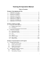
Table of Contents
Chapter 1 Introduction of PLCs
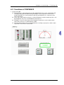
1.1
Introduction of DVP12SE.......................................................................... 1-2
1.2
Introduction of DVP20SX2........................................................................ 1-3
1.3
Introuction of DVP28SV2.......................................................................... 1-4
1.4
Introduction of DVP12SA2........................................................................ 1-5
1.5
1.6
1.7
1.8
Introduction of DVP06XA-S ...................................................................... 1-6
Introdunction of DVP04PT-S .................................................................... 1-9
Introduction of DVPEN01-SL...................................................................1-11
Introduction of DVPCOPM-SL ................................................................ 1-13
Chapter 2 Setting an HMI
2.1
Introduction of DOP-B07E515 .................................................................. 2-2
2.1.1 Hardware Specifications.................................................................... 2-2
2.1.2 Part Names ....................................................................................... 2-3
2.1.3 Pin Definition of Serial Communication ............................................. 2-4
2.2
Introduction of DOPSoft............................................................................ 2-5
2.2.1
2.2.2
2.2.3
2.2.4
Executing DOPSoft ........................................................................... 2-5
Adding New Projects ......................................................................... 2-6
Find ................................................................................................... 2-7
Replace ............................................................................................. 2-9
2.2.5 Numeric Display .............................................................................. 2-17
2.2.6 State Graphic................................................................................... 2-26
2.2.7 Numeric Entry.................................................................................. 2-40
Chapter 3 Communication and Program
3.1
Setting Communication ............................................................................ 3-2
3.1.1
Ethernet Communication................................................................... 3-2
3.1.2
RS-232 Communication .................................................................... 3-5
3.1.3
RS-485 Communication .................................................................... 3-7
3.1.4
USB Communication ....................................................................... 3-10
3.2
Uploading/Downloading a Program........................................................ 3-13
3.2.1
Uploading a Program ...................................................................... 3-13
3.2.2
Downloading a Porgram.................................................................. 3-15
i
Chapter 4 Operating a Training Kit
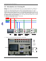
4.1
Introduction of a Training Kit .....................................................................4-2
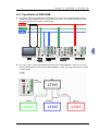
4.2
Functions of DVP12SE .............................................................................4-3
4.3
Functions of DVP28SV2 ...........................................................................4-9
4.4
Functions of DVP20SX2 .........................................................................4-20
4.5
Functions of DVP12SA2 .........................................................................4-27
Chapter 5 Examples of Programming
5.1
ROL/ROR─Neon Lamp Design.................................................................5-2
5.2
5.3
5.4
Entry/Exit Control of the Underground Car Park .......................................5-6
Recipe Setting by the CJ Instruction .........................................................5-9
PWM─Sprayer Valve Control Program ...................................................5-13
Chapter 6 Troubleshooting
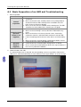
6.1
Basic Inspection of an HMI and Troubleshooting ......................................6-2
6.2
Basic Inspection of a PLC and Troubleshooting........................................6-4
6.3
6.4
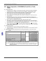
Basic Inspection of DVP06XA-S and Error Code Table ............................6-8
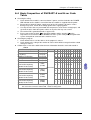
Basic Inspection of DVP04PT-S and Error Code Table.............................6-9
Appendix A Communication Setting
A.1 Communication Setting ............................................................................ A-2
A.1.1 Starting/Closing COMMGR ............................................................... A-2
A.1.2 Managing Drivers.............................................................................. A-3
A.1.3 Creating a Connection─Creating a Driver......................................... A-4
A.1.4 Creating a Connection─Configuring/Deleting a Driver .....................A-11
A.1.5 Creating a Connection Between ISPSoft and COMMGR.................A-11
A.1.6 Connecting a PLC and a Communication Port................................ A-13
A.2 Installing the USB Driver for a PLC ........................................................ A-14
A.3 Setting the USB Port on a DVP-SX2 Series PLC................................... A-19
A.4
Ethernet Port/Mini-Din Connector/RS-485 Port/Mini-USB Port/CANopen
Connector .............................................................................................. A-19
Appendix B Accessory List
B.1 Accessory List .......................................................................................... B-2
ii
iii
Chapter 1
Introduction of PLCs
The functions of PLCs and the features of modules described in this chapter help
users choose the proper models they need to perform some functions.
Table of Contents
1.1
1.2
1.3
1.4
1.5
1.6
1.7
1.8
Introduction of DVP12SE.......................................................................... 1-2
Introduction of DVP20SX2........................................................................ 1-3
Introuction of DVP28SV2.......................................................................... 1-4
Introduction of DVP12SA2........................................................................ 1-5
Introduction of DVP06XA-S ...................................................................... 1-6
Introdunction of DVP04PT-S .................................................................... 1-9
Introduction of DVPEN01-SL...................................................................1-11
Introduction of DVPCOPM-SL ................................................................ 1-13
1-1
Tr ain i n g K it O pe r a t io n Ma n ua l
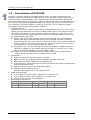
1.1
Introduction of DVP12SE
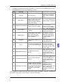
DVP-SE is a 12-point (8 DI+4 DO) PLC MPU, offering various instructions and with 16K steps
program memory, able to connect to all DVP Slim type series extension modules and high-speed
extension modules, including digital I/O (max. 480 I/O points) and analog modules (for A/D, D/A
conversion and temperature measurement). 2 points of 100 kHz and 2 points of 10 kHz high-speed
pulse output satisfy all kinds of applications. DVP-SE is small in size, and can be installed easily.
Users do not have to install any batteries in DVP-SE series PLCs. The PLC programs and the
latched data are stored in the high-speed flash memories.
1. Setting the Ethernet
The DVP-SE series PLC contains a built-in Ethernet communication port. Users have to set the
network parameter before the PLC connects to other network devices. The default parameter
setting values are 192.168.1.5 (the IP address) and 255.255.255.0 (the subnet mask). Users
can set the parameter by using DCISoft, or by using the PLC program to write the values into
the network control register (CR).
Software: Start the DCIsoft, and connect the PC to the DVP-SE series PLC through the
ehternet cable. Enter “Communication Setting” page in DCISoft, and choose “Ethernet”
communication port. Then, click “Search” to search for the picture representing the DVP-SE
series PLC. After users click the picture twice, the setting page appears. Finally, enter the
related parameters, and click “Apply” to finish the setting.
PLC program: Users use the instruction “To” to write the IP address (CR#88, 89) and the
subnet mask (CR#90, 91). For example, when the IP address is 192.168.1.5, users write
192.168 (H’C0A8) into CR#89, and .1.5 into CR#88 (H’105).
Note: When users use the instruction “From/To” to read the data from the network control
register and write the data into it, the module number is K108.
2. Specifications
Program capacity: 16k steps/Data register: 12k words
Higher execution speed compared to the competition: LD: 0.64µs, MOV: 2µs
Built-in Ethernet supports MODBUS TCP and Ethernet/IP
IP Filter function is a firewall that offers the first line of defense and provides protection from
malware and network threats
Supports DVP-S series left-side and right-side modules
No battery required. Maintenance-free.
(Real time clock operates for 15 days after power off)
3. Motion control functions
4 setos of high-speed pulse output: 100 kHz/2 sets, 10 kHz/2 sets
8 sets of high-speed pulse input: 100 kHz/2 sets, 10 kHz/6 sets
Supports 2-axis linear and arc interpolation
4. Built-in High-speed Counters
1-phase 1 input
1-phase 2inputs
2-phase 2 inputs
Sets
Bandwidth
Sets
Bandwidth
Sets
Bandwidth
2/6
100 kHz/10 kHz
2
100 kHz
1/3
50 kHz/5 kHz
1-2
Ch a pt er 1 In tr od uc t i o n of P L Cs
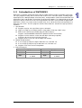
1.2
Introduction of DVP20SX2
DVP-SX2 is a 20-point (8 DI+6 DO+4 AI+2 AO) PLC MPU, offering various instructions and is with
16k steps program memory, able to connect with all Slim series extension models, including digital
input/output (max. 480 input/output extension points), analog modules (A/D, D/A transformation and
temperature units) and all kinds of new high-speed extension modules. Its 2-group high-speed (100
kHz) pulse outputs and the one new 2-axis interpolation instructions satisfy all kinds of applications.
DVP-SX2 is small in size, and it can be installed easily. Users do not have to install any batteries in
DVP-SX2 series PLCs. The PLC programs and the latched data are stored in the high-speed flash
memories.
1. Specifications
Program capacity: 16k steps/Data register: 10k words
Higher execution speed compared to the competition: LD: 0.35µs, MOV: 3.4µs
Built-in mini USB, RS-232 and RS-485 ports (Master/Slave)
Supports standard MODBUS ASCII/RTU protocol and PLC Link function
Supports real time clocl for version 2.0 and above (no battery required)
It operates for at least one week after power off.
Supports DVP-S series left-side and right-side modules
2. Motion control functions
4 sets of high-speed pulse output: 100 kHz/2 sets, 10 kHz/2 sets
8 sets of high-speed pulse input: 100 kHz/2 sets, 10 kHz/6 sets
Supports 2-axis linea and arc interpolation
3. Built-in Analog I/O
Analog input
Analog output
Points
Points
4
2
Resolution
Resolution
12-bit
12-bit
-20~20 mA or -10~10 V
0~20 mA or -10~10 V
Sepc.
Sepc.
4~20mA
4~20mA
1-3
Tr ain i n g K it O pe r a t io n Ma n ua l
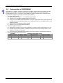
1.3
Introuction of DVP28SV2
DVP-28SV2 is a 28-point (16 inputs+12 outputs) PLC MPU, offering various instructions and with
30K (SV2) steps program memory, able to connect to all Slim type series extension models,
including digital I/O (max. 512 points), analog modules (for A/D, D/A conversion and temperature
measurement) and all kinds of high-speed extension modules.
1. Excellent motion control
High-speed pulse output: 4 sets of 200 kHz pulse output
Supports max. 4 hardware 200 kHz high-speed counters
Increases many motion control instructions to meet the applications that require high-speed
and high-precision positioning control such as labeling machines, packaging machines and
printing machines.
Offers linear/arc interpolation motion control
Provides up to 16 external interrupt pointers
2. Complete program protection
Auto backup function to prevent losing programs and data even when the battery runs out
Second copy functions provides a backup for extra insurance in the event that one set of
programs and data are damaged
Up to 4-level password protection protects your source programs and intellectual property
3. Built-in 4 hardware high-speed counters
Standard
Hardware high-speed counter
1-phase 1 input
1-phase 1 input
1-phase 2 inputs
2-phase 2 inputs
Sets Bandwidth Sets Bandwidth Sets
Bandwidth
Sets
Bandwidth
8
10 kHz
4
200 kHz
2/2 200 kHz/20 kHz 2/2 200 kHz/20 kHz
1-4
Ch a pt er 1 In tr od uc t i o n of P L Cs
1.4
Introduction of DVP12SA2
DVP-SA2 is a 12-point (8 DI+4 DO) PLC MPU, offering various instructions and with 16K steps
program memory, able to connect to all DVP-S series extension modules and high-speed extension
modules, including digital I/O (max. 480 I/O points) and analog modules (for A/D, D/A conversion
and temperature measurement). 2 points of 100 kHz and 2 points of 10 kHz high-speed pulse output
satisfy all kinds of applications. DVP-SA2 is small in size and easy to install. Users do not have to
install any batteries in DVP-SA2 series PLCs. The PLC programs and the latched data are stored in
the high-speed flash memories.
1. Specifications
Program capacity: 16K steps
Data registers: 10K words
Higher execution speed compared to the competition: LD: 0.35µs, MOV: 3.4µs
Built-in 1 RS-232 and RS-485 ports (Master/Slave)
Supports standard MODBUS ASCII/RTU protocol and PLC Link function
No battery required, maintenance-free
(Real time clock operates for 15 days after power off)
Supports DVP-S series left-side and right-side modules
2. Motion control functions
4 sets of high-speed pulse output: 100 kHz/2 sets, 10 kHz/2 sets
8 sets of high-speed putlut input:
100 kHz/2 sets, 10 kHz/6 sets, 1 group of A/B phase 50 kHz
Supports 2-axis linear and arc interpolation
3. Built-in high-speed counters
1-phase 1 input
1-phase 2 inputs
2-phase 2 inputs
Sets
Bandwidth
Sets
Bandwidth
Sets
Bandwidth
2/6
100 kHz/10 kHz
2
100 kHz
1/3
50 kHz/5 kHz
1-5
Tr ain i n g K it O pe r a t io n Ma n ua l
1.5
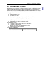
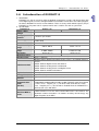
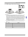
Introduction of DVP06XA-S
1. Introduction
DVP06XA-S is able to receive 4 points of analog input signals (voltage or current) and
convert them into 12-bit digital signals. DVP06XA-S receives 2 groups of 12-bit digital data
from the PLC MPU and converts them into 2 points of analog signals for output (in
voltage/current). There are 49 16-bit control registers (CR) in DVP06XA-S, and the data in it
can be read and written by using FROM/TO instructions in DVP Slim series PLC MPU
program.
The system version of DVP06XA-S can be updated via RS-485 communication. The power
unit is separate from it and is small in size and easy to install.
The user can select voltage or current input by wiring. Range of voltage input: ±10 V DC
(resolution: 5 mV). Range of current input: ±20 mA (resolution: 20 µA).
The user can also select voltage or current output by wiring. Range of voltage output: 0
V~+10 V DC (resolution: 2.5mV). Range of current output: 0 mA~20 mA (resolution: 5 µA).
2. Specifications
Mixed analog/digital
Voltage input
Current input
(A/D) module
Power supply
24 V DC (20.4 V DC~28.8 V DC) (–15%~+20%)
voltage
Analog input
4 channels per module
channel
Analog input range
±10 V
±20 mA
Digital data range
±2,000
±1,000
Resolution
12 bits(1LSB=5 mV)
11 bits (1LSB=20 µA)
Input impedance
200 kΩ and above
250 Ω
±0.5% of full scale of 25°C (77°F)
Overall accuracy
±1% of full scale during 0~55°C (32~131°F)
Response time
3 ms × channels
Isolation method
There is no isolation between channels
Absolution input
±15 V
±32 mA
range
Digital data format
2’s complement of 16-bit, (11 significant bits)
Average function
Yes (CR#2~CR#5 can be set and the range is K1~K4,096)
Self diagnostic
Upper bound and lower bound detection per channel
function
1-6
Ch a pt er 1 In tr od uc t i o n of P L Cs
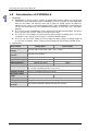
Mixed analog/digital
(A/D) module
Voltage input
Current input
Mode 0: (-10 V~+10 V); Mode 1: (-6 V~+10 V)
+20 00
Mode 0
Digital output
Mode 1
+10 00
5V
0
- 10V
6V
2V
-6V
10V
OFFSET GAI N
-1000
Conversion Curve
(Default setting:
Mode 0)
Voltage input
- 2000
Mode 2: (-12 mA~+20 mA); Mode 3: (-20 mA~+20 mA)
Mode 3
+10 00
Digital output
-20mA
Mode 2
-12mA
0
4mA
20mA
GAI N
OFF SET
- 1000
Mixed digital/analog
(D/A) module
Analog signal
output channels
Current input
Voltage output
Current output
2 channels per module
Analog output range
0~10 V
0~20 mA
Digital data range
0~4,000
0~4,000
12 bits (1LSB=2.5 mV)
12 bits (1LSB=5 µA)
Resolution
Overall accuracy
±0.5% of full scale of 25°C (77°F)
±1% of full scale during 0 ~ 55°C (32 ~ 131°F)
Output impedance
0.5 Ω or lower
Response time
3 ms × channels
Max. output current
10 mA (1 kΩ~2 MΩ)
Tolerance carried
impedance
-
-
0~500 Ω
Digital data format
2’s complement of 16-bit, (11 significant bits)
Isolation method
There is no isolation between channels.
Voltage output has short circuit protection but long period of short circuit
may cause internal wiring damage and current output break.
Protection
1-7
Tr ain i n g K it O pe r a t io n Ma n ua l
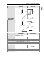
Mixed digital/analog
(D/A) module
Communication
mode
(RS-485)
Connect to
DVP-PLC MPU
in series
Voltage output
Current output
MODBUS ASCII/RTU Mode. Communication baud rate of
4,800/9,600/19,200/38,400 /57,600/115,200. For ASCII mode, date
format is 7 bits, even, 1 stop bit (7, E, 1). For RTU mode, date format is
8 bits, even, 1 stop bit (8, E, 1). The RS-485 is disabled when the
DVP06XA-S is connected in series with MPU.
When DVP06XA-S modules are connected to an MPU, the modules are
numbered from 0-7. 0 is the closest to the MPU and 7 is the furthest.
The Maximum number of modules is 8 modules and they do not occupy
any digital I/O points of the MPU.
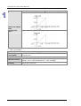
Mode 0: (0 V~+10 V); Mode 1: (2 V~+10 V)
10V
Voltage output
Mode 1
6V
5V
GAIN
2V
0
Conversion Curve
(Default setting:
Mode 0)
Mode 0
+20 00
+40 00
OFF SET
Digital input
Mode 2: (4 mA~+20 mA); Mode 3: (0 mA~+20 mA)
Current output
20mA
12mA
10mA
Mode 2
GAIN
Mode 3
4mA
0
+20 00
+40 00
OFF SET
Digit al input
3. Other specifications
Maximum power
consumption
Operation/storage
Vibration/shock
immunity
1-8
Power supply
2 W at 24VDC (20.4 V DC~28.8 V DC) (-15%~+20%), supplied by external
power
Environment
Operation: 0°C~55°C (temperature); 50~95% (humidity); pollution degree 2
Storage: -25°C~70°C (temperature); 5~95% (humidity)
International standards: IEC 61131-2, IEC 68-2-6 (TEST Fc)/IEC 61131-2 &
IEC 68-2-27 (TEST Ea)
C h a pt er 1 In tr od uc t i o n of P L C s
1.6
Introdunction of DVP04PT-S
1. Introduction
DVP04PT-S is able to receive 4 points of platinum temperature sensors and convert them into
16-bit digital signals. Besides, through FROM/TO instructions in DVP Slim series MPU program,
the data in DVP04PT-S can be read and written. There are many 16-bit control registers (CR) in
DVP04PT-S. The power unit is separate from it and is small in size and easy to install.
2. Specifications
DVP04PT-S
Celsius (°C)
Fahrenheit (°F)
Power supply
24 V DC (20.4V DC~28.8 V DC) (-15%~+20%)
voltage
Analog input
4 channels per module
channel
2-wire/3-wire PT100/Ni100/PT1000/Ni100 3850 PPM/°C (DIN 43760 JIS
Sensors type
C1604-1989)
Current excitation
1.53 mA/204.8 uA
Temperature input
-200°C~600°C
-328°F~1112°F
range
Digital conversion
K-2000~K6000
K-3280~K11120
range
Resolution
16 bits (0.1°C)
16 bits (0.1°F)
Overall accuracy
±0.6% of full scale during 0 ~ 55°C (32 ~ 131°F)
Response time
200 ms × channels
Isolation between digital and analog circuitry. There is no isolation between
channels.
500VDC between digital circuits and Ground
Isolation method
500VDC between analog circuits and Ground
500VDC between analog circuits and digital circuits
500VDC between 24VDC and Ground
Digital data format 2’s complement of 16-bit
Average function
Yes (CR#2~CR#5)
Self diagnostic
Upper bound and lower bound detection per channel
function
MODBUS ASCII/RTU Mode. Communication baud rate of
Communication
4,800/9,600/19,200/38,400 /57,600/115,200. For ASCII mode, date format
mode
is 7 bits, even, 1 stop bit (7, E, 1). For RTU mode, date format is 8 bits,
even, 1 stop bit (8, E, 1). The RS-485 is disabled when the DVP04PT-S is
(RS-485)
connected in series with MPU.
When DVP04PT-S modules are connected to an MPU, the modules are
Connect to
numbered from 0-7. 0 is the closest to the MPU and 7 is the furthest. The
DVP-PLC MPU in
Maximum number of modules is 8 modules and they do not occupy any
series
digital I/O points of the MPU.
1-9
Tr ain i n g K it O pe r a t io n Ma n ua l
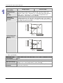
DVP04PT-S
Temperature/Digital
Value
Characteristic
Curve
Celsius (°C)
Mode of measuring Celsius temperature:
Fahrenheit (°F)
Mode of measuring Fahrenheit temperature:
3. Other specifications
Maximum power
consumption
Operation/storage
Vibration/shock
immunity
1-10
Power supply
2 W at 24 V DC (20.4 V DC~28.8 V DC) (-15%~+20%), supplied by
external power
Environment
Operation: 0°C~55°C (temperature); 50~95% (humidity); pollution degree 2
Storage: -25°C ~70°C (temperature); 5 ~ 95% (humidity)
International standards: IEC 61131-2, IEC 68-2-6 (TEST Fc)/IEC 61131-2 &
IEC 68-2-27 (TEST Ea)
C h a pt er 1 In tr od uc t i o n of P L C s
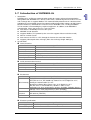
1.7 Introduction of DVPEN01-SL
1. Introduction
DVPEN01-SL is an Ethernet communication module for remote setting and communication
through WPLSoft. DVPEN01-SL is able to send E-mails, automatically correct the RTC in a PLC
and exchange data. It supports Modbus TCP communication protocol and can conduct remote
monitoring by using SCADA (Supervisor Control and Data Acquisition) software or HMI (Human
Machine Interfaces). DVPEN01-SL can be the master of Modbus TCP, sending out Modbus
TCP instructions and controlling the peripheral equipment. In addition, under MDI/MDI-X
auto-detection, it does not need to use a crossing cable.
Auto-detects 10/100 Mbps transmission speed
MDI/MDI-X auto-detection
Supports Modbus TCP protocol (at the same time supports Master and Slave mode)
Able to send out E-mails
Auto-corrects the RTC in a PLC through the Internet time correction function
Supports point-to-point data exchange (Max. data exchange length: 200 bytes)
2. Specifications
Internet interface
Item
Specifications
Interface
RJ-45 with Auto MDI/MDIX
Number of ports
1 Port
Transmission method
IEEE802.3, IEEE802.3u
Transmission cable
Category 5e
Transmission speed
10/100 Mbps Auto-Defect
Network protocol
ICMP, IP, TCP, UDP, DHCP, SMTP, NTP, MODBUS TCP
Serial communication interface
Item
Interface
Number of ports
Transmission cable
Specifications
RS-232
1 Port
DVPACAB215/DVPACAB230/DVPACAB2A30/DVPACAB2B10
Environment
Item
Specifications
ESD (IEC 61131-2, IEC 61000-4-2): 8K V Air Discharge
EFT (IEC 61131-2, IEC 61000-4-4): Power Line: 2K V, Digital I/O: 1K V,
Noise immunity Analog & Communication I/O: 1KV
Damped-Oscillatory Wave: Power Line: 1K V, Digital I/O: 1K V
RS (IEC 61131-2, IEC 61000-4-3): 26 MHz~1 GHz, 10 V/m
Operation: 0°C~55°C (temperature), 50~95% (humidity), Pollution degree 2
Environment
Storage: -25°C~70°C (temperature), 5~95% (humidity)
Vibration/shock International standard: IEC 61131-2, IEC 68-2-6 (TEST Fc)/IEC 61131-2 &
resistance
IEC 68-2-27 (TEST Ea)
Certificates
Standards: IEC 61131-2, UL508
Electrical specifications
Item
Specifications
Power supply voltage 24 V DC (-15%~20%) (Power is supplied by the internal bus of MPU.)
Power consumption
1.5 W
1 - 11
Tr ain i n g K it O pe r a t io n Ma n ua l
Item
1-12
Specifications
Insulation voltage
500 V
Weight (g)
92 (g)
C h a pt er 1 In tr od uc t i o n of P L C s
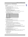
1.8 Introduction of DVPCOPM-SL
1. Introduction
DVPCOPM-SL can be used as the master in CANopen network, as well as the slave for other
masters.
As a master, DVPCOPM-SL features:
Complying with CANopen standard protocol DS301v4.02
Supporting NMT Master Service
Error control: Supporting Heartbeat/Node Guarding Protocol
Supporting PDO Service
Max. 200 RxPDOs and 390 bytes of data
Max. 200 TxPDOs and 390 bytes of data
Each slave can be allocated maximum 8 TxPDOs and 8 RxPDOs.
PDO transmission type: Supporting event trigger, time trigger, synchronous cycle, and
synchronous non-cycle
PDO mapping: Every PDO is able to map maximum 32 parameters.
Type of mapping data supported:
Storage space
Data type
1 bit
BOOL
8 bits
SINT USINT BYTE
16 bits
INT UINT WORD
32 bits
DINT UDINT REAL DWORD
64 bits
LINT ULINT LREAL LWORD
Supporting SDO Service
Number of servers: 0
Number of users: 3
Supporting standard expedited SDO transmission mode
Supporting Auto SDO function.
Able to execute maximum 20 Auto SDOs to each slave
Supporting reading/writing of data in slave by using SDO Service in the ladder diagram in
PLC
Supporting Emergency Protocol:
Able to store 5 latest Emergency messages for each slave
Able to indicate Emergency messages in slave from digital display
Able to read Emergency message through the ladder diagram in PLC
SYNC producer; Range: 0~65,535 ms
As the interface between Delta CANopenBuilder software and CANopen network
The software can configure the network directly through DVPCOPM-SL
In the auto data exchange with a PLC, the user only has to program the D register mapped
in the PLC without applygin FROM/TO instructions. When connected to a PLC, registers
after D6000 will be adopted temporarily.
As a slave, DVPCOPM-SL features:
Complying with CANopen standard protocol DS301v4.02
Supporting NMT Slave Service
Error control: Supporting Heartbeat Protocol
Supporting PDO Service: Each slave can be allocated maximum 8 TxPDOs and 8 RxPDOs.
PDO transmission type: Supporting event trigger, time trigger, synchronous cycle,
synchronous non-cycle
Supporting SDO Service
Number of servers: 1
Number of users: 0
Supporting standard expedited SDO transmission mode
1-13
Tr ain i n g K it O pe r a t io n Ma n ua l
Supporting Emergency Protocol
Able to indicate Emergency event in slave through digital display
2. Sepcifications
CANopen connection
Item
Specifications
Transmission method
CAN
Electrical isolation
500 V DC
Interface
Removable connector (5.08 mm)
Transmission cable
2 communication cables, 1 shielded cable, and 1 ground cable
Communication
Item
Message type
Baud rates
Specifications
PDO, SDO, SYNC (synchronous object), Emergency (Emergency
object), NMT
10K bps, 20K bps, 50K bps, 125K bps, 250K bps, 500K bps, 800K bps,
1M bps (bit/second)
Electrical specification
Item
Power voltage
Power consumption
Isolation voltage
Specifications
24 V DC, supplied by internal bus from PLC MPU (-15%~20%)
1.7 W
500 V
Environment
Item
Noise immunity
Opeartion
Storage
Shock/vibration
immunity
Certificates
1-14
Specifications
ESD (IEC 61131-2, IEC 61000-4-2): 8K V Air Discharge, 4K V Contact
Discharge
EFT (IEC 61131-2, IEC 61000-4-4): Power Line: 2K V, Digital I/O: 1K V
Analog & Communication I/O: 1KV
Damped-Oscillatory Wave: Power Line: 1K V, Digital I/O: 1K V
RS (IEC 61131-2, IEC 61000-4-3): 80 MHz~1000 MHz , 1.4 GHz~2.0
GHz , 10 V/m
0°C~55°C (temperature); 50~95% (humidity); pollution degree 2
-25°C~70°C (temperature); 5~95% (humidity)
International standards: IEC 61131-2, IEC 68-2-6 (TEST Fc)/IEC
61131-2 & IEC 68-2-27 (TEST Ea)
IEC 61131-2, UL508
Chapter 2
Setting an HMI
Delta DOP-BN series human machine interfaces are introduced in this chapter.
Users can create new projects and set functions by means of DOPSoft. Please
refer to DOPSoft User Manual for more information.
Table of Contents
2.1
Introduction of DOP-B07E515 .................................................................. 2-2
2.1.1
Hardware Specifications.................................................................... 2-2
2.1.2
Part Names ....................................................................................... 2-3
2.1.3
Pin Definition of Serial Communication ............................................. 2-4
2.2
Introduction of DOPSoft............................................................................ 2-5
2.2.1
Executing DOPSoft ........................................................................... 2-5
2.2.2
Adding New Projects ......................................................................... 2-6
2.2.3
Find ................................................................................................... 2-7
2.2.4
Replace ............................................................................................. 2-9
2.2.5
Numeric Display .............................................................................. 2-18
2.2.6
State Graphic................................................................................... 2-27
2.2.7
Numeric Entry.................................................................................. 2-41
2-1
Tr ain i n g K it O pe r a t io n Ma n ua l
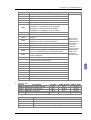
2.1 Introduction of DOP-B07E515
2.1.1
Hardware Specifications
Model
Display type
Resolution
LCD
module
Backlight
Display size
Operation system
MCU
NOR flash ROM
SDRAM
Backup memory (Bytes)
Buzzer
Sound effect output
AUX
Ethernet interface
Memory card
USB
COM1
Serial COM
COM2
port
COM3
B07E515
7” TFT LCD (65536 colors)
800 x 600 pixels
o
/
RS-422/RS-485 (has built-in isolated power circuit
RS-232 RS-485 (has built-in isolated power circuit
Function key
Perpetual calendar
Cooling method
Safety approval
(Note 5)
Voltage endurance
Power consumption
Backup battery
(Note 5)
Backup battery life
)
(Note 3)
)
/NEMA4
DC+24 V (-10%~+15%)
(Note 3)
(has built-in isolated power circuit
)
AC 500 V for 1 minute
(between charging (DC 24 V terminal) and FG terminals)
7.68 W
3 V lithium battery CR2032 × 1
It depends on the temperature used and the conditions of
o
usage, about 3 years or more at 25 C
o
o
0 C~50 C
Storage temperature
-20 C~+60 C
Vibration
2-2
IP65
Operation temperature
Ambient humidity
(Note 3)
N/A
Built-in
Natural air circulation
(Note 4)
(Note 4)
CE/UL
/KCC
Waterproof degree
Operation voltage
(Note 1)
LED Back Light (less than 10,000 hours half-life at 25 C)
141 x 105.75mm
Delta Real Time OS
32-bit RISC Micro-controller
Flash ROM 128 MB
(OS System: 30 MB/Backup: 16 MB/User Application: 82 MB)
64M bytes
16M bytes
Multi-Tone Frequency (2K~4K Hz)/85 dB
Stereo output
IEEE 802.3, IEEE 802.3u
10/100 Mbps auto-sensing
(Note 3)
(has built-in isolated power circuit
)
SD card (supports SDHC)
(Note 2)
1 USB Host
Ver 1.1/1 USB Slave Ver 2.0
RS-232 (supports hardware flow control)
o
【
o
o
】
【
o
】
10%~90% RH 0~40 C , 10%~55% RH 41 ~ 50 C ,Pollution
degree 2
≦ <8.3 Hz=Continuous: 3.5 mm,
IEC 61131-2 compliant 5 Hz f
≦≦
8.3 Hz f 150 Hz=Continuous: 1.0 g
Shock
IEC 60068-2-27compliant 15 g peak for 11 ms duration, X, Y, Z
directions for 6 times
Dimensions
(W)x(H)x(D) mm
184x144x50
Ch a pt er 2 S e tt i ng a n HM I
Model
B07E515
Panel cutout
172.4x132.4
(W)x(H)mm
Weight
Approx. 800 g
Note1: The half-life of backlight is defined as original luminance being reduced by 50% when the
maximum driving current is supplied to HMI. The life of LED backlight shown here is an
estimated value under 25oC normal temperature and humidity conditions.
Note2: USB Host port can provide up to 5 V/500 mA of power.
Note3: The withstand voltage of the isolated power circuit is 1500 V peak for 1 minute.
Note4: Some models are in the process of application to UL and KCC. For more information, please
consult our distributors.
Note5: The value of the power consumption indicates the electrical power consumed by HMI only
without connecting to any peripheral devices. In order to ensure the normal operation, it is
recommended to use a power supply which the capacity is 1.5~2 times the value of the
power consumption.
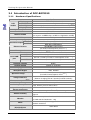
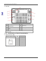
2.1.2
Part Names
Front view
A
B
Power LED indicator (Lights in green when HMI works normally)
Touch screen/Dispaly
2-3
Tr ain i n g K it O pe r a t io n Ma n ua l
Rear view
A
F
Power input terminal
USB Slave
COM2 (can be extended to
B
G
System key
COM3) (Note)
C
H
COM1
Ethernet interface (LAN)
Memory card slot/Battery
D
I
Audio output interface
cover
E
USB Host
Note: For the setting method, please refer to the pin definition of serial
communication.
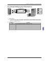
2.1.3
Pin Definition of Serial Communication
Ethernet Interface (LAN)
Ethernet interface (LAN)
Pin
1
2
3
4
5
6
7
8
Note: Blank=No connection
2-4
Contact
Ethernet
TX+
TXRX+
RX-
Ch a pt er 2 S e tt i ng a n HM I
COM1 port (Supports flow control)
COM port
PIN1
Pin
1
2
3
4
5
6
7
8
9
Contact
RS-232
RXD
TXD
GND
RTS
CTS
Note: Blank=No connection
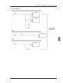
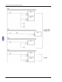
COM2 and COM3 port
COM port
PIN1
Pin
1
2
3
4
5
6
7
8
9
MODE 1
MODE 2
MODE 3
COM2 COM3 COM2 COM3 COM2 COM3
RS-232 RS-485 RS-485 RS-485 RS-232 RS-422
D+
TXD+
RXD
RXD
TXD
TXD
D+
D+
RXD+
GND
GND
GND
DTXD-
DDNote 1: Blank=No connection
Note 2: B07E515 series models do not support RS-422 flow control function.
RXD-
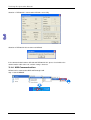
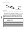
2.2 Introduction of DOPSoft
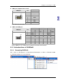
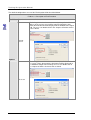
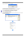
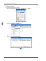
2.2.1
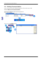
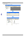
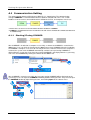
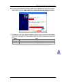
Executing DOPSoft
【Start】【All Programs】【Delta Industrial Automation】【HMI】【DOPSoft 1.00.00】
【DOPSoft 1.00.00】to execute DOPSoft.
Click
2-5
Tr ain i n g K it O pe r a t io n Ma n ua l
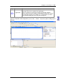
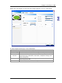
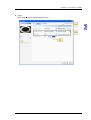
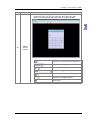
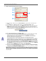
Once the software is executed, a screen with not new project will show up, as shown below.
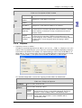
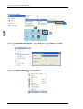
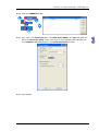
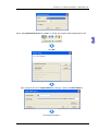
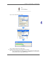
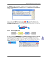
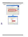
2.2.2
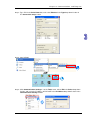
Adding New Projects
【
】
Please click
or use the system-defined hotkey Ctrl+N
to add a new project. The
Configuration Wizard of DOPSoft will pop up, which allow the user to select the model number of
HMI unit or printer and edit project and screen names. Upon completion of the basic configuration of
Next
to configure the communication protocol.
the project, please click
【
2-6
】
Ch a pt er 2 S e tt i ng a n HM I
No.
Item to note
Description
System message language
English, Traditional Chinese, and Simplified Chinese are
available for selection as the language of system index.
HMI rotation
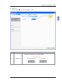
2.2.3
Select the degree for HMI rotation to be 0 degrees, 90
degrees, 180 degrees, and 270 degrees.
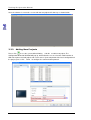
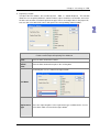
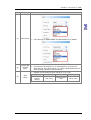
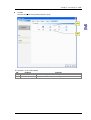
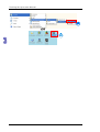
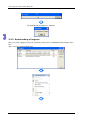
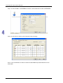
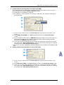
Find
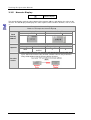
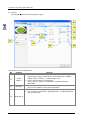
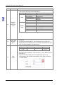
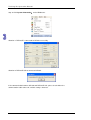
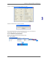
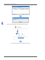
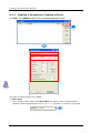
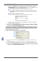
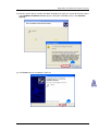
【 】 【 】
To find the designated texts and addresses, one can click
Edit Find
or use the hotkey
CTRL+F provided by the system. This function can enable the user to quickly find the results. Once
the Find function is clicked, please first enter the content to find, followed by choosing to search the
current screen or All Screen in the find selections. The find type can be used to find the text, read
address, write Address, or all address of the element, as shown below
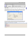
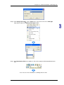
Once the method of finding is verified, click “Find” and the system will start searching for the content
that matches the entry. Once the matched content is located, the associated element will be output
to the options in the output field. When once clicks the options in the output field, the cursor will
automatically lock in this particular element, as shown below.
2-7
Tr ain i n g K it O pe r a t io n Ma n ua l
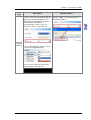
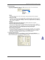
The detailed configuration screen of the Find function will be described below.
Find
《Table 2.3.1 Description of Find Function》
Find What
Enter the data content to find.
The finding is limited to the screen currently being edited. All
devices in the current screen will be compared and those that
match the find content will be displayed in the window of the output
field. The users can double-click in the “Output” to find the devices
that are found.
Current
screen
Options
The finding will cover all the screen and compare all elements in all
the screen. Those that match the find content will be displayed in
the window of output field. Similarly, the user can double-click in
the “Output” to find the elements that are found.
All screen
2-8
Ch a pt er 2 S e tt i ng a n HM I
Find
《Table 2.3.1 Description of Find Function》
Text
Compare the text entered by element
Element read
address
Element write
address
Type
All address
Match whole
word only
Checkbox
Support
multi-languag
e finding
2.2.4
Compare the read address of element
Compare the write address of element
Compare the read and write addresses of element
All entered finding contents will be compared.
If unchecked, it is a match if part of the entered contents is found.
On the contrary, if checked, it is only a match when all entered
contents match.
Only effective when the finding type is text.
If unchecked, the matching is done by only finding texts in the
current language. On the contrary, if checked, the matching will not
be limited to the current language while all languages will be
compared.
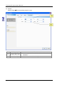
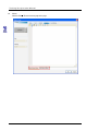
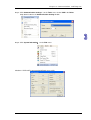
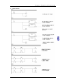
Replace
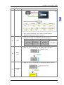
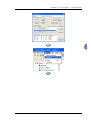
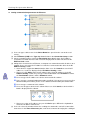
1. Replacing a text or an address
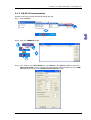
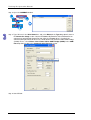
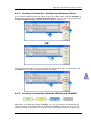
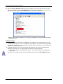
【 】 【
】
To replace a certain designated text or address, one can use
Edit Replace or use the
hotkey CTRL+R provided by the system. Enter the content of Find What, followed by choosing
Current Screen or All Screen in Options. The replacement type can be Text, Read Address, or
Write Address. The item for the Data Type is only available when the replacement type is Read
Address or Write Address, with options of Bit, WORD, or DWORD, as shown below.
The detailed configuration screen of the replacing function will be described below.
Replace
《Table 2.4-1 Example of Replace》
Find What
Enter the data content to find
Replacement
Content
Enter the data content to replace
Current
screen
Options
All screen
The search is only limited to the screen currently being edited
and all elements in this screen will be compared. Those that
match the search conditions will be substituted by order.
The search will cover all the screen and compare all elements
therein. Those that match the search conditions will be
substituted by order.
2-9
Tr ain i n g K it O pe r a t io n Ma n ua l
Replace
《Table 2.4-1 Example of Replace》
Text
Replacement
Type
Read
address
Write
address
Bit
Data Type
WORD
DWORD
Filtering
Condition
Replace those with matched text after search
Replace those with matched Read Address after search
Replace those with matched Write Address after search
The data type is only effective when the replacement type is
“Read Address” or “Write Address”, with available options of
“Bit”, “WORD”, or “DWORD”.
Selection of “Bit”, “WORD”, or “DWORD” is determined by the
format of the data type of the elements being searched.
The filtering condition is only enabled when the replacement type is “Read
Address” or “Write Address”, with available options of “Element”, “Macro”,
“Control State”, “History Buffer”, “Alarm”, “Recipe”, “Sound”, and “Screen
print setup”.
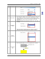
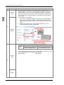
(1) Set the write address for the add and minus buttons to be $555.
(2) Execute the replacement function and enter the find content of
【$555】
【 】
is therefore selected to be 【Write Address】. When the data type of the
add and minus buttons is Word, 【Word】must be selected.
(3) Upon configuration, click 【Replace All】 to show the screen with No. (3).
(4) Click 【Yes】 in screen No. (3) and the $555 of the add and minus
and replacement content of $999 . Since the address of the add and
minus buttons are set to be the memory to write in, the replacement type
buttons will be changed to $999.
Example
2-10
Ch a pt er 2 S e tt i ng a n HM I
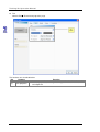
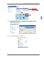
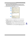
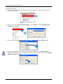
2. Replacing a station
【 】 【
】
To replace the PLC address, one can directly click
Edit Station Replace . This function
allows the user to quickly obtain the station number, replace it with the new number, and select
the link name and the associated replacement type. If there are multiple links in the project file,
one can also select other link names and replace the corresponding station numbers.
。
Replace PLC Address
《Table 2.4.2 Example of Replacing PLC Address》
Find Station
Value
Replace
Station
Value
Enter the data content to be found
Enter the data content that replaces the existing data
The Link Name for replacement can be determined based on the Base Port
created by the user, as shown in the figure below.
Link Name
Replacement
Type
There are eight categories in the replacement type available for the user to
select from, which are listed in the figure below.
2 - 11
Tr ain i n g K it O pe r a t io n Ma n ua l
Replace PLC Address
《Table 2.4.2 Example of Replacing PLC Address》
2-12
Ch a pt er 2 S e tt i ng a n HM I
Replace PLC Address
《Table 2.4.2 Example of Replacing PLC Address》
Before station number replacement
After station number replacement
Example
2-13
Tr ain i n g K it O pe r a t io n Ma n ua l
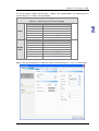
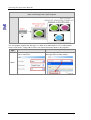
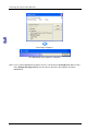
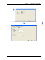
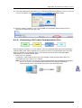
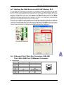
Regarding the communication setting, the user can set the model number of the controller, select
COM Port or Ethernet as the communication port, and communication parameter between the HMI
and the controller, as shown in the figure below.
Tag
2-14
Item to Note
Description
Up and down arrows
The user can use the up and down small arrows to switch
between COM port 1, COM port 2, and COM port 3.
Multi-drop
To run the system in multi-drop mode, one only needs to
open the multi-drop mode by selecting “Host” or “Client” in
“Multi-Drop”. Select “Disable” to turn off the multi-drop
communication.
Ch a pt er 2 S e tt i ng a n HM I
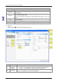
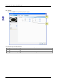
If the communication is through Ethernet, Please directly click the
【
】
【Ethernet】 icon to enter the
configuration of network controller. Click
in the
Device
page to add a new Ethernet Link,
configure parameters such as the model number of the associated controller, controller IP address,
communication delay time, timeout, and retry count, as shown in the figure below.
2-15
Tr ain i n g K it O pe r a t io n Ma n ua l
【
】
One can also switch to the
Local Host
page to configure the IP address and enable network
applications for the local host of the HMI, as shown in the figure below.
Tag
Item to Note
Description
The HMI local host indicates the IP address of the HMI.
The IP address can be manually configured or automatically
acquired.
Uncheck
【Overwrite IP】.
When this option is unchecked, the HMI will use the default IP
address 0.0.0.0.
If the user chooses not to write in the IP from the software,
he/she can still change the IP address through the system
【System Setting】【Network】.
Check 【Overwrite IP】.
screen
HMI local host
If this option is checked, it indicates the IP address is to be
changed from the software end. As a result, the user can
configure the parameters such as the IP address to write in and
name of the HMI unit.
【Overwrite IP】 and 【Obtain an IP address
automatically】.
Check
If both options are checked, it indicates that the HMI will acquire
the IP address by DHCP mode. The user can learn about the
current IP address by entering the system screen through
【System Setting】【Network】.
2-16
Ch a pt er 2 S e tt i ng a n HM I
Tag
Item to Note
Application
Description
Network application means that the HMI can be combined with the
eRemote and eServer software for applications.
If the user wants to execute the eServer or eRemote software,
he/she must first check “enable” in DOPSoft to activate the eServer
and eRemote functions in the HMI. The associated link password
and communication port also need to be configured.
Upon the completion of all configurations, please click
DOPSoft.
【Finish】 to open the project editing page in
2-17
Tr ain i n g K it O pe r a t io n Ma n ua l
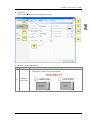
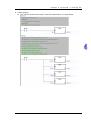
2.2.5
Numeric Display
Numeric display
The numeric display reads the value content of the memory address and displays the value on the
element. The data display also displays the state response values of other elements, such as “0” or
“1”.
Example of a Numeric Display
《Table 2.5.1 Example of a Numeric Display》
Read
memory
address
Numeric Display Element
Read memory address
$555
Data type
Properties
Word
Execution
results
2-18
Numeric Entry Element
Write memory address
$555
Numeric Display Element
Data Format
Integer Digit
Unsigned
4
decimal
Decimal Place
0
After creating elements, run “Compile” and download them to the HMI. Next,
input “100” in the numeric entry element, and the numeric entry in Numeric
Entry will be displayed in the numeric display element.
Ch a pt er 2 S e tt i ng a n HM I
【
】 and 【Double Word】. The valid range of the
The numeric display supports two data types: Word
numeric display is as shown in the table below.
Numeric Display
《Table 2.5.2 Valid Range of the Numeric Display》
Word
Double
word
Data Format
BCD
Signed BCD
Signed decimal
Unsigned decimal
Hex
Binary
Valid Range of the Numeric Display
0~9999
-999~9999
-3278~32767
0~65535
0~0xFFFF
0~0xFFFF
Data Format
BCD
Signed BCD
Signed decimal
Unsigned decimal
Hex
Binary
Valid Range of the Numeric Display
0~99999999
-9999999~99999999
-2147483648~2147483647
0~4294697295
0~0xFFFFFFFF
0~0xFFFFFFFF
Floating
0~9999999
Double-click “Numeric Display” to call out the Numeric Display properties screen as shown below.
2-19
Tr ain i n g K it O pe r a t io n Ma n ua l
Function Page
Preview
General
Text
Advanced
Position
Numeric Display
Content Description
The numeric display element does not support multistate and multilingual
data display.
Sets the read memory address, element type, element background color,
and element border color
Sets the data type, data format, integer digit, decimal place, gain, and
offset
Sets the font type, font size, font color, alignment, and content of the text
to be displayed.
Pads left zero
Sets the X-Y coordinate, width, and height of elements
General
─
Numeric Display Element general properties page
No.
(1)
(2)
2-20
Property
Read
memory
address
Data type
Function
Selects the address of the internal memory or controller register
The user can select a link name or element type. Please refer to
section 5-1 in DOPSoft User Manual for more information.
Two options: “Word” and “Double Word”
Please refer to table 2.5.2 for more information.
Ch a pt er 2 S e tt i ng a n HM I
No.
Property
(3)
Data format
(4)
Integer digit
Decimal
place
(5)
Gain
Offset
Function
If the data type is “Word”, the data formats are as follows.
If the data type is “Double Word”, the data formats are as follows.
Defines the digit of integers and the place of decimals
Instead of true decimal places, the decimal place here means the
display format. True decimal places can only be defined from this item
after selecting “Floating” in the data format.
Equation for calculating the gain and offset: y=(a) x+(b)
y
Element
numeric
display
。
a
x
b
Gain value
Register actual
value
Offset value
2-21
Tr ain i n g K it O pe r a t io n Ma n ua l
No.
Property
Function
The numeric display element will multiply the actual value in the
register by the gain value before displaying the product on the HMI
screen. The default gain is “1.0”. If the gain is “2.0”, the numeric
displayed in the element is “20” when the register actual value is “10”.
The numeric display element will add the offset value to the register
actual value before displaying the sum on the HMI screen. The default
offset is “0.0”. If offset is “1.0”, the numeric displayed in the element is
“11” when the register actual value is “10”. By contrast, if the offset is
“-1.0” the numeric displayed in the element is “9”when the register
actual value is “10”.
The following examples show
After selecting “Round off before Display”, values will be rounded off
before displaying on the numeric display element.
Gain
Offset
2-22
【Gain=2.0/Offset=-1.0】.
【Gain=2.0/Offset=1.0】 and
Ch a pt er 2 S e tt i ng a n HM I
No.
Property
(6)
(7)
(8)
Element
type
Function
There are four element types, including “Standard”, “Raised”,
“Sunken”, and “Transparent”. Users can change the element
appearance.
Standard
Raised
Sunken
Transparent
Sets element border color
If the element type is “Transparent”, the border color is disabled.
Sets element background color
If the element type is “Transparent”, the background color is disabled.
Border
color
Element
background
color
2-23
Tr ain i n g K it O pe r a t io n Ma n ua l
Text
─
Numeric Display Element text properties page
No.
(1)
2-24
Property
Text properties
Function
Sets text properties, including font type, font size, font color, and
text alignment
Ch a pt er 2 S e tt i ng a n HM I
Advanced
─
Numeric Display Element text properties page
No.
Property
Function
Leading zero is determined according to the number of digits of
an integer as shown in the example below.
Leading zero
2-25
Tr ain i n g K it O pe r a t io n Ma n ua l
Position
─
Numeric Display Element position properties page
No.
Property
(1)
X-value and Y-value
(2)
Width and height
2-26
Function
Sets the upper left X-coordinate and Y-coordinate of
elements
Sets the element width and height
Ch a pt er 2 S e tt i ng a n HM I
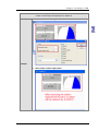
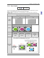
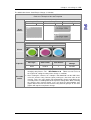
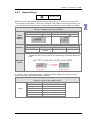
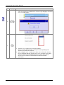
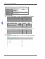
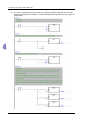
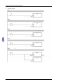
2.2.6
State Graphic
State graphic
Users can create various state pictures in the state graphic to read state data from the selected
address, in order to display the selected state pictures on the HMI.
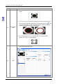
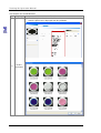
Examples of the three applications are described below. The table below shows “Auto Picture
Change” is “No”.
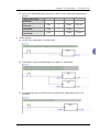
Example of the State Graphic
《Table 2.5.3 Example of the State Graphic》
State Graphic Element
Read address
$326
Numeric Entry Element
Write address
$326
Read
address
State 0
Set the State Graphic
State 1
State 2
Picture
State Graphic Element
Properties
Data Type
Data Format
State Counts
Auto Picture
Change
Word
Unsigned
decimal
3
No
After creating the element, run “Compile” and download it to the HMI. Next,
input a value in the numeric entry element. Then, the state graphic will display
the state pictures corresponding to the input value.
Execution
results
2-27
Tr ain i n g K it O pe r a t io n Ma n ua l
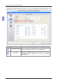
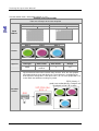
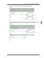
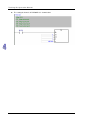
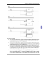
The table below shows “Auto Graph Change” is “Yes”.
Example of the State Graphic
《Table 2.5.4 Example of the State Graphic》
State Graphic Element
Read address
$326
Numeric Entry Element
Write address
$326
Read
address
State 0
Set the State Graphic
State 1
State 2
Picture
State Graphic Element
Properties
Execution
results
2-28
Data Type
Data Format
State Counts
Auto Picture
Change
Word
Unsigned
decimal
3
Yes
After creating the element, run “Compile” and download it to the HMI. Next,
input a non-zero value in the numeric entry element. Then, the state graphic
will automatically change and display the selected pictures according to the
defined picture change time. If the input value is “0”, the state graphic will reset
to the initial state without executing any action.
Ch a pt er 2 S e tt i ng a n HM I
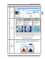
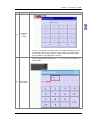
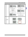
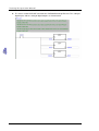
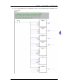
The table below shows “Auto Picture Change” is Variation.
Example of the State Graphic
《Table 2.5.5 Example of the State Graphic》
State Graphic Element
Read address
$326
Numeric Entry Element
Write address
$326
Numeric Entry Element
Write address
$327
Read
address
State 0
Set the State Graphic
State 1
State 2
Picture
State Graphic Element
Properties
Data Type
Data Format
State Counts
Auto Picture
Change
Word
Unsigned
decimal
3
Variation
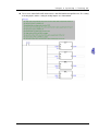
The read address in the state graphic element represents the register for
【
Execution
results
】
changing state pictures. The
Read Address+1
allows users to access to
the register for setting the auto picture change as variation.
After creating the element, run “Compile” and download it to the HMI. Next,
select the numeric entry element {$327} and input a non-zero value in the
element. Then, the state graphic will automatically change and display the
selected pictures according to the defined picture change time. When selecting
the numeric entry element {$326}, users can input the corresponding state
graphic data in the element. If the numeric entry element {$327}is “0”, the state
graphic will stop the auto picture change.
2-29
Tr ain i n g K it O pe r a t io n Ma n ua l
Example of the State Graphic
《Table 2.5.5 Example of the State Graphic》
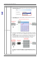
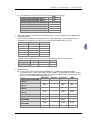
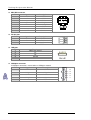
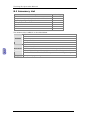
The state graphic supports four data types as shown in the table below. If users need to add or
remove state counts, simply add or reduce state counts from State Counts in the properties.
Data
State Counts
Memory Address
Type
If the data type is “Word”, users can If the data type is “Word”, “Word” is the
select 1-256 states.
data type of the memory address.
Word
2-30
Ch a pt er 2 S e tt i ng a n HM I
Data
Type
LSB/LSB
(Support
State 0)
State Counts
Memory Address
If the data type is “LSB”, the data in the
register is first converted into the binary
data. Next, the present object state is
determined according to the element
with the lowest non-zero bit.
If the data type is “LSB”, users can
select 1-16 states, except “State 0”.
If the data type is “LSB” or “LSB (Support
State 0)”, “Word” is also the data type of
the memory address.
If users wish to display “State 0”, please
select “LSB (Support State 0)”.
If users select “LSB”, the element will
display “black” when State=0.
2-31
Tr ain i n g K it O pe r a t io n Ma n ua l
Data
Type
State Counts
Memory Address
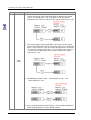
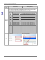
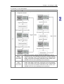
The examples in the following table show how the state value is determined with the
lowest non-zero element after converting from a decimal value into a binary value.
There are also examples demonstrating how DOPSoft determines the state value
displayed with the lowest bit when the decimal values are 3 and 7.
Decimal
Binary
Sate Value
State=0 when all bits are 0
0
0000000000000000
LSB (Support State 0) must be selected
【
LSB/LSB
(Support
State 0)
1
2
3
4
7
8
16
32
64
128
256
512
1024
2048
4096
8192
16384
32768
0000000000000001
0000000000000010
0000000000000011
0000000000000100
0000000000000111
0000000000001000
0000000000010000
0000000000100000
0000000001000000
0000000010000000
0000000100000000
0000001000000000
0000010000000000
0000100000000000
0001000000000000
0010000000000000
0100000000000000
1000000000000000
If the data type is “Bit”, only 2 states
are available.
Bit
2-32
】
The lowest non-zero bit is bit 0, State=1.
The lowest non-zero bit is 1, State=2.
The lowest non-zero bit is bit 0, State=1.
The lowest non-zero bit is bit 2, State 3.
The lowest non-zero bit is bit 0, State=1.
The lowest non-zero bit is bit 3, State=4.
The lowest non-zero bit is bit 4, State=5.
The lowest non-zero bit is bit 5, State=6.
The lowest non-zero bit is bit 6, State=7.
The lowest non-zero bit is bit 7, State=8.
The lowest non-zero bit is bit 8, State=9.
The lowest non-zero bit is bit 9, State=10.
The lowest non-zero bit is bit 10, State=11.
The lowest non-zero bit is bit 11, State=12.
The lowest non-zero bit is bit 12, State=13.
The lowest non-zero bit is bit 13, State=14.
The lowest non-zero bit is bit 14, Statep15.
The lowest non-zero bit is bit 15, State=16.
If the data type is “Bit”, “Bit” is the data type
of the memory address.
Ch a pt er 2 S e tt i ng a n HM I
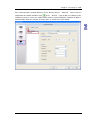
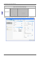
Double-click “State Graphic” to call out the State Graphic properties screen as shown below.
The State Graphic function pages are described below.
State Graphic
Function Page
Content Description
Preview
Views the multistate data, but does not support multilingual data display
Sets the read address, foreground color, and transparent color
General
Sets the data type, data format, state counts, auto picture change, and
picture change time
Sets the picture bank name, the alignment, the stretch mode, and the
Picture
picture transparent color
Position
Sets the X-Y coordinate, width, and height of the element
2-33
Tr ain i n g K it O pe r a t io n Ma n ua l
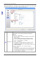
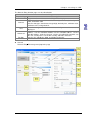
General
─
State Graphic Element general properties page
The functions are described below.
No.
Property
Function
Selects the address of the internal memory or controller register. The
memory type changes based on the selected data type, including
“Word”, “LSB”, and “Bit”, as shown in table 2.5.6.
Read
(1)
address
Selects the link name or element type
Please refer to section 5-1 in DOPSoft User Manual for more
information.
Four options: “Bit”, “Word”, “LSB”, and “LSB (Support State 0)”
Data type
(2)
Please refer to table 2.5.6 for more information.
The data format can only be selected when the data type is “Word”.
These formats include “BCD”, Signed Decimal”, “Unsigned Decimal”,
and “Hexadecimal”.
(3)
2-34
Data format
Ch a pt er 2 S e tt i ng a n HM I
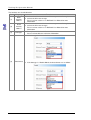
No.
Property
Function
(4)
State counts
(5)
Auto picture
change
Please refer to the examples in table 2.5.3~table 2.5.5 for more
information about the application of the auto picture change.
The picture change time ranges from 100-3000 ms.
Sets the foreground color
If the transparent color is “Yes”, the foreground color is disabled.
(6)
(7)
Sets the total state count of the state graphic elements
If the data type is “Word”, users can select 1-256 states; if the data
type is “LSB”, users can select 16 states; if the data type is “LSB
(Support State 0)”, users can select 17 states; if the data type is “Bit”,
users can select 2 states. Please refer to table 2.5.6 for more
information.
There are 3 options for the auto picture change: “Yes”, “No”, and
“Variation”
Picture
change time
Foreground
color
2-35
Tr ain i n g K it O pe r a t io n Ma n ua l
No.
Property
Function
After selecting “Yes” for the transparent color, the result is as shown
below.
Users can select any color in the picture to become transparent with
the transparent color. By clicking the Transparent Color icon
and
then the black button section, DOPSoft will omit coloring the black
section in the picture to make it transparent.
(8)
(9)
2-36
Transparent
color
State
By selecting the transparent color for both the element and the
picture, the result is as shown below.
Users can preview or change the parameter of all button element
states by changing the state.
Ch a pt er 2 S e tt i ng a n HM I
Graph
─
State Graphic Element graph properties page
2-37
Tr ain i n g K it O pe r a t io n Ma n ua l
The functions are described below.
No.
Property
Function
The default picture bank name is “None”. Users can select in the built-in
bank the picture to be displayed from the pull-down.
(1)
2-38
Picture
bank name
Ch a pt er 2 S e tt i ng a n HM I
No.
Property
Function
Sets the picture alignment with the alignment options.
Alignment
The stretch modes include “Fill”, “Keep Aspect Ratio”, and “Actual Size”.
Fill
Keep Aspect Ratio
Actual Size
In the “Keep Aspect
Ratio” mode, the
In the “Actual Size”
In the “Fill” mode,
selected picture will fit
mode, the picture will
the selected picture
in the display area
be displayed in its
will fill up the entire
proportionally
original size in the
display area.
according to the
display area.
picture ratio.
If “Process all state pictures” is selected, the system assumes that each
element has multiple entries of state data, and some pictures may be
unable to fill the entire display area. By selecting this item, users will not
need to set individual pictures to save time from editing.
Sets a color in the picture to transparent
(2)
Stretch
mode
In this case, by clicking the Transparent Color icon
and then the
orange part of the loom, DOPSoft will omit all orange parts in the picture
and turn them into transparent.
(3)
Selecting
the
transparent
color
2-39
Tr ain i n g K it O pe r a t io n Ma n ua l
Position
─
State Graphic Element position properties page
The functions are described below.
No.
Property
(1)
X-value and Y-value
(2)
Width and height
2-40
Function
Sets the upper left X-coordinate and Y-coordinate of elements
Sets the element width and height
Ch a pt er 2 S e tt i ng a n HM I
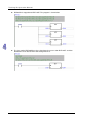
2.2.7
Numeric Entry
Numeric entry
With the numeric keypad provided by the numeric entry element, users can input a value to the
selected write memory address. Next, after reading this value with the element read memory, such
as the data display element, this value is displayed on the HMI. Please refer to table 2.6.1 below.
Example of the Numeric Entry
《Table 2.6.1 Example of the Numeric Entry》
Read
memory
address
Numeric Entry Element
Write memory address
$555
Data Type
Properties
Word
Data Display Element
Read memory address
$555
Numeric Entry Element
Data Format
Integer Digit
Unsigned
4
decimal
Decimal Place
0
After creating the element, compile and download it to the HMI. Next, input
“100”with the numeric entry element, the data display element will display this
value.
Execution
results
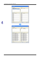
The numeric entry supports two data types, “Word” and “Double Word”. The valid range of the
numeric entry data is described in table 2.6.2 below.
Numeric Entry
《Table 2.6.2 Numeric Entry Valid Range》
Word
Data Format
BCD
Signed BCD
Signed decimal
Unsigned decimal
Hex
Binary
Data Valid Range
0~9999
-999~9999
-32768~32767
0~65535
0~0xFFFF
0~0xFFFF
2-41
Tr ain i n g K it O pe r a t io n Ma n ua l
Numeric Entry
《Table 2.6.2 Numeric Entry Valid Range》
Double Word
Data Format
BCD
Signed BCD
Signed decimal
Unsigned decimal
Hex
Binary
Floating
Data Valid Range
0~99999999
-9999999~99999999
-2147483648~2147483647
0~4294697295
0~0xFFFFFFFF
0~0xFFFFFFFF
0~9999999
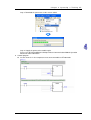
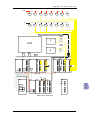
Double-click “Numeric Entry” to call out the Numeric Entry properties screen as shown below.
2-42
Ch a pt er 2 S e tt i ng a n HM I
The Numeric Entry function pages are described below.
Numeric Entry
Function Page
Content Description
Preview
Supports neither multistate nor multilingual data display
Sets the read memory address, write memory address, style, background
color, and border color
General
Sets the data type, data format, integer digit, decimal place, minimum value,
maximum value, and gain/offset
Sets the font type, font size, font color, and alignment of the text to be
Text
displayed
Sets the method of enabling input, sets the interlock state, sets the interlock
address, sets the activation method, sets the activation address, sets the
Advanced
invisible address, pads the left zero, sets the exceeding limit reminder, sets
the user security level, sets the low security, and hides characters
Position
Sets the X-Y coordinate, width, and height of elements
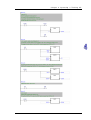
General
─
Numeric Entry Element general properties page
2-43
Tr ain i n g K it O pe r a t io n Ma n ua l
The functions are described below.
No.
Property
Function
Selects the address of the internal memory or controller register
Write
Selects the link name or style
(1)
memory
Please refer to section 5-1 in DOPSoft User Manual for more
address
information.
Selects the address of the internal memory or controller register
Read
Selects the link name or stype
(2)
memory
Please refer to section 5-1 in DOPSoft User Manual for more
address
information.
Two options: “Word” and “Double Word”
(3)
Data type
Please refer to table 2.6.2 for more information
If the data type is “Word”, the data formats are as follows.
(4)
2-44
Data format
If the data type is “Double Word”, the data formats are as follows.
Ch a pt er 2 S e tt i ng a n HM I
No.
Property
(4)
Function
The editing numeric keypad allows users to adjust the numeric
keypad size, title size, font size, font type, font color or the data
display, and background color of the numeric keypad window.
Editing
numeric
keypad
Selects the system numeric keypad size
Sets the title height
Sets the font size
Sets the font type
Sets the font color
Selects the background color
Default size
2-45
Tr ain i n g K it O pe r a t io n Ma n ua l
No.
Property
(5)
Minimum
value/
Maximum
value
(6)
Integer digit
Decimal
place
(7)
2-46
Gain
Offset
Function
The data valid range of the minimum value and the maximum value is
subject to the data type and the data format.
Data Type
Data Format
Data Valid Range
BCD
0~9999
Signed BCD
-999~9999
Signed decimal
-32768~32767
Word
Unsigned decimal
0~65535
Hex
0~0xFFFF
Binary
0~0xFFFF
BCD
0~99999999
Signed BCD
-9999999~99999999
Signed decimal
-2147483648~2147483647
Double
Unsigned decimal
0~4294967295
word
Hex
0~0xFFFFFFFF
Binary
0~0xFFFFFFFF
Floating
0~9999999
Users can define the integer digits and decimal places to be
displayed.
Instead of true decimal places, the decimal place here means the
display format. True decimal places can only be defined form this item
after selecting “Floating” in the data format.
Equation for calculating the gain and offset: y=(a) x+(b)
y
a
x
b
Calculation
Offset/Gain
Gain value
Input value
results
values
If the gain or offset defined is a decimal, please select “Floating” in the
data format.
The numeric entry provides the estimation button for users to
understand the gain and offset calculations more simply and clearly
as shown below.
Ch a pt er 2 S e tt i ng a n HM I
No.
Property
Function
After selecting “Round off”, values will be rounded off before
displaying on the numeric display element.
There are four styles, including “Standard”, “Raised”, “Sunken”, and
“Transparent”. Users can change the element appearance.
Standard
Raised
Sunken
Transparent
Sets the border color of elements.
When the style is “Transparent”, the border color is disabled.
Sets the background color of elements
When the style is “Transparent”, the background color is disabled.
(8)
(9)
(10)
Style
Border
color
Background
color
2-47
Tr ain i n g K it O pe r a t io n Ma n ua l
Text
─
Numeric Entry Element text properties page
The functions are described below.
No.
Property
Function
Sets text properties, including the font type, font size, font color, and
(1)
Text properties
text alignment
2-48
Ch a pt er 2 S e tt i ng a n HM I
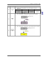
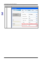
Advanced
─
Numeric Entry Element advanced properties page
The functions are described below.
No.
Property
Function
Padding the left zero is determined according to the number of digits of
an integer as shown in the example below.
(1)
Padding
the left zero
2-49
Tr ain i n g K it O pe r a t io n Ma n ua l
No.
Property
(2)
Info the
over range
message
(3)
User
security
level
2-50
Function
If “Yes” is selected for “Info the over range message”, when the input
value exceeds this range defined, an error message will pop up to remind
users as shown below.
Sets the users security level of element activities
Only users with equal or higher security level corresponding to the
element can activate the element.
After setting the users security level, when users activate the element,
the password box will pop up and request users to input the password.
(The password can be changed form the password setup element.
Please refer to section 5-7 in DOPSoft User Manual for more
information.)
Ch a pt er 2 S e tt i ng a n HM I
No.
Property
(3)
Setting the
low
security
Function
(4)
If “Yes” is selected for “Set Low Security”, the HMI automatically sets the
security to the lowest level every time users input the password. When
users activate the element again, they will be requested to input again
the password corresponding to the element.
If “Yes” is selected for “Hide Character”, all numbers input from the
numeric keypad will be displayed as “***”, i.e. characters are hidden, as
shown below.
Displaying
the asterisk
2-51
Tr ain i n g K it O pe r a t io n Ma n ua l
No.
Property
(5)
Function
The input modes include “Touch Popup”, “Active Non-Popup”, and
“Touch Non-Popup”. “Touch Popup” is the default input method for the
numeric entry elements.
“Touch Popup” means after touching a numeric element, the numeric
keypad will pop up.
No numeric keypad will pop up for both “Active Non-Popup” and “Touch
Non-Popup”. Users must create an additional keypad element to operate
the HMI.
“Active Non-Popup” must be used along with the interlock address. Set
the interlock address of the numeric entry element as $44.0, create a
maintained element, and set its write memory address as $44.0.
Input mode
Like the case of “Active Non-Popup”, no keypad will pop up in “Touch
Non-Popup”. Therefore, an additional keypad is needed to input numeric
data.
2-52
Ch a pt er 2 S e tt i ng a n HM I
No.
Property
Function
2-53
Tr ain i n g K it O pe r a t io n Ma n ua l
No.
Property
Interlock
state
Function
The interlock address allows users to operate an element form this
particular address. It must be used along with the interlock state. If the
interlock state is “OFF”, this means the interlock address is operable
when the interlock state is “OFF”. In contrast, when the interlock state is
“ON”, this means the interlock address is operable when the interlock
state is “ON”.
The operations are as follows.
I First, create a maintained button and set its write memory address as
$44.0. Next, set its write memory as $555 from the numeric entry
element and the interlock address of the character entry element as
$44.0.
II To make the numeric entry element $555 operable, press the
maintained button $44.0 to enable $555.
(6)
Interlock
address
The trigger types include “Before Writing” and “After Writing”.
Before Writing
After Writing
Trigger
The activation bit is ON
Values are changed before
type
before changing values.
the activation bit is ON.
As the activation function only sets the trigger address to ON, users must
set the trigger address to OFF before re-activation.
Before writing:
After writing:
Trigger
type
(7)
Trigger
2-54
Ch a pt er 2 S e tt i ng a n HM I
No.
Property
Function
(8)
When the invisible address is “ON”, the button element is hidden, and the
corresponding function is disabled.
Invisible
address
2-55
Tr ain i n g K it O pe r a t io n Ma n ua l
No.
2-56
Property
Function
Ch a pt er 2 S e tt i ng a n HM I
Position
─
Numeric Entry Element position properties page
The functions are described below.
No.
Property
Function
(1)
X-value and Y-value Sets the upper left X-coordinate and Y-coordinate of elements
(2)
Width and height
Sets the element width and height
2-57
Tr ain i n g K it O pe r a t io n Ma n ua l
Macro
─
Numeric Entry Element macro properties page
2-58
Ch a pt er 2 S e tt i ng a n HM I
The functions are described below.
No.
Property
Function
The Before Execute Macro process and the After Execute Macro process are
diagrammed below.
(1)
Before
executing
the macro
After
executing
the macro
When users touch the button element, the HMI will first run the
commands in the corresponding macro before running the button
action. If the button state is not changed by means of touching the
button (using external controller commands or other macros), the
HMI will not run the corresponding macro commands.
After users touch the button element, the HMI will first run the
button action before running the commands in the corresponding
macro. If the button state is not changed by means of touching the
button (using external controller commands or other macros), the
HMI will not run the corresponding macro commands.
2-59
Chapter 3
Communication and Program
The methods of connecting a PLC are described in this chapter. Users can
upload/download a program through different communication types.
Table of Contents
3.1
Setting Communication ............................................................................ 3-2
3.1.1
Ethernet Communication................................................................... 3-2
3.1.2
RS-232 Communication .................................................................... 3-5
3.1.3
RS-485 Communication .................................................................... 3-7
3.1.4
USB Communication ....................................................................... 3-10
3.2
Uploading/Downloading a Program........................................................ 3-14
3.2.1
Uploading a Program ...................................................................... 3-14
3.2.2
Downloading a Porgram.................................................................. 3-16
3-1
Tr ain i n g K it O pe r a t io n Ma n ua l
3.1 Setting Communication
A PLC can communicate with ISPSoft through Ethernet, RS-232, RS-485, or USB.
3.1.1 Ethernet Communication
ISPSoft can be connected to DVP12SE through Ethernet.
Step 1: Start COMMGR.
Step 2: Open the COMMGR window.
3-2
Ch a pt er 3 C om m unic a ti o n a nd Pr o gr am
Step 3: Type “EN” in the Drive Name box, and select Ethernet in the Type drop-down list box in
the Connection Setup section.
Step 4: Start ISPSoft.
Step 5: Click Communication Settings… on the Tools menu. Select EN in the Driver drop-down
list box, and select the IP address of DVP12SE in the IP Address drop-down list box in the
Communication Setting window.
3-3
Tr ain i n g K it O pe r a t io n Ma n ua l
Step 6: Click System Information
… on the PLC menu.
Situation 1: DVP12SE is connected to ISPSoft successfully.
Situation 2: DVP12SE fails to connect to ISPSoft.
If the communication between ISPSoft and DVP12SE fails, please check whther the
commnucation cable comes off, and the setting is incorrect.
3-4
Ch a pt er 3 C om m unic a ti o n a nd Pr o gr am
3.1.2 RS-232 Communication
ISPSoft can be connected to DVP28SV2 through RS-232.
Step 1: Start COMMGR.
Step 2: Open the COMMGR window.
Step 3: Type “RS232” in the Drive Name box, select RS232 in the Type drop-down list box in the
Connection Setup section, and select the corresponding communication port in the COM
Port drop-down list box in the Communication Protocol section.
3-5
Tr ain i n g K it O pe r a t io n Ma n ua l
Step 4: Start ISPSoft.
Step 5: Click Communication Settings… on the Tools menu. Select RS232 in the Driver
drop-down list box in the Communication Setting window.
Step 6: Click System Information
3-6
… on the PLC menu.
Ch a pt er 3 C om m unic a ti o n a nd Pr o gr am
Situation 1: DVP28SV2 is connected to ISPSoft successfully.
Situation 2: DVP28SV2 fails to connect to ISPSoft.
If the communication between ISPSoft and DVP28SV2 fails, please check whther the
commnucation cable comes off, and the setting is incorrect.
3.1.3 RS-485 Communication
ISPSoft can be connected to DVP28SV2 through RS-485.
Step 1: Start COMMGR.
3-7
Tr ain i n g K it O pe r a t io n Ma n ua l
Step 2: Open the COMMGR window.
Step 3: Type “Driver3” in the Drive Name box, and select RS232 in the Type drop-down list box in
the Connection Setup section. Connect IFD6500 to DVP28SV2 so that DVP28SV2 can
communicate with ISPSoft through RS-485. After the IFD6500 driver is installed, the
communication port which will be used is called Silicon Labs CP210x USB to UART Bridge
(COM6). Please select Silicon Labs CP210x USB to UART Bridge (COM6) in the COM
Port drop-down list box in the Communication Protocol section.
Step 4: Start ISPSoft.
3-8
Ch a pt er 3 C om m unic a ti o n a nd Pr o gr am
Step 5: Click Communication Settings… on the Tools menu. Select RS485 in the Driver
drop-down list box, and select 1 in the Station Address drop-down list box in the
Communication Setting window.
Step 6: Click System Information
… on the PLC menu.
3-9
Tr ain i n g K it O pe r a t io n Ma n ua l
Situation 1: DVP28SV2 is connected to ISPSoft successfully.
Situation 2: DVP28SV2 fails to connect to ISPSoft.
If the communication between ISPSoft and DVP28SV2 fails, please check whther the
commnucation cable comes off, and the setting is incorrect.
3.1.4 USB Communication
ISPSoft can be connected to DVP12SE through USB.
Step 1: Start COMMGR.
3-10
Ch a pt er 3 C om m unic a ti o n a nd Pr o gr am
Step 2: Open the COMMGR window.
Step 3: Type “USV” in the Drive Name box, select USB (Virtual COM) in the Type drop-down list
box in the Connection Setup section, and select the corresponding communication port
in the COM Port drop-down list box in the Communication Port section.
Step 4: Start ISPSoft.
3 - 11
Tr ain i n g K it O pe r a t io n Ma n ua l
3-12
Ch a pt er 3 C om m unic a ti o n a nd Pr o gr am
Step 5: Click Communication Settings… on the Tools menu. Select USB in the Driver
drop-down list box in the Communication Setting window.
Step 6: Click System Information
… on the PLC menu.
Situation 1: DVP12SE is connected to ISPSoft successfully.
3-13
Tr ain i n g K it O pe r a t io n Ma n ua l
Situation 2: DVP28SV2 fails to connect to ISPSoft.
If the communication between ISPSoft and DVP28SV2 fails, please check whther the
commnucation cable comes off, and the setting is incorrect.
Please refer to appendix A for more information aout setting USB communication.
3.2 Uploading/Downloading a Program
3.2.1 Uploading a Program
If users want to know the program stored in a PLC, they can connect the PLC to a PC, and upload
the program through ISPSoft.
Step 1: Select a communication type.
3-14
Ch a pt er 3 C om m unic a ti o n a nd Pr o gr am
Step 2: After Upload from PLC on the toolbar is clicked, the program will be uploaded to the PC.
Click OK.
Type a project name in the Project Name box, and type a path in the Drive/Path box.
Percentage of progress
3-15
Tr ain i n g K it O pe r a t io n Ma n ua l
The uploading of the program is complete.
3.2.2 Downloading a Porgram
After users write a program, they can connect the PC to a PLC, and download the program to the
PLC.
Step 1: Select a communication type.
3-16
Ch a pt er 3 C om m unic a ti o n a nd Pr o gr am
…
Step 2: Click Change PLC Type on the Tools menu, and select a PLC in the PLC Type
drop-down list box in the Change PLC Type window.
Step 3: After Download to PLC on the toolbar is clicked, the program will be downloaded to the
PLC.
Users have to select checkboxes according to their needs.
3-17
Tr ain i n g K it O pe r a t io n Ma n ua l
Percentage of progress
The downlading of the program is complete.
Note: If users want to download a program, the PLC selected in the PLC Type drop-down list box
in the Change PLC Type window must be correct. Otherwise the program can not be
downloaded.
3-18
Ch a pt er 3 C om m unic a ti o n a nd Pr o gr am
MEMO
3-19
Chapter 4
Operating a Training Kit
Delta slim types of PLCs can exchange data with a master station through Ethernet,
CANopen, or RS-485. The slave stations are used with a temperature
measurement module, a digital input/output module, an analog input/output module,
a high-speed output function, and a high-speed count function.
Table of Contents
4.1
4.2
4.3
4.4
4.5
Introduction of a Training Kit..................................................................... 4-2
Functions of DVP12SE............................................................................. 4-3
Functions of DVP28SV2........................................................................... 4-9
Functions of DVP20SX2......................................................................... 4-20
Functions of DVP12SA2......................................................................... 4-27
4-1
Tr ain i n g K it O pe r a t io n Ma n ua l
4.1 Introduction of a Training Kit
Delta slim types of PLCs can exchange data with a master station through Ethernet, CANopen, or
RS-485.
The HMI can exchange data with the master station DVP12SE through Ethernet, and exchange
data with slave station through DVP12SE. The master station DVP12SE functions as a data
collection center. It communicates with the slave station DVP20SX2 through Ethernet, with the slave
station DVP28SV2 through CANopen, with the slave station DVP12SA2 through RS-485. The slave
stations are used with a temperature measurement module, a digital input/output module, an analog
input/output module, a high-speed output function, and a high-speed count function. Please refer to
the following sections for more information.
An equivalent communication structure is shown below.
1. Equivalent communication structure
2. The devices on the panel of the training kit are shown below.
16SP
PT100
sensor
12SE
06XA
OUT
4-2
06XA
IN
Ch a pt er 4 O p er a t i ng a Tr a i n in g K i t
4.2 Functions of DVP12SE
The HMI is connected to DVP12SE through Ethernet. It can exchange data with the master
station DVP12SE through Ethernet, and exchange data with slave station through DVP12SE.
An equivalent Ethernet network is shown below.
The value in C0 is written into DVP28SV2, DVP12SA2, and DVP20SX2, and then the values
written into DVP28SV2, DVP12SA2, and DVP20SX2 are read. The page displayed on the HMI
is shown below.
4-3
Tr ain i n g K it O pe r a t io n Ma n ua l
The HMI displays the devices which are involved in data exchange.
HMI
Data source
C0
Device in which data read from
D6039
DVP28SV2 is stored
Device in which data read from
D1484
DVP12SA2 is stored
Device in which data read from
D104
DVP20SX2 is stored
1. Data exchange table
The master station DVP12SE exchanges data with DVP28SV2 through CANopen.
Master station/Slave station
Master
Direction
Slave
PLC
DVP12SE
DVP28SV2
Writing data into DVP28SV2
D6289
→
D6039
Reading data from DVP28SV2
D6039
←
D6289
The master station DVP12SE exchanges data with DVP12SA2 through RS-485.
Master station/Slave station
Master
Direction
Slave
PLC
DVP12SE
DVP12SA2
Writing data into DVP12SA2
D1498
→
D202
Reading data from 12SA2
D1484
←
D104
The master station DVP12SE exchanges data with DVP20SX2 through Ethernet.
Master station/Slave station
Master
Direction
Slave
PLC
DVP12SE
DVP20SX2
Writing data into DVP20SX2
D202
→
D102
Reading data from DVP20SX2
D104
←
D204
2. Control program
The RS-485 communication setting of the master station DVP12SE is shown below.
4-4
Ch a pt er 4 O p er a t i ng a Tr a i n in g K i t
DVP12SA2 is mapped onto DVP12SE. The program is shown below.
The master station DVP12SE communicates with DVP28SV2 through CANopen. The
setting of a high-speed pulse output flag and the setting of a pulse clearing flag are shown
below.
4-5
Tr ain i n g K it O pe r a t io n Ma n ua l
4-6
The master station DVP12SE communicates DVP20SX2 through Ethernet. The setting of
digital inputs and the setting of digital outputs are shown below.
Ch a pt er 4 O p er a t i ng a Tr a i n in g K i t
The master station DVP12SE communicates with DVP20SX2 through Ethernet. The setting
of analog inputs and the setting of analog outputs are shown below.
4-7
Tr ain i n g K it O pe r a t io n Ma n ua l
4-8
The master station DVP12SE communicates with DVP12SA2 through RS-485, and with
DVP28SV2 through DVPCOPM-SL, and with DVP20SX2 through Ethernet. The program is
shown below.
Ch a pt er 4 O p er a t i ng a Tr a i n in g K i t
4.3 Functions of DVP28SV2
1. Page on the HMI
DVPCOPM-SL is connected to the left side of DVP28SV2. The master station DVP12SE
exchanges data with DVP28SV2 through CANopen. The temperature measurement
module DVP04PT-S is connected to the right side of DVP28SV2. It is used to measure
room temperature.
Users can set the frequency of pulses sent by DVP28SV2, and the number of pulses sent
by DVP28SV2. They can use DVP28SV2 to count pulses/
DVP04PT-S measure room temperature through a temperature sensor, and the room
temperature measures is displayed on the HMI.
The page which displays the use of DVP28SV2 to send high-speed pulses and the room
temperature measured is shown below.
4-9
Tr ain i n g K it O pe r a t io n Ma n ua l
An equivalent CANopen network is shown below.
The HMI displays the devices which are involved in data exchange.
HMI
Reading the temperature sent
D6032
by channels 1 in DVP04PT-S
Setting the frequency of
D6282
pulses sent by DVP28SV2
Setting the number of pulses
D6284
sent by DVP28SV2
High-speed count
D6033
Pulse output flag
M0
Count clearing flag
M1
2. The steps of setting the HMI are as follows.
Step 1: Set the frequency of pulses sent by DVP28SV2, and the number of pulses sent by
DVP28SV2
Step 2: Press the Pulse output button so that the state of the button is RUN.
Step 3: Press the Remove count value button so that the state of the button is ON. The state of
the Pulse output button becomes STOP. If users want to resume the output of pulses,
they have to set the Remove count value button to OFF, otherwise the Pulse output
button can not be set to RUN.
Note: When pulses are sent, users can set the frequency of pulses sent by DVP28SV2, but they
can not change the number of pulses sent by DVP28SV2.
4-10
Ch a pt er 4 O p er a t i ng a Tr a i n in g K i t
3. Setting DVPCOPM-SL
The master station DVP12SE communicates with DVP28SV2 through DVPCOPM-SL,
DVP28SV2
DVP12SE
HMI
Reading the temperature sent
D6282
→
D6032
D6032
by channels 1 in DVP04PT-S
Frequency of pulses
D6032
←
D6282
D6282
Number of pulses
D6034
←
D6284
D6284
High-speed count
D6283
→
D6033
D6033
Pulse output flag
M0
←
M0
D6036
D6286
Count clearing flag
M1
←
M1
Writing data into DVP28SV2
D6039
←
D6289
Reading data from DVP28SV2
D6289
→
D6039
D6039
4. Setting hardware
Step 1: Setting a station address
It is used to set the node address of DVPCOPM-SL on a CANopen network. The node
addresses which can be used range from 1 to 7F. (0 and 80~FF can not be used.)
Setting
Description
Available nodes on a
1~7F
CANopen network
0, 80~FF
Unavailable nodes on a
CANopen network
Note:
Please use a slotted screwdriver to turn the knobs with care, and do not scrape them.
When the power supply is cut off, a node address can be set. After the setting of a node
address is complete, DVPCOPM-SL can be supplied with power.
Step 2: Setting the same baud rate
It is used to set the transmission rate of DVPCOPM-SL on a CANopen network. The relation
between transmission rates and maximum communication distances are shown below.
Transmission Maximum communication
DR 2 DR 1 DR0
rate
distance
OFF OFF OFF
10 kbps
5000 m
OFF OFF ON
20 kbps
2500 m
OFF ON OFF
50 kbps
1000 m
OFF ON ON
125 kbps
500 m
ON OFF OFF
250 kbps
250 m
ON OFF ON
500 kbps
100 m
ON ON OFF
800 kbps
50 m
ON ON ON
1 Mbps
25 m
IN 0
Reserved
Note:
Please use a slotted screwdriver to turn the knobs with care, and do not scrape them.
When the power supply is cut off, a node address can be set. After the setting of a node
address is complete, DVPCOPM-SL can be supplied with power.
Step 3: Supplying the power again
5. Setting the software
CANopen Builder is used to set the work mode of the module and the devices which can be
4 - 11
Tr ain i n g K it O pe r a t io n Ma n ua l
involved in data exchange.
Setting the work mode of the module
Step 1: Set the communication between the software and the module.
Step 2: Click Online on the Network menu.
Step 3: Select a communication channel.
4-12
Ch a pt er 4 O p er a t i ng a Tr a i n in g K i t
Step 4: Set the work mode of the module.
Click Download on the Network menu.
Step 5: Supply the power to the module again.
Setting the devices which can be involved in data exchange
Step 1: After the work mode of the module is set, users have to connect the software to the
master station. After the users click Online on the Network menu, the node which is
connected to the master station will be scanned
4-13
Tr ain i n g K it O pe r a t io n Ma n ua l
Step 2: Set the devices which can be involved in data exchange.
Increase devices which can be involved in data exchange.
4-14
Ch a pt er 4 O p er a t i ng a Tr a i n in g K i t
4-15
Tr ain i n g K it O pe r a t io n Ma n ua l
4-16
Ch a pt er 4 O p er a t i ng a Tr a i n in g K i t
Step 3: Download the parameters to the master station.
Step 4: Supply the power to the module again.
Please refer to DVPCOMPM-SL CANopen Master Communication Module Operation
Manual for more information.
6. Control program
Set the channel 1 in the temperature measurement module to PT100 mode.
4-17
Tr ain i n g K it O pe r a t io n Ma n ua l
The slave station DVP28SV2 receives data from the master station DVP12SE, and then
DVP28SV2 sends data to DVP12SE through CANopen.
Set the high-speed output Y0 in DVP28SV2. X0 uses the high-speed counter C241.
4-18
Ch a pt er 4 O p er a t i ng a Tr a i n in g K i t
4-19
Tr ain i n g K it O pe r a t io n Ma n ua l
4.4 Functions of DVP20SX2
1. Page on the HMI
DVPEN01-SL is connected to the left side of DVP20SX2. The master station DVP12SE
exchanges data with DVP20SX2 through Ethernet. It is used to measure room temperature.
An equivalent Ethernet network is shown below.
4-20
Users can set the voltage output of D/A CH0. The voltage sent is in the range of -10 V to 10
V. The users can also set the current output of D/A CH1. The current sent is in the range of
0 mA to 20 mA.
Yn connected to Xn (n=0~5). When Yn is set to ON, Xn is ON. When Yn is set to OFF, Xn is
OFF. The page displayed on the HMI is shown below.
Ch a pt er 4 O p er a t i ng a Tr a i n in g K i t
The HMI displays the devices which are involved in data exchange.
HMI
Voltage input of A/D CH0 (D1110)
D300
Current input of A/D CH1 (D1111)
D301
Voltage output of D/A CH0 (D1116)
D400
Current output of D/A CH1 (D1117)
D401
States of X0~X5
M10~M15
States of Y0~Y5
M30~M35
Setting Y0~Y5
M50~M55
2. Connection between analog inputs and analog outputs, and connection between digital inputs
and digital outputs
There are four A/D channels, two D/A channels, eight digital inputs, and six digital outputs in
DVP20SX2. The digital inputs X0~X5 are connected to the digital outputs Y0~Y5.
DI
Connection
DO
X0
←→
Y0
X1
←→
Y1
X2
←→
Y2
X3
←→
Y3
X4
←→
Y4
X5
←→
Y5
The A/D channels CH0 and CH1 are connected to the D/A channels CH0 and CH1.
Mode
A/D
Connection
D/A
Voltage mode
CH0
←→
CH0
Current mode
CH1
←→
CH1
3. Setting Ethernet
Users have to connect DVP12-SE, DVPEN01-SL, and DVS to a computer through
networking cables, and use DCISoft to set the IP address of DVPEN01-SL and the devices
which can be involved in data exchange. The master station DVP12SE communicates with
the slave station DVP20SX2 through Ethernet.
DVP20SX2 Direction
DVP12SE
HMI
Voltage input of A/D CH0
D200
→
D100
D300
(D1110)
Current input of A/D CH1
D201
→
D101
D301
(D1111)
Voltage output of D/A CH0
D100
←
D200
D400
(D1116)
Current output of D/A CH1
D101
←
D201
D401
(D1117)
States of X0~X5
D202
→
D102
M10~M15
States of Y0~Y5
D203
→
D103
M30~M35
Writing data into
D102
←
D202
DVP20SX2
Reading data from
D204
→
D104
D104
DVP20SX2
Setting Y0~Y5
D103
←
D203
M50~M55
4-21
Tr ain i n g K it O pe r a t io n Ma n ua l
4. Setting the software
Step 1: Search for the node on the network.
4-22
Ch a pt er 4 O p er a t i ng a Tr a i n in g K i t
Step 2: Set the IP address of DVP12SE.
4-23
Tr ain i n g K it O pe r a t io n Ma n ua l
Step 3: Set the IP address of DVPEN01-SL which is connected to the left side of DVP20SX2.
Step 4: Set the devices which can be involved in data exchange.
Please refer to DVPEN01-SL Ethernet Communication Module operation Manual for more
information.
4-24
Ch a pt er 4 O p er a t i ng a Tr a i n in g K i t
5. Control program
The setting of analog inputs and the setting of analog outputs are shown below.
4-25
Tr ain i n g K it O pe r a t io n Ma n ua l
DVP20SX2 is mapped onto DVP12SE. The program is shown below.
The slave station DVP20SX2 receives data from the master station DVP12SE, and then
DVP20SX2 sends data to DVP12SE through Ethernet.
4-26
Ch a pt er 4 O p er a t i ng a Tr a i n in g K i t
4.5 Functions of DVP12SA2
1. Page on the HMI
DVP06XA-S and DVP16SP are connected to the right side of DVP12SA2. An equivalent
RS-485 network is shown below.
When the digital input Xm on the panel is set to ON, the digital output Ym on the panel is ON.
When the digital input Xm on the panel is set to OFF, the digital output Ym on the panel is
OFF. (m=0~7)
DVP06XA-S and DVP16SP are connected to the right side of DVP12SA2. The page
displayed on the HMI is shown below.
4-27
Tr ain i n g K it O pe r a t io n Ma n ua l
The HMI displays the devices which are involved in data exchange.
HMI
States of X0~X7 on DVP16SP
M20~M27
States of Y0~Y7 on DVP16SP
Y20~Y27
2. Connection between analog inputs and analog outputs, and connection between digital inputs
and digital outputs
Users can use VR1 to control the voltage sent to DVP06XA-S, and use VR2 to control the
current sent to DVP06XA-S. CH1 in DVP06XA-S is set to voltage input mode. The external
voltage detected by CH1 is converted into the corresponding lsb. CH5 is set to voltage
output mode. The lsb is converted into the corresponding voltage. The voltage is sent by
CH5. CH2 is set to voltage input mode. The external voltage detected by CH2 is converted
into the corresponding lsb. CH6 is set to current output mode. The lsb is converted into the
corresponding current. The current is sent by CH6.
The digital inputs X0~X7 on DVP16SP correspond to the switches X0~X7 on the panel, the
digital outputs Y0~Y7 on DVP16SP correspond to the LED indicators Y0~Y7 on the panel.
3. Setting RS-485
Set DVP12SE to master mode.
Set DVP12SA2 to slave mode.
Please refer to chapter 2 in DVP-PLC Application Manual for more information.
4-28
Ch a pt er 4 O p er a t i ng a Tr a i n in g K i t
The master station DVP12SE communicates with the slave station DVP12SA2 through
RS-485.
DVP12SA2 Direction
DVP12SE
HMI
States of X0~X7 on
D100
→
D1480
M20~M27
DVP16SP
States of Y0~Y7 on
D101
→
D1481
Y20~Y27
DVP16SP
Writing data into
D202
←
D1498
DVP12SA2
Reading data from
D104
→
D1484
D1484
DVP12SA2
4. Control program
Set the slave station address of DVP12SA2.
DVP12SA2 is mapped onto DVP12SE. The program is shown below.
The digital inputs X0~X7 on DVP16SP corresponds to the digital outputs Y0~Y7 on
DVP16SP.
4-29
Tr ain i n g K it O pe r a t io n Ma n ua l
4-30
The setting of channels in DVP06XA-S is shown below.
Ch a pt er 4 O p er a t i ng a Tr a i n in g K i t
The setting of digital inputs in DVP06XA-S and the setting of digital outputs DVP06XA-S are
shown below.
4-31
Tr ain i n g K it O pe r a t io n Ma n ua l
4-32
The slave station DVP12SA2 receives data from the master station DVP12SE, and then
DVP12SA2 sends data to DVP12SE through RS-485.
Chapter 5
Examples of Programming
Simple examples of programming are provided in this chapter. Users can test the
function of a training kit by means of these examples. Please refer to DVP-PLC
Application Examples of Programming for more information.
Table of Contents
5.1
5.2
5.3
5.4
ROL/ROR─Neon Lamp Design ................................................................ 5-2
Entry/Exit Control of the Underground Car Park....................................... 5-6
Recipe Setting by the CJ Instruction......................................................... 5-9
PWM─Sprayer Valve Control Program................................................... 5-13
5-1
Tr ain i n g K it O pe r a t io n Ma n ua l
5.1 ROL/ROR─Neon Lamp Design
Y0
Y10
Y1
Y2
Y11 Y12
Y3
Y13
Y4
Y14
Y5
Y15
Y6
Y16
Y7
Y17
X0 Right
X1
Left
X2
Reset
1. Control purpose
After the Right Rotation button is pressed, the 16 neon lamps will be turned on for 200
milliseonds in the order Y0~Y7 and Y10~Y17.
After the Left Rotation button is pressed, the 16 neon lamps will be turned on for 200
milliseonds in the order Y17~Y10 and Y7~Y0.
Users do not have to press the Reset button when switching between the Right Rotation
button and the Left Rotation button.
After the Reset button is pressed, all the neon lamps will be turned off.
2. Devices
Device
Function
Right Rotation button
X0
X0=ON when the button is pressed.
Left Rotation button
X1
X1=ON when the button is pressed.
Reset button
X2
X2=ON when the button is pressed.
200 ms timer
T0/T1
Time base: 100 ms.
Y0~Y17
16 neon lamps
5-2
Ch a pt er 5 Ex am pl es of Pr o gr am m ing
3. Control program
5-3
Tr ain i n g K it O pe r a t io n Ma n ua l
5-4
Ch a pt er 5 Ex am pl es of Pr o gr am m ing
4. Program description
After the Right Rotation button is pressed, X0 will be turned ON, and the instruction ZRST
will be executed. When ZRST is executed, Y0~Y17 and M10~M11 are reset to OFF. When
the instruction SET is executed, Y0 and M10 are set to ON. When M10 is ON, the
instruction TMR is executed. After 200 milliseconds, T0 will be turned ON, and the
instruction ROL will be executed. When ROL is excuted, Y1 is ON. After ROL is executed,
the instruction RST will be executed. When RST is executed, T0 is reset.
In the next scan cycle, T0 starts counting again. After 200 milliseconds, ROL will be
executed again, and Y2 will be ON. Y0~Y17 are turned ON for 200 milliseconds in order.
The use of the Left Rotation button is similar to the use of the Right Rotation button.
However, the Left Rotation button uses the instruction ROR to turn ON the neon lamps in
the order Y17~Y10 and Y7~Y0.
After the Reset button is pressed, X2 will be turned ON, Y0~Y17 and M10~M11 will be reset,
and all the neons will be turned OFF. ZRST put after the rising edge-triggered contact
ensures that the neon lamps are turned ON from Y0 or Y17.
5-5
Tr ain i n g K it O pe r a t io n Ma n ua l
5.2 Entry/Exit Control of the Underground Car Park
Red Light Green Light
Y1
Y2
X1
Entry/Exit of the Ground Floor
Red Light Green Light
Si nga
Y1
Y2
X2
l L
an
e P
as
sa
ge
Entry/Exit of the Basement
1. Control purpose
The entry/exit of the underground car park is a single lane passage which needs the traffic
lights to control the cars. Red lights prohibit cars entering or leaving while green lights allow
cars to enter or leave.
When a car enters the passage from the entry of the ground floor, the red lights both on the
ground floor and the basement will be ON, and the green lights will be OFF. Any car entering
or leaving is prohibited during the process till the car passes through the passage
completely. When the passage is clear, the green lights will be ON again and allow other
cars entering from the ground floor or the basement.
Similarly, when a car leaves the basement and enters the passage, any car entering or
leaving is prohibited till the car passes from the passage to the ground completely.
When a PLC runs, the initial setting of traffic lights will be green lights ON and red lights
OFF.
2. Devices
Device
Function
Photoelectric switch at the ground floor entry/exit
X1
X1 is ON when a car passes.
Photoelectric switch at the basement entry/exit
X2
X2 is ON when a car passes.
M1
M1 will be ON for one scan cycle if a car from the ground floor passes X1.
M2
M2 will be ON for one scan cycle if a car from the basement passes X1.
M3
M3 will be ON for one scan cycle if a car from the basement passes X2.
M4
M4 will be ON for one scan cycle if a car from the ground floor passes X2
M20 is ON when a car is in the process of entering the passage from the
M20
ground floor.
M30 is ON when a car is in the process of entering the passage from the
M30
basement.
Y1
Red lights at the entry/exit of the ground floor and the basement
Y2
Green lights at the entry/exit of the ground floor and the basement
5-6
Ch a pt er 5 Ex am pl es of Pr o gr am m ing
3. Control program
5-7
Tr ain i n g K it O pe r a t io n Ma n ua l
4. Program description
The ground floor and the basement share the same red light signal Y1 and green light
signal Y2.
The key of the program is to judge whether the car is entering or leaving the passage at the
ground floor entry/exit when M1 is ON to activate Y1 because [PLS M1] will be executed in
both entering and leaving conditions. Therefore, the confirming signal M20 is required for
confirming that the car is entering the passage from the ground floor.
Also, it needs to be judged whether the car is entering or leaving the passage at the
basement entry/exit when M3 is ON because [PLS M3] will be executed in both entering
and leaving conditions. Therefore, the confirming signal M30 is required for confirming that
the car is entering the passage from the basement.
5-8
Ch a pt er 5 Ex am pl es of Pr o gr am m ing
5.3 Recipe Setting by the CJ Instruction
Pulse Output
Y10
C2
Y0
C0
PLS
COMSIGN
Forward / Reverse
X1 X4
Stroke 1
X2
Stroke 2
X3
Stroke 3
DVP12SC
Delta ASDA Servo
1. Control purpose
A Delta DVP12SC series PLC controls 3 stroke distances of Delta ASDA servo by sending
pulses. Users can choose an adequate stroke distance to meet the working requirement by
pressing 3 individual switches.
2. Devices
Device
Function
X1
X1 is ON when the Stroke 1 switch is pressed.
X2
X2 is ON when the Stroke 2 switch is pressed.
X3
X3 is ON when the Stroke 3 switch is pressed.
X4
X4 is ON when the servo positioning switch is pressed.
Y0
Pulse direction control
Y10
Pulse output point
5-9
Tr ain i n g K it O pe r a t io n Ma n ua l
3. Control program
5-10
Ch a pt er 5 Ex am pl es of Pr o gr am m ing
4. Program description
If X1 is ON, X2 is OFF, and X3 is OFF, the execution of the program will jump from [CJ P1]
to P1. After the execution of the program jumps from [CJ P1] to P1, the constant K10000 will
be stored in D0, that is, the first stroke distance will be selected, and the execution of the
program will jump to P4 to get ready to output pulses.
If X2 is ON, X1 is OFF, and X3 is OFF, the execution of the program will jump from [CJ P2]
to P2. After the execution of the program jumps from [CJ P2] to P2, the constant K20000 will
be stored in D0, that is, the second stroke distance will be selected, and the execution of the
program will jump to P4 to get ready to output pulses.
If X3 is ON, X1 is OFF, and X2 is OFF, the execution of the program will jump from [CJ P3]
to P3. After the execution of the program jumps from [CJ P3] to P3, the constant K30000 will
be stored in D0, that is, the third stroke distance will be selected, and the execution of the
program will jump to P4 to get ready to output pulses.
If X1 is OFF, X2 is OFF, and X3 is OFF, the instruction [CJ p4] will be executed, and the
execution of the program will jump to P4 directly to get ready to output pulses.
If X4 is ON, the instruction [DDRVI D0 K10000 Y10 Y0] will be executed, that is, Y10 will
output a certain number of pulses on a frequency of 100 KHz (the value in D0 is the number
of pulses output), and Y0 will control the pulse direction. Since the distance the servo motor
5 - 11
Tr ain i n g K it O pe r a t io n Ma n ua l
operates is proportional to the number of pulses recieved, the object of controlling the
distance the servo operates can be achieved by setting the number of pulses output by the
PLC.
5-12
Ch a pt er 5 Ex am pl es of Pr o gr am m ing
5.4 PWM─Sprayer Valve Control Program
X2
25%
X3
X4
100%
50%
X0
START
X1
STOP
1. Control purpose
In order to reduce the energy lost during the gradual shut-down/start-up process, we apply
the switching method which immediately turns on and turns off the current valve. The
switching method is somewhat like cutting off a current, and is therefore called a clipper.
However, in the practical application we put a transistor between the power and the motor to
perfom the function of a clipper. A pulse signal will be applied to the base of the transistor so
as to generate a pulse current between the base and the emitter. The input voltage of motor
is in proportion to the ton/toff value. Therefore, the motor voltage could be adjusted by
modulating the ton/toff value. There are various methods for modulating this value, and the
most common one is to adjust the time (ton) for which the valve is ON rather than adjusting
the number of times the valve is ON during a a particular length of time. The method is
called PWM (Pulse-width modulation).
Users can control the the degree to which the sprayer vale is opened by adjusting the ton/toff
value of PWM (24 V). The opening degrees which can be selected are 25%, 50%, and
100%.
2. Devices
Device
Function
X0
X0 is ON when the START button is pressed.
X1
X1 is ON when the STOP button is pressed.
X2
X2 is ON when the 25% button is pressed.
X3
X3 is ON when the 50% button is pressed.
X4
X4 is ON when the 100% button is pressed.
Y0
Controlling the degree to which the the valve is opened
The degree to which the the valve is opened is stored in
D0
D0.
5-13
Tr ain i n g K it O pe r a t io n Ma n ua l
3. Control program
4. Program description
In this program, the degree to which the sprayer valve is opened is controlled by the value in
D0. Opening degree=ton/toff =D0/(K1000-D0)
After the START button is pressed, X0 will be ON. When X0 si turned ON, M0 is set to ON.
When M0 is ON, the water spraying system is ready. The water spraying systemd will start
spraying water after the corresponding opening degree button is pressed.
If the 25% button is pressed (X2 is ON), the value in D0 will be K200, D0/(K1000-D0)=0.25,
and the opening degree will be 25%.
If the 50% button is pressed (X3 is ON), the value in D0 will be K333, D0/(K1000-D0)=0.50,
and the opening degree will be 50%.
If the 25% button is pressed (X4 is ON), the value in D0 will be K500, D0/(K1000-D0)=1,
and the opening degree will be 100%.
After the STOP button is pressed, X1 will be ON. When X1 is turned ON, the value in D0
becomes 0, D0/(K1000-D0)=0, the opening degree becomes 0, and the system start flag
M0 are reset to OFF.
5-14
Chapter 6
Troubleshooting
The malfunctions which may occur when a system operates, the reasons for the
malfunctions, and possible solutions are described in this chapter.
Table of Contents
6.1
6.2
6.3
6.4
Basic Inspection of an HMI and Troubleshooting ..................................... 6-2
Basic Inspection of a PLC and Troubleshooting ....................................... 6-4
Basic Inspection of DVP06XA-S and Error Code Table............................ 6-8
Basic Inspection of DVP04PT-S and Error Code Table ............................ 6-9
6-1
Tr ain i n g K it O pe r a t io n Ma n ua l
6.1 Basic Inspection of an HMI and Troubleshooting
1. Basic inspection
Item
1.
General
inspection
2.
3.
1.
2.
Inspection before
operation
(Power is not
supplied.)
Inspection before
operation
(Power is
supplied.)
3.
4.
5.
1.
2.
3.
Content
Periodically inspect the screws of the connection between the HMI
and device.
Make sure that oil, water, metallic particles or any foreign objects
do not fall inside the HMI, control panel or ventilation slots and
holes. As these will cause damage.
Make sure of the correct installation of the control panel. The HMI
should be free from airborne dust, harmful gases or liquids.
Make sure that all wiring terminals are correctly insulated.
Make sure that all wiring is correct, otherwise malfunctions may
occur.
Make sure that there are not any unused screws, metal strips,
conductive materials, and inflammable materials inside the HMI.
Lower electromagnetic interference when device are influenced by
it.
Make sure that the external voltage supplied to the HMI is correct.
Check whether the power LED indicator is ON.
Check whether the communication among devices is normal.
Please contact our local distributor or Delta sales representatives if
there are any abnormal conditions.
2. Communication error code
If a communication error is detected, the corresponding error message will be shown on the
HMI screen. “Communication Error 3” in the red frame in the figure below is an error message.
6-2
Ch a pt er 6 Tr o ub l es h o o ti n g
If an HMI can not communicate with a controller, users can refer to the following table for more
information about the error code shown on the screen.
Error Communication error
Reason
Troubleshooting
code
message
Strengthen the
equipment’s immunity to
0x02
Unknown
Noise interference
noise, and use shielded
cables.
The wiring, the PLC station
number, and the values of the
Please check whether the
0x03
NoResponse
communication parameters
related setting is incorrect.
(baudrate, parity bit, data bits,
stop bit) are incorrect.
Please check whether the
When the HMI checks the PLC PLC checksum is
0x05 ControllerCheckSumError
checksum, an error is found.
incorrect. Users usually
have to use PLC software.
Please check whether the
The command sent to the PLC
0x06
CommandError
command sent by HMI is
is incorrect.
supported by the PLC.
Please check whether the
The PLC address from which
PLC address set by the
data is read, or the PLC
HMI is not supported by
0x07
AddressError
address into which data is
the PLC, or data can not
be written into this
written is incorrect.
address.
Pleas make sure of the
The data written into the PLC is
0x08
ValueError
values which can be
incorrect.
accepted by the PLC.
Please check whether the
The CTS pin in HMI does not
CTS pin in the HMI is
0x0A
NoCTS
receive the RTS signal from the connected to the RTS pin
in the PLC, or PLC sends
PLC.
the RTS signal.
Please check whether the
station number of the HMI
The HMI station number is
exceeds the legal range,
0x0E HMIStationNumberError
incorrect.
or is the same as the
station number of another
station.
Please check whether the
station number of the PLC
The PLC station number is
exceeds the legal range,
0x0F PLCStationNumberError
incorrect.
or is the same as the
station number of another
station.
Please check whether the
The bottom communication of
COM port used can
the HMI is incorrect. The COM
function normally, or
port is not opened correctly, or
0x10 UARTCommunicateFail
simply the operation of the
the HIM works so hard that the
HMI, e.g. delete the
COM port can not function
instructions ALARM and
normally.
MACRO.
If the program in an HMI is destroyed or lost, please connect the HMI to a computer, and download
the program again. Please refer to chapter 2 for more information.
6-3
Tr ain i n g K it O pe r a t io n Ma n ua l
6.2 Basic Inspection of a PLC and Troubleshooting
The malfunctions which commonly occur in a PLC and troubleshooting are described in the tables
below.
1. System malfunction
Symptom
Troubleshooting and Corrective Actions
1.
Check the power supply wiring.
2.
Check whether the power supplied to the PLC control units is in
the range of the rating.
3.
Be sure to check the fluctuation in the power supply.
4.
Disconnect the power supply wiring to the other devices if the
power supplied to the PLC control unit is shared with them.
If
the LEDs on the PLC control unit are turned ON at this
All LEDs are OFF
moment, the capacity of the power supply is not enough to
control other devices as well. Prepare another power supply for
other devices or increase the capacity of the power supply.
5.
If the POWER LED still does not light up when the power is ON
after the above corrective actions, the PLC should be sent back
to the dealer or the distributor whom you purchased the product
from.
1.
If the ERROR LED is flashing, the problem may be an invalid
commands, communication error, invalid operation, or missing
instructions, error indication is given by self-checking function
and corresponding error code and error step are stored in
special registers. The corresponding error codes can be read
from the WPLSoft or HPP. Error codes and error steps are stored
in the following special registers.
Error code: D1004
ERROR LED is
Error step: D1137
flashing
2.
If the connections between the PLCs fail and the LED flashes
rapidly, this indicates the DC 24 V power supply is down. Please
check for possible DC 24 V overload.
3.
The LED will be steady if the program loop execution time is over
the preset time (set in D1000), check the programs or the WDT
(Watch Dog Timer). If the LED remains steady, download user
program again and then power up to see if the LED will be OFF.
If not, please check whether there is any noise interference or
any foreign object in the PLC.
6-4
Ch a pt er 6 Tr o ub l es h o o ti n g
Symptom
Diagnosing Input
Malfunction
Diagnosing
Output
Malfunction
Troubleshooting and Corrective Actions
When input indicator LEDs are OFF,
1.
Check the wiring of the input devices.
2.
Check that the power is properly supplied to the input terminals.
3.
If the power is properly supplied to the input terminal, there is
probably an abnormality in the PLC’s input circuit. Please contact
your dealer.
4.
If the power is not properly supplied to the input terminal, there is
probably an abnormality in the input device or input power
supply. Check the input device and input power supply.
When input indicator LEDs are ON,
1.
Monitor the input condition using a programming tool. If the input
monitored is OFF, there is probably an abnormality in the PLC’s
input circuit. Please contact your dealer.
2.
If the input monitored is ON, check the program again. Also,
check the leakage current at the input devices (e.g., two-wire
sensor) and check for the duplicated use of output or the
program flow when a control instruction such as MC or CJ is
used.
3.
Check the settings of the I/O allocation.
When output indicator LEDs are ON,
1.
Check the wiring of the loads.
2.
Check whether the power is properly supplied to the loads.
3.
If the power is properly supplied to the load, there is probably an
abnormality in the load. Check the load again.
4.
If the power is not supplied to the load, there is probably an
abnormality in the PLC’s output circuit. Pleas contact your
dealer.
When output indicator LEDs are OFF,
1.
Monitor the output condition using a programming tool. If the
output monitored is turned ON, there is probably a duplicated
output error.
2.
Forcing ON the output using a programming tool. If the output
indicator LED is turned ON, go to input condition check. If the
output LED remains OFF, there is probably an abnormality in the
PLC’s output circuit. Please contact your dealer.
2. Error code in D1004: The error code stored in D1004 is a hexadecimal code.
After you write the program into the PLC, the illegal use of operands (devices) or incorrect
syntax in the program will result in flashing of ERROR indicator and M1004 = ON. In this case,
you can find out the cause of the error by checking the error code (hex) in special register
D1004. The address where the error occurs is stored in the data register D1137. If the error is a
general loop error, the address stored in D1137 will be invalid.
Error code
0001
0002
0003
0102
0202
0302
0401
0403
0501
。
Description
Operand bit device S exceeds the valid range.
Label P exceeds the valid range or duplicated.
Operand KnSm exceeds the valid range.
Interrupt pointer I exceeds the valid range or duplicated.
Instruction MC exceeds the valid range.
Instruction MCR exceeds the valid range.
Operand bit device X exceeds the valid range.
Operand KnXm exceeds the valid range.
Operand bit device Y exceeds the valid range.
Action
Check D1137.
(Check the
Error step
number.)
Re-enter the
instruction
correctly.
6-5
Tr ain i n g K it O pe r a t io n Ma n ua l
Error code
0503
0601
0604
0801
0803
0B01
0D01
0D02
0D03
0D04
0D05
0D06
0D07
0D08
0D09
0D0A
0D0B
0E01
0E04
0E05
0E18
0E19
0E1A
0E1B
0E1C
0F04
0F05
0F06
0F07
0F08
0F09
0F0A
0F0B
0F0C
0F0D
1000
10EF
2000
6-6
Description
Operand KnYm exceeds the valid range.
Operand bit device T exceeds the valid range.
Operand word device T register exceeds the limit.
Operand bit device M exceeds the valid range.
Operand KnMm exceeds the valid range.
Operand K, H available range error
DECO operand misuse
ENCO operand misuse
DHSCS operand misuse
DHSCR operand misuse
PLSY operand misuse
PWM operand misuse
FROM/TO operand misuse
PID operand misuse
SPD operand misuse
DHSZ operand misuse
IST operand misuse
Operand bit device C exceeds the valid range.
Operand word device C register exceeds the limit.
DCNT operand CXXX misuse
BCD conversion error
Division error (divisor=0)
Device use is out of range (including index registers E, F).
Negative number after radical expression
FROM/TO communication error
Operand word device D register exceeds the limit.
DCNT operand DXXX misuse
SFTR operand misuse
SFTL operand misuse
REF operand misuse
Improper use of operands of WSFR, WSFL instructions
The number of times TTMR/STMR is used exceeds the
range.
The number of times SORT is used exceeds the range.
The number of times TKY is used exceeds the range.
The number of times HKY is used exceeds the range.
ZRST operand misuse
E and F misuse the operand or exceed the usage range.
The usage exceeds the limit (MTR, ARWS, TTMR, PR,
HOUR).
Action
Check D1137.
(Check the
Error step
number.)
Re-enter the
instruction
correctly.
Check the
D1137.
(Check the
error step
number.)
Re-enter the
instruction
correctly.
Ch a pt er 6 Tr o ub l es h o o ti n g
Error code
C400
C401
C402
C403
C404
C405
C407
C408
C409
C40A
C40B
C40C
C40D
C40E
C40F
C41B
C41C
C41D
C41F
C430
C440
C441
C442
C443
C4EE
C4FF
Description
An unrecognized instruction code is being used.
Loop error
LD/LDI continuously uses more than 9 times.
MPS continuously use more than 9 times.
FOR-NEXT exceeds 6 levels.
STL/RET is used between FOR and NEXT.
SRET/IRET is used between FOR and NEXT.
MC/MCR is used between FOR and NEXT.
END/FEND is used between FOR and NEXT.
STL is continuously used more than 9 times
MC/MCR is used in STL, or I/P is used in STL.
STL/RET is used in a subroutine or an interrupt
program.
MC/MCR is used in a subroutine.
MC/MCR is used in an interrupt program.
MC/MCR does not begin from N0 or discontinuously.
MC/MCR corresponding value N is different.
I/P is used incorrectly.
IRET is not followed by the last FEND instruction.
SRET is not followed by the last FEND instruction.
The PLC program and the data in the parameters have
not been initialized.
Invalid RUN/STOP instruction to extension module
The number of input/output points of I/O extension unit
is larger than the specified limit.
The number of extension modules exceeds the range.
Failing to write data into memory
Initializing parallel interface error
Hardware error in high-speed counter
Hardware error in high-speed comparator
Hardware error in MCU pulse output
No response from extension unit
No END command in the program
Invalid instruction (No such instruction exists.)
3. Operation error
Devices
Description
M1067
Program execution error flag
M1068
Execution error latch flag
D1067
Algorithm error code
D1068
Step value of algorithm errors
Error code in D1067
0E18
0E19
0E1A
0E1B
Latching
None
None
None
None
Action
A circuit error
will occur if a
combination of
instructions is
incorrectly
specified.
Select a correct
programming
mode, and
correct the
identified error
STOP RUN
Reset
Latching
Reset
Latching
RUN STOP
Latching
Latching
Latching
Latching
Description
BCD conversion error
Division error (divisor=0)
Floating point exceeds the usage range
The value of square root is negative
6-7
Tr ain i n g K it O pe r a t io n Ma n ua l
6.3 Basic Inspection of DVP06XA-S and Error Code
Table
6-8
Checking the wiring
1. Check whether the module is connected to 24 V power, and check whether the POWER
LED indicator on the module is turned ON after the module is supplied with the power.
2. Do not connect input AC power supply to any of the I/O terminals, otherwise serious
damage may occur. Check all the wiring again before supplying power.
3. Please isolate the analog input signal cables from other power cables.
4. If the analog inputs are connected to current signals, the terminals V+ and I+ have to be
short-circuited.
5. If the ripple in the input voltage results in the noise interference with the wiring, please
connect the module to the capacitor having a capacitance within the range between 0.1 µF
and 0.47 µF with a working voltage of 25 V.
6. Please isolate the analog output signal cables from other power cables.
7. If the ripple is large for the input terminal of the load and results in the noise interference
with the wiring, please connect the module to the capacitor having a capacitance within the
range between 0.1 µF and 0.47 µF with a working voltage of 25 V.
8. Please connect the terminal
on the power module and the terminal
on the analog
output module DVP06XA-S to the system earth point, and ground the system earth point or
connect it to the machine cover.
Checking the program
1. Check whether the use of the devices in the program is correct.
2. Check whether the setting of the number of values which will be averaged and the related
setting are correct.
CR#30: Please refer to the table below for more information about the error code stored in
CR#30.
Error description
Content
b15~b8 b7 b6 b5 b4 b3 b2 b1 b0
Power source abnormal (low voltage
K1 (H’1)
0 0 0 0 0 0 0 1
alarm)
User setting D/A output exceeds range
K2 (H’2)
0 0 0 0 0 0 1 0
Setting mode error
K4 (H’4)
0 0 0 0 0 1 0 0
Offset/gain error
K8 (H’8) Reserved 0 0 0 0 1 0 0 0
Hardware malfunction
K16 (H’10)
0 0 0 1 0 0 0 0
Digital range error
K32 (H’20)
0 0 1 0 0 0 0 0
Average times setting error
K64 (H’40)
0 1 0 0 0 0 0 0
Instruction error
K128 (H’80)
1 0 0 0 0 0 0 0
Note: Each error code will have corresponding bit (b0 ~ b7). Two or more errors may happen
at the same time. 0 means normal and 1 means having error.
Example: If the digital input exceeds 4,000, error (K2) will occur. If the analog output exceeds
10V, both analog input value error K2 and K32 will occur. (A/D does not support
displaying error K2.)
Ch a pt er 6 Tr o ub l es h o o ti n g
6.4 Basic Inspection of DVP04PT-S and Error Code
Table
Checking the wiring
1. Check whether the module is connected to 24 V power, and check whether the POWER
LED indicator on the module is turned ON after the module is supplied with the power.
2. Do not connect input AC power supply to any of the I/O terminals, otherwise serious
damage may occur. Check all the wiring again before supplying power.
3. Use only the wires that are packed with the temperature sensor for the analog inputs, and
separate the wires from other power cables or any wire that may cause noise.
4. The terminal FG is grounded for noise suppression.
5. Please connect the terminal
on the power module and the terminal
on the
temperature measurement module DVP04PT-S to the system earth point, and ground the
system earth point or connect it to the machine cover.
Checking the program
1. Check whether the use of the devices in the program is correct.
2. Check whether the setting of the number of values which will be averaged and the related
setting are correct.
CR#30: Please refer to the table below for more information about the error code stored in
CR#30.
Error description
Content
b15~b12 b11 b10 b9 b8 b7 b6 b5 b4 b3 b2 b1 b0
Power source abnormal
K1 (H’1)
0 0 0 0 0 0 0 0 0 0 0 1
The contact is not connected
K2 (H’2)
0 0 0 0 0 0 0 0 0 0 1 0
to anything.
Hardware malfunction
K16 (H’10)
0 0 0 0 0 0 0 1 0 0 0 0
Average times setting error
K64 (H’40)
0 0 0 0 0 1 0 0 0 0 0 0
Instruction error
K128 (H’80)
0 0 0 0 1 0 0 0 0 0 0 0
The contact of CH1 is not
K256
connected to anything.
0 0 0 1 0 0 0 0 0 0 0 0
(H’100)
(Abnormal conversion)
Reserved
The contact of CH2 is not
K512
connected to anything.
0 0 1 0 0 0 0 0 0 0 0 0
(H’200)
(Abnormal conversion)
The contact of CH3 is not
K1024
connected to anything.
0 1 0 0 0 0 0 0 0 0 0 0
(H’400)
(Abnormal conversion)
The contact of CH4 is not
K2048
connected to anything.
1 0 0 0 0 0 0 0 0 0 0 0
(H’800)
(Abnormal conversion)
Note: Each error code will have corresponding bit (b0 ~ b7). Two or more errors may happen at
the same time. 0 means normal and 1 means having error.
6-9
Tr ain i n g K it O pe r a t io n Ma n ua l
MEMO
6-10
Appendix A Communication Setting
Table of Contents
A.1 Communication Setting ............................................................................ A-2
A.1.1
Starting/Closing COMMGR ............................................................... A-2
A.1.2
Managing Drivers .............................................................................. A-3
A.1.3
Creating a Connection─Creating a Driver ......................................... A-4
A.1.4
Creating a Connection─Configuring/Deleting a Driver .................... A-11
A.1.5
Creating a Connection Between ISPSoft and COMMGR ................ A-11
A.1.6
Connecting a PLC and a Communication Port................................ A-13
A.2 Installing the USB Driver for a PLC ........................................................ A-14
A.3 Setting the USB Port on a DVP-SX2 Series PLC ................................... A-19
A.4 Ethernet Port/Mini-Din Connector/RS-485 Port/Mini-USB Port/CANopen
Connector............................................................................................... A-19
A-1
Tr ain i n g K it O pe r a t io n Ma n ua l
A.1 Communication Setting
The communication between ISPSoft and a Delta PLC is shown below. The communication
manager COMMGR is a communication interface between ISPSoft and a PLC. This section
introduces how to create a connection between ISPSoft and a PLC, and complete a basic test.
*1. Please refer to section 1.2 for more information about the installation of COMMGR.
*2. COMMGR is used with ISPSoft version 2.0 and above. An older version of ISPSoft still communicates with a PLC
in a traditional way.
A.1.1
Starting/Closing COMMGR
After COMMGR is installed on a computer successfully, a shortcut to COMMGR is created on the
Start menu. Users can click the shortcut on the Start menu to start COMMGR. After the installation
of COMMGR is complete, users have to start it by themselves. However, whenever the computer is
restarted, the system starts COMMGR automatically, and the icon representing COMMGR is
displayed on the system tray. If the icon representing COMMGR is not displayed on the system tray,
users can start COMMGR by clicking the shortcut on the Start menu.
After COMMGR is started successfully, the icon representing COMMGR will be displayed on the
system tray. Users can open the COMMGR window by double-clicking the icon. They can also open
the COMMGR window by right-clicking the icon, and clicking Open on the context menu.
A-2
A pp e nd ix A C om m unic at i on Se tt i n g
The COMMGR window is shown below. The drivers created are listed in the window. ISPSoft
connects to COMMGR by means of specifying a driver. Users can manage the drivers through the
buttons at the right side of the window. Please refer to the section below for more information about
managing drivers.
or
in the upper right corner of the
Users can close the COMMGR window by clicking
window. However, the icon representing COMMGR is still displayed on the system tray. If users
want to close COMMGR completely, they can right-click the icon displayed on the system tray, and
click Close on the context menu.
A.1.2
Managing Drivers
The drivers listed in the COMMGR window connect programs and communication ports. If the status
of a driver displayed in the COMMGR window is START, COMMGR connects to the communication
port specified by the driver. Whenever the computer is restarted, COMMGR starts the driver
automatically. However, if COMMGR can not connect to the communication port specified by a
driver, COMMGR automatically stops the driver, the status of the driver displayed in the window is
ERROR, and the icon representing COMMGR on the system tray is marked with a red cross.
A-3
Tr ain i n g K it O pe r a t io n Ma n ua l
A.1.3
Creating a Connection─Creating a Driver
Click Add in the COMMGR window to open the Driver Properties window.
The steps of creating a driver are as follows.
(1) Driver name
Users can type a driver name in the Driver Name box. A driver name is composed of 31
characters at most. Special marks such as *, #, ?, \, %, @, and etc. can not be used except _.
A-4
A pp e nd ix A C om m unic at i on Se tt i n g
(2) Connection type
Users can select a connection type in the Type drop-down list box. The connection types
supported by COMMGR are as follows.
RS232
A computer communicates with a PLC through a communication port on the computer.
USB (Virtual COM)
A computer can connect to a PLC equipped with a USB port through a USB cable. However,
users have to make sure that a USB driver is installed on a computer before the computer
connects to a PLC equipped with a USB port. Please refer to appendix A for more information
about installing a USB driver.
Ethernet
A computer communicates with a PLC through an Ethernet port on the computer.
DirectLink (USB) & DirectLink (Ethernet)
They are the connection functions provided by Delta human-machine interfaces (HMI). If a
PLC connects to a HMI normally, a computer can connect to the HMI through a USB cable or
Ethernet, and connect to the PLC indirectly. Please refer to manuals for Delta
human-machine interfaces for more information about setting a connection.
DVP Simulator & AH Simulator
This type of driver functions as a virtual channel connecting a simulator. If users specify this
type of driver in ISPSoft, COMMGR will transmit data between ISPSoft and a simulator once
related connection operation is performed. It is as if COMMGR connected to a real PLC.
(This mode is a framework adopted by ISPSoft version 2.00 and above.)
(3) Communication parameters
Communication parameters are set according to a connection type selected. Different
connection types have different communication parameters. The setting of parameters for the
different connection types is described in the following sections.
A-5
Tr ain i n g K it O pe r a t io n Ma n ua l
Setting communication parameters for RS232
(1) Users can type a driver name in the Driver Name box. Special marks can not be used
except _.
(2) Select RS232 in the Type drop-down list box in the Connection Setup section.
(3) Select a RS232 communication port in the COM Port drop-down list box. Each item in the
COM Port drop-down list box is composed of a device name and a communication port
number. The communication ports in the COM Port drop-down list box are the same as the
communication ports in the Device Manager window.
(4) The communication format can be ASCII or RTU.
(5) The communication protocol for exchanging data through a communication port selected
must be the same as the communication protocol for exchanging data through a
communication port on a device connected. If users click Default, all communication
parameters will return to the default values.
If users do not know the communication protocol for exchanging data through a
communication port on a device connected, the users can connect the device to a RS232
communication port selected with a RS232 cable, and click Auto-detect to automatically
detect the communication protocol. If the communication protocol is detected successfully,
the related communication parameters in the Driver Properties window are set. However,
when the communication protocol is detected automatically, the COM Port parameter and
the ASCII/RTU parameter are not detected. As a result, the users have to set the COM Port
parameter and the ASCII/RTU parameter before clicking Auto-detect.
(6) Users can select the number of times the sending of a command is retried if a connection
error occurs in the Time of Auto-retry box, and select an interval of retrying the sending of
a command in the Time Interval of Auto-retry box.
*. When the Driver Properties window is opened, the information about the communication ports in the Device
Manager window is retrieved once. However, the information in the COM Port drop-down list box will not be
updated. If a device is added to the computer system after the Driver Properties window is opened, the device
will not be displayed in the COM Port drop-down list box. Users have to close the Driver Properties window,
and open it again.
A-6
A pp e nd ix A C om m unic at i on Se tt i n g
Setting communication parameters for USB (virtual COM)
If users want to connect a USB port on a computer to a PLC, they have to make sure of the
items below before opening the Driver Properties window.
(a) A USB driver is installed on the computer.
(b) The computer is connected to the PLC through a USB cable. The computer and the PLC
operate normally.
(1) Users can type a driver name in the Driver Name box. Special marks can not be used
except _.
(2) Select USB (Virtual COM) in the Type drop-down list box in the Connection Setup
section.
(3) Select a communication port in the COM Port drop-down list box. If users have made sure
of the two items above, the PLC which is connected and its communication port will be
displayed in the COM Port drop-down list box.
(4) Users can select the number of times the sending of a command is retried if a connection
error occurs in the Time of Auto-retry box, and select an interval of retrying the sending of
a command in the Time Interval of Auto-retry box.
*. Please refer to section A.2 or appendix A in ISPSoft User Manual for more information about installing a USB
driver.
Setting communication parameters for DirectLink (USB)
(1) Users can type a driver name in the Driver Name box. Special marks can not be used
except _.
(2) Select DirectLink (USB) in the Type drop-down list box in the Connection Setup section.
(3) Users can select the number of times the sending of a command is retried if a connection
error occurs in the Time of Auto-retry box, and select an interval of retrying the sending of
a command in the Time Interval of Auto-retry box.
A-7
Tr ain i n g K it O pe r a t io n Ma n ua l
Setting communication parameters for Ethernet
(1) Users can type a driver name in the Driver Name box. Special marks can not be used
except _.
(2) Select Ethernet (USB) in the Type drop-down list box in the Connection Setup section.
(3) Select a network interface card in the Description drop-down list box. An IP address
assigned to a network interface card selected is displayed in the lower left corner of the
Ethernet Card section.
(4) Owing to the characteristics of Ethernet, a computer can communicate with all devices on a
network. Users can create the IP addresses of devices connected to this driver in the IP
Address Setting section.
Some devices support the Search function. After users click Search to search for IP
addresses, results are displayed in the IP Address Setting section.
After users click Add to add a new IP address to the list of IP addresses in the IP
Address Setting section, they can type related information in the IP Address section,
the Port Number column, and the Comment column.
Users can type the IP address of a device connected in this column.
Users can type a communication port number specified. If it is not necessary to specify a
communication port number, please use the default communication port number 502.
Users can type a comment in this column.
Users can not type a device in this column. After users click Search, a device which is
found is displayed in this column.
After users select an IP address, they can click Del or press DEL on the keyboard to
delete the IP address from the list.
(5) Users can select the number of times the sending of a command is retried if a connection
error occurs in the Time of Auto-retry box, and select an interval of retrying the sending of
A-8
A pp e nd ix A C om m unic at i on Se tt i n g
a command in the Time Interval of Auto-retry box.
*. When the Driver Properties window is opened, the information about the network interface cards in the
computer is retrieved once. However, the information in the Description drop-down list box will not be
updated. If a network interface card is added to the computer system after the Driver Properties window is
opened, the network interface card will not be displayed in the Description drop-down list box. Users have to
close the Driver Properties window, and open it again.
Setting communication parameters for DirectLink (Ethernet)
(1) Users can type a driver name in the Driver Name box. Special marks can not be used
except _.
(2) Select DirectLink (Ethernet) in the Type drop-down list box in the Connection Setup
section.
(3) Select a network interface card in the Description drop-down list box. An IP address
assigned to a network interface card selected is displayed in the lower left corner of the
Ethernet Card section.
(4) Owing to the characteristics of Ethernet, a computer can communicate with all devices on a
network. Users can create the IP addresses of devices connected to this driver in the IP
Address Setting section.
Delta human-machine interfaces support the Search function. After users click Search
to search for IP addresses, results are displayed in the IP Address Setting section.
A-9
Tr ain i n g K it O pe r a t io n Ma n ua l
After users click Add to add a new IP address to the list of IP addresses in the IP
Address Setting section, they can type related information in the IP Address section,
the Port Number column, and the Comment column.
Users can type the IP address of a device connected in this column.
Users can type a communication port number specified. If it is not necessary to
specify a communication port number, please use the default communication port
number 502.
Users can type a comment in this column.
No device will be displayed in this column even if a device is found.
After users select an IP address, they can click Del or press DEL on the keyboard to
delete the IP address from the list.
(5) Users can select the number of times the sending of a command is retried if a connection
error occurs in the Time of Auto-retry box, and select an interval of retrying the sending of
a command in the Time Interval of Auto-retry box.
*. When the Driver Properties window is opened, the information about the network interface cards in the
computer is retrieved once. However, the information in the Description drop-down list box will not be updated.
If a network interface card is added to the computer system after the Driver Properties window is opened, the
network interface card will not be displayed in the Description drop-down list box. Users have to close the
Driver Properties window, and open it again.
Setting communication parameters for a DVP simulator
(1) Users can type a driver name in the Driver Name box. Special marks can not be used
except _.
(2) Select DVP Simulator in the Type drop-down list box in the Connection Setup section.
(3) Users can select the number of times the sending of a command is retried if a connection
error occurs in the Time of Auto-retry box, and select an interval of retrying the sending of
a command in the Time Interval of Auto-retry box.
A-10
A pp e nd ix A C om m unic at i on Se tt i n g
A.1.4
Creating a Connection─Configuring/Deleting a Driver
If users want to modify parameters for a driver, they have to stop the driver, and click Configure, or
double-click the driver to open the Driver Properties Window. The users can set the parameters in
the Driver Properties Window according to the description in section A.1.3.
If users want to delete a driver, they have to make sure that the driver stops, select the driver, and
click Delete, or press DEL on the keyboard to delete the driver.
A.1.5
Creating a Connection Between ISPSoft and COMMGR
After drivers are created and started in COMMGR, users can specify drivers in ISPSoft. After the
setting is complete, a connection between ISPSoft and COMMGR is created. The users have to
specify a driver for every project. As a result, the users have to open the projects in a group, and
A - 11
Tr ain i n g K it O pe r a t io n Ma n ua l
specify drivers for them.
(1) First, users have to activating a project in a group. If a project is a single project, it does not
need to be activated.
(2) After the users click Communication Settings… on the Tools menu, the Communication
Setting window appear.
(3) Select a driver in the Driver drop-down list box in the Communication Setting window.
(4) Select the station address of the PLC connected to the computer in the Station Address
drop-down list box. If the users do not know the station address, they can select 0 in the Station
Address drop-down list box.
A-12
A pp e nd ix A C om m unic at i on Se tt i n g
(5) If the connection type that the driver uses is Ethernet or DirectLink (Ethernet), the users have to
select an IP address created in COMMGR in the IP Address drop-down list box.
(6) After the setting is complete, users can click OK. The information about the driver which is
connected is displayed in the status bar.
A.1.6
Connecting a PLC and a Communication Port
After all setting is complete, users can connect a PLC to a communication port specified through a
communication cable. Some common ways to connect a PLC to a communication port, and some
points for attention are listed below. Please refer to PLC manuals for more information about
connecting PLCs to communication ports.
1. DVP series PLC (RS232)
A computer is connected to a DVP series PLC through a Delta communication cable. The
connection type that a driver uses is RS232.
Note: Users have to make sure that the communication protocol for exchanging data through a
driver is the same as the communication protocol for exchanging data through a
communication port on a PLC before they connect the driver to the PLC.
A-13
Tr ain i n g K it O pe r a t io n Ma n ua l
2. DVP-SX2/DVP-SE series PLC (USB)
A DVP-SX2/DVP-SE series PLC is equipped with a type B mini USB interface. Users can
connect a DVP-SX2/DVP-SE series PLC to a computer with a USB cable. Owing to the fact that
a DVP-SX2/DVP-SE series PLC converts USB to RS232, the RS232 standard for serial
communication is adopted. The connection type that a driver uses must be RS232.
Note:
(a) Users have to make sure that the USB driver for a DVP-SX2/DVP-SE series PLC has been
installed on a computer. Please refer to appendix A in ISPSoft User Manual for more
information.
(b) Users have to make sure that the communication protocol for exchanging data through a
driver is the same as the communication protocol for exchanging data through a
communication port on a PLC before they connect the driver to the PLC.
A.2 Installing the USB Driver for a PLC
The installation of the USB driver for a PLC on Windows XP is introduced below. If users want to
install the USB driver for a PLC on another operating system, they have to refer to the instructions in
the operating system for more information about the installation of new hardware.
(1) Make sure that the PLC is supplied with power normally. Connect the PLC to a USB port on the
computer with a USB cable. Select the No, not this time option button in the Found New
Hardware Wizard window, and then click Next.
A-14
A pp e nd ix A C om m unic at i on Se tt i n g
(2) The name of the USB device detected is displayed in the window. The device name shown in
the figure below is the name of an AH500 series CPU module. Different models have different
names. Please select the Install from a lost or specific location (Advanced) option button.
(3) The Delta PLCs which are equipped with built-in USB interfaces are listed in the tabled below.
After ISPSoft version 2.00 or above is installed, the drivers for DVP-SX2 series PLCs, DVP-SE
series PLCs, and AH500 series CPU modules will be in the folders denoted by the paths in the
table.
Model
Path
DVP-SX2
Installation path of ISPSoft\drivers\SX2_USB_Driver\
DVP-SE
Installation path of ISPSoft\drivers\Delta_PLC_USB_Driver\
AH500
Installation path of ISPSoft\drivers\Delta_PLC_USB_Driver\
*. The default installation path of ISPSoft is C:\Program Files\Delta Industrial Automation\ISPSoftx.xx.
A-15
Tr ain i n g K it O pe r a t io n Ma n ua l
Specify a path according to the PLC which is connected. If the driver for a PLC is gotten in
another way, users have to specify the corresponding path. Click Next to carry on the
installation.
A-16
A pp e nd ix A C om m unic at i on Se tt i n g
(4) After the correct driver is found in the folder denoted by the path, the system will install the driver.
If the Hardware Installation window appears during the installation, please click Continue
Anyway.
(5) Click Finish after the installation is finished.
A-17
Tr ain i n g K it O pe r a t io n Ma n ua l
(6) Open the Device Manager window after the installation is finished. If the name of the USB
device connected is under Ports (COM&LPT), the installation of the driver is successful. The
operating system assigns a communication port number to the USB device.
*. The device name shown in the figure above is the name of an AH500 series CPU module. Different models
have different names.
Additional remark
If the PLC is connected to another USB port on the computer, the system may ask users to
install the driver again. The users can follow the steps above, and install the driver again. After
the driver is installed, the communication port number that the operating system assigns to the
USB device may be different.
If Windows XP SP3 has not been installed on the computer, an error message will appear
during the installation. Users can deal with the problem in either way below.
(a) Cancel the installation, install Windows XP SP3, and reinstall the driver according to the
steps above.
(b) Get the file needed, and specify the path pointing to the file in the Files Needed window.
A-18
A pp e nd ix A C om m unic at i on Se tt i n g
A.3 Setting the USB Port on a DVP-SX2 Series PLC
The operation of the USB port on a DVP-SX2 series PLC differs from the operation of the USB ports
on other models in that a circuit which converts USB to RS-232 is installed in the DVP-SX2 series
PLC. As a result, the operation inside the DVP-SX2 series PLC adopts RS-232 although the port on
the PLC is a USB port. Users must select RS232 in the Type drop-down list box in the Driver
Properties window if they want to create a driver in COMMGR. The setting of the communication
protocol for exchanging data through the USB port is the same as the setting of the communication
protocol for exchanging data through a general RS-232 port.
Users can set the communication protocol for exchanging data through the USB port on a DVP-SX2
PLC by means of writing a value into D1109. Please refer to the programming manual for DVP-SX2
series PLCs for more information. If users want to create the driver in COMMGR, they have to make
sure that the communication protocol for exchanging data through the driver is the same as the
communication protocol for exchanging data through the USB port on a DVP-SX2.
A.4 Ethernet Port/Mini-Din Connector/RS-485
Port/Mini-USB Port/CANopen Connector
Ethernet port
Pin
1
2
3
4
5
6
7
8
Signal
TX+
TXRX+
--RX---
Description
Transmitting data +
Transmitting data Receiving data +
N/C
N/C
Receiving data N/C
N/C
A-19
Tr ain i n g K it O pe r a t io n Ma n ua l
Mini-DIN connector
Pin
Signal
1
5V
2
5V
3
-4
RX
5
TX6
-7
-8
GND
RS-485 port
Pin
1
2
3
Signal
D+
D−
SG
USB port
Pin
1
2
3
4
5
Description
5 V DC
5 V DC
N/C
Receiving data
Transmitting data
N/C
N/C
Ground
Description
Data +
Data Sign ground
1
Function
VBUS (4.4–5.25 V)
D−
D+
Ground
Ground
CANopen connector
A CANopen connector is connected to a CANopen network.
Pin
Signal
Description
1
GND
0 V DC
2
CAN_L
Signal -
3
SHLD
Shielded cable
4
CAN_H
Signal +
5
-
Reserved
CAN+
SHLD
A-20
CANGND
5
4
3
2
1
Appendix B Accessory List
Table of Contents
B.1
Accessory List .......................................................................................... B-2
B-1
Tr ain i n g K it O pe r a t io n Ma n ua l
B.1 Accessory List
Accessory
Ethernet RJ45 communication cable
Four pin connector to five pin connector USB cable
Type A plug to Type B plug USB cable
CANopen cable
Power cable
IFD6500
USB disk
Quantity
4
1
1
1
1
1
1
The contents of the USB disk are described below.
ISPSoft
DOPSoft
Software DCISoft
CANopen Builder
COMMGR
ISPSoft User Manual
DOPSoft User Manual
Document DVPEN01-SL Ethernet Communication Module Operation Manual
DVPCOPM-SL CANopen Master Communication Module Operation Manual
DVP-ES2/EX2/SS2/SA2/SX2/SE&TP Operation Manual─Programming
Program
B-2
Examples of programming
A pp e nd ix B A c c es s or y L i s t
+24V
DO-0
DO-1
DO-2
DO-3
DO-4
DO-5
DO-6
DO-7
DI-0
DI-1
DI-2
DI-3
DI-4
DI-5
DI-6
DI-7
0V
V
HMI
A
LAN
COPM
12SE
EN01
28SV2
V0+
S/S
X0
X1
X2
X3
X4
X5
X6
X7
I0+
VI0V1+
I1+
VI1A/D V2+
I2+
VI2-
+24V
0V
UP
ZP
Y0
Y1
Y2
Y3
V3+
I3+
VI3FE
VO0
IO0
D/A VO1
IO1
AG
Y4
Y5
‧
+
-
VR
VR
+
-
12SA2
06XA
V+
CH1 ICOM
V+
CH2 ICOM
V+
CH3 ICOM
+24V
16SP
V+
CH4 ICOM
V+
CH5 ICOM
V+
CH6 ICOM
S/S
X0
X1
X2
X3
X4
X5
X6
X7
C0
Y0
Y1
Y2
Y3
Y4
Y5
Y6
Y7
0V
RS-485
0V +24V
DVS
COPM
28SV2S/S
X0
X1
X2
X3
X4
X5
X6
X7
UP0
ZP0
Y0
Y1
Y2
Y3
Y4
Y5
Y6
Y7
04PT L+
CH1 LIFG
L+
CH2 LIFG
‧
DRP024V
0V
+24V
L+
CH3 LIFG
L+
CH4 LIFG
‧
Wiring of the training kit
B-3
Tr ain i n g K it
MEMO
B-4