1
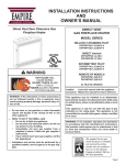
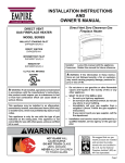
EMPIRE
Comfort Systems
INSTALLATION INSTRUCTIONS
AND
OWNER’S MANUAL
"B" Vent Zero Clearance Gas Fireplace
B-VENT
GAS FIREPLACE
MODEL SERIES
MILLIVOLT
BVD34FP30(F,L)N-2
BVD36FP3(0,2)(F,L)N-1
BVP42FP30(F,L)N-1
BVP42FP32(F,L)N-3
DIRECT IGNITION
GAS-FIRED
BVD34FP50(F,L)N-2
BVD36FP5(0,2)(F,L)N-1
BVP42FP50(F,L)N-1
BVP42FP52(F,L)N-3
UL FILE NO. MH45034
Installer: Leave these instructions with the consumer.
Consumer: Retain these instructions for future use.
WARNING: If the information in this manual is not
IROORZHGH[DFWO\D¿UHRUH[SORVLRQPD\UHVXOWFDXVLQJ
property damage, personal injury or loss of life.
- 'R QRW VWRUH RU XVH JDVROLQH RU RWKHU ÀDPPDEOH
vapors and liquids in the vicinity of this or any
other appliance.
- WHAT TO DO IF YOU SMELL GAS
Ɣ Do not try to light any appliance.
Ɣ Do not touch any electrical switch; do not use any
phone in your building.
Ɣ ,PPHGLDWHO\FDOO\RXUJDVVXSSOLHUIURPDQHLJKERUV
phone. Follow the gas supplier's instructions.
Ɣ ,I\RXFDQQRWUHDFK\RXUJDVVXSSOLHUFDOOWKH¿UH
department.
- Installation and service must be performed by
D TXDOL¿HG LQVWDOOHU VHUYLFH DJHQF\ RU WKH JDV
supplier.
NOT INTENDED FOR USE AS A PRIMARY HEAT
SOURCE. This appliance is tested and approved as
either supplemental room heat or as a decorative
appliance. It should not be factored as primary heat
in residential heating calculations.
This appliance is only for use with the type of gas
indicated on the rating plate. This appliance is not
FRQYHUWLEOHIRUXVHZLWKRWKHUJDVHVXQOHVVDFHUWL¿HG
kit is used.
WARNING: If not installed, operated and maintained
in accordance with the manufacturer’s instructions,
this product could expose you to substances in fuel or
from fuel combustion which can cause death or serious illness.
Page 1
TABLE OF CONTENTS
Section
Page
Important Safety Information....................................................................................................3
Safety Information for Users of LP Gas....................................................................................4
Introduction ..............................................................................................................................5
6SHFL¿FDWLRQV.............................................................................................................................6
Fireplace Dimensions ................................................................................................................6
Clearances .................................................................................................................................7
Locating Fireplace.....................................................................................................................7
Gas Supply .............................................................................................................................8-9
Installation .........................................................................................................................10-11
Venting................................................................................................................................12-13
Log Placement (BVD34 and BVD36) (5 Log Set) .................................................................14
Log Placement (BVP42) (4 Log Set) ......................................................................................15
Operating Instructions ........................................................................................................16-17
Standing Pilot Wiring Diagram ...............................................................................................18
Standing Pilot Lighting Instructions........................................................................................19
Standing Pilot Troubleshooting ...............................................................................................20
Standing Pilot Propane/LP Gas Conversion.......................................................................21-22
Direct Ignition Wiring Diagram ..............................................................................................23
Optional Remote Control (120V Direct Ignition) ...................................................................23
Direct Ignition Lighting Instructions.......................................................................................24
Direct Ignition Troubleshooting ..............................................................................................25
Direct Ignition Propane/LP Gas Conversion......................................................................25-26
Maintenance and Service.........................................................................................................27
BVD34 and BVD36 Parts List ................................................................................................28
BVD34 and BVD36 Parts View ..............................................................................................29
BVP42 Parts List .....................................................................................................................30
BVP42 Parts View...................................................................................................................31
FBB4 Optional Variable Speed Blower Installation Instructions.......................................32-33
Junction Box Wiring Installation Instructions.........................................................................34
Optional Accessories ...............................................................................................................35
Decorative Accessories............................................................................................................36
Master Parts Distributor List ...................................................................................................37
How To Order Repair Parts .....................................................................................................37
Quick Reference Guide ......................................................................................................38-39
Page 2
26534-1-0610
IMPORTANT SAFETY INFORMATION
Before enclosing the vent pipe assembly, operate the appliance to ensure it is venting properly.
,I WKLV DSSOLDQFH LV LQVWDOOHG GLUHFWO\ RQ FDUSHWLQJ
tile or other combustible material other than wood
ÀRRULQJWKHDSSOLDQFHVKDOOEHLQVWDOOHGRQDPHWDO
or wood panel extending the full width and depth of
the appliance.
7KHEDVHUHIHUUHGWRDERYHGRHVQRWPHDQWKH¿UHSURRI
base as used on wood stoves. The protection is for
rugs that are extremely thick and light colored tile.
&KLOGUHQDQGDGXOWVVKRXOGEHDOHUWHGWRWKHKD]DUGV
of high surface temperatures and should stay away
to avoid burns or clothing ignition.
<RXQJFKLOGUHQVKRXOGEHFDUHIXOO\VXSHUYLVHGZKHQ
they are in the same room as the appliance.
&ORWKLQJRURWKHUÀDPPDEOHPDWHULDOVKRXOGQRWEH
placed on or near the appliance.
$GHTXDWHDFFHVVLELOLW\FOHDUDQFHVIRUVHUYLFLQJDQG
proper operation.
7KLVDSSOLDQFHPXVWQRWVKDUHRUEHFRQQHFWHGWRDÀXH
serving a separate solid-fuel burning appliance.
.HHS WKH DUHD DURXQG \RXU DSSOLDQFH FOHDU RI
FRPEXVWLEOHPDWHULDOVJDVROLQHDQGRWKHUÀDPPDEOH
vapor and liquids.
8QGHU QR FLUFXPVWDQFHV VKRXOG DQ\ VROLG IXHOV
(wood, coal, paper or cardboard etc.) be used in this
appliance.
7KHÀRZRIFRPEXVWLRQDQGYHQWLODWLRQDLUPXVWQRW
be obstructed in any way.
'XHWRKLJKWHPSHUDWXUHVWKHDSSOLDQFHVKRXOGEH
ORFDWHGRXWRIWUDI¿FDQGDZD\IURPIXUQLWXUHDQG
draperies.
$Q\SDUWUHPRYHGIRUVHUYLFLQJWKHDSSOLDQFHPXVW
be replaced prior to operating the appliance. Work
VKRXOGEHGRQHE\DTXDOL¿HGVHUYLFHSHUVRQ
.HHSEXUQHUDQGFRQWUROFRPSDUWPHQWFOHDQ
9HQWFDSLVKRWZKLOH¿UHSODFHLVLQRSHUDWLRQ
Installation and repair should be done by a
48$/,),('6(59,&(3(5621The appliance
should be inspected before use and at least annually
by a qualified service person. More frequent
cleaning may be required due to excessive lint from
carpeting, bedding materials, etc. It is imperative
that control compartments, burners and circulating
air passageways of the appliance be kept clean.
'2127SXWDQ\WKLQJDURXQGWKH¿UHSODFHWKDWZLOO
REVWUXFWWKHÀRZRIYHQWLODWLRQDLU
26534-1-0610
&OHDUDQFHLQDFFRUGDQFHZLWKORFDOLQVWDOODWLRQFRGHV
and the requirements of the gas supplier.
'2 keep the appliance area clear and free from
FRPEXVWLEOHPDWHULDOJDVROLQHDQGRWKHUÀDPPDEOH
vapors and liquids.
'2 examine venting system periodically and replace
damaged parts.
'2make a periodic visual check of pilot and burners.
Clean and replace damaged parts.
'2127XVHWKLV¿UHSODFHLIDQ\SDUWKDVEHHQXQGHU
ZDWHU,PPHGLDWHO\FDOODTXDOL¿HGVHUYLFHWHFKQLFLDQ
to inspect the heater and to replace any part of the
control system and any gas control which has been
under water.
$Q\VDIHW\VFUHHQRUJXDUGUHPRYHGIRUVHUYLFLQJ
an appliance must be replaced prior to operating
the appliance.
Page 3
SAFETY INFORMATION FOR USERS OF LP GAS
3URSDQH/3*DVLVDÀDPPDEOHJDVZKLFKFDQFDXVH¿UHV
and explosions. In its natural state, propane is odorless and
colorless. You may not know all the following safety precautions which can protect both you and your family from an
accident. Read them carefully now, then review them point
by point with the members of your household. Someday when
there may not be a minute to lose, everyone’s safety will depend
on knowing exactly what to do. If, after reading the following
information, you feel you still need more information, please
contact your gas supplier.
LP-GAS WARNING ODOR
If a gas leak happens, you should be able to smell the gas because of the odorant put in the LP-Gas.
That’s your signal to go into immediate action!
'R QRW RSHUDWH HOHFWULF VZLWFKHV OLJKW PDWFKHV XVH \RXU
phone. Do not do anything that could ignite the gas.
*HWHYHU\RQHRXWRIWKHEXLOGLQJYHKLFOHWUDLOHURUDUHD'R
that IMMEDIATELY.
&ORVHDOOJDVWDQNRUF\OLQGHUVXSSO\YDOYHV
/3*DVLVKHDYLHUWKDQDLUDQGPD\VHWWOHLQORZDUHDVVXFK
as basements. When you have reason to suspect a gas leak,
keep out of basements and other low areas. Stay out until
¿UH¿JKWHUVGHFODUHWKHPWREHVDIH
8VH\RXUQHLJKERU¶VSKRQHDQGFDOODWUDLQHG/3*DVVHUYLFH
SHUVRQDQGWKH¿UHGHSDUWPHQW(YHQWKRXJK\RXPD\QRW
continue to smell gas, do not turn on the gas again. Do not
re-enter the building, vehicle, trailer, or area.
Finally,OHWWKHVHUYLFHPDQDQG¿UH¿JKWHUVFKHFNIRUHVFDSHG
gas. Have them air out the area before you return. Properly
trained LP-Gas service people should repair the leak, then
check and relight the gas appliance for you.
NO ODOR DETECTED - ODOR FADE
Some people cannot smell well. Some people cannot smell the
RGRURIWKHFKHPLFDOSXWLQWRWKHJDV<RXPXVW¿QGRXWLI\RX
can smell the odorant in propane. Smoking can decrease your
ability to smell. Being around an odor for a time can affect your
sensitivity or ability to detect that odor. Sometimes other odors
in the area mask the gas odor. People may not smell the gas odor
or their minds are on something else. Thinking about smelling a
gas odor can make it easier to smell.
The odorant in LP-Gas is colorless, and it can fade under some
circumstances. For example, if there is an underground leak, the
PRYHPHQWRIWKHJDVWKURXJKVRLOFDQ¿OWHUWKHRGRUDQW2GRUDQWV
in LP-Gas also are subject to oxidation. This fading can occur if
there is rust inside the storage tank or in iron gas pipes.
The odorant in escaped gas can adsorb or absorb onto or into walls,
masonry and other materials and fabrics in a room. That will take
some of the odorant out of the gas, reducing its odor intensity.
LP-Gas may stratify in a closed area, and the odor intensity could
vary at different levels. Since it is heavier than air, there may be
more odor at lower levels. Always be sensitive to the slightest gas
odor. If you detect any odor, treat it as a serious leak. Immediately
go into action as instructed earlier.
SOME POINTS TO REMEMBER
/HDUQWRUHFRJQL]HWKHRGRURI/3*DV Your local LP-Gas
'HDOHUFDQJLYH\RXD³6FUDWFKDQG6QLII´SDPSKOHW8VHLWWR¿QG
out what the propane odor smells like. If you suspect that your
LP-Gas has a weak or abnormal odor, call your LP-Gas Dealer.
,I \RX DUH QRW TXDOL¿HG GR QRW OLJKW SLORW OLJKWV SHUIRUP
service, or make adjustments to appliances on the LP-Gas system.
,I\RXDUHTXDOL¿HGFRQVFLRXVO\WKLQNDERXWWKHRGRURI/3*DV
prior to and while lighting pilot lights or performing service or
making adjustments.
6RPHWLPHV D EDVHPHQW RU D FORVHGXS KRXVH KDV D PXVW\
smell that can cover up the LP-Gas odor. Do not try to light pilot
lights, perform service, or make adjustments in an area where the
conditions are such that you may not detect the odor if there has
been a leak of LP-Gas.
2GRUIDGHGXHWRR[LGDWLRQE\UXVWRUDGVRUSWLRQRQZDOOV
of new cylinders and tanks, is possible. Therefore, people should
be particularly alert and careful when new tanks or cylinders are
placed in service. Odor fade can occur in new tanks, or reinstalled
ROG WDQNV LI WKH\ DUH ¿OOHG DQG DOORZHG Wo set too long before
Page 4
UH¿OOLQJ&\OLQGHUVDQGWDQNVZKLFKKDYHEHHQRXWRIVHUYLFHIRU
a time may develop internal rust which will cause odor fade. If
such conditions are suspected to exist, a periodic sniff test of the
gas is advisable. If you have any question about the gas odor,
call your LP-Gas dealer. A periodic sniff test of the LP-Gas is
a good safety measure under any condition.
,IDWDQ\WLPH\RXGRQRWVPHOOWKH/3*DVRGRUDQWDQG\RX
think you should, assume you have a leak. Then take the same
immediate action recommended above for the occasion when you
do detect the odorized LP-Gas.
,I \RX H[SHULHQFH D FRPSOHWH ³JDV RXW´ WKH FRQWDLQHU LV
under no vapor pressure), turn the tank valve off immediately. If
the container valve is left on, the container may draw in some air
WKURXJKRSHQLQJVVXFKDVSLORWOLJKWRUL¿FHV,IWKLVRFFXUVVRPH
new internal rusting could occur. If the valve is left open, then
treat the container as a new tank. Always be sure your container
is under vapor pressure by turning it off at the container before it
JRHVFRPSOHWHO\HPSW\RUKDYLQJLWUH¿OOHGEHIRUHLWLVFRPSOHWHO\
empty.
26534-1-0610
INTRODUCTION
Instructions to Installer
1. Installer must leave instruction manual with owner after
installation.
,QVWDOOHUPXVWKDYHRZQHU¿OORXWDQGPDLOZDUUDQW\FDUGVXSSOLHG
ZLWKWKH¿UHSODFH
3. Installer should show owner how to start and operate the
¿UHSODFH
This is a B-Vent gas appliance and must be installed with a listed BVent vent system. The information contained in this manual pertains
to all models and gas control systems unless otherwise noted.
Warning: This unit is not for use with solid fuels.
$SSOLDQFH&HUWL¿FDWLRQ
7KLV ¿UHSODFH LV GHVLJQ FHUWL¿HG LQ DFFRUGDQFH ZLWK $PHULFDQ
National Standard/CSA Standard ANSI Z.21-50/CSA 2.22 and by
Underwriters Laboratories as a Vented Gas Appliance and shall be
installed according to these instructions.
Consult your local building code agency, prior to installation,
to ensure compliance with local codes-including permits and
inspections.
7KH ¿UHSODFH ZKHQ LQVWDOOHG PXVW EH HOHFWULFDOO\ JURXQGHG LQ
accordance with local codes or, in absence of local codes, with
the National Electric Code ANSI/NFPA 70 if an external electrical
source is utilized.
These models may be installed in a bedroom or bed-sitting room
in the U.S.A.
4XDOL¿HG,QVWDOOLQJ$JHQF\
,QVWDOODWLRQDQGUHSODFHPHQWRIJDVSLSLQJJDVXWLOL]DWLRQHTXLSPHQW
RU DFFHVVRULHV DQG UHSDLU DQG VHUYLFLQJ RI HTXLSPHQW VKDOO EH
SHUIRUPHGRQO\E\DTXDOL¿HGDJHQF\7KHWHUP³TXDOL¿HGDJHQF\´
PHDQVDQ\LQGLYLGXDO¿UPFRUSRUDWLRQRUFRPSDQ\ZKLFKHLWKHULQ
person or through a representative is engaged in and is responsible
for (a) the installation or replacement of gas piping or (b) the
FRQQHFWLRQLQVWDOODWLRQUHSDLURUVHUYLFLQJRIHTXLSPHQWZKRLV
H[SHULHQFHGLQVXFKZRUNIDPLOLDUZLWKDOOSUHFDXWLRQVUHTXLUHG
DQGKDVFRPSOLHGZLWKDOOWKHUHTXLUHPHQWVRIWKHDXWKRULW\KDYLQJ
jurisdiction.
State of Massachusetts: The installation must be made
E\ D OLFHQVHG SOXPEHU RU JDV ¿WWHU LQ WKH &RPPRQZHDOWK RI
0DVVDFKXVHWWV 7KH VWDWH RI 0DVVDFKXVHWWV UHTXLUHV WKDW D
ÀH[LEOHDSSOLDQFHFRQQHFWRUFDQQRWH[FHHGWKUHHIHHWLQOHQJWK
The installation must conform with local codes or, in the absence of
local codes, with the National Fuel Gas Code ANSI Z223.1/NFPA
54* Natural Gas and Propane Installation Code, or CSA B149.1
in Canada. *Available from the American National Standards Institute, Inc. 11
West 42nd St., New York, N.Y. 10036.
Warning: ANY CHANGE TO THIS FIREPLACE OR ITS
CONTROLS CAN BE DANGEROUS.
,PSURSHULQVWDOODWLRQRUXVHRIWKH¿UHSODFHFDQFDXVHVHULRXV
LQMXU\RUGHDWKIURP¿UHEXUQVH[SORVLRQVRUFDUERQPRQR[LGH
poisoning.
Any alteration of the original design, installed other than as
26534-1-0610
shown in these instructions or use with a type of gas not shown on
the rating plate is the responsibility of the person and company
making the change.
Important
All correspondence should refer to complete Model Number, Serial
Number and type of gas.
High Altitude
When installing this unit at an elevation above 2000 feet (in the
United States) it may be necessary to decrease the input rating by
FKDQJLQJWKHH[LVWLQJEXUQHURUL¿FHWRDVPDOOHUVL]H*HQHUDOO\
input should be reduced 4 percent for each 1000 feet above sea
level. However, if the heating value of the gas has been reduced,
this general rule may not apply. Check with local gas utility for
SURSHURUL¿FHVL]HLGHQWL¿FDWLRQ
Canadian High Altitude
Altitude: 0-4500 feet (0-1370 m)
When installing this unit at an elevation above 4500 feet (in Canada),
check with local authorities.
Consult your local gas utility for assistance in determining the
SURSHURUL¿FHIRUORFDWLRQ
Preparation
7KLV JDV ¿UHSODFH DQG LWV FRPSRQHQWV DUH WHVWHG DQG VDIH ZKHQ
installed in accordance with this Installation Manual. Report to
\RXU GHDOHU DQ\ SDUWV GDPDJHG LQ VKLSPHQW VSHFL¿FDOO\ FKHFN
glass condition. Do not install unit with damaged, incomplete, or
substitute parts. Read all instructions before starting installation
and follow these instructions carefully during installation to insure
PD[LPXPEHQH¿WDQGVDIHW\)DLOXUHWRIROORZWKHPZLOOYRLG\RXU
ZDUUDQW\DQGPD\SUHVHQWD¿UHKD]DUG
The warranty will be voided by, and the warrantor disclaims any
responsibility for the following actions:
,QVWDOODWLRQ RI DQ\ GDPDJHG ILUHSODFH RU YHQW V\VWHP
component.
0RGL¿FDWLRQRIWKH¿UHSODFHRUYHQWV\VWHP
,QVWDOODWLRQRWKHUWKDQDVLQVWUXFWHGE\(PSLUH&RPIRUW6\VWHPV
Inc.
,PSURSHUSRVLWLRQLQJRIWKHORJVJODVVGRRURSWLRQDODFFHVVRULHV
or decorative rock.
,QVWDOODWLRQDQGRUXVHRIDQ\FRPSRQHQWSDUWQRWPDQXIDFWXUHG
or approved by manufacturer.
*ODVV6SHFL¿FDWLRQV
Optional glass door kits manufactured with tempered glass
may be installed in hazardous locations such as bathtub
HQFORVXUHVDVGH¿QHGE\WKH&RQVXPHU3URGXFW6DIHW\&RPPLVVLRQ
&36&7KHWHPSHUHGJODVVKDVEHHQWHVWHGDQGFHUWL¿HGWRWKH
UHTXLUHPHQWV RI ANSI Z97.1 and CPSC 16 CFR 1202
6DIHW\ *OD]LQJ &HUWL¿FDWLRQ &RXQFLO SGCC# 1595 and 1597.
Architectural Testing, Inc. Reports 02-31919.01 and
02-31917.01).
This statement is in compliance with CPSC 16 CFR Section
1201.5 &HUWL¿FDWLRQ DQG ODEHOLQJ UHTXLUHPHQWV ZKLFK UHIHUV
to 15 U.S. Code (USC) 2063 VWDWLQJ 6XFK FHUWL¿FDWH VKDOO
accompany the product or shall otherwise be furnished to any distributor or retailer to whom the product is delivered."
Page 5
SPECIFICATIONS
Input Btu/hr Maximum
KWH (Maximum)
B-Vent Size
NAT. (Standard)
2UL¿FH
Air Shutter Opening
/3&RQYHUVLRQ.LW5HTXLUHG
2UL¿FH
Air Shutter Opening
Height without standoff
Width
Depth
Gas Inlet Shutoff Valve (Pipe)
BVD34FP
21,000
6.2
4" Diameter
BVD36FP
25,000
7.3
6" Diameter
BVP42FP
30,000
8.8
6" Diameter
#44 (.086)
P-252
1/8" (3.2mm)
#42 (.0935)
P-286
1/8"(3.2mm)
#37 (.104)
P-213
1/8" (3.2mm)
1.35mm
P-289
5/16" (7.9mm)
32 3/4"(832mm)
37" (940mm)
14 7/8" (378mm)
1/2 NPT
1.45 mm
P-208
5/16" (7.9mm)
34 3/4"(883mm)
39" (990mm)
18 3/8" (467mm)
1/2 NPT
1.65mm
P-250
Full Open
34 3/4"(883mm)
43" (1,092mm)
18 3/8" (467mm)
1/2NPT
NOTE: Air shutter
settings are factory
minimum settings. Some
venting configurations
PD\ UHTXLUH PLQRU DLU
shutter adjustments for
optimum performance.
*NOTE:/3&RQYHUVLRQNLWVDUHLQFOXGHGRQWKHYGLUHFWLJQLWLRQPRGHO¿UHSODFHV)RUPLOOLYROWPRGHOVXVHNLW
#19160 for BVD34FP Series, kit #19161 for BVD36FP Series, and kit #19162 for BVP42FP Series.
Remote Control Options &
Accessories
FRBC
FREC
FWS-1
Description
MILLIVOLT BATTERY REMOTE ON/OFF
DIRECT IGNITION/MILLIVOLT 120V ON/OFF REMOTE
DIRECT IGNITION/MILLIVOLT WALL SWITCH
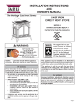
FIREPLACE DIMENSIONS
Dim
A
B
C
D
E
F
G
H
I
J
K
L
M
N
O
Figure 1
Page 6
P
%9'
37"
940mm
34"
864 mm
22 7/8"
581mm
35 5/8"
905 mm
32 3/4"
832mm
14 7/8"
378mm
6 3/8"
162mm
5 7/8"
149mm
24 1/2"
622mm
12 1/4"
311mm
1 1/4"
32mm
31 3/4"
807mm
32 11/16"
830mm
2 1/16"
53mm
5 5/8"
143mm
4 7/8"
124mm
%9'
39"
990mm
36"
914mm
24 7/8"
632mm
37 5/8"
956 mm
34 3/4"
883 mm
18 3/8
467mm
6 3/8"
162mm
8 3/8"
213mm
22 1/2"
572mm
11 1/4"
286mm
1 1/4"
32mm
33 3/4"
857mm
34 11/16"
881mm
2 1/16"
53mm
5 5/8"
143mm
4 7/8"
124mm
%93
43"
1092mm
40"
1,016mm
24 7/8"
632mm
37 5/8"
956 mm
34 3/4"
883 mm
18 3/8"
467mm
6 3/8"
162mm
6 3/8"
162mm
26 1/2"
673mm
13 1/4"
337mm
1 1/4"
32mm
33 3/4"
857mm
34 11/16"
881mm
2 1/16"
53mm
5 5/8"
143mm
4 7/8"
124mm
26534-1-0610
CLEARANCES
Mantel Chart (Figure 3)
Clearance to Combustibles
Back
0" (0 mm)
Side
0" (0 mm)
Floor
0" (0 mm)
Top Stand-off
0" (0 mm)
Top Framing Edge
1" (25mm)
Figure 3
&OHDUDQFHV)LJXUH
&OHDUDQFHIURPWRSIURQWHGJHRI¿UHSODFHWRFHLOLQJLV
&OHDUDQFHIURPVLGHRI¿UHSODFHWRDGMDFHQWVLGHZDOOLV
Figure 2
Combustible Material
No greeting cards, stockings or ornamentation of any type should
EH SODFHG RQ RU DWWDFKHG WR WKH ¿UHSODFH 7KH ÀRZ RI KHDW FDQ
ignite combustibles.
)LJXUH
LOCATING FIREPLACE
Note: When you install your
Fireplace on wall corner
positions, a minimum of 6 inches
clearance must be maintained
from the perpendicular side wall
and the screened opening of the
appliance.
Figure 5
26534-1-0610
Page 7
GAS SUPPLY
The gas pipeline can be brought in through the right or left side of
the appliance. Consult the current National Fuel Gas Code, ANSI
Z223.1 CAN/CGA-B149 (.1 or .2) installation code.
Recommended Gas Pipe Diameter
Pipe Length
(Feet)
Schedule 40 Pipe
Inside Diameter
Tubing, Type L
Outside Diameter
Nat.
L.P.
Nat.
L.P.
0-10
1/2"
12.7mm
3/8"
9.5mm
1/2"
12.7mm
3/8"
9.5mm
11-40
1/2"
12.7mm
1/2"
12.7mm
5/8"
15.9mm
1/2"
12.7mm
41-100
1/2"
12.7mm
1/2"
12.7mm
3/4"
19mm
1/2"
12.7mm
101-150
3/4"
19mm
1/2"
12.7mm
7/8"
22.2mm
3/4"
1.9 mm
Note:1HYHUXVHSODVWLFSLSH&KHFNWRFRQ¿UPZKHWKHU\RXUORFDO
codes allow copper tubing or galvanized.
Note: Since some municipalities have additional local codes, it is
always best to consult your local authority and installation code.
The use of the following gas connectors is recommended:
— ANS Z21.24 Appliance Connectors of Corrugated Metal Tubing
and Fittings.
— ANS Z21.45 Assembled Flexible Appliance Connectors of
Other Than All-Metal Construction
The above connectors may be used if acceptable by the authority
KDYLQJMXULVGLFWLRQ7KHVWDWHRI0DVVDFKXVHWWVUHTXLUHVWKDWDÀH[LEOH
appliance connector cannot exceed three feet in length.
Installing a New Main Gas Cock
Each appliance should have its own manual gas cock.
A manual main gas cock should be located in the vicinity of
the unit. Where none exists, or where its size or location is not
DGHTXDWH FRQWDFW \RXU ORFDO DXWKRUL]HG LQVWDOOHU IRU LQVWDOODWLRQ
or relocation.
Compounds used on threaded joints of gas piping shall be resistant
WRWKHDFWLRQRIOLTXH¿HGSHWUROHXPJDVHV7KHJDVOLQHVPXVWEH
checked for leaks by the installer. This should be done with a soap
solution watching for bubbles on all exposed connections, and if
unexposed, a pressure test should be made.
1HYHUXVHDQH[SRVHGÀDPHWRFKHFNIRUOHDNV$SSOLDQFHPXVW
be disconnected from piping at inlet of control valve and pipe
capped or plugged for pressure test. Never pressure test with
appliance connected; control valve will sustain damage!
NOTE: 7KHPLOOLYROWJDVFRQWUROVDUHHTXLSSHGZLWKDFDSWXUHG
screw type pressure test point, therefore it is not necessary to provide
a 1/8" test point up stream of the control.
2QGLUHFWLJQLWLRQYDOYHVKH[SOXJVPD\EHUHSODFHGZLWKKRVH¿WWLQJV
IRUSUHVVXUHFKHFNVWKHQUHLQVWDOOHGEHIRUHRSHUDWLQJ¿UHSODFH
:KHQXVLQJFRSSHURUÀH[FRQQHFWRUXVHRQO\DSSURYHG¿WWLQJV
The appliance and it’s individual shut off valve must be disconnected
from supply piping system during any pressure testing of that system
at test pressures in excess of 1/2 psig (3.5kPa).
The appliance must be isolated from the gas supply piping system
by closing its individual manual shut off valve during any pressure
WHVWLQJRIWKHJDVVXSSO\SLSLQJV\VWHPDWWHVWSUHVVXUHVHTXDOWRRU
less than 1/2 psig (3.5kPa).
Attention! If one of the procedures results in pressures in excess
RISVLJZFN3DRQWKH¿UHSODFHJDVYDOYHLWZLOO
result in a hazardous condition.
Figure 6
Gas Supply Pressure (inches w.c.)
Minimum
Normal
Maximum
Natural Gas
4.5"
7.0"
14.0"
LP (Propane)
10.8"
11.0"
14.0"
Manifold Pressure (inches w.c.)
Normal (HI)
Natural Gas
3.5"
LP (Propane)
10.0"
Page 8
26534-1-0610
GAS SUPPLY (CONT)
Checking Manifold Pressures
Both Propane and Natural gas valves have a built-in pressure
regulator in the gas valve. Natural gas models will have a manifold
pressure of approximately 3.5" w.c. (.871kPa) at the valve outlet
with the inlet pressure to the valve from a minimum of 4.5" w.c.
(1.120kPa) for the purpose of input adjustment to a maximum of
14.0" w.c. (3.484kPa). Propane gas models will have a manifold
pressure approximately 10.0" w.c. (2.49kPa) at the valve outlet
with the inlet pressure to the valve from a minimum of 10.8" w.c.
(2.68kPa) for the purpose of input adjustment to a maximum of
14.0" w.c. (3.484kPa).
Figure 7
Figure 8
26534-1-0610
Page 9
INSTALLATION
Framing and Finishing
1. Choose unit location.
)UDPHLQ¿UHSODFHZLWKDKHDGHUDFURVVWKHWRS,WLVLPSRUWDQW
WRDOORZIRUWKH¿QLVKHGIDFHWKLFNQHVVZKHQVHWWLQJWKHGHSWK
of the frame. See Figures 9 & 11.
$WWDFK¿UHSODFHWRIUDPLQJXVLQJDGMXVWDEOHQDLOLQJÀDQJHV
Preset depth to suit facing material (adjustable to 1/2", 5/8" or
3/4" depths).
4. Use (8) 1/2" hex-head screws supplied in hardware package to
VFUHZWKURXJKVORWWHGKROHVLQQDLOLQJÀDQJHVWKHQVFUHZLQWR
SUHGULOOHGKROHVRQ¿UHSODFHVLGH0HDVXUHIURPIDFHRI¿UHSODFH
WRIDFHRIWKHQDLOLQJÀDQJHVWRGHWHUPLQH¿QDOGHSWK
,QVWDOOWKH)UHVK$LU.LW%9$
A fresh air kit is available as an optional feature with this appliance.
The fresh air kit helps to decrease the amount of room air taken by
utilizing outside air for combustion. It is strongly recommended that
it be installed. Installation of the fresh air kit should be performed
DWWKHIUDPLQJVWDJHRIWKH¿UHSODFHLQVWDOODWLRQ
7KHIUHVKDLUNLWLQVWDOOVRQWKHOHIWVLGHRIWKH¿UHSODFH
To install the BVA1 fresh air kit, refer to the installation instructions
provided with the kit.
Note: The outside air kit can terminate at any level with the
exception that it must terminate at least 1 ft below the vent
termination cap. The fresh air kit inlet hood should be positioned
at least 2 ft above the ground level, in a manner that will not
allow snow, leaves, etc. to block the inlet.
WARNING: Exhaust products of gasoline engines are
KD]DUGRXV7KHRXWVLGHDLUPXVWQRWEHWDNHQIURPDJDUDJH
VSDFHDWWLFVSDFHVEDVHPHQWVRUDERYHWKHURR¿QJZKHUH
RWKHUKHDWLQJDSSOLDQFHIDQVRUFKLPQH\VH[KDXVWRUXWLOL]H
the air.
Framing (Figure 11)
)LUHSODFHIUDPLQJFDQEHEXLOWEHIRUHRUDIWHUWKH¿UHSODFHLVVHWLQ
place. Framing should be positioned to accommodate wall covering
DQG ¿UHSODFH IDFLQJ PDWHULDO 7KH ¿UHSODFH IUDPLQJ VKRXOG EH
constructed of 2 x 4 lumber or heavier. The framing headers may
UHVWRQWKH¿UHSODFHVWDQGRIIV5HIHUWR)LJXUHIRUPLQLPXP
framing dimensions.
CAUTION: MEASURE FIREPLACE DIMENSIONS AND
9(5,)<)5$0,1*0(7+2'6$1':$//&29(5,1*
DETAILS BEFORE FRAMING CONSTRUCTION
BEGINS.
Figure 9
9HQW3LSH&OHDUDQFH
Note: Maintain one inch (1") of clearance around vertical vent pipe.
)ROORZWKH%9HQWV\VWHPLQVWUXFWLRQVIRULQVWDOODWLRQUHTXLUHPHQWV
and clearances. Failure to follow the B-Vent manufacturer's
LQVWUXFWLRQVPD\FDXVHLPSURSHUGUDIWDQGSRVVLEOH¿UHKD]DUG
Framing dimension "A" includes a three inch clearance for
VWDQGRIIVRQ¿UHER[
Figure 10
Page 10
26534-1-0610
INSTALLATION (CONT)
Combustible Surround Installation
Minimum Framing Dimensions
BVD34
BVD36
BVP42
"A"
35 3/4"
(908mm)
37 3/4"
(959mm)
37 3/4"
(959mm)
"B"
37 3/8"
(949mm)
39 3/8"
(1,000mm)
43 3/8"
(1,102mm)
"C"
14 3/8"
(378mm)
17 7/8"
(454mm)
17 7/8"
(454mm)
Note: 'LPHQVLRQ&LVWKHPLQLPXPZLWKWKH¿UHSODFHIDFHH[WHQGLQJLQIURQW
RIWKHIUDPLQJWRDOORZIRU¿QLVKLQJPDWHULDOV
Figure 11
Attention: $GG WR ³$´ GLPHQVLRQV ZKHQ XVLQJ D ÀXVK
mantel base.
Attention: If a base or mantel is not used and the appliance is
installed directly on carpeting, tile or other combustible material
RWKHUWKDQZRRGÀRRULQJLWVKDOOEHLQVWDOOHGRQDPHWDORUZRRG
panel extending the full width and depth of the appliance. The
vertical dimension in Figure 11 must be adjusted when a metal or
wood panel is placed beneath the appliance.
Louvered Models
Figure 12a
Finishing (Figure 12)
Finish the walls with the material of your choice. Only nonFRPEXVWLEOH PDWHULDOV PD\ EH XVHG WR FRYHU WKH EODFN ¿UHSODFH
front.
:DUQLQJ :KHQ ¿QLVKLQJ WKH ¿UHSODFH QHYHU REVWUXFW
or modify the air inlet/outlet louvers in any manner.
Provide adequate clearances around air openings into the
combustion chamber.
Caution: ,IWKHMRLQWVEHWZHHQWKH¿QLVKHGZDOODQGWKH¿UHSODFH
surround (top and sides) are sealed, a 300°F minimum sealant
PDWHULDOPXVWEHXVHG7KHVHMRLQWVDUHQRWUHTXLUHGWREHVHDOHG
Only non-combustible material (using 300°F minimum adhesive if
QHHGHGFDQEHDSSOLHGDVIDFLQJWRWKH¿UHSODFHVXUURXQG
26534-1-0610
Flush Face Models
Figure 12b
Attention: Cold climate installation recommendation:
When installing this unit against a non-insulated exterior
wall, it is recommended that the outer walls be insulated
to conform to applicable insulation codes.
Page 11
VENTING
9HQW5XQV
,QSODQQLQJWKHLQVWDOODWLRQIRUWKH¿UHSODFHLWLVQHFHVVDU\WRLQVWDOO
certain components before the appliance is completely positioned
and installed. These include the vent system, gas piping for the
appliance, Fresh Air Kit, and the electrical wiring. (The fan option
is available for louvered models only. Electric ignition models will
UHTXLUHHOHFWULFDOVHUYLFHWRMXQFWLRQER[
The appliance can be mounted on any of the following surfaces:
$ÀDWKDUGFRPEXVWLEOHEXUQDEOHVXUIDFH
2. A raised wooden platform.
3. Four (4) corner supports. (Example: Four (4) concrete masonry
blocks.) These supports must be positioned so they contact all
four (4) perimeter edges on the bottom of the unit.
Locate and mark the center point of the vent pipe using a nail on
the underside of the roof. Drive the nail through the center point.
Mark the outline of the roof hole around this center point.
NOTE: Size of the roof hole dimensions depend on the pitch of
the roof. There must be a 1 inch clearance (25mm) to the
vertical pipe sections. This clearance is to all combustible
material.
Cover the opening of the vent pipe and cut and frame the roof hole.
Use framing lumber the same size as the roof rafters and install the
frame securely. Flashing anchored to frame must withstand high
winds. The storm collar is placed over this joint to make a watertight seal. Non-hardening sealant should be used to completely seal
WKLVÀDVKLQJLQVWDOODWLRQ
'HWHUPLQLQJ0LQLPXP9HQW+HLJKW$ERYHWKH5RRI
WARNING: Major U.S. building codes specify minimum
chimney and/or vent height above the roof top. These
minimum heights are necessary in the interest of safety. These
VSHFL¿FDWLRQVDUHVXPPDUL]HGLQ)LJXUHVDQG.
Note that for steep roof pitches, the vent height must be increased.
In high wind conditions, nearby trees, adjoining roof lines, steep
pitched roofs, and other similar factors can result in poor draft,
or down-drafting. In these cases, increasing the vent height may
solve this problem.
General Maintenance
Conduct an inspection of the venting system semi-annually.
Recommended areas to inspect are as follows:
1. Check areas of the venting system which are exposed to the
elements for corrosion. These will appear as rust spots or
streaks and, in extreme cases, holes. These components should
immediately be replaced.
5HPRYHWKHFDSDQGVKLQHDÀDVKOLJKWGRZQWKHYHQW5HPRYH
any bird nests or other foreign material.
3. Check for evidence of excessive condensate, such as water
GURSOHWVIRUPLQJLQWKHLQQHUOLQHUDQGVXEVHTXHQWO\GULSSLQJ
out at joints. Condensate can cause corrosion of caps, pipe and
¿WWLQJV,WPD\EHFDXVHGE\KDYLQJH[FHVVLYHODWHUDOUXQVWRR
many elbows and exterior portions of the system being exposed
to cold weather.
,QVSHFWMRLQWVWRYHULI\WKDWQRSLSHVHFWLRQVRU¿WWLQJVKDYHEHHQ
GLVWXUEHGDQGFRQVHTXHQWO\ORRVHQHG$OVRFKHFNPHFKDQLFDO
supports, such as wall straps or plumbers’ tape for rigidity.
A removable panel or other means must be provided in the enclosure
IRUYLVXDOLQVSHFWLRQRIWKHÀXHFRQQHFWLRQ
NOTE: This also pertains to vertical vent systems installed on the
outside of the building.
,QVWDOOLQJWKH9HQW6\VWHPLQD&KDVH
A chase is a vertical box-like structure built to enclose the gas
appliance and/or it’s vent system. Vertical vent runs on the outside
RIDEXLOGLQJPD\EHEXWDUHQRWUHTXLUHGWREHLQVWDOOHGLQVLGHD
chase.
&$87,217UHDWPHQWRI¿UHVWRSVSDFHUVDQGFRQVWUXFWLRQRI
the chase may vary with the type of building. These instructions
are not substitutes for the requirements of local building
codes. Therefore, your local building codes must be checked
to determine the requirements for these steps.
ROOF PITCH
H (Min.)
Flat to 6/12
12" (305 mm)
6/12 to 7/12
15" (381 mm)
Over 7/12 to 8/12
18" (457 mm)
Over 8/12 to 16/12
24" (610 mm)
Over 16/12 to 21/12
36" (914 mm)
NOTE: When installing this vent system in a chase, it is always
good building practice to insulate the chase as you would the
outside walls of your home. This is especially important for cold
climate installations. Upon completion of building your chase
framing, install the vent system by following the instructions in
this manual. Remember to build the chase large enough so that
minimum clearance of combustible materials (including insulation)
to the vent system are maintained.
WARNING! This appliance must not be connected to a
FKLPQH\ ÀXH VHUYLFLQJ D VHSDUDWH VROLG IXHO RU JDV IXHO
burning appliance.
Figure 13
Page 12
26534-1-0610
VENTING (CONT)
9HQW6L]H
Model BVD34FP series uses a 4" B-Vent for operation.
Models BVD36FP and BVP42FP series use a 6" B-Vent for
operation.
1HYHUGRZQVL]HYHQWLQJGLDPHWHUV
2IIVHW9HQWLQJ:LWK(OERZV
Clearances
9HQWFOHDUDQFHVDUHSHUYHQWPDQXIDFWXUHU
VVSHFL¿FDWLRQV
9HQW&RQ¿JXUDWLRQ
9DULRXV YHQWLQJ FRQ¿JXUDWLRQV DUH VKRZQ LQ )LJXUHV DQG from which maximum vent runs can be determined.
:$51,1*5,6.2)),5(
Always maintain minimum clearances or greater around
the vent system. Do not pack air spaces with insulation or
other material.
Figure 15
9HUWLFDO9HQWLQJ1R(OERZV
)LJXUH
26534-1-0610
Page 13
LOG PLACEMENT (5 LOG SET)
Before you begin: if you are installing logs into the BVD34 or
%9' PRGHO WKHQ WKLV ¿UHSODFH LV VXSSOLHG ZLWK D VHW RI ¿YH
FHUDPLF¿EHUORJV'RQRWKDQGOHWKHVHORJVZLWK\RXUEDUHKDQGV
$OZD\VZHDUJORYHVWRSUHYHQWVNLQLUULWDWLRQIURPFHUDPLF¿EHUV
After handling logs, wash your hands gently with soap and water
WRUHPRYHDQ\WUDFHVRI¿EHUV
The positioning of the logs is critical to the safe and clean operation
RIWKLV¿UHSODFH6RRWLQJDQGRWKHUSUREOHPVPD\UHVXOWLIWKHORJV
DUHQRWSURSHUO\DQG¿UPO\SRVLWLRQHGLQWKH¿UHSODFH3OHDVHUHIHU
to Figure 16 and Figure 17 and corresponding WARNING when
completing following log placement instructions.
3ODFHIURQWORJVDQGEHWZHHQIURQWJUDWHÀDQJHDQG
main burner. Align notches on front logs with locator tabs in
base.
2. Place middle log (#3) between front and rear loop of burner.
Note: Do not place log on top of pilot assembly.
3ODFHUHDUORJRQUHDUORJVKHOI%RWWRPÀDQJHRIORJPXVW
be placed between the log shelf and burner tube.
3ODFHEUDQFKRQWRORJDQGÀDWDUHDRQORJ7KH
bottom of the branch is to be placed behind the grate tang that
is second from the left.
5. Place decorative rock in front of grates and sides of main burner
pan.
ATTENTION: Do not place decorative rock on logs or burner.
7KH GHFRUDWLYH URFN VKRXOG RQO\ EH SODFHG RQ WKH ¿UHSODFH
ÀRRU
5
4
3
2
1
Figure 16
WARNING: Failure to position the parts in accordance
ZLWK WKLV GLDJUDP RU IDLOXUH WR XVH RQO\ SDUWV VSHFL¿FDOO\
approved with this appliance may result in property
damage or personal injury.
Attention: Do not use Figure 16 or Figure 17 to order logs. Refer
to parts list on page 28 and parts view on page 29 to order logs
DQGRUHPEHUPDWHULDOIRU\RXUDSSURSULDWH¿UHSODFHPRGHO
EMBER MATERIAL PLACEMENT ON BURNER
6. After all logs are positioned properly, apply Rockwool ember
material to the front burner port area. To apply, carefully
separate the ember material into small amounts no larger than
"dime size" pieces. Fluffed up pieces one layer thick on top
of the burner generally works best, and will provide the best
ember glow. Do not place ember material more than one layer
thick. No more than (1) small packet of ember material (part
no. 15999) evenly placed on the burner, is recommended on
BVD34 and BVD36 models. Using additional ember material
will decrease the amount of ember glow effect. Extra ember
material should be saved for future ember applications as
necessary. See Figure 17.
Optional Platinum Bright Ember Kits are available from your
Fireplace Dealer. These embers may be used with all BVD/BVP
6HULHV¿UHSODFHV2UGHUDQGXVHDVLQGLFDWHGDVEHORZ
Platinum Bright Embers
PE-20-1
Figure 17
Note: A signle layer of embers is to be used when applying Platinum
Bright Embers (alone or in combination with production embers)
to the burner.
Page 14
26534-1-0610
/2*3/$&(0(17/2*6(7
%HIRUH\RXEHJLQ7KLV¿UHSODFHLVVXSSOLHGZLWKDVHWRIWKUHH
FHUDPLF¿EHUORJV'RQRWKDQGOHWKHVHORJVZLWK\RXUEDUHKDQGV
$OZD\VZHDUJORYHVWRSUHYHQWVNLQLUULWDWLRQIURPFHUDPLF¿EHUV
After handling logs, wash your hands gently with soap and water
WRUHPRYHDQ\WUDFHVRI¿EHU
The positioning of logs is critical to safe and clean operation of
WKLV¿UHSODFH6RRWLQJDQGRWKHUSUREOHPVPD\UHVXOWLIWKHORJV
DUHQRWSURSHUO\DQG¿UPO\SRVLWLRQHGLQWKH¿UHSODFH3OHDVH
refer to Figure 18, Figure 19, and Figure 20 and corresponding
WARNING, when completing the following log placement
steps.
1. Remove top louver, grasp louver, lift and pull forward.
2. Lower bottom louver, lift and hinge forward.
3. Release two glass frame spring clamps at bottom of
¿UHER[
4. Place rear (#1) log onto two (2) pins on rear log support.
5. Place left, front (#2) log onto two (2) left, front pins on burner
pan.
6. Place right, front (#3) log onto two (2) right, front pins on
burner pan.
7. Place Branch (#4) onto one (1) pin on rear log
8. Place decorative rock in front of grates and sides of main
burner.
Figure 19
WARNING: Failure to position the parts in accordance
ZLWK WKLV GLDJUDP RU IDLOXUH WR XVH RQO\ SDUWV VSHFL¿FDOO\
approved with this appliance may result in property damage
or personal injury.
Attention: Do not use Figure 61 or Figure 62 to order logs. Refer
to parts view on page 57 and parts list on pages 58 and 59 to
RUGHUORJVDQGRUHPEHUPDWHULDOIRU\RXUDSSURSULDWH¿UHSODFH
model.
ATTENTION: Do not place decorative rock on logs or on
burner. The decorative rock should only be placed on the
¿UHSODFHÀRRU
9. After all logs are properly positioned, place small "dime"
size pieces of Rockwool lightly across the front round
EOXHÀDPH SRUWV 3ODFH WKH HPEHU PDWHULDO 5RFNZRRO
pieces) side by side. Do not stack more than one layer of
embers across the burner ports. See Figure 18.
10.5HSODFHJODVVGRRURQWR¿UHER[
11. Secure the two glass frame spring clamps at bottom of
¿UHER[
12. Align the tabs on top louver brackets with slots in front posts
to secure top louver.
13. Close bottom louver. Lift slightly to engage the end tabs into
WKHVORWVLQ¿UHSODFHVLGHVWRFORVHORXYHUSDQHO
Figure 20
Figure 18
26534-1-0610
Page 15
OPERATING INSTRUCTIONS
750 Millivolt System
The standing pilot (750 millivolt system) is a continuous burning
pilot. The pilot remains ON even when the main burner is OFF.
The OWNER should carefully read and follow these operating
instructions at all times. Lower the door assembly to view the gas
FRQWUROVIRUWKH¿UHSODFH
When you ignite the pilot, the thermopile produces millivolts
(electrical current) which energizes the magnet in the gas valve.
After 30 seconds to 1 minute time period you can release the gas
FRQWURONQREDQGWKHSLORWZLOOVWD\21$OORZ\RXUSLORWÀDPHWR
operate an additional one (1) to two (2) minutes before you turn the
gas control knob from the PILOT position to the ON position. This
time period allows the millivolts (electrical current) to build-up to
DVXI¿FLHQWOHYHODOORZLQJWKHJDVFRQWUROWRRSHUDWHSURSHUO\
Initial Lighting
Upon completing the gas line or turning the gas valve on after it
has been in the “OFF” position, a small amount of air will be in the
OLQHV:KHQ¿UVWOLJKWLQJWKH¿UHSODFHLWZLOOWDNHDIHZPLQXWHV
for the lines to purge themselves of this air. Once the purging is
FRPSOHWHWKH¿UHSODFHZLOOOLJKWDQGRSHUDWHVDWLVIDFWRULO\
1. Follow the SAFETY and LIGHTING INSTRUCTIONS for
standing pilot controls found in this manual and on labels found
in control compartment behind the door assembly.
CAUTION: During the initial purging and subsequent lightings,
never allow the gas valve control knob to remain depressed in
WKH³SLORW´SRVLWLRQZLWKRXWSXVKLQJWKHSLH]RLJQLWRUEXWWRQ
at least once every second.
6XEVHTXHQWOLJKWLQJVRIWKHDSSOLDQFHZLOOQRWUHTXLUHVXFKSXUJLQJ
if the gas valve is not turned to “OFF.”
Pilot Flame (Figure 22)
The thermopile (standing pilot) tips should be covered with
ÀDPH
2. During the operating season, leave the control valve knob in
WKH³21´SRVLWLRQ7KLVZLOODOORZWKHSLORWÀDPHWRUHPDLQOLW
7XUQWKHEXUQHUÀDPHRQRURIIZLWKWKH¿UHSODFHZDOOVZLWFK
or remote controls.
3. When the operating season is over, turn the wall switch or
remote to “OFF” and the control valve to “OFF”. The system,
including the pilot light, will be shut down.
Figure 22
Figure 21
Page 16
26534-1-0610
OPERATING INSTRUCTIONS (CONT)
STANDING PILOT OPERATING INSTRUCTIONS
7KH¿UHSODFHLVHTXLSSHGZLWKD15 foot length of wire that can be
used to connect the valve to a wall switch (installer provided) or
remote control receiver.
See instructions packed with each of the following optional switches
or controls for proper installation, operation, and maintenance.
Wall Switch, FWS-1 (optional)
On millivolt valve models, a 15' wall switch wire is included.
Connect the two leads to a wall switch (installer supplied). See
Figure 23.
FRBC Battery Operated Remote Control
To connect the FRBC remote to the millivolt gas valve on your
"B-Vent" Fireplace, disconnect one wire terminal lead (wall
switch wire) from gas valve, seperate/split wall switch wire lead
approximately 18 inches. Cut the removed lead 12 inches long
and strip both cut ends. After stripping and baring the wire ends,
connect the two stripped ends to the remote receiver. Reconnect
the 1/4" insulated wire terminal (short 18" wire) to the gas valve
wire terminal. See Figure 23.
Electric (120 volt) Operated Remote Control, FREC
&$87,21'LVFRQQHFWDOOHOHFWULFDOVXSSO\WRWKH¿UHSODFH
prior to installing the remote control optional equipment.
,QVWDOODWLRQRIWKH9ROW5HFHLYHU
Note: ,I\RXKDYHDORXYHUHGPRGHO¿UHSODFHDQGZLOOEHLQVWDOOLQJ
WKHEORZHURSWLRQWKH¿UHSODFHMXQFWLRQER[UHFHSWDFOHVKRXOGEH
wired in accordance with Figure 28 for proper independent operation
of the FREC remote and the optional FBB4 Blower kit.
To connect the FREC Remote to the millivolt gas valve on your
%9HQW¿UHSODFHGLVFRQQHFWERWKRIWKHLQVXODWHGZDOOVZLWFK
wire terminal leads from the gas valve and discard the wall switch
wire. Connect the two wire leads from the FREC receiver to the
TH and TH/TP terminals on the gas valve.
Next, attach the short power cord to the remote receiver, then plug
the power cord into the junction box receptacle located at the bottom
ULJKWVLGHRIWKH¿UHSODFH
7KHUHPRWHUHFHLYHUVKRXOGEHORFDWHGRQWKHÀRRURIWKH¿UHSODFH
to the right of the gas valve.
Attention: The Velcro loop and hook are not necessary in this
installation but can be used to secure remote receiver.
Refer to remote control installation and operating instructions for
more details on remote control.
Millivolt Control
The valve regulator controls the burner pressure which should be
checked at the pressure test point. Turn captured screw counter
clockwise 2 or 3 turns and then place tubing to pressure gauge over
test point (Use test point “A” closest to control knob). After taking
SUHVVXUHUHDGLQJEHVXUHDQGWXUQFDSWXUHGVFUHZFORFNZLVH¿UPO\
WRUHVHDO'RQRWRYHUWRUTXH&KHFNIRUJDVOHDNV
0LOOLYROWWKHUPRSLOHLVVHOIJHQHUDWLQJ*DVYDOYHGRHVQRWUHTXLUH
24 volts or 110 volts.
Check System Operation
Millivolt system and all individual components may be checked
with a millivolt meter 0-1000 MV range.
It is important to use wire of a gauge proper for the length of the
wire:
Recommended Wire Gauges
Maximum Length
Wire Gauge
1' to 10'
18
10' to 25'
16
25' to 35'
14
26534-1-0610
Page 17
STANDING PILOT WIRING DIAGRAM
Figure 23
Page 18
26534-1-0610
STANDING PILOT LIGHTING INSTRUCTIONS
FOR YOUR SAFETY, READ BEFORE LIGHTING
WARNING: IF YOU DO NOT FOLLOW THESE INSTRUCTIONS EXACTLY, A FIRE OR EXPLOSION MAY RESULT
CAUSING PROPERTY DAMAGE, PERSONAL INJURY, OR LOSS OF LIFE
A. This appliance has a pilot which must be lighted by hand.
When lighting the pilot, follow these instructions exactly.
B. BEFORE LIGHTING smell all around the appliance area
IRUJDV%HVXUHWRVPHOOQH[WWRWKHÀRRUEHFDXVHVRPHJDV
LVKHDYLHUWKDQDLUDQGZLOOVHWWOHRQWKHÀRRU
WHAT TO DO IF YOU SMELL GAS
'RQRWWU\WROLJKWDQ\DSSOLDQFH
'RQRWWRXFKDQ\HOHFWULFVZLWFK
'RQRWXVHDQ\SKRQHLQ\RXUEXLOGLQJ
,PPHGLDWHO\ FDOO \RXU JDV VXSSOLHU IURP D QHLJKERU
V
phone.
)ROORZWKHJDVVXSSOLHU
VLQVWUXFWLRQV
,I \RX FDQ QRW UHDFK \RXU JDV VXSSOLHU FDOO WKH ¿UH
department.
C. Use only your hand to push in or turn the gas control knob.
Never use tools. If the knob will not push in or turn by hand,
GRQ
WWU\WRUHSDLULWFDOODTXDOL¿HGVHUYLFHWHFKQLFLDQ)RUFH
RUDWWHPSWHGUHSDLUPD\UHVXOWLQD¿UHRUH[SORVLRQ
D. Do not use this appliance if any part has been under water.
,PPHGLDWHO\FDOODTXDOL¿HGVHUYLFHWHFKQLFLDQWRLQVSHFW
the appliance and to replace any part of the control system
and any gas control which has been under water.
LIGHTING INSTRUCTIONS
1. STOP! Read the safety information above.
2. Set wall switch or remote to "OFF."
3. Turn off all electric power to the appliance (if
applicable).
2SHQ ERWWRP ORXYHU DVVHPEO\ RU RSHQ YDOYH DFFHVV
door.
5. Push in gas control knob slightly
and turn clockwise to
"OFF."
127(.QREFDQQRWEHWXUQHG
from "PILOT" to "OFF" unless
knob is pushed in slightly. Do not
force.
6. Wait ten (10) minutes to clear out
any gas. Then smell for gas, including
QHDUWKHÀRRU,I\RXVPHOOJDV6723
Follow "B" in the safety information
on reverse. If you do not smell gas, go
to the next step.
7. Find pilot - Follow metal tube from
gas control. The pilot is behind the
burner on the right side.
8. Turn gas control knob counterclockwise
to "PILOT."
9. Push in control knob all the way and hold in. Repeatedly
SXVKWKH3LH]R,JQLWRU%XWWRQXQWLOWKHSLORWLVOLW&RQWLQXH
to hold the control knob in for about one (1) minute after
the pilot is lit. Release knob, and it will pop back up. Pilot
should remain lit. If it goes out, repeat steps 5 through 9.
,I NQRE GRHV QRW SRS XS ZKHQ UHOHDVHG 6723 DQG
,00(',$7(/< FDOO D TXDOL¿HG VHUYLFH WHFKQLFLDQ RU
gas supplier.
,IWKHSLORWZLOOQRWVWD\OLWDIWHUVHYHUDOWULHVWXUQWKHJDV
control knob to "OFF" and call your service technician
or gas supplier.
10. Turn gas control knob counterclockwise to "ON."
11. Close bottom louver assembly, or close valve access door.
12. Turn on all electric power to the appliance (if applicable).
13. Set wall switch or remote to "ON."
TO TURN OFF GAS TO FIREPLACE
1. Set wall switch or remote to "OFF."
2. Turn off all electric power to the appliance if service is to
be performed (if applicable).
3. Open bottom louver assembly, or open valve access
door.
26534-1-0610
3XVK LQ JDV FRQWURO NQRE VOLJKWO\ DQG WXUQ FORFNZLVH
to "OFF." Do not force.
5. Close bottom louver assembly, or close valve access
door.
Page 19
STANDING PILOT TROUBLESHOOTING
With proper installation and maintenance, your new Gas Fireplace will provide years of trouble-free service. If you do experiHQFHDSUREOHPUHIHUWRWKH7URXEOH6KRRWLQJ*XLGHEHORZ7KLVJXLGHZLOODVVLVWDTXDOL¿HGVHUYLFHSHUVRQLQWKHGLDJQRVLVRI
problems and the corrective action to be taken.
1. Spark ignitor will not light pilot after repeated triggering
RISLH]RLJQLWRUEXWWRQ
a. Defective ignitor (no spark electrode)
—Check for spark at electrode and pilot; if no spark and
electrode wire is properly connected, replace ignitor.
b. No gas or low gas pressure.
²&KHFN UHPRWH VKXW RII YDOYHV IURP ¿UHSODFH 8VXDOO\
there is a valve near the main. There can be more than one
YDOYHEHWZHHQWKH¿UHSODFHDQGPDLQ
—Low pressure can be caused by a variety of situations
such as a bent line, too narrow diameter of pipe, or low line
pressure. Consult with plumber or gas supplier.
c. No LP in tank.
²&KHFN/3SURSDQHWDQN5H¿OOWDQN
2. Pilot will not stay lit after carefully following lighting
instructions.
a. Defective thermopile.
²&KHFN WKDW SLORW ÀDPH LPSLQJHV RQ WKHUPRSLOH &OHDQ
DQGRUDGMXVWSLORWIRUPD[LPXPÀDPHLPSLQJHPHQW
—Ensure the thermopile connections at the gas valve are
fully tight.
3. Pilot burning, no gas to burner, valve knob “ON.”
a. Wall switch, remote control or wires defective.
—Check wires for proper connections. Place jumper wires
across terminal at switch. If burner comes on, replace
defective switch. If OK, place jumper wires across switch
wires at gas valve-if burner comes on, wires are faulty or
connections are bad.
E 7KHUPRSLOHPD\QRWEHJHQHUDWLQJVXI¿FLHQWPLOOLYROWV
²,IWKHSLORWÀDPHLVQRWFORVHHQRXJKSK\VLFDOO\WRWKH
WKHUPRSLOHDGMXVWWKHSLORWÀDPH
—Be sure the wire connections from the thermopile at the
gas valve terminals are tight and the thermopile is fully
inserted into the pilot bracket.
—Check the thermopile with a millivolt meter. Take the
reading at TH-TP & TP terminals of the gas valve. The meter
should read 350 millivolts minimum, while holding the valve
Page 20
knob depressed in the PILOT position, with the pilot lit, and
the switch in the OFF position. Replace the faulty thermopile
LIWKHUHDGLQJLVEHORZWKHVSHFL¿HGPLQLPXP
—With the pilot in the ON position, disconnect the thermopile
leads from the valve. Take a reading at the thermopile leads.
The reading should be 350 millivolts minimum. Replace the
thermopile if the reading is below the minimum.
c. Defective valve.
—Turn valve knob to ON. Place Remote/Off/On switch to
ON. Check with millivolt meter at thermopile terminals.
Millivolt meter should read greater than 200 millivolts. If the
reading is okay and the main burner does not ignite, replace
the gas valve.
G 3OXJJHGPDLQEXUQHURUL¿FH
²&KHFNPDLQEXUQHURUL¿FHIRUEORFNDJHDQGUHPRYH
)UHTXHQWSLORWRXWDJHSUREOHP
D 3LORWÀDPHPD\EHWRRKLJKRUWRRORZRUEORZLQJKLJK
causing pilot safety to drop out.
²&OHDQDQGDGMXVWÀDPHIRUPD[LPXPÀDPHLPSLQJHPHQWRQ
the thermocouple. Follow lighting instructions carefully.
5. The pilot and main burner extinguish while in operation.
a. No LP (Propane) in tank.
&KHFN/33URSDQHWDQN5H¿OOIXHOWDQN
b. Bad thermopile or thermocouple.
—Replace if necessary.
c. Improper vent cap installation.
—Check for proper installation and freedom from debris or
blockage.
6. (Glass) Sooting
a. Flame impingement on logs.
—Check and adjust log position. Contact Empire Comfort
Systems, Inc.
b. Debris around throat of main burner.
—Inspect the opening at the base of the main burner. It is
imperative that NO material be placed in this opening.
26534-1-0610
STANDING PILOT PROPANE/LP GAS CONVERSION
%9(17),5(3/$&(6
Model
&RQYHUVLRQ.LW0RGHO
(Part Number)
%9')36(5,(6
%9&.3
%9')36(5,(6
%9&.3
%93)36(5,(6
%9&.3
)25&219(56,2172/,48(),('3(752/(80*$6
WARNING
This conversion kit is to be installed by an Empire Comfort Systems,
,QF GHDOHU RU RWKHU TXDOL¿HG DJHQF\1)* in accordance with the
manufacturer's instructions and all codes and requirements of the
authority having jurisdiction. Failure to follow instructions could
UHVXOW LQ VHULRXV LQMXU\ RU SURSHUW\ GDPDJH 7KH TXDOL¿HG DJHQF\
performing this work assumes responsibility for this conversion.
1
National Fuel Gas Code Z223.1 (Latest Edition), Natural Gas and
3URSDQH,QVWDOODWLRQ&RGH&6$%
7KHWHUPTXDOL¿HGDJHQF\PHDQVDQ\LQGLYLGXDO¿UPFRUSRUDWLRQ
or company which either in person or through a representative is
engaged in and is responsible for (a) the installation of gas piping or
(b) the connection, installation repair, or servicing of equipment, who
is experienced in such work, familiar with all precautions required,
and has complied with all the requirements of the authority having
jurisdiction.
IN
PILOT
V EN T
&+(&.6$)(7<6+87'2:13(5)250$1&(
WARNING
Perform the safety shutdown test any time work is done
RQDJDVV\VWHPWRDYRLGWKHSRVVLELOLW\RI¿UHRUH[SORVLRQ
with property damage, personal injury or loss of life.
SAFETY SHUTDOWN SYSTEM
Continuous Ignition Systems
1. Place gas control knob in Pilot position. Main burner should go
off and pilot should remain lit.
([WLQJXLVK SLORW ÀDPH 3LORW JDV ÀRZ VKRXOG VWRS ZLWKLQ minutes. Safety shutoff of pilot gas proves complete shutdown
VLQFHVDIHW\VKXWRIIYDOYHEORFNVÀRZRIJDVWRPDLQEXUQHUDQG
pilot.
3. Wait 5 minutes, then relight pilot burner and operate system
through one complete cycle to make sure all controls operate
properly.
26534-1-0610
PARTS LIST
&RQYHUVLRQ.LW
Model
%9&.3
%9&.3
%9&.3
Part
Description
.LW1R
19160
.LW1R
19161
.LW1R
19162
Fireplace
%9')3
SERIES
%9')3
SERIES
%93)3
SERIES
#35 (R-7658) #35 (R-7658)
#35 (R-7658)
1
3LORW2UL¿FH
Quantity
Supplied
Main Burner
2UL¿FH
P-289
1.35mm
P-208
1.45mm
P-250
1.65mm
1
Dexen 10" w.c.
Regulator
R-7548
R-7548
R-7548
1
Gas Conversion
Label
2139
2139
2139
1
*DVLQSXWIRU%9HQW¿UHSODFHFRQYHUWHGWR/LTXH¿HG
Petroleum Gas:
BVD34FP3 SERIES
BVD36FP3 SERIES
BVP42FP3 SERIES
21,000 BTU per hour
25,000 BTU per hour
30,000 BTU per hour
7KH %9HQW ¿UHSODFH ZKHQ FRQYHUWHG WR /3 *DV ZLOO KDYH
manifold pressure of 10.0" w.c. at the valve outlet with the inlet
pressure to the valve from a minimum of 10.8" w.c., for the purpose
of input adjustment, to a maximum of 14.0" w.c.
,16758&7,216)25&219(56,21
,I WKH ¿UHSODFH LV LQVWDOOHG WXUQ RII JDV DQG HOHFWULF VXSSO\
before making the gas conversion.
,GHQWLI\ WKH ¿UHSODFH PRGHO WR EH FRQYHUWHG DQG UHDG DOO
instruction steps prior to converting the gas valve.
3. Remove all logs from the burner assembly.
4. Open the sliding valve access door.
5. Depress and turn the gas cock dial to the "OFF" position.
9$/9(&219(56,21
6. Remove two (2) screws, regulator, and gasket from gas valve
control body.
7. Install the new gasket, regulator, and gasket from gas valve
control body.
%851(525,),&(&219(56,217XEHVW\OHEXUQHUV
D 2QPRGHOV%9')3VHULHV¿UHSODFHV\RXZLOOKDYH
D8VKDSHGEXUQHUWXEH7RJDLQDFFHVVWRWKHPDLQRUL¿FH
simply bend over the small retainer tab located at the front
right end of the tube using pliers.
9a. Remove the 1/4" long screw from the air shutter at the left end
of the tube.
10a. Pull up on the back of the burner and rotate forward to gain
DFFHVVWRWKHPDLQRUL¿FH5HPRYHWKHRUL¿FHDQGUHSODFHZLWK
WKH/3RUL¿FHGHVLJQDWHGLQWKHRUL¿FHUHIHUHQFHFKDUW6HFXUH
WKHQHZRUL¿FH
11a. Pivot the burner tube back down in its original position mating
with the air shutter, and reinstall the 1/4" long screw. Set the
air shutter opening in accordance with the dimension shown
LQWKHUHIHUHQFHFKDUWIRUWKHDSSURSULDWHPRGHO¿UHSODFH
Page 21
%851(525,),&(&219(56,216ORSHVW\OHEXUQHUV
8b. On model BVP42FP3 series fireplaces, you will have a
rectangular slope style burner. To gain access to the main
RUL¿FHGLVFRQQHFWWKHJDVVXSSO\WXELQJDWWKHDLUVKXWWHU
E 5HPRYHWKHRUL¿FHKROGHUIURPWKHDLUVKXWWHUWKHQUHPRYH
WKH1*RUL¿FH
E5HSODFH WKH UHPRYHG 1* RUL¿FH ZLWK WKH QHZ /3 RUL¿FH
GHVLJQDWHG LQ WKH RUL¿FH UHIHUHQFH FKDUW IRU \RXU ¿UHSODFH
PRGHO6HFXUHWKHQHZRUL¿FHDQGUHSODFHWKHRUL¿FHRUL¿FH
holder back into the air shutter and secure.
11b.Loosen the air shutter screw and reset the air shutter opening
in accordance with the dimension shown in the reference chart
IRUWKHDSSURSULDWHPRGHO¿UHSODFH
3,/2725,),&(&219(56,21
12. Locate the pilot assembly.
3XOOXSZDUGRQWKHURXQGSLORWÀDPHKRRGWRUHPRYH
8VLQJD+H[$OOHQZUHQFKUHPRYHWKHSLORWRUL¿FHWKHQ
UHSODFHZLWKWKHQHZSLORWRUL¿FHPDUNHG
,03257$17)DLOXUHWRLQVWDOOWKHFRUUHFWRUL¿FHZLOOUHVXOW
LQXQLWRYHU¿ULQJWKDWFRXOGRYHUKHDWWKHDSSOLDQFHDQGUHVXOW
LQD¿UH
5HIHU WR ORJ SODFHPHQW IRXQG LQ \RXU ¿UHSODFH LQVWDOODWLRQ
manual to place logs onto the burner assembly.
16. Loosen screw and attach a manometer or pressure gauge to
the outlet pressure tap of the control valve.
17. Turn on the gas supply. Turn on the electrical supply to the
appliance. Check for gas leaks using a soap and water solution
or leak detection solution. Bubbles indicate a leak that MUST
EHFRUUHFWHG'RQRWXVHDQRSHQÀDPHWRWHVWIRUJDVOHDNV
18. Check the air shutter opening. See chart and illustration
below.
19. Relight the main burners and verify proper burner ignition and
operation.
20. With the main burner burning, read the pressure on the
manometer or pressure gauge. The pressure on the gauge
should read between 9.8" and 10.2"w.c.
21. Turn off the gas supply. Turn off the electrical supply to the
appliance.
22. Remove the manometer or pressure gage. Tighten the screw
in the pressure tap.
23. Turn on the gas supply. Turn on the electrical supply to the
appliance.
24. Immediately test all gas line connections and the control valve
for gas leaks using a soap and water solution or gas detection
for solution. Bubbles indicate a leak that MUST be corrected.
'RQRWXVHDQRSHQÀDPHWRFKHFNIRUJDVOHDNV
8VLQJ D EDOO SRLQW SHQ ¿OO RXW WKH FRQYHUVLRQ ODEHO WKDW LV
supplied with the conversion kit. Place the conversion label
adjacent to the rating plate.
7HVWRSHUDWLRQRI¿UHSODFHRQFHDJDLQ$OORZWKH¿UHSODFHWR
RSHUDWH IRU DW OHDVW PLQXWHV DQG FKHFN ÀDPH FRORUDWLRQ
Flame on rear of burner should be yellow without any
orange-colored tip. Minor adjustment of the air shutter may
EHQHFHVVDU\WRWXQHLQWKHSURSHUÀDPHFRORU
7KHEXUQHUÀDPHDQGSLORWÀDPHPXVWEHFKHFNHGIRUSURSHU
ÀDPHFKDUDFWHULVWLFVDVRXWOLQHGLQWKLVPDQXDO
9 ( 5 , ) < , 1 * , 1 3 8 7 5 $7 ( 2 ) & 2 1 9 ( 5 7 ( '
FIREPLACE
7KHLQSXWRIWKH¿UHSODFHPXVWEHFKHFNHGDVIROORZV
1. Turn off all other gas appliances. Clock the gas meter and
GHWHUPLQH WKH QXPEHU RI VHFRQGV UHTXLUHG WR FRQVXPH RQH
cubic foot of gas.
2. 3600 ÷ time (in seconds) = cu. ft. per hour.
3. Then cu. ft. per hour x heating value of gas = input rate
(BTU/Hr). On installation without gas meters, check manifold
for proper pressure.
Note: The rate noted on the data plate is measured after 45 minutes
of continuous operation and adjusted for test conditions
such as temperature, and barometric pressure. The above
procedure is a check for correct conversion only.
3/$&(0(172)*$6&219(56,21/$%(/
Conversion label 2139 is to be filled out completely and placed
with the data plate attached near the valve.
If the appliance has not been installed, or a warranty card has not
been returned to Empire Comfort Systems, Inc., check off type of
gas converted to on card (for reference once the unit is installed).
Also, indicate conversion by adding "Conv." behind gas.
MODEL
AIR SHUTTER
SETTINGS
BURNER
ORIFICE
Opening "A"
Propane/LP
%9'
5/16"
(7.9mm)
1.35mm
P-289
%9'
5/16"
(7.9mm)
PP
P-208
%93
FULL OPEN
1.65mm
P-250
Air shutter settings shown are factory settings. Some venting
FRQILJXUDWLRQV PD\ UHTXLUH PLQRU DLU VKXWWHU DGMXVWPHQWV IRU
optimum performance.
“A”
Page 22
26534-1-0610
DIRECT IGNITION WIRING DIAGRAM
)LJXUH
LED CODES
Steady ON
Normal operation, power ON to control
2 Flashes
3 unsuccessful ignition trials
3 Flashes
0DLQEXUQHUÀDPHIDLOHGWLPHVGXULQJDVLQJOHKHDWLQJF\FOH
4 Flashes
Interrupt power for 5 seconds to reset control
Steady Flash
)ODPHGHWHFWHGRXWRIVHTXHQFH
OPTIONAL REMOTE CONTROL (120V DIRECT IGNITION)
Electric (120 volt) Operated Remote Control (FREC)
1. Disconnect 3-prong power cord from receptacle.
2. Remove wire from 120 VAC hot terminal on control module.
3. Connect female terminal from receiver onto 120 VAC hot
terminal on control module.
4. Connect remaining wire from remote control (male terminal) to
(female terminal) on power cord removed from control module
(step 2).
5. Insert electric remote control power cord plug into the junction
ER[RQWKHULJKWVLGHRI¿UHSODFH
6. Connect 3-prong plug into receptacle. See wiring diagram on
page 34.
26534-1-0610
Page 23
DIRECT IGNITION LIGHTING INSTRUCTIONS
FOR YOUR SAFETY READ BEFORE LIGHTING
WARNING: IF YOU DO NOT FOLLOW THESE INSTRUCTIONS EXACTLY, A FIRE OR EXPLOSION MAY
RESULT CAUSING PROPERTY DAMAGE, PERSONAL INJURY, OR LOSS OF LIFE.
A. BEFORE LIGHTING smell all around the appliance area
IRUJDV%HVXUHWRVPHOOQH[WWRWKHÀRRUEHFDXVHVRPHJDV
LVKHDYLHUWKDQDLUDQGZLOOVHWWOHRQWKHÀRRU
WHAT TO DO IF YOU SMELL GAS
'RQRWWU\WROLJKWDQ\DSSOLDQFH
'RQRWWRXFKDQ\HOHFWULFDOVZLWFK
'RQRWXVHDQ\SKRQHLQ\RXUEXLOGLQJ
,PPHGLDWHO\ FDOO \RXU JDV VXSSOLHU IURP D QHLJKERU
V
phone.
)ROORZWKHJDVVXSSOLHU
VLQVWUXFWLRQV
,I \RX FDQ QRW UHDFK \RXU JDV VXSSOLHU FDOO WKH ¿UH
department.
B. Use only the wall switch or remote control switch to turn the
gas control on/off. Any attempted repairs or adjustments should
EHSHUIRUPHGE\DTXDOL¿HGVHUYLFHWHFKQLFLDQ$SSO\LQJIRUFH
RUDWWHPSWHGUHSDLUPD\UHVXOWLQD¿UHRUH[SORVLRQ
C. Do not use this appliance if any part has been under water.
,PPHGLDWHO\FDOODTXDOL¿HGVHUYLFHWHFKQLFLDQWRLQVSHFWWKH
appliance and to replace any part of the control system and
any gas control which has been under water.
LIGHTING INSTRUCTIONS
67235HDGWKHVDIHW\LQIRUPDWLRQDERYH
2. Turn off all electric power to the appliance.
7KLV DSSOLDQFH LV HTXLSSHG ZLWK DQ LJQLWLRQ GHYLFH WKDW
automatically lights the burner. Do not try to light the burner
by hand.
4. Open bottom louver assembly, or open valve access door.
5. Turn gas line valve to "ON."
:DLW¿YHPLQXWHVWRFOHDURXWDQ\JDV7KHQVPHOOIRUJDV
LQFOXGLQJQHDUWKHÀRRU,I\RXVPHOOJDV6723)ROORZ$
in the safety information on reverse. If you do not smell gas,
go to the next step.
7. Close bottom louver assembly, or close hearth access plate.
8.
9.
Turn on all electric power to the appliance.
If the appliance will not operate, follow the instructions "TO
TURN OFF GAS TO APPLIANCE," and call your service
technician or gas supplier.
TO TURN OFF GAS TO APPLIANCE
67235HDGWKHVDIHW\LQIRUPDWLRQDERYH
2. Turn off all electric power to the appliance.
3. Open bottom louver assembly, or open the valve access
door.
4.
5.
Turn gas line valve to "OFF."
Close bottom louver assembly, or close valve access door.
INITIAL START UP GAS LINE PURGE
NOTE: UNIT MUST BE PROPERLY GROUNDED FOR ELECTRONIC IGNITION TO FUNCTION.
Page 24
2QLQLWLDOLQVWDOODWLRQRUDIWHUH[WHQGHGSHULRGVZKHUHWKH¿UHSODFH
KDVQRWEHHQXVHGJDVOLQHVPD\UHTXLUHSXUJLQJ
26534-1-0610
DIRECT IGNITION TROUBLESHOOTING
With proper installation and maintenance, your new Gas Fireplace will provide years of trouble-free service. If you do experience a
SUREOHPUHIHUWRWKHWURXEOHVKRRWLQJJXLGHEHORZ7KLVJXLGHZLOODVVLVWDTXDOL¿HGVHUYLFHSHUVRQLQWKHGLDJQRVLVRISUREOHPVDQG
the corrective action to be taken. Refer to page 24 for initial startup and GAS Line purge instructions.
SYMPTOM
CHECK
No spark when system is turned to “ON” Check for 120V between black “hot” line
and reset cycle* has been completed.
at control module and “white” return at
module.
Spark for six (6) seconds at ignitor, but no a. Check that gas is turned on and system
ignition of burner.
purged.
b. Check that tips of ignitor are directly
above ports on main burner. Spark is
between electrodes and not from one
electrode to burner.
c. Check for 120V at each coil on the gas
valve and listen for click, indicating gas
valve is opening.
Spark for six (6) seconds, main burner Check for clean ground path between
lights, but goes out when spark stops.
electrode bracket and fireplace chassis.
Check wiring to wiring diagram label.
Check for broken electrode on high-tension
lead attachment to module.
Main burner lights normally and then goes a. Check ignitor to burner gap.
out.
b. Check high-tension lead and connector
for shorts.
c. Refer to installation instructions
troubleshooting guide for issues such
as venting.
ACTION
If 120V not present, check fuse or circuit
breaker or repair wiring leading to
¿UHSODFH
Turn gas on and/or purge system.
Position electrodes so tips are directly
above burner port ports and about ¼" to
3
/8" above burner.
If 120V present, but gas valve does not
click, replace gas valve.
Clean, position according to wiring diagram,
and repair defective electric connections. If
all electrical connections are clean and
correct, replace module.
Igniter should be located 1/4" to 3/8" above
burner area.
Replace spark electrode assembly.
5HSDLUDVUHTXLUHG
DIRECT IGNITION PROPANE/LP GAS CONVERSION
The conversion shall be carried out in accordance with the
requirements of the provincial authorities having jurisdiction
DQGLQDFFRUGDQFHZLWKWKHUHTXLUHPHQWVRIWKH&6$%
installation code (Canada) and with the requirements of the
1DWLRQDO)XHO*DV&RGH=1)3$8QLWHG6WDWHV
WARNING: This conversion kit shall be installed by a
TXDOL¿HGVHUYLFHDJHQF\LQDFFRUGDQFHZLWKWKHPDQXIDFWXUHU
V
instructions and all applicable codes and requirements
of the authority having jurisdiction. If the information in
WKLV LQVWUXFWLRQ LV QRW IROORZHG H[DFWO\ D ¿UH H[SORVLRQ RU
production of carbon monoxide may result causing property
GDPDJHSHUVRQDOLQMXU\RUORVVRIOLIH7KHTXDOL¿HGVHUYLFH
agency is responsible for the proper installation of this kit.
The installation is not proper and complete until the operation
RI WKH FRQYHUWHG DSSOLDQFH LV FKHFNHG DV VSHFL¿HG LQ WKH
manufacturer's instructions supplied with the kit.
26534-1-0610
Installer notice:8VLQJDQLQNSHQ¿OORXWWKHUHTXLUHGLQIRUPDWLRQ
on the conversion label. Remove the backing from label and
VWLFN ODEHO LQ D YLVLEOH SRVLWLRQ RQ ERWWRP RI ¿UHSODFH FORVH WR
gas valve.
Installer notice: These instructions must be left with the
appliance.
,QVWUXFWLRQVIRUFRQYHUWLQJ\RXUGLUHFWLJQLWLRQ¿UHSODFHIURP
natural gas to propane/LP gas.
$OOGLUHFWLJQLWLRQ¿UHSODFHVDUHVKLSSHGIURPWKHIDFWRU\HTXLSSHG
WRRSHUDWHRQQDWXUDOJDV7RFRQYHUWWKHGLUHFWLJQLWLRQ¿UHSODFH
to operate on propane/LP gas, follow the instructions on Page
26. Please see the appropriate parts list for your model for parts
LQFOXGHGZLWKWKHGLUHFWLJQLWLRQ¿UHSODFH
Check the items in the kit with the parts list. Notify the supplier of
any items that are missing before installing the conversion kit.
Page 25
DIRECT IGNITION PROPANE/LP GAS CONVERSION
1. Turn off the gas supply.
2. Turn off the electrical supply to the appliance if so
HTXLSSHG
3. Open or remove glass doors if applicable.
4. Remove top louver and lower bottom louver.
5. Remove logs from burner assembly.
9$/9(&219(56,21
5HPRYH SODVWLF FDS IURP UHJXODWRU ¿WWLQJ 8QVFUHZ ¿WWLQJ
XVLQJDZUHQFK7XUQ¿WWLQJRYHUVRHQGRI¿WWLQJPDUNHG
/3*LVYLVLEOH7LJKWHQ¿WWLQJVQXJRQO\5HSODFHSODVWLF
cap.
7. Remove 1/4" screw from air shutter.
8. Located to the right of electrodes is a burner hold-down tab.
Using needle-nose pliers, bend burner hold-down tab off the
main burner.
9. Remove main burner by pivoting main burner forward as you
slide main burner from left to right. Be careful as you remove
main burner in order to protect the electrodes from being
damaged.
5HPRYHDLUVKXWWHUIURPRUL¿FH¿WWLQJ
5HPRYHQDWXUDOJDVPDLQEXUQHURUL¿FHIURPRUL¿FH¿WWLQJ
,QVWDOO SURSDQH/3 PDLQ EXUQHU RUL¿FH PDUNHG PP IRU
BVD34FP50, marked 1.45 mm for BVD36FP52, or marked
1.65mm for BVP42FP52.
,PSRUWDQW)DLOXUHWRLQVWDOOWKHFRUUHFWRUL¿FHZLOOUHVXOWLQ
XQLWRYHU¿ULQJWKDWFRXOGRYHUKHDWWKHDSSOLDQFHDQGUHVXOW
LQD¿UH
5HSODFH DLU VKXWWHU RQWR RUL¿FH ¿WWLQJ$LU VKXWWHU PXVW EH
WKUHDGHGDQGERWWRPHGRXWRQWRRUL¿FH¿WWLQJ
14. Replace main burner onto burner assembly. Place main burner
beneath electrodes, slide main burner from right to left into
burner location, and pivot main burner away from you and
into air shutter.
15. Set air shutter opening as indicated by the chart below. Tighten
air shutter in place with 1/4" screw from step 7.
16. Using needle-nose pliers, bend burner hold-down tab over
main burner.
17. Refer to log placement, pages 14 and 15 to place logs onto
burner assembly.
Model
AIR SHUTTER
SETTINGS
Opening "A"
BVD34 5/16" (8mm)
BVD36 5/16" (8mm)
BVP42 Full Open
18. Loosen screw and attach a manometer or pressure gauge to
the outlet pressure tap of the control valve.
19. Turn on the gas supply. Turn on the electrical supply to the
appliance. Check for gas leaks using soap and water solution
or leak detection solution. Bubbles indicate a leak that MUST
EHFRUUHFWHG'RQRWXVHDQRSHQÀDPHWRWHVWIRUJDVOHDNV
20. Check the air shutter opening. See chart and illustration
below.
21. Relight the main burners and verify proper burner ignition and
operation.
22. With the main burner burning, read the pressure on the
manometer or pressure gauge. The pressure on the gauge
should read between 9.8" and 10.2" w.c.
23. Turn off the gas supply. Turn off the electrical supply to the
appliance.
24. Remove the manometer or pressure gauge. Tighten the screw
in the pressure tap.
25. Turn on the gas supply. Turn on the electrical supply to the
appliance.
26. Immediately test all gas line connections and the control
valve for gas leaks using a soap and water solution or other
gas detection solution. Bubbles indicate a leak that MUST be
FRUUHFWHG'RQRWXVHDQRSHQÀDPHWRWHVWIRUJDVOHDNV
8VLQJ D EDOO SRLQW SHQ ¿OO RXW WKH FRQYHUVLRQ ODEHO WKDW LV
supplied with the conversion kit. Place the conversion label
adjacent to the rating plate.
7HVWRSHUDWLRQRI¿UHSODFHRQFHDJDLQ$OORZWKH¿UHSODFHWR
RSHUDWHIRU DWOHDVW PLQXWHVDQG FKHFNÀDPHFRORUDWLRQ
Flames on rear of burner should be yellow without any
orange-colored tip. Minor adjustment of the air shutter may
EHQHFHVVDU\WRWXQHLQWKHSURSHUÀDPHFRORU
0D[LWURO9DOYH&RQYHUVLRQ
BURNER ORIFICE
3URSDQH/32UL¿FH
1.35mm
1.45mm
1.65mm
“A”
Page 26
26534-1-0610
MAINTENANCE AND SERVICE
PLEASE NOTE
It is normal for appliances fabricated of steel to give off
some expansion and/or contraction noise during the start
up or cool down cycle. Similar noises are found with your
furnace heat exchanger or car engine.
,WLVQRWXQXVXDOIRU\RXUJDV¿UHSODFHWRJLYHRIIVRPHRGRUWKH
¿UVWWLPHLWLVEXUQHG7KLVLVGXHWRWKHFXULQJRIWKHSDLQWDQGDQ\
undetected oil from the manufacturing process.
Please ensure that your room is well ventilated - open all
windows.
,WLVUHFRPPHQGHGWKDW\RXEXUQ\RXU¿UHSODFHIRUDWOHDVWVL[
KRXUVWKH¿UVWWLPH\RXXVHLW,IRSWLRQDOIDQNLWKDVEHHQ
installed, place fan in the “OFF” position during this time.
IMPORTANT: Turn off gas before servicing appliance. It is
UHFRPPHQGHG WKDW D TXDOL¿HG VHUYLFH SHUVRQ SHUIRUP WKHVH
check-ups at the beginning of each heating season.
&OHDQ%XUQHUDQG&RQWURO&RPSDUWPHQW
Keep the control compartment, logs, and burner areas surrounding
the logs clean by vacuuming or brushing at least twice a year.
Cleaning Procedure
1. Turn off pilot light at gas valve.
2. Vacuum burner compartment.
3. Ignite pilot (if applicable). (See Lighting Instructions)
4. Operate the pilot burner (if applicable). If it appears abnormal
call a service person.
&KHFN9HQW6\VWHP
The appliance and venting system should be inspected before
LQLWLDOXVHDQGDWOHDVWDQQXDOO\E\DTXDOL¿HGVHUYLFHSHUVRQ
Inspect the external vent cap on a regular basis to make sure
WKDWQRGHEULVLVLQWHUIHULQJZLWKWKHDLUÀRZ
26534-1-0610
*ODVV&OHDQLQJ2SWLRQDO.LWV
It will be necessary to clean the glass periodically. During start-up
condensation, which is normal, forms on the inside of the glass and
causes lint, dust and other airborne particles to cling to the glass
VXUIDFH$OVRLQLWLDOSDLQWFXULQJPD\GHSRVLWDVOLJKW¿OPRQWKH
glass. It is therefore recommended that the glass be cleaned two or
three times with a non-abrasive household cleaner and warm water
ZHUHFRPPHQGJDV¿UHSODFHJODVVFOHDQHU$IWHUWKDWWKHJODVV
should be cleaned two or three times during each heating season
depending on the circumstances present.
General Glass Information
Only glass approved for use by the manufacturer may be used for
replacement. The glass replacement should be done by a licensed
RUTXDOL¿HGVHUYLFHSHUVRQ
WARNING:
1. The use of substitute glass will void all product warranties.
2. Care must be taken to avoid breakage of glass.
3. Do not abuse the glass by striking or hitting the glass.
WARNING: Do not use abrasive cleaners on glass. Do not
attempt to clean glass when glass is hot.
Page 27
BVD34 & BVD36 PARTS LIST
INDEX
NO.
PART NUMBER
DESCRIPTION
%9'/
%9')
%9'/
%9')
1
19506
19506
19507
19507
TOP SHIELD
2
17301
17301
17301
17301
TOP STANDOFF (2 REQUIRED)
3
10554
10554
10554
10554
NAILING FLANGE (4 REQUIRED)
4
M163
M163
M178
M178
FLUE OUTLET GASKET
5
19387
19387
19422
19422
FLUE OUTLET ASSEMBLY
6
19398
19398
19398
19398
DOWNDRAFT BAFFLE
7
19402
19402
19434
19434
DRAFT BAFFLE
8
R7052
R7052
R7052
R7052
SCREEN ROD
9
R8137
R8137
R8148
R8148
10
17127
N/A
18807
N/A
UPPER LOUVER ASSEMBLY
LOWER LOUVER ASSEMBLY
SCREEN
11
17128
N/A
18808
N/A
12
17162
17162
17162
17162
12a
17163
17163
17163
17163
JUNCTION BOX COVER PLATE
13
R3492
R3492
R3492
R3492
RECEPTACLE (DIRECT IGNITION & LOUVERED MODELS ONLY)
14
19435
19435
19436
19436
VALVE ACCESS DOOR
15
17235
17235
17235
17235
LOG LOCATOR BRACKET
16
R7580
R7580
R8020
R8020
BURNER TUBE
17
R5676
R5676
R5676
R5676
AIR SHUTTER
18
P252
P252
P286
P286
ORIFICE (NAT)
19
R7572
R7572
R7572
R7572
JUNCTION BOX ASSEMBLY (DIRECT IGNITION & LOUVERED MODELS ONLY)
JAMB NUT
20
P212
P212
P212
P212
21a
19384
19384
19420
19420
ORIFICE HOLDER
TUBING ASSEMBLY
21b
20208
20208
20209
20209
TUBING ASSEMBLY
22
R2423
R2423
R2423
R2423
MALE ADAPTOR
23
R7590
R7590
R7590
R7590
SPARK IGNITOR (DIRECT IGNITION)
24
17315
17315
17315
17315
SPARK IGNITOR MOUNTING PLATE (DIRECT IGNITION)
25
R8132
R8132
R8132
R8132
PILOT (MILLIVOLT)
25a
R5710
R5710
R5710
R5710
THERMOPILE
26
R7617
R7617
R7617
R7617
PILOT GASKET
27
19382
19382
19418
19418
BURNER BASE ASSEMBLY
28a
19381
19381
19381
19381
VALVE BRACKET (MILLIVOLT)
28b
19403
19403
19403
19403
VALVE BRACKET (DIRECT IGNITION)
29a
R8380
R8380
R8380
R8380
VALVE, GAS (MILLIVOLT)
29b
R7568
R7568
R7568
R7568
VALVE, DIRECT IGNITION (120V)
30
R2708
R2708
R2708
R2708
PIEZO IGNITOR (MILLIVOLT)
31
R7613
R7613
R7613
R7613
IGNITOR WIRE (SPARK PLUG WIRE) (DIRECT IGNITION)
32
R8143
R8143
R8143
R8143
CONTROL MODULE, ELECTRONIC (DIRECT IGNITION)
33
R8144
R8144
R8144
R8144
WIRE ASSEMBLY (DIRECT IGNITION)
34
R7615
R7615
R7615
R7615
CORD SET (DIRECT IGNITION)
35a
R8133
R8133
R8133
R8133
WIRE ASSEMBLY, LIMIT SWITCH (MILLIVOLT)
35b
R8147
R8147
R8147
R8147
WIRE ASSEMBLY, LIMIT SWITCH (DIRECT IGNITION)
36
R8145
R8145
R8145
R8145
WIRE ASSEMBLY, WALL SWITCH (ON/OFF)
37
R7587
R7587
R7556
R7556
REAR LOG
38
R7586
R7586
R7555
R7555
MIDDLE LOG
39
R7585
R7585
R7553
R7553
FRONT LEFT LOG
40
R-7588
R7588
R7557
R7557
Y BRANCH
41
R7554
R7554
R7554
R7554
FRONT RIGHT LOG
42
R7591
R7591
R7591
R7591
FLEX LINE/SHUTOFF VALVE
43
R8593
R8593
R8375
R8375
SWITCH, LIMIT
USE ONLY MANUFACTURER’S REPLACEMENT PARTS. USE OF ANY OTHER PARTS COULD CAUSE INJURY OR DEATH.
Page 28
26534-1-0610
BVD34 & BVD36 PARTS VIEW
26534-1-0610
Page 29
BVP42 PARTS LIST
INDEX
NO.
1
PART
NUMBER
%93/
19508
2
17247
17247
TOP STANDOFF (2 REQUIRED)
3
10554
10554
NAILING FLANGE (4 REQUIRED)
PART NUMBER
%93)
19508
DESCRIPTION
TOP SHIELD
4
M178
M178
FLUE OUTLET GASKET
5
19422
19422
FLUE OUTLET ASSEMBLY
6
7
8
9
10
11
12
12a
13
14
15
16
17
18
19398
19467
R7053
R8148
17187
17188
17162
17163
R3492
19437
P200
P213
R5676
11499
19398
19467
R7053
R8148
N/A
N/A
17162
17163
R3492
19437
P200
P213
R5676
11499
DOWNDRAFT BAFFLE
DRAFT BAFFLE
SCREEN ROD
SCREEN
UPPER LOUVER ASSEMBLY
LOWER LOUVER ASSEMBLY
JUNCTION BOX ASSEMBLY (DIRECT IGNITION AND LOUVERED MODELS ONLY)
JUNCTION BOX COVER PLATE
RECEPTACLE (DIRECT IGNITION & LOUVERED MODELS ONLY)
VALVE ACCESS DOOR
ORIFICE HOLDER
ORIFICE
AIR SHUTTER
BURNER SUPPORT LEFT SIDE
19
20a
20b
21
22
23
24
24a
25
26
26a
27
28a
28b
29a
29b
30
31
32
33
34
35a
35b
36
37
38
39
40
41
42
17370
20210
19470
R2423
11377
R7590
R7612
R5710
19545
R7617
M173
19455
19381
20207
R8380
R7733
R2708
R7613
R8143
R8144
R7615
R8133
R8147
R8145
R10352
R10349
R10350
R10351
R8594
R7591
17370
20210
19470
R2423
11377
R7590
R7612
R5710
19545
R7617
M173
19455
19381
20207
R8380
R7733
R2708
R7613
R8143
R8144
R7615
R8133
R8147
R8145
R10352
R10349
R10350
R10351
R8594
R7591
BURNER ASSEMBLY
TUBING ASSEMBLY
TUBING ASSEMBLY
MALE ADAPTER
BURNER SUPPORT RIGHT
SPARK IGNITOR (DIRECT IGNITION)
PILOT (MILLIVOLT)
THERMOPILE
SPARK IGNITOR SHIELD (DIRECT IGNITION)
PILOT GASKET (MILLIVOLT)
PILOT GASKET (DIRECT IGNITION)
BURNER BASE ASSEMBLY
VALVE BRACKET (MILLIVOLT)
VALVE BRACKET (DIRECT IGNITION)
VALVE, MILLIVOLT GAS
VALVE, DIRECT IGNITION GAS (120V)
PIEZO IGNITOR (MILLIVOLT)
IGNITOR WIRE (SPARK PLUG WIRE) (DIRECT IGNITION)
CONTROL MODULE, ELECTRONIC (DIRECT IGNITION)
WIRE ASSEMBLY (DIRECT IGNITION)
CORD SET (DIRECT IGNITION)
WIRE ASSEMBLY, LIMIT SWITCH (MILLIVOLT)
WIRE ASSEMBLY, LIMIT SWITCH (DIRECT IGNITION)
WIRE ASSEMBLY, THERMOSTAT
LOG, TOP BRANCH
LOG, REAR
LOG, FRONT LEFT
LOG, FRONT RIGHT
SWITCH, LIMIT
FLEX LINE/SHUTOFF VALVE
Page 30
USE ONLY MANUFACTURER’S REPLACEMENT PARTS. USE OF ANY OTHER PARTS COULD CAUSE INJURY OR DEATH.
26534-1-0610
BVP42 PARTS VIEW
26534-1-0610
Page 31
FBB4 OPTIONAL VARIABLE SPEED BLOWER INSTALLATION
Attention:
Install blower assembly before connecting gas inlet
supply line
Note -XQFWLRQER[RQULJKWVLGHRI¿UHSODFHPXVWEHSUHZLUHGDW
WLPHRI¿UHSODFHLQVWDOODWLRQIRUXVHZLWKEORZHUDVVHPEO\
It is recommended that an ON/OFF wall switch be
installed that will activate the power supply to the furnace
E\DTXDOL¿HGHOHFWULFLDQ
4.
,ILQVWDOOHGWXUQ2))JDVVXSSO\WR¿UHSODFH
,IDSSOLFDEOHWXUQ2))HOHFWULFVXSSO\WR¿UHSODFH
/RZHUERWWRPORXYHURQ¿UHSODFH
Refer to page 34, "Junction Box Wiring Installation
Instructions" to complete wiring of junction box.
Attention: If installed, do not damage gas inlet supply line
ZKHQEORZHUDVVHPEO\LVLQVHUWHGLQWR¿UHSODFH,I
necessary, remove gas inlet supply line.
,QVHUW EORZHU DVVHPEO\ LQWR LQWHULRU ERWWRP RI ¿UHSODFH
Position blower assembly behind gas valve, align notch on
EDFNRIEORZHUDVVHPEO\ZLWKFHQWHUVFUHZRQ¿UHSODFHEDFN
DQGSXVKEORZHUDVVHPEO\DJDLQVW¿UHSODFHEDFN7KHPDJQHWV
RQWKHEDFNDQGERWWRPRIEORZHUDVVHPEO\ZLOOVXI¿FLHQWO\
hold blower assembly in place.
6. Position speed control box to the right of gas valve. Attach
VSHHG FRQWURO ER[ WR ERWWRP RI ¿UHSODFH 7KH PDJQHWV RQ
ERWWRP RI VSHHG FRQWURO ER[ ZLOO VXI¿FLHQWO\ KROG VSHHG
control box in place.
:LWKEDVHÀXVKIDFHRIIDQFRQWUROVZLWFKIDFLQJXSZDUG
insert base of fan control switch under the mounting tabs on
YDOYHEUDFNHW7KHEDVHÀXVKIDFHRIIDQFRQWUROVZLWFKPXVW
EHLQFRQWDFWZLWKERWWRPRI¿UHER[
8. Insert power cord plug into junction box.
&ORVHERWWRPORXYHURQ¿UHSODFH
10. Installation of FBB4 optional variable speed blower assembly
is completed.
Note: Refer to wiring instructions on page 33 for proper operation.
Figure 25
Page 32
26534-1-0610
FBB4 OPTIONAL VARIABLE SPEED BLOWER INSTALLATION
1
)%%
BLOWER ASSEMBLY
COMPLETE
2
5
FAN CONTROL
3
5
SPEED CONTROL
.12%
5
SPEED CONTROL
Figure 26
Figure 27
26534-1-0610
Page 33
JUNCTION BOX WIRING INSTALLATION INSTRUCTIONS
67$1'$5'0,//,92/79$/9(02'(/6
CAUTION: ALL WIRING SHOULD BE DONE BY A QUALIFIED ELECTRICIAN AND SHALL BE IN COMPLIANCE WITH ALL
/2&$/&,7<$1'67$7(%8,/',1*&2'(6%()25(0$.,1*7+((/(&75,&$/&211(&7,210$.(685(7+$7
MAIN POWER SUPPLY IS DISCONNECTED. THE APPLIANCE, WHEN INSTALLED, MUST BE ELECTRICALLY GROUNDED IN
ACCORDANCE WITH LOCAL CODES OR, IN THE ABSENCE OF LOCAL CODES, WITH THE NATIONAL ELECTRICAL
CODE ANSI/NFPA 70 (LATEST EDITION).
A factory installed junction box is located on the lower
right side of the fireplace. Wiring must be fed to the
junction box and attached to the receptacle that is provided.
Leave approximately 6" of wire in the junction box for
connection.
Attach black wire to one side of the receptacle and white
wire to opposite side of receptacle. The ground wire should
be attached to the green (ground) screw.
Install the receptacle into the junction box. Attach cover
plate.
Figure 28
9',5(&7,*1,7,219$/9(02'(/6
Figure 29
1. To wire Junction Box Receptacle, remove the tab on the side of
WKHUHFHSWDFOHKRWVLGHWRVSOLWUHFHSWDFOH7KLVZLOOEHUHTXLUHG
to separate blower and valve circuits.
2. Power for switched and live sides of Duplex Receptacle must come
from the same power source. (One circuit breaker on main panel
must switch all power off.)
Page 34
)URPWKHZDOOER[WRWKH¿UHSODFHDZLUHFRQGXFWRUZLWKJURXQGLV
recommended, however (2) two-wire conductors with grounds may
be used in place of a 3-wire conductor with a ground if the black
ZLUHVIURPWKHWKHUPRVWDWDQGEORZHUVZLWFKDUHLGHQWL¿HG
4. Two wall switches, or a wall switch and thermostat may be used
to activate the two receptacle plugs independently.
26534-1-0610
OPTIONAL ACCESSORIES
The following accessory parts can be obtained from your Empire Comfort Systems dealer. If you need additional information beyond
what your dealer can furnish, contact Empire Comfort Systems Inc., Nine Eighteen Freeburg Ave., Belleville, Illinois 62220-2623.
Accessory
Description
Model Number
7KLVIDQNLWZDVGHVLJQHGWRSURYLGHIRUFHGDLUÀRZIRU Variable Speed
Fan Kit
louvered models only).
FBB4
Simulated Brick Panels
The simulated brick panels were designed to enhance BVD2SH (BVD34FP)
WKH DSSHDUDQFH RI \RXU ¿UHSODFH LPLWDWLQJ WKH ORRN RI BVD36SH (BVD36FP)
authentic masonry.
BVD3SH (BVP42FP)
HERRINGBONE
Simulated Brick Panels
The simulated brick panels were designed to enhance BVD2SA (BVD34FP)
WKH DSSHDUDQFH RI \RXU ¿UHSODFH LPLWDWLQJ WKH ORRN RI BVD36SA (BVD36FP)
authentic masonry.
BVP3SA (BVP42FP)
AGED BRICK
Fresh Air Kit
,QVWDOOVWRVLGHRI¿UHSODFHWRSURYLGHIUHVKDLUPDNHXS BVA1
ZKHQRSHUDWLQJ¿UHSODFHRSWLRQDO
1RWH5HTXLUHVVWDQGDUGGLDPHWHUÀH[LEOHRUKDUGSLSH
connector (not included with kit)
Optional Bifold Glass Door Accessory.
BVX2BL (BVD34FP)
BVX36BL (BVD36FP)
Includes bifold tempered glass doors and decorative BVX3BL (BVP42FP)
canopy to give a finishing touch to your fireplace.
Operational doors that can remain open or closed when
RSHUDWLQJWKH¿UHSODFH
Optional One-Piece Clearspan Style Door.
BVC2BL (BVD34FP)
8VHGWRHQKDQFHWKHORRNRIWKH¿UHSODFH7KLVLVD¿[HG
door system for those who prefer a non-operable glass
door option.
Please refer to the instructions included with the optional accessory kits for proper installation.
26534-1-0610
Page 35
DECORATIVE ACCESSORIES
Decorative Louver Mission
Decorative Louver Arch
Decorative Louver Leaf
Decorative Frame Rectangle with hinges
Decorative Door Leaf Rectangle
Decorative Door Mission Rectangle
Decorative Door Plain Rectangle
Decorative Frame Arch with hinges
Decorative Door Leaf Arch
Decorative Door Mission Arch
Decorative Door Plain Arch
Decorative Frame Arch without hinges
only Black
Bottom Trim Frame
STD Louvers 45 Deg
Outside Frame Kits
Please contact your nearest dealer/distributor for more information on all available optional decorative accessories.
Page 36
26534-1-0610
MASTER PARTS DISTRIBUTOR LIST
To Order Parts Under Warranty, please contact your local Empire dealer. See the dealer locator at www.empirecomfort.com. To provide
warranty service, your dealer will need your name and address, purchase date and serial number, and the nature of the problem with the
unit.
To Order Parts After the Warranty Period, please contact your dealer or one of the Master Parts Distributors listed below. This list grows
from time to time. For the current list, please click on the Master Parts button at www.empirecomfort.com.
3OHDVHQRWH0DVWHU3DUWV'LVWULEXWRUVDUHLQGHSHQGHQWEXVLQHVVHVWKDWVWRFNWKHPRVWFRPPRQO\RUGHUHG2ULJLQDO(TXLSPHQWUHSDLUSDUWV
for Heaters, Grills, and Fireplaces manufactured by Empire Comfort Systems Inc.
Star-Fire Distributors
1355 Evans Avenue
Akron, OH 44305
Dey Distributing
1401 Willow Lake Boulevard
Vadnais Heights, MN 55101
Phone: 330-630-2794
Toll Free: 800-875-6220
Fax: 330-633-8701
Parts: Heater & Hearth and Grills
Phone: 651-490-9191
Toll Free: 800-397-1339
Website: www.deydistributing.com
Parts: Heater & Hearth
East Coast Energy Products
10 East Route 36
West Long Branch, NJ 07764
9LFWRU'LYLVLRQRI)::HEE&RPSDQ\
200 Locust Street
Hartford, CT 06114
Phone: 732-870-8809
Toll Free: 800-755-8809
Fax: 732-870-8811
Website: www.eastcoastenergy.com
Parts: Heater & Hearth and Grills
Phone: 860-722-2433
Toll Free: 800-243-9360
Fax: 860-293-0479
Toll Free Fax: 800-274-2004
Websites: www.fwwebb.com & www.victormfg.com
Parts: Heater & Hearth and Grills
HOW TO ORDER REPAIR PARTS
Parts Not Under Warranty
Parts can be ordered through your Service Person, Dealer, or a Master Parts Distributor. See Page _____ for the Master Parts Distributors list. For best results, the service person or dealer should order parts through the distributor. Parts can be shipped directly to the
service person/dealer.
Warranty Parts
Warranty parts will need a proof of purchase and can be ordered by your Service Person or Dealer. Proof of purchase is required for
warranty parts.
$OOSDUWVOLVWHGLQWKH3DUWV/LVWKDYHD3DUW1XPEHU:KHQRUGHULQJSDUWV¿UVWREWDLQWKH0RGHO1XPEHUIURPWKHQDPHSODWHRQ\RXU
HTXLSPHQW7KHQGHWHUPLQHWKH3DUW1XPEHUnot the Index Number) and the Description of each part from the following appropriate
illustration and list. Be sure to give all this information . . .
Fireplace Number
Part Description
Fireplace Serial Number
Part Number
Type of Gas (Propane or Natural)
Do not order bolts, screws, washers or nuts. They are standard hardware items and can be purchased at any local hardware store.
6KLSPHQWVFRQWLQJHQWXSRQVWULNHV¿UHVDQGDOOFDXVHVEH\RQGRXUFRQWURO
26534-1-0610
Page 37
EMPIRE
Empire Comfort Systems Inc. Web Site: www.empirecomfort.com
918 Freeburg Ave.
Belleville, IL 62220
Comfort Systems
The Keystone "B" Vent Zero Clearance Gas Fireplace
MILLIVOLT: BVD34FP30(F,L)N-2; BVD36FP30(F,L)N-1; BVP42FP30(F,L)N-1
DIRECT IGNITION: BVD34FP50(F,L)N-1; BVD36FP50(F,L)N-1; BVP42FP50(F,L)N-1
GAS-FIRED
Dim
A
B
C
D
E
F
G
H
I
J
K
L
M
N
O
P
Page 38
%9'
37"
940mm
34"
864 mm
22 7/8"
581mm
35 5/8"
905 mm
32 3/4"
832mm
14 7/8"
378mm
6 3/8"
162mm
5 7/8"
149mm
24 1/2"
622mm
12 1/4"
311mm
1 1/4"
32mm
31 3/4"
807mm
32 11/16"
830mm
2 1/16"
53mm
5 5/8"
143mm
4 7/8"
124mm
%9'
39"
990mm
36"
914mm
24 7/8"
632mm
37 5/8"
956 mm
34 3/4"
883 mm
18 3/8
467mm
6 3/8"
162mm
8 3/8"
213mm
22 1/2"
572mm
11 1/4"
286mm
1 1/4"
32mm
33 3/4"
857mm
34 11/16"
881mm
2 1/16"
53mm
5 5/8"
143mm
4 7/8"
124mm
%93
43"
1092mm
40"
1,016mm
24 7/8"
632mm
37 5/8"
956 mm
34 3/4"
883 mm
18 3/8"
467mm
6 3/8"
162mm
6 3/8"
162mm
26 1/2"
673mm
13 1/4"
337mm
1 1/4"
32mm
33 3/4"
857mm
34 11/16"
881mm
2 1/16"
53mm
5 5/8"
143mm
4 7/8"
124mm
26534-1-0610
EMPIRE
Empire Comfort Systems Inc. Web Site: www.empirecomfort.com
918 Freeburg Ave.
Belleville, IL 62220
Comfort Systems
The Keystone "B" Vent Zero Clearance Gas Fireplace
MILLIVOLT: BVD34FP30(F,L)N-2; BVD36FP30(F,L)N-1; BVP42FP30(F,L)N-1
DIRECT IGNITION: BVD34FP50(F,L)N-1; BVD36FP50(F,L)N-1; BVP42FP50(F,L)N-1
GAS-FIRED
Minimum Framing Dimensions
BVD34
BVD36
BVP42
"A"
35 3/4"
(908mm)
37 3/4"
(959mm)
37 3/4"
(959mm)
"B"
37 3/8"
(949mm)
39 3/8"
(1,000mm)
43 3/8"
(1,102mm)
"C"
14 3/8"
(378mm)
17 7/8"
(454mm)
17 7/8"
(454mm)
Clearance to Combustibles
Back
0" (0 mm)
Side
0" (0 mm)
Floor
0" (0 mm)
Top Stand-off
0" (0 mm)
Top Framing Edge
1" (25mm)
26534-1-0610
Page 39
EMPIRE
Comfort Systems
Empire Comfort Systems Inc.
918 Freeburg Ave. Belleville, IL 62220
,I\RXKDYHDJHQHUDOTXHVWLRQDERXWRXUSURGXFWVSOHDVHHPDLOXVDW
[email protected].
,I\RXKDYHDVHUYLFHRUUHSDLUTXHVWLRQSOHDVHFRQWDFW\RXUGHDOHU
www.empirecomfort.com
Page 40
26534-1-0610