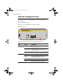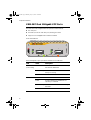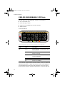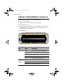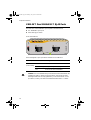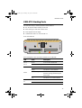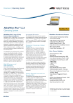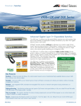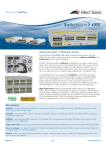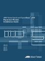
1
x900 Series Switch and SwitchBlade® x908
Expansion Module
Installation Guide
XEM-1XP
XEM-2XP
XEM-12S
XEM-12T
XEM-2XT
XEM-STK
XEM_IG.fm Page 1 Monday, July 19, 2010 10:40 AM
x900 Series Switch and SwitchBlade® x908
Expansion Module Installation Guide
XEM-1XP
XEM-2XP
XEM-12S
XEM-12T
XEM-2XT
XEM-STK
Download the complete document set from
www.alliedtelesis.com/support/software
XEM_IG.fm Page 2 Monday, July 19, 2010 10:40 AM
Expansion Modules
x900 Series Switch and SwitchBlade® x908 Expansion Module Installation Guide
Document Number 613-000032 REV J
© 2005-2010 Allied Telesis, Inc. All rights reserved. No part of this publication
may be reproduced without prior written permission from Allied Telesis, Inc.
Allied Telesis, Inc. reserves the right to change specifications and other
information in this document without prior written notice. The information
provided herein is subject to change without notice. In no event shall Allied
Telesis, Inc. be liable for any incidental, special, indirect, or consequential
damages whatsoever, including but not limited to lost profits, arising out of or
related to this manual or the information contained herein, even if Allied Telesis,
Inc. has been advised of, known, or should have known, the possibility of such
damages.
Allied Telesis, AlliedWare, AlliedWare Plus, and SwitchBlade are trademarks or
registered trademarks in the United States and elsewhere of Allied Telesis, Inc.
Adobe, Acrobat, and Reader are either registered trademarks or trademarks of
Adobe Systems Incorporated in the United States and/or other countries.
Microsoft and Visio are either registered trademarks or trademarks of Microsoft
Corporation in the United States and/or other countries. Additional brands,
names and products mentioned herein may be trademarks of their respective
companies.
2
XEM_IG.fm Page 3 Monday, July 19, 2010 10:40 AM
Installation Guide
Contents
About this Guide .............................................................................................................. 4
Compatible Switches and Operating Systems ........................................................... 4
Compatible Pluggable Optical Modules ....................................................................... 5
Package Contents ............................................................................................................. 5
XEM-1XP 10 Gigabit XFP Port ...................................................................................... 6
XEM-2XP Dual 10 Gigabit XFP Ports .......................................................................... 8
XEM-12S 100/1000BASE-X SFP Ports ...................................................................... 10
XEM-12T 10/100/1000 BASE-T RJ-45 Ports ............................................................. 12
XEM-2XT Dual 10G BASE-T RJ-45 Ports ................................................................. 14
XEM-STK Stacking Ports .............................................................................................. 15
Installation Procedure .................................................................................................... 17
Obtaining Documentation and Resources ............................................................... 21
3
XEM_IG.fm Page 4 Monday, July 19, 2010 10:40 AM
Expansion Modules
About this Guide
Optional expansion modules (XEMs) enable economical combinations of port
type, speed and density in a single switch. Front bays in the switch allow quick
and easy installation.
This Installation Guide describes how to install the following XEMs:
■
XEM-1XP, a single XFP port for high-speed fibre connections
■
XEM-2XP, a dual 10 GbE XFP port expansion module for high-speed fibre
connections
■
XEM-12S, 12 SFP ports for copper and fibre links
■
XEM-12T, 12 x 10/100/1000 Mbps RJ-45 ports for maximum port density
■
XEM-2XT, a dual 10 GbE RJ-45 port expansion module for high-speed
copper connections
■
XEM-STK, dual stacking ports for scalability and high availability
You can download the complete document set for x900 Series switches and
SwitchBlade® x908 from www.alliedtelesis.com/support/software. For more
information about the document set and other resources, see “Obtaining
Documentation and Resources” on page 21.
Compatible Switches and Operating Systems
XEMs can be installed in the following switches:
■
x900-12XT/S
■
x900-24XT
■
x900-24XT-N
■
x900-24XS
■
SwitchBlade x908
The AlliedWare Plus™ Operating System supports all XEMs. The AlliedWare®
Operating System supports all XEMs except the XEM-STK, the XEM-2XP and
the XEM-2XT.
4
XEM_IG.fm Page 5 Monday, July 19, 2010 10:40 AM
Installation Guide
Compatible Pluggable Optical Modules
For the latest list of approved SFP and XFP transceiver modules, contact your
authorised Allied Telesis distributor or reseller. See the most current revision
available of the XEM datasheet (document number 617-000034) for further
information about which SFP or XFP transceiver modules are approved for use.
Package Contents
The following items are included with each XEM:
■
this Installation Guide
■
one warranty card
Contact your authorised Allied Telesis distributor or reseller if any items are
damaged or missing.
5
XEM_IG.fm Page 6 Monday, July 19, 2010 10:40 AM
Expansion Modules
XEM-1XP 10 Gigabit XFP Port
The XEM-1 XP single-port 10 Gigabit Ethernet expansion module features:
■
one XFP port
■
LEDs showing port status
■
support for hot-swappable XFP transceiver modules
XEM-1XP
Front view XEM-1 XP
L/A
XFP
L/A
LINK
ACT
XFP
ENABLED
DISABLED
FAULT
The following LEDs report operations and faults on the XEM-1 XP.
LED
State
Description
L/A
(Link Activity)
Green
An XFP transceiver is installed and a 10 Gb
link has been established.
Green flashing
An XFP transceiver is installed and link
activity is occurring.
Off
A link has not been established.
Green
An XFP transceiver is installed and enabled.
Amber
An XFP transceiver is installed but not
operating or is disabled.
XFP
Amber flashing The installed XFP transceiver has a fault.
Off
6
An XFP transceiver is not installed.
XEM_IG.fm Page 7 Monday, July 19, 2010 10:40 AM
Installation Guide
For the latest list of approved XFP transceiver modules, contact your authorised
Allied Telesis distributor or reseller. See the most current revision available of
the XEM datasheet (document number 617-000034) for further information
about which XFP transceiver modules are approved for use with the XEM-1XP.
Caution It is recommended that you should wait 30 seconds between hot
swapping any XEM to resume normal operations. Also ensure the XEM
fastening thumbscrews are fully tightened. If you are unsure about correct
procedures, contact your authorised Allied Telesis distributor or reseller.
7
XEM_IG.fm Page 8 Monday, July 19, 2010 10:40 AM
Expansion Modules
XEM-2XP Dual 10 Gigabit XFP Ports
The XEM-2 XP Dual 10 Gigabit Ethernet expansion module features:
■
two XFP ports
■
four LEDs (one set for each XFP port) showing port status
■
support for hot-swappable XFP transceiver modules
Front view XEM-2 XP
L/A
XFP
XFP
L/A
LINK
ACT
XFP
ENABLED
DISABLED
XEM-2XP
2
1
L/A
FAULT
The following LEDs report operations and faults on the XEM-2XP.
LED
State
Description
L/A
(Link Activity)
Green
An XFP transceiver is installed and a 10 Gbps
link has been established.
Green flashing
An XFP transceiver is installed and link
activity is occurring.
Off
A link has not been established.
Green
An XFP transceiver is installed and enabled.
Amber
An XFP transceiver is installed but not
operating or is disabled.
XFP
Amber flashing The installed XFP transceiver is not ready or
has a fault.
Off
8
An XFP transceiver is not installed.
XEM_IG.fm Page 9 Monday, July 19, 2010 10:40 AM
Installation Guide
For the latest list of approved XFP transceiver modules, contact your authorised
Allied Telesis distributor or reseller. See the most current revision available of
the XEM datasheet (document number 617-000034) for further information
about which XFP transceiver modules are approved for use with the XEM-2XP.
Caution It is recommended that you should wait 30 seconds between hot
swapping any XEM to resume normal operations. Also ensure the XEM
fastening thumbscrews are fully tightened. If you are unsure about correct
procedures, contact your authorised Allied Telesis distributor or reseller.
9
XEM_IG.fm Page 10 Monday, July 19, 2010 10:40 AM
Expansion Modules
XEM-12S 100/1000BASE-X SFP Ports
The XEM-12 S 12-port 100/1000BASE-X expansion module features:
■
two rows of 6 SFP ports
■
LEDs showing port status
■
support for hot-swappable SFP transceiver modules
■
NEBS compliant
XEM-12S
Front view XEM-12 S
The following LEDs report operations and faults on the XEM-12 S.
LED
State
Description
SFP
Green
An SFP transceiver is installed and a link has
been established.
Green flashing
An SFP transceiver is installed and link
activity is occurring.
Amber
An SFP transceiver is installed but a link has
not been established.
Amber flashing
An SFP is installed but there is a fault.
Off
An SFP is not installed.
For the latest list of approved SFP transceiver modules, contact your authorised
Allied Telesis distributor or reseller. See the most current revision available of
the XEM datasheet (document number 617-000034) for further information
about which SFP transceiver modules are approved for use with the XEM-12S.
10
XEM_IG.fm Page 11 Monday, July 19, 2010 10:40 AM
Installation Guide
Caution It is recommended that you should wait 30 seconds between hot
swapping any XEM to resume normal operations. Also ensure the XEM
fastening thumbscrews are fully tightened. If you are unsure about correct
procedures, contact your authorised Allied Telesis distributor or reseller.
11
XEM_IG.fm Page 12 Monday, July 19, 2010 10:40 AM
Expansion Modules
XEM-12T 10/100/1000 BASE-T RJ-45 Ports
The XEM-12 T 12-port RJ-45 expansion module features:
■
two rows of 6 RJ-45 ports
■
gigabit ports that support speeds of 10/100/1000 Mbps
■
LEDs showing port status
■
cable fault detection and distance-to-fault diagnostics on switches running
the AlliedWare® operating system (see the Test Facility chapter in the
Software Reference for the switch)
XEM-12T
Front view XEM-12 T
The following LEDs report operations and faults on the XEM-12 T.
LED
State
Description
L/A
(Link Activity)
Green
A 1000 Mbps link has been established.
Green flashing
1000 Mbps activity is occurring.
Amber
A 10/100 Mbps link has been established.
Amber flashing 10/100 Mbps activity is occurring.
D/C
(Duplex/
Collision)
Off
A link has not been established.
Green
The port is operating in full duplex mode.
Amber
The port is operating in half duplex mode.
Amber flashing Collisions are occurring.
12
XEM_IG.fm Page 13 Monday, July 19, 2010 10:40 AM
Installation Guide
Caution It is recommended that you should wait 30 seconds between hot
swapping any XEM to resume normal operations. Also ensure the XEM
fastening thumbscrews are fully tightened. If you are unsure about correct
procedures, contact your authorised Allied Telesis distributor or reseller.
13
XEM_IG.fm Page 14 Monday, July 19, 2010 10:40 AM
Expansion Modules
XEM-2XT Dual 10G BASE-T RJ-45 Ports
The XEM-2 XT Dual 10 GBASE-T RJ-45 expansion module features:
■
two 10GBASE-T RJ-45 ports
■
LEDs showing port status
Front view XEM-2 XT
1
L/A
2
XEM-2XT
L/A
L/A
10G LINK
ACT
The following LEDs report operations and faults on the XEM-2XT.
LED
State
Description
L/A
(Link Activity)
Green
A 10 Gbps link has been established.
Green flashing
10 Gbps activity is occurring.
Off
A link has not been established.
Caution It is recommended that you should wait 30 seconds between hot
swapping any XEM to resume normal operations. Also ensure the XEM
fastening thumbscrews are fully tightened. If you are unsure about correct
procedures, contact your authorised Allied Telesis distributor or reseller.
14
XEM_IG.fm Page 15 Monday, July 19, 2010 10:40 AM
Installation Guide
XEM-STK Stacking Ports
The XEM-STK dual-port stacking expansion module features:
■
two 15 Gbps full duplex stacking connections
■
LEDs showing port and stack member status
■
seven-segment stack ID display
■
recessed Select button to reset stack ID to 1
Front view XEM-STK
STATUS
ID
PORT 1
STAT
MASTER
MEMBER
STACK
NEGOTIATING
PORT 2
PORT
LINK
XEM-STK
SELECT
FAULT
The following LEDs report operations and faults on the XEM-STK.
LED
State
Description
Port 1
Port 2
Green
A link has been established.
Amber slow flashing
The link has a transmission fault.
Green
The switch is the stack master.
Amber
The switch is a stack member.
Green flashing
The switch is in the process of learning
the stack topology and selecting the
stack master.
Off
The switch is not a stack member.
1 to 8
Numeric ID of the stack member.
Off
The switch is not a stack member.
Status
ID
15
XEM_IG.fm Page 16 Monday, July 19, 2010 10:40 AM
Expansion Modules
A choice of 0.5 m or 2.0 m stacking cables can be ordered separately. For the
latest list of approved cables, contact your authorised Allied Telesis distributor
or reseller.
The Select button resets the stack ID of this switch to 1, and causes the other
members of the stack to be renumbered. Use this to put the stack into a predefined configuration for ease of installation.
Note You should install only one XEM-STK expansion module in a switch. If
you install more than one, only the first expansion module is enabled.
Caution It is recommended that you should wait 30 seconds between hot
swapping any XEM to resume normal operations. Also ensure the XEM
fastening thumbscrews are fully tightened. If you are unsure about correct
procedures, contact your authorised Allied Telesis distributor or reseller.
16
XEM_IG.fm Page 17 Monday, July 19, 2010 10:40 AM
Installation Guide
Installation Procedure
The installation procedure and XEMs supported by each switch depend on the
operating system running on the switch.
AlliedWare Plus™ Operating System
Switches running the AlliedWare Plus™ operating system support all XEMs. All
XEMs except the XEM-STK are hot-swappable and can be installed following
either of these procedures:
■
“Installing or replacing XEMs without hot swap support” on page 18
■
“Installing or replacing XEMs with hot swap support” on page 19
The XEM-STK is hot-removable only. To remove the XEM-STK, disconnect the
stacking cables, loosen the thumbscrews on the faceplate and remove the XEM.
To install or replace the XEM-STK, follow the procedure “Installing or replacing
XEMs without hot swap support” on page 18.
AlliedWare® Operating System
Switches running the AlliedWare® operating system support all XEMs except
the XEM-STK and the XEM-2XP. XEMs are not hot-swappable under the
AlliedWare® operating system and must be installed following the procedure
“Installing or replacing XEMs without hot swap support” on page 18.
Before you begin
■
Unpack the XEM.
In an anti-static environment, remove the XEM from its packing material. Be
sure to observe ESD precautions.
Caution Failure to observe proper anti-static procedures may damage the
unit. If you are unsure about correct procedures, contact your authorised
Allied Telesis distributor or reseller.
■
Verify the package contents if you have not already done so.
See “Package Contents” on page 5. If any items are damaged or missing,
contact your authorised Allied Telesis distributor or reseller.
■
Read the safety information for the switch.
Safety information is available in the Installation and Safety Guide that is
shipped with each switch. You can also download this document from
www.alliedtelesis.com/support/software.
17
XEM_IG.fm Page 18 Monday, July 19, 2010 10:40 AM
Expansion Modules
■
Gather necessary tools.
You may need a Phillips #2 screwdriver to adjust the thumbscrews on the XEM.
Installing or replacing XEMs without hot swap support
Follow this procedure to:
■
install a XEM, except the XEM-STK, in a switch running the AlliedWare®
operating system
■
install a XEM-STK in a switch running the AlliedWare Plus™ operating
system
■
install a XEM without hot swapping in a switch running the
AlliedWare Plus™ operating system
To install or replace a XEM:
1.
If you are replacing a XEM, first save the switch configuration.
On switches running the AlliedWare® operating system, use the
commands:
create config=<filename>.cfg
set config=<filename>.cfg
On switches running the AlliedWare Plus™ operating system, use the
commands:
awplus>enable
awplus#copy running-config startup-config
2.
If connected, disconnect the switch from its redundant power supply.
3.
Disconnect the switch from its AC or DC power supply.
4.
If you are replacing an existing XEM, disconnect any data cables.
5.
Loosen the thumbscrews on the faceplate or existing XEM, and remove it.
Keep the faceplate for future use. If you remove a XEM, cover the bay with
the faceplate to prevent dust and debris from entering it and to maintain
proper airflow.
18
6.
Carefully slide the new XEM into the empty bay until you feel it engage the
rear plug.
7.
Secure the XEM by tightening the thumbscrews.
8.
Apply power to the switch by re-attaching the power cord.
9.
If you disconnected a redundant power supply, reconnect it.
XEM_IG.fm Page 19 Monday, July 19, 2010 10:40 AM
Installation Guide
10. Restart the switch and verify the installation.
If you have a terminal connected to the asyn0 port, any error message is
displayed during startup self-tests.
Confirm there is no error message about installation in the log file and that
the switch has recognised the XEM.
On switches running the AlliedWare® operating system, use the
commands:
show log
show system
On switches running the AlliedWare Plus™ operating system, use the
commands:
awplus>show system
awplus>enable
awplus#show log
Installing or replacing XEMs with hot swap support
Caution It is recommended that you should wait 30 seconds between hot
swapping any XEM to resume normal operations. Also ensure the XEM
fastening thumbscrews are fully tightened. If you are unsure about correct
procedures, contact your authorised Allied Telesis distributor or reseller.
Follow this procedure to hot swap a XEM in a switch running the
AlliedWare Plus™ operating system. Note that the XEM-STK cannot be hot
swapped.
1.
If you are replacing a XEM, first save the switch configuration, by using the
commands:
awplus>enable
awplus#copy running-config startup-config
2.
If you are replacing an existing XEM, disconnect any data cables.
3.
Loosen the thumbscrews on the faceplate or existing XEM, and remove it.
Keep the faceplate for future use. If you remove a XEM, cover the bay with
the faceplate to prevent dust and debris from entering it and to maintain
proper airflow.
4.
Carefully slide the new XEM into the empty bay until you feel it engage the
rear plug.
5.
Secure the XEM by tightening the thumbscrews.
19
XEM_IG.fm Page 20 Monday, July 19, 2010 10:40 AM
Expansion Modules
6.
Verify the installation.
If you have a terminal connected to the asyn0 port, any error message is
displayed during installation.
Confirm there is no error message about installation in the log file and that
the switch has recognised the XEM, by using the commands:
awplus>show system
awplus>enable
awplus#show log
20
XEM_IG.fm Page 21 Monday, July 19, 2010 10:40 AM
Installation Guide
Obtaining Documentation and Resources
The complete document set for x900 Series switches and SwitchBlade x908
includes:
■
this Installation Guide
■
the x900 Series Switch and SwitchBlade® x908 Installation and Safety Guide,
which describes how to install the switch and includes important safety and
statutory information
■
the x900 Series Switch and SwitchBlade® x908 Hardware Reference, which
contains detailed information on the switch and its hardware features
■
the Removable Power Supply and Fan Installation Guide, which describes how to
install power supply units and fan-only modules in the switch
■
the x900 Series Switch AlliedWare® Operating System Software Reference, which
contains detailed information on configuring switches running the
AlliedWare® operating system
■
the AlliedWare Plus™ Operating System Software Reference, which contains
detailed information on configuring switches running the AlliedWare Plus™
operating system
You can download these documents and updates from
www.alliedtelesis.com/support/software.
You need Adobe® Acrobat® Reader® software to view, search, or print these
documents. You can download it from www.adobe.com.
Other resources
How-To Notes describe a range of standard Allied Telesis solutions, and include
technical tips and guides to configuring specific hardware and software features.
You can download the latest How-To Notes from
www.alliedtelesis.com/resources/literature/howto.aspx.
MIBs supported by Allied Telesis products can be downloaded from
www.alliedtelesis.com/support/software.
Microsoft® Visio® stencils for Allied Telesis products can be downloaded from
www.alliedtelesis.com/resources/images/visio.aspx.
AT-TFTP Server for Windows is a TFTP (Trivial File Transfer Protocol) server for
transferring software versions, configuration scripts and other files between a
PC and the switch. You download AT-TFTP Server from
www.alliedtelesis.com/support/software.
21
XEM_IG.fm Page 22 Monday, July 19, 2010 10:40 AM
Expansion Modules
Contacting us
With locations covering all of the established markets in North America, Latin
America, Europe, Asia, and the Pacific, Allied Telesis provides localized sales and
technical support worldwide. To find the representative nearest you, visit us on
the Web at www.alliedtelesis.com.
22