1
Head Office. Umeda Center Bldg., 4-12, Nakazakinishi 2-chome, Kita-ku, Osaka, 530-8323 Japan.
Tel: 06-6373-4338
Fax: 03-6373-7297
Marine type Container Refrigeration Unit
Tokyo Office. Tokyo Opera City Tower 12F. 3-20-2 Nishi-Shinjuku, Shinjuku-ku, Tokyo 163-1412, Japan.
Tel: 03-5353-7860
Fax: 03-5353-7913
Service Manual
$5,00 (2002.11.00200)NK
LXE10E-A14・LXE10E-A15
TR02-14
Marine type
Container Refrigeration Unit
Service Manual
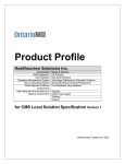
DAIKIN CONTAINER
LXE10E-A14
LXE10E-A15
TR 02-14
Please read the contents of this manual prior to operation of the unit.
This booklet will provide you with the minimum necessary information
required to operate the Daikin refrigerated unit LXE10E-A. It covers all of
the unit's functions from basics such as the names for each mode of
operation, how to turn on the power supply, or change a setting
temperature, to describing functions of product and maintenance service.
In addition, refer to the manuals listed below:
●Parts List
●Operation Manual of Personal Computer Software
1
CONTENTS
Safety Precautions
• Danger .................................................................3
• Warning................................................................4
• Caution.................................................................5
1. Introduction .......................................................1-1
1.1 Operation range ............................................1-1
1.2 Basic Names of components ........................1-1
1.3 Basic operation of refrigeration unit ..............1-2
1.3.1 Starting operation ...................................1-2
1.3.2 Checking during operation .....................1-5
1.3.3 Procedure after operation.......................1-5
2. General description ..........................................2-1
2.1 Main specifications........................................2-1
2.2 Names of components ..................................2-2
2.2.1 Outside ...................................................2-2
2.2.2 Inside......................................................2-3
2.2.3 Control box .............................................2-4
2.3 Set point list of functional parts and protection devices ...2-5
2.4 Operating pressure and running current .......2-6
2.5 Operation modes and control........................2-8
2.5.1 Frozen mode ..........................................2-9
2.5.2 Chilled and partial frozen mode............2-11
2.5.3 Defrosting mode ...................................2-13
2.5.4 Common control ...................................2-16
3. Electronic Controller.........................................3-1
3.1 Function table................................................3-1
3.2 Basic operations of electronic controller .......3-3
3.2.1 Control panel ..........................................3-3
3.2.2 Operation mode and control...................3-5
3.3 Operation procedure .....................................3-6
3.3.1 Operation procedure flow chart ..............3-6
3.3.2 Mode operation procedure .....................3-9
1. Current indication mode .........................3-9
2. Operation setting mode ........................3-10
3. Battery mode ........................................3-11
4. Mode operation ....................................3-12
5. LED display light OFF mode ................3-17
6. Sensor indication mode........................3-18
7. Temperature record scroll mode ..........3-21
8. Alarm record scroll mode .....................3-24
9. PTI record scroll mode .........................3-26
3.3.3 Setting flow chart..................................3-27
10. Optional function mode ......................3-29
11. Basic setting mode .............................3-30
12. Optional condition setting mode .........3-32
13. Input data mode .................................3-34
14. Controller software download mode...3-35
3.4 Alarm display and back-up function ............3-36
3.4.1 Alarm list...............................................3-36
3.4.2 Back-up operation at sensor
malfunction ...........................................3-37
3.5 Battery.........................................................3-39
3.5.1 Specifications .......................................3-39
3.5.2 Function................................................3-39
3.5.3 Battery check........................................3-39
3.5.4 Battery replacement .............................3-40
3.6 Information interchange with personal computer....3-41
3.6.1 Data logging .........................................3-42
3.6.2 Software configuration..........................3-43
3.7 Inspection procedure for electronic controller........3-45
3.8 Controller replacement and initial setting ....3-46
3.8.1 Controller replacement .........................3-46
3.8.2 Initial setting & operation procedure.....3-48
3.9 PTI (Pre Trip Inspection) and periodic inspection...3-49
3.9.1 Inspection item .....................................3-50
3.9.2 Automatic PTI.......................................3-53
3.9.2.1 PTI selection mode........................3-54
3.9.2.2 Short PTI (S.PTI) ...........................3-55
3.9.2.3 Full PTI (F.PTI) ..............................3-56
3.9.2.4 Alarm list during PTI ........................3-58
3.9.2.5 Manual check (M.CHECK) ............3-59
3.10 Chartless function .....................................3-62
3.10.1 Chart indication mode ........................3-62
3.10.2 Chartless code display function..........3-64
3.10.2.1 List of chartless codes .................3-64
3.10.2.2 P code .........................................3-65
3.10.2.3 H code .........................................3-66
3.10.2.4 D code.........................................3-68
3.11 Communication modem (optional) ............3-69
4. Service and Maintenance .................................4-1
4.1 Main components and maintenance .............4-1
4.1.1 Scroll compressor...................................4-1
4.1.2 Air-cooled condenser .............................4-3
4.1.3 Fusible plug ............................................4-3
4.1.4 Drier........................................................4-4
4.1.5 Liquid/moisture indicator ........................4-4
4.1.6 Electronic expansion valve.....................4-5
4.1.7 Suction modulating valve .......................4-6
4.1.8 Solenoid valve ........................................4-7
4.1.9 Discharge pressure regulating valve ......4-8
4.1.10 Check valve..........................................4-9
4.1.11 High pressure switch (HPS) .................4-9
4.1.12 Low pressure switch (LPS).................4-10
4.1.13 High pressure transducer (HPT) ........4-10
4.1.14 Temperature sensors .........................4-11
4.1.15 Humidity sensor..................................4-12
4.2 Fan and fan motor.......................................4-13
4.3 PT and CT board.........................................4-14
4.4 Maintenance service ...................................4-16
4.4.1 Collection of refrigerant ........................4-16
4.4.2 Gauge manifold ....................................4-16
4.4.3 Automatic pump down..........................4-18
4.4.4 Refrigerant recovery and charge..........4-20
4.4.5 Evacuation and dehydrating.................4-24
5. Optional Devices ...............................................5-1
5.1 USDA transportation .....................................5-1
5.1.1 Type of USDA sensor/receptacle ...........5-1
5.1.2 Initial setting ...........................................5-1
5.1.3 USDA sensor calibration ........................5-1
5.1.4 USDA transportation requirement ..........5-1
5.1.5 USDA report ...........................................5-1
6. Troubleshooting................................................6-1
6.1 Refrigeration and electrical system..................6-1
6.2 Alarm codes on electronic controller
(F-code/E-code) ............................................6-4
6.3 Troubleshooting for automatic PTI (J-code) .....6-8
6.4 Diagnosis based on recording chart............6-10
6.5 Emergency operation ..................................6-13
6.5.1 Emergency operation of controller .......6-13
6.5.2 Short circuit operation of controller.......6-14
6.5.3 Emergency operation of electronic
expansion valve....................................6-16
6.5.4 Emergency operation of suction modulating
valve .....................................................6-17
6.5.5 Automatic Back up for supply- and return
air temperature sensors (optional) .......6-18
7. Appendix............................................................7-1
7.1 Standard tightening torques for bolts ............7-1
7.2 Standard tightening torques for flare nuts ........7-1
7.3 Resistance of motor coil and solenoid valve coil ...7-1
7.4 HFC 134a temperature-vapor pressure
characteristics table ......................................7-2
7.5 Temperature sensor characteristics table .....7-3
7.6 Temperature sensor characteristics table DCHS ...7-4
7.7 High pressure transducer characteristics table...7-4
7.8 Low pressure transducer characteristics table...7-4
7.9 Piping diagram ..............................................7-5
7.10 Pilot lamps and monitoring circuit ...............7-6
7.11 Fuse protection table...................................7-7
7.12 Schematic wiring diagram ...........................7-8
7.13 Stereoscopic wiring diagram .......................7-9
INDEX
SAFETY PRECAUTIONS
Always observe the following points before operating or
inspecting a unit.
DANGER
Always turn off the main power supply to the facility
before disconnecting the power plug.
Always turn off the main power supply to the facility
before inspecting the interior of the control box.
※This is important because high voltage remains at the
circuit breaker and the optionally provided modem even
though the circuit breaker in the control box is turned off.
Modem (optional)
PAK35J
PAK-61JC
PAK-61JC
PAK-61JC
B4P–VH
B4P–VH
FUSE
B5P-VH
B3PSVH
RAÅ|H341TD
Circuit breaker
High voltage
3
WARNING
Do not touch the condenser fan while power to the
unit is ON.
Before removing the condenser fan cover, turn off the
circuit breaker and disconnect the power plug.
During air-cooled operation : Condenser fan may start
and stop automatically for
the refrigerant high
pressure control.
During water-cooled operation: Condenser fan may start
and stop automatically for
cooling of the control box.
4
CAUTION
Before starting the unit, run the generator.
Securely close the control box cover.
Otherwise, it will allow water entry.
Control box cover
Quick-lock lever
5
CAUTION
Wash the refrigeration unit with fresh water at PTI.
Carefully flush the air-cooled condenser with fresh water to
remove the salt that sticks to it.
6
CAUTION
Refrigerant and refrigerant oil
Be sure to only charge the unit with refrigerant HFC 134a.
Never attempt to use any other refrigerant (CFC12, HCF22, etc) with the
refrigeration unit.
If any other refrigerant not specified is charged, it may cause problems with the unit.
Use only Daikin specified oil (IDEMITSU, Daphne Hermetic Oil FVC46D) when
replacing the refrigerant oil.
If any other refrigerating machine oil not specified is charged, it may cause problems
with the unit.
DA P H N E
S W -4 6
F V C46 D
OIL
HE
R M E TI C O I L
DAPHNE
HERMETIC OIL
FVC46D
SUNISO
3GS-DI
Open the oil can, just before charging the oil, and use all the oil in the can once
opened.
Do not leave the can open for 5 hours or longer to avoid moisture entry.
Using any refrigerant oil which has absorbed moisture may cause problems with the
unit.
Moisture
Moisture
Use only exclusive tools for HFC134a. (gauge manifold, charging cylinder, etc)
Do not use any tools for CFC12 or HCFC22.
Service ports with exclusive quick joints for HFC134a are provided in the refrigeration
unit to avoid improper refrigerant or refrigerant oil from entering into the refrigeration
circuit. (Refer to section 4.4.2)
The charging hose and gauge port are not interchangeable with those of previous
models using other refrigerants.
7
CLASS 1 SPECIFIED PRODUCT BY
THE HYDROFLUORIC REFRIGERANT RECOVERY LAW
HFC IS USED FOR THIS PRODUCT AS A REFRIGERANT.
(1) EMISSION OF HYDROFLUORIC SUBSTANCES INTO THE ATMOSPHERE
WITHOUT PERMISSION IS PROHIBITED.
(2) RECOVERY OF HYDROFLUORIC SUBSTANCES IS MANDATORY WHEN
SCRAPPING THIS PRODUCT.
(3) THE KIND OF HYDROFLUORIC SUBSTANCE AND ITS AMOUNT ARE STATED IN
THE MANUFACTURER'S LABEL OR THE ADDITIONALLY CHARGED AMOUNT
LABEL.
8
1. Introduction
1.1 OPERATION RANGE
Use the units within the following range.
Item
Operation range
Ambient temperature range
-30˚C to +50˚C (-22˚F to + 122˚F)
Inside temperature range
-30˚C to +30˚C (-22˚F to + 86˚F)
Voltage
50Hz: 380V/400V/415V, 60Hz: 440V/460V
Voltage fluctuation rate should be within ±10%
Vibration and shock
2G
1.2 BASIC NAMES OF COMPONENTS
8
11
6
10
4
5
2
13
3
9
7
1
12
q
Compressor
i
Access panel
w
e
Air-cooled condenser
Receiver
o
!0
Storage space for power cable
Ventilator
r
t
Evaporator
Control box
!1
Sampling port (Return) Use this port to measure the
inside return air temperature.
!2
This is used to measure the
Gas sampling port
Sampling port (Supply) inside supply air temperature
Outside: switch, manual defrost switch, monitoring
receptacle
Inside: circuit breaker
y
u
Condenser fan
Drier
and inside CO2 concentration.
!3
1-1
Liquid moisture indicator
1.3 BASIC OPERATION OF
REFRIGERATION UNIT
w
Operate the unit by the following
procedure.
1.3.1 Starting operation
(1) Make sure that power to the unit is on.
CAUTION
Make sure that the power plug q, the circuit
breaker w, and the UNIT ON/OFF key e are
OFF. Otherwise, it will be dangerous while
checking.
1
e
1-2
(2) Adjust the ventilation.
Adjust the opening of the ventilation !0
according to the cargo.
CAUTION
Keep the ventilation closed during
transportation of the frozen cargo.
When ventilation is not required (frozen mode),
set the handle to "CLOSE".
When ventilation is required (chilled mode),
slide the handle upward.
※Set the arrow mark of the ventilation at the
graduation on the scale to adjust the
ventilation as desired according to the cargo.
!4
!1
!3
!2
!1
!2
!3
!4
!5
Ventilation cover
Handle
Nameplate
Air inlet
Air outlet
!5
!0
1-3
!4
!5
(3) Connect the power plug to the power supply.
Insert the plug !6 suited to the power source
voltage, and fasten the plug firmly.
(4) Turn on the main power switch of the power
source facility (outside the unit)
!6
(5) Turn on the circuit breaker !7.
Power plug
(6) Close the control box cover fully.
If it is poorly closed, it will allow water entry.
Check the contact around the packing, and
firmly close the cover. (Refer to the
"
CAUTION " on page 5.)
!7
(7) Press the UNIT ON/OFF key !8.
!8
1-4
1.3.2 Checking during operation
Checking items(precautions)
Method of check
1. Check the compressor, fan, pipes, etc. for abnormal noise and vibration. Visual and auditory
Visual
2. Check the refrigerant for shortage.
Bubbles in moisture indicator on PULLDOWN or
FROZEN operation may mean shortage of refrigerant in the
system.
Charge specified amount of refrigerant to the system, if inside
temperature cannot maintain the setting temperature due to
shortage of refrigerant.
Please note, there will be bubbles in the moisture indicator
after the unit starts and in chilled operation. This is normal.
3. Check the refrigerant for moisture inclusion.
Visual
The moisture indicator colour;
Green: normal
Yellow: abnormal.
Visual
4. Check operating conditions with the pilot lamps.
Liquid moisture indicator
qPower plug
w
1.3.3 Procedure after operation
(1) Turn off the UNIT ON/OFF key e, and turn off
the circuit breaker w.
(2) Close the control box cover tightly.
(3) Stow the power cable.
Disconnect the power plug q, and stow the
power cable directing the plug opening
downward to prevent sea water or rain water
from collecting in the power plug.
q
e
1-5
2. General description
2.1 Main specifications
Model
LXE10E
Item
Condenser cooling system
Controller
DECOS3C
Power supply
AC 3-phase 380V/400V/415V 50Hz, 440V/460V 60Hz
Compressor
Hermetic scroll type (Motor output: 5.5kW)
Evaporator
Cross fin coil type
Air-cooled condenser
Cross fin coil type
Evaporator fan
Evaporator fan motor
Condenser fan
Condenser fan motor
Defrosting
Air cooled type
Propeller fan
Three-phase squirrel-cage induction motor
Propeller fan
Three-phase squirrel-cage induction motor
System
Hot-gas defrosting system
Initiation
Dual timer, on-demand defrost and manual switch
Termination
Refrigerant flow control
Capacity control
Detecting the temperature of evaporator outlet pipe and return air
Electronic expansion valve
Capacity control with hot gas bypass and suction modulating valve
Circuit breaker, PT/CT board (for over current protection).
Protective devices
/Safety devices
Compressor thermal protector
Condenser fan-motor thermal protector
Evaporator fan-motor thermal protector
High-pressure switch, Fusible plug, Fuse (10A, 5A)
Refrigerant (charged amount)
Refrigerant oil (charged amount)
Weight
R134a : 4.6 (kgf)
IDEMITSU, Daphne hermetic oil FVC 46D : 2.2(R)
LXE10E-A14 : 465(kgf)
LXE10E-A15 : 495(kgf)
2-1
2.2 Names of components
2.2.1 Outside
●LXE10E
1
2
3
27
28
4
5
6
7
8
9
26
25
24
23
22
10
11
12
13
21 20 19 18 17 16 15 14
q
w
e
r
t
y
u
i
o
!0
!1
!2
!3
!4
!5
!6 Discharge pressure regulating valve (DPR)
!7 Compressor suction pipe temperature
sensor (SGS)
!8 Ambient temperature sensor (AMBS)
!9 Thermometer check port (Supply air)
@0 Compressor (MC)
@1 Discharge pipe temperature sensor
(DCHS)
@2 Storage space for power cable
@3 Low pressure transducer (LPT)
@4 High pressure transducer (HPT)
@5 High pressure switch (HPS)
@6 Control box
@7 Ventilation
@8 Reheat coil solenoid valve (RSV)
Access panel
Thermometer check port (Return air)
Condenser fan motor (CFM)
Hot-gas solenoid valve (HSV)
Defrost solenoid valve (DSV)
Discharge gas by-pass solenoid valve (BSV)
Electronic expansion valve (EV)
Economizer solenoid valve (ESV)
Injection solenoid valve (ISV)
Air-cooled condenser
Liquid/moisture indicator
Liquid receiver
Drier
Liquid solenoid valve (LSV)
Suction modulating valve (SMV)
2-2
2.2.2 Inside
●LXE10E
10
6
1
7
2
5
8
11
4
3
q Evaporator fan motor (EFM)
w Evaporator
e Supply air temperature sensor (SS)
Data recorder supply air temperature sensor (DSS)
Recorder supply air temperature sensor (RSS, optional)
r Evaporator outlet pipe temperature sensor (EOS)
t Evaporator inlet pipe temperature sensor (EIS)
y Return air temperature sensor (RS)
Data recorder return air temperature sensor (DRS, optional)
Recorder return air temperature sensor (DRS, optional)
u USDA receptacle (optional)
i Cargo temp. receptacles
o P.C. Port receptacles
!0 Humidity sensor
!1 Reheat coil
2-3
9
2.2.3 Control box
●Inside of the control box
4
5
6
8 20 9 10
7
19
22
PAK35J
PAK-61JC
PAK-61JC
PAK-61JC
18
B4P–VH
B4P–VH
17
16
FUSE
B5P-VH
B3PSVH
RA–H341TD
15
21
12 11
●Operation panel
(Outside of the control box)
COMP.
●Controller
OVER
SP+ ˚C
5
INRANGE
UNDER
S P – 5 ˚C
1
DEFROST INRANGED–HUMID
SUPPLY
RETURN
ALARM
R.H.
˚C / ˚F
%R H
1
2
3
1 HOURS
2 DAYS
–12
–6
–10
–5
–8
–4
–6
–3
–4
–2
DAIKIN ELECTRONICCONTAINER OPERATION SYSTEM
–2
–1
DECOS
b
14
13
11
q
w
e
r
t
y
u
i
o
!0
!1
Controller operation panel (EC3, 4)
MANUAL DEFROST key
UNIT ON/OFF key
Phase correction contactor (PCC1,2)
Magnetic contactor for high speed evaporator fan (EFH)
Magnetic contactor for low speed evaporator fan (EFL)
Magnetic contactor condenser fan (CFC)
Reverse phase protection device (RPP)
Adopter PCB (EC6)
Terminal block board (TB1)
Controller CPU / IO board (EC1, 2)
2-4
!2
!3
!4
!5
!6
!7
!8
!9
@0
@1
@2
Fuse (Fu1-6)
Rechargeable battery (BAT)
Voltage indicator
Personal computer receptacle
Circuit breaker (CB)
PT/CT board
Transformer (TrC), control circuit
Magnetic contactor for compressor (CC)
P.C.B for humidity sensor (HUS, optional)
Modem (RCD, optional)
Noise filter (NF, optional)
2
3
2.3 Set point of functional parts and protection devices
Pressure switch
Device name
Actuation
High-pressure switch
HPS
Water pressure switch
OFF
98kPa (1.0kg/cm2)
Water pressure switch
WPS
(optional)
ON
ON
39kPa (0.4kg/cm )
+30.0°C to –2.9°C
Set point temperature
EC
2
(+86.0°F to +26.8°F)
–3.0°C to –10.0°C
Partial frozen mode
(+26.6°F to +14.0°F)
Frozen mode
–10.1°C to –30.0°C
(+13.8°F to –22.0°F)
ON
10 seconds
60 seconds
ON
4 hours ※1
3, 6, 9, 12, 24 and 99 hours(※2)
Back-up
In-range masking
OFF
90 minutes
90 minutes
Out-range guard
Defrosting termination set point
ON
OFF
30 minutes
30˚C (86°F)
Delay
timer
Fan
Change-over for Hi/Lo
After defrosting
Initiation
Compressor At starting
Defrosting
timer
Electronic controller
Symbol
2400kPa (24.47kg/cm2)
1900kPa (19.37kg/cm2)
Mode selection
3 seconds
Short
Long
※6
※3
Evaporator outlet
Reset
High-pressure control for Condenser fan
(※Frozen only)
OFF
ON
※4
800kPa (8.2kg/cm2) ※7
1000kPa (10.2kg/cm2)
Return air temperature
sensor
High-pressure transducer
Discharge gas
Pull down
OFF
135˚C (275°F)
Discharge gas
temperature
protection
LPT>50kpa
LPT≦50kpa
Reset
OFF
After 3 minutes elapsed
128˚C (262°F)
temperature sensor
Reset
OFF
After 3 minutes elapsed
26.0A
Reset
After 3 minutes elapsed
Current control
Control
High pressure control
Control
EOS
tempertature sensor
15˚C (59°F)
set point
Overcurrent protection set point (Cutout)
Current
Detection method
OFF
ON
Chilled mode
Motor
Set point
High-pressure switch
50Hz : 16.1A
60Hz : 17.4A
2300 to 2350 kPa
(23.5 to 24.0 kg/cm2)
Circuit breaker
OFF
30A
Fuse
OFF
5A, 10A
Evaporator fan motor thermal protector
OFF
132˚C (270°F)
Condenser fan motor thermal protector
Compressor motor thermal protector
OFF
OFF
135˚C (275°F)
140˚C (284°F)
RS, DRS
HPT
DCHS
PT/CT board
CT2
PT/CT board
CT1
High pressure sensor
HPT
CB
※5
Fu
MTP
CTP
(※1) When Return air (RS) is lower than –20˚C, defrost starts every 6 hours.
(※2) When "99" hours is selected, refer to on demand defrost in 2.5.3.
(※3) When Inside set point is –20.0˚C or Lower, In-range masking is 120min.
(※4) If defrost is initiated when inside temperature is out rangle area. (= In-range LED is not light), this condition is added to
finish defrost. Refer to "Defrosting termination" in 2.5.3.
(※5) Refer to "Fuse Protection table" in 7.11.
(※6) In Bulb mode, this setting can be adjusted. (Refer to "Bulb mode" Page 2-20)
(※7) When dehumidification is ON in Bulb and dehumidification mode, the setting figure may change between 900~2100kPa
automatically (Refer to "High Pressure Control" Page 2-17)
2-5
2.4 Operating pressure and running current
●Chilled mode
Inside : 0°C (32°F)
Power supply :
400V / 60Hz
16
15
14
13
12
Total current
11
10
9
8
7
2
(kPa)
(kg/cm)
2000
20
High pressure
1500
15
1000
10
500
5
0
0
(kg/cm2)
(kPa)
200
2.0
Low pressure 100
1.0
0
0
–100
5
(41
10
50
15
59
–76B Hg
20 25 30 35 40 45 50 (˚C)
68 77 86 95 104 113 122) ( F )
Ambient temperature
●Fan motor current
Item
Condenser fan motor
running current
Evaporator fan motor
running current (2 motors)
2-6
Amperage
1.4 (400VAC)
3.2 (400VAC)
Hi speed
●Frozen mode
Inside: –18˚C (–0.4˚F)
16
Power supply: 400V, 60Hz
15
14
13
12
Total current
11
10
9
8
7
(kPa)
(kg/cm2)
2000
20
High pressure
1500
15
1000
10
500
5
0
0
(kg/cm2)
(kPa)
200
2.0
Low pressure 100
1.0
0
0
–100
5
(41
10
50
–76B Hg
15 20 25 30 35 40 45 50 (˚C)
59 68 77 86 95 104 113 122) ( F )
Ambient temperature ˚C (˚F)
●Fan motor current
Item
Condenser fan motor
running current
Evaporator fan motor
running current (2 motors)
2-7
Amperage
1.4 (400VAC)
0.9 (400VAC)
Low speed
2.5 OPERATION MODES AND CONTROL
There are two main types of operation modes: the cargo cooling control mode and the unit
inspection mode.
The cargo cooling control mode is explained in this section.
※For the unit inspection mode, refer to section 3.9.
The relationship between the operation mode and setting temperature is as follows.
Operation mode
Setting temperature
–10.1˚C to –30.0˚C
(+13.8˚F to –22.0˚F)
Control sensor
Return air
temperature sensor
Partial frozen
mode
–3.0˚C to –10.0˚C
(+26.6˚F to +14˚F)
Return air
temperature sensor
Chilled mode
+30.0˚C to –2.9˚C
(+86˚F to +26.8˚F)
Supply air
temperature sensor
–
–
Frozen mode
Defrosting mode
※For details, refer to section 3.1 to 3.4.
2-8
Operation description
Compressor ON/OFF control
Capacity control operation
with suction modulating valve
and hot-gas bypass control
Capacity control operation
with suction modulating valve
and hot-gas bypass control
Hot-gas defrosting with
refrigerant metering control
2.5.1 Frozen mode
Control state transition and common control
Thermostat ON (Pull-down range)
●Compressor
Running
●Evaporator fan
Low speed (L)
Continuous compressor running for
2 minutes or more and RS ≤ SP
RS > SP + 1.0˚C
Pump down
●Compressor
●Evaporator fan
Running
Low speed
LPT<–50kPa
Thermostat OFF
●Compressor
●Evaporator fan
RS : Return air temperature
SP : Setting point temperature
Stop
Low speed
LPT : Low pressure transducer
Solenoid valve
Magnetic
contactor
Operation of magnetic contactor and solenoid valve
Component name
Compressor
Evaporator fan. High speed
Evaporator fan. Low speed
Condenser fan
Liquid solenoid valve
Economizer solenoid valve
Injection solenoid valve
Hot-gas solenoid valve
Defrost solenoid valve
Discharge gas by-pass solenoid valve
Suction modulating valve
Electronic expansion valve
CC
EFH
EFL
CF
LSV
ESV
ISV
HSV
DSV
BSV
SMV
EV
Thermostat ON
ON
OFF
ON
ON / OFF※1
ON
ON(OFF※3)
OFF(ON※2)
OFF
OFF
OFF
Note) ※1: High pressure control
※2: Injection control (Refer to Page 2-18)
※3: Economizer control (Refer to Page 2-19)
2-9
Pump down
ON
OFF
ON
ON / OFF※1
OFF
ON(OFF※3)
OFF(ON※2)
OFF
OFF
OFF
100%
10 to 100%
Thermostat OFF
OFF
OFF
ON
OFF
OFF
OFF
OFF
OFF
OFF
OFF
(1) Set point temperature and control sensor
When the set point temperature (referred to as SP hereafter) is –10.1˚C(+13.8˚F) or lower, the
compressor is operated ON and OFF, in response to return air temperature.
(2) Control
qWhen the control temperature reaches SP (point A), the
compressor and condenser fan are turned off after the liquid
solenoid valve has been de-energized and the pump down
operation has been completed.
wWhen the control temperature exceeds SP+1.0˚C, the compressor,
liquid solenoid valve and condenser fan are turned on.
However, the compressor runs for at least 2 minutes every
time once it is turned on. Even if the control temperature
becomes SP or lower (point C) within 2 minutes after the
compressor is turned on, the compressor, condenser fan
and liquid solenoid valve are not turned off. (2 minutes
compressor forced operation)
–10˚C
SP+2˚C
SP+1˚C
SP
SP–1˚C
SP–2˚C
A
EV
Receiver
FROZEN (Return air < 5˚C)
EV:Elec.Exp.Valve
LSV:Liquid Solenoid Valve
DSV:Defrost Solenoid Valve
ESV:Economizer Solenoid Valve
DPR:Discharge pressure regulator
SMV:Suction Modulation Valve
HSV:Hot Gas Solenoid Valve
ISV:Injection Solenoid Valve
BSV:Discharge gas Bypass Solenoid Valve
LPT:Low Pressure Transducer
HPT:High Pressure Transducer
HPS:High Pressure Switch.
2-10
C
2.5.2 Chilled and partial frozen mode
Control state transition and common control
START
TS≧SP+1.5˚C
TS<SP+1.5˚C
Heat-up
Pull-down
TS≦SP+1.5˚C RS≧SP+1.0˚C
TS≧SP+5.0˚C
Capacity control
TS≧SP+1.0˚C
and 3-minutes
elapse
(TS≦SP–3.0˚C
and 3-minutes elapse)
or (TS≦SP–0.5˚C
and 30-minutes elapse)
Overcool protection
TS≦SP–0.5˚C and 3-minutes elapse
TS : Control temperature (supply air sensor or return air sensor)
SP: Set point temperature
Operation of magnetic conductor and solenoid valve
Component name
Solenoid valve
Magnetic
contactor
Compressor
Evaporator fan. High speed
Evaporator fan. Low speed
Condenser fan
Liquid solenoid valve
Economizer solenoid valve
Injection solenoid valve
Hot-gas solenoid valve
Defrost solenoid valve
Discharge gas by-pass solenoid valve
Suction, modulating valve
Electronic expansion valve
Capacity
Heat-up
control
ON
ON
ON
ON
ON
ON
OFF
OFF
OFF
ON / OFF※1 ON / OFF※4 ON / OFF※1
ON
ON
OFF
OFF
OFF
OFF
ON / OFF※2 ON / OFF※4 ON / OFF※3
OFF
ON / OFF※4
ON
OFF
ON / OFF※4
ON
OFF
ON / OFF※4
OFF
100%
3 to 100%
100%
10 to 100%
10 to 100%
0%
Pull-down
CC
EFH
EFL
CF
LSV
ESV
ISV
HSV
DSV
BSV
SMV
EV
Note) ※1: High pressure control ※2: Discharge gas temperature control
※3: Charge control
※4: Capacity control and hot gas by-pass
2-11
Overcool
protection
OFF
ON
OFF
OFF
OFF
OFF
OFF
OFF
OFF
OFF
100%
50%
(1) Set point temperature and control sensor
™Chilled operation
When the set point temperature is –2.9˚C (+26.8˚F) or higher, the suction modulating valve (SMV) is
controlled sensing the supply air temperature in order to adjust the cooling capacity.
™Partial frozen operation
When the set point temperature is –3.0 to –10.0˚C (+26.6 to +14.0˚F), the suction modulating valve is
controlled sensing the return air temperature in order to adjust the refrigerating capacity.
™Operation mode switching
Operation mode is automatically switched according to the set point of the electronic controller. Chilled
and partial frozen operations are controlled in the same manner except the sensor for the temperature
control.
(2) Control
(a) Pull-down operation
Pull-down operation is carried out with fully opened suction modulating valve when the control
temperature is higher than the set point temperature for 1.5˚C or more (point q).
(b) Capacity control operation
When the control temperature reaches the point w, the in-range lamp is turned on. At the same
time, the suction modulating valve is activated to conduct the capacity control operation.
The control temperature converges to the set point
1
temperature (point e) while repeats temperature
+ 2˚C
increasing and decreasing.
5
During capacity control, hot gas by-pass (HSV, DSV, BSV)
2
+ 1˚C
and liquid injection (ISV) are conducted in order to maintain
3
SP
the optimum operation condition of refrigerant system.
(c) Heat-up operation
– 1˚C
When the control temperature is lower than [set point
– 2˚C
temperature +1.5˚C] (point r), the heat-up operation
4
– 3˚C
6
using hot gas is conducted in order to raise the return air
temperature to the [set temperature +1.5˚C] (point t).
(d) Overcool protection operation
Although the unit's operation is in a stable state, if the control temperature lowers below set point
temp –3˚C (point y), the compressor stops and only the evaporator fan continues to operate.
EV
RECEIVER
2-12
2.5.3 Defrosting mode
Start defrosting
Yes
●Defrost lamp (red) ON
●Pump down
Defrosting range
●Compressor
●Evaporator fan
●Condenser fan
●Defrosting solenoid valve
●Hot gas solenoid valve
ON
OFF
ON/OFF
ON
ON
Is terminating
condition OK?
No
Yes
Defrosting lamp (red) OFF
Evaporator fan On after delay of 60 seconds
Return to frozen, chilled or partial
frozen operation
Solenoid valve
Magnetic
contactor
Operation of magnetic contactor and solenoid valve
Component name
Compressor
Evaporator fan. High speed
Evaporator fan. Low speed
Condenser fan
Liquid solenoid valve
Economizer solenoid valve
Injection solenoid valve
Hot-gas solenoid valve
Defrost solenoid valve
Discharge gas by-pass solenoid valve
Reheat solenoid valve
Suction modulating valve
Electronic expansion valve
CC
EFH
EFL
CF
LSV
ESV
ISV
HSV
DSV
BSV
RSV
SMV
EV
Pump down
ON
Defrosting
ON
ON/OFF※3
OFF
ON/OFF※1
OFF
ON/OFF※4
OFF (ON※5)
OFF
OFF
OFF
OFF
100%
10 to 100%
ON/OFF※1
OFF
OFF
ON/OFF※2
ON
ON
OFF
OFF(ON※6)
100%
5%
Note) ※1: Pressure control
※2: Charging control
※3: Frozen mode ... EFL ON, Chilled mode ... EFH ON
※4: Economizer control
※5: Discharge gas temperature control
※6: EOS>15˚C
2-13
Defrosting operation
(1) Defrosting system
A hot-gas defrost system is adopted in the units; i.e. the high temperature and high pressure refrigerant
(hot gas) from the compressor is sent to the evaporator and drain pan for defrosting. Since the evaporator
is heated directly by the hot gas (refrigerant), defrosting can be performed effectively.
(2) Defrosting initiation
Defrosting is initiated by the timer or the manual defrost key.
However, defrosting is not initiated when frosting on the evaporator can not be detected.
¡Evaporator inlet temperature : 5˚C or higher
¡Evaporator outlet temperature : 20˚C or higher
qInitiation by timer (Timer is set at the electronic controller, refer to section 3.3.2 for its operating method.)
Type of timer
Long timer
Defrosting interval set
3, 6, 9, 12, 24 and 99※1 hours are
selectable.
Short timer
4 hours※2
Out-range timer
30 minutes
Function
Regardless of the control temperature, defrosting
is initiated according to the selected interval.
Defrosting is initiated every 4 hours until the control
temperature comes within the in-range after pull-down.
When the temperature is in-range, defrosting timer
will change into the selected long timer.
After the control temperature comes within
in-range once, defrosting will be started 30 minutes later if
the control temperature rises out of the in-range.
※1. Refer to "(3) On-demand defrost"
※2. 6 hours when the control temperature is –20˚C or below.
wStarting by MANUAL DEFROST key (on the operation panel sheet key)
Press the MANUAL DEFROST key, then press the ENTER/ESC key while indicate "ON" on the LED
display. The manual defrosting operation starts.
eInitiation by frost detection
If the suction air temperature does not drop at the speed of 0.2˚C/1hr during frozen pull-down
operation, defrosting will be initiated because it is judged that frost is formed on the evaporator.
However, if the suction temperature is –20˚C or lower, defrosting will not be initiated. (activated)
(3) On demand defrost
When "99" in long timer is selected, defrosting is activated upon the condition of frost on evaporator
coil. This function is only for Frozen setting (SP < –10.1 deg C). and starting with 12 hours.
(If this function is selected for chilled setting, defrost initiates every 6 hours automatically.)
Procedure:
Step 1: After defrost, the controller records compressor running time for 1st 1 hour. (T1)
Step 2: When 12 hours passed after defrost, controller records compressor running time for last 1
hour (T2). And the controller check whether the below condition is satisfied.
T2 > T1×1.15
Step 3: If the above condition is satisfied, defrost is activated.
If above condition is not satisfied, defrost is postponed another one hour.
After counting up 13 hours, then repeat "Step 2".
Defrost will be postponed every one hour until the above condition (Step 2) is satisfied.
(Max. 24 hours)
2-14
(4) Defrosting termination
Defrosting will be terminated when any one of the following three conditions is satisfied.
qThe below figure is satisfied during defrost.
Status before defrost
INRANGE
OUTRANGE
Termination
EOS≧30.0˚C
EOS≧30.0˚C+RS/DRS≧15˚C
w90 minutes have elapsed.
eAny one of protective devices is activated.
Release
Charge
2-15
2.5.4 Common control
The following are controlled in different operation modes. (For the details, refer to the following pages.)
Control name
Control content
The compressor is operated on and off to
adjust the inside temperature.
At the start of the operation with low ambient
Starting control
temperature,an oil temperature raising control is executed.
When a protection device activates at the operation
start, a high pressure/current control is executed.
The evaporator fan is switched to the high or low
Evaporator fan speed control
speed according to the set point temperature.
In order to keep the superheat of the evaporator
Superheat control
optimum,the opening of the electronic expansion
valve is controlled.
In order to keep the high pressure optimum, the
High-pressure control
opening of the electronic expansion valve is controlled.
In order to prevent the refrigerant oil from
Injection
deteriorating, the injection solenoid valve control or
electronic expansion valve control is carried out.
When the control temperature is within SP ±2˚C,
In-range control
the in-range lamp is turned on.
After defrosting initiation, the in-range lamp
In-range masking control
is kept on for 90 minutes.
The circulating flow rate of refrigerant is proportionally
Capacity control
controlled with suction modulating valve to keep the
control temperature variation within ±0.5˚C.
These functions control the heating capacity
Charging and releasing control
for defrosting and heating operation.
The liquid refrigerant is collected into the liquid receiver
Pump down control
(water cooled condenser).
The economizer circuit is controlled to enhance
Economizer control
cooling capacity.
The unit can execute dehumidification by
Dehumidification (optional)
reheat coil and humidity sensor.
For flower bulb transportation, the unit is
Bulb mode (optional)
equipped with bulb mode control.
A Compressor ON/OFF control
B
C
D
E
F
G
H
I
J
K
L
M
N
2-16
Operation mode
Frozen Chilled Partial
frozen Defrost
Common control
A : Compressor ON/OFF control
When the control temperature reaches the set temperature or lower, the compressor is stopped.
When the control temperature rises and becomes higher than the [set point temperature +1.0˚C], the
compressor runs again.
When the compressor starts running it is forcibly run for 2 minutes. (2 minutes compressor forced
operation) in order to prevent the compressor from deterioration due to shortage of lubricant.
+ 2 ˚C
+ 1 ˚C
Set
temperature
– 1 ˚C
Compressor
Return air temperature
Time
1 minutes
2 minutes compressor forced operation
ON
OFF
B : Starting control
™Control when protective device activated
When the high pressure rapidly rises on starting or when the starting current is overcurrent, the
compressor automatically stops and starts to suppress high pressure and starting current.
™Temperature control of refrigerant oil
When ambient temperature is low, the temperature refrigerant oil for compressor is also low and
the viscosity of the oil may be high.
On starting the unit, by-pass discharge gas to suction side of the compressor by opening the
solenoid valve (BSV) to raise the oil temperature rapidly ensuring a stable feed of oil.
The temperature control for refrigerant oil should be executed not with power ON/OFF in normal
operation but with power ON under low ambient temperature.
An oil temperature raising control can be executed when all of the following conditions are met.
• The time turning power supply ON
• Ambient temperature ≦ 10˚C
• (Discharge gas temperature – ambient temperature) ≦ 4˚C
C : Evaporator fan speed control
The speed of the evaporator fan is switched in accordance with operation modes. A delay time of 10
sec. is provided to switch the high speed to low speed and vice versa.
Chilled mode
: High speed
Partial frozen mode : High speed
Frozen mode
: Low speed
D : Superheat control
The evaporator superheat is adjusted to be optimum by controlling the opening of the electronic
expansion valve, based on the evaporator inlet and outlet refrigerant temperature, and the
compressor suction gas temperature.
E : High-pressure control
• By electronic expansion valve
When the ambient temperature is high during the air-cooled operation, the condensing pressure
(high pressure) will increase, and the high pressure switch may be activated.
In order to prevent this situation, the high pressure is controlled to be 2350kPa or lower by
adjusting the opening of the electronic expansion valve.
• By condenser fan
When the ambient temperature is low during the air-cooled operation, the condenser pressure
(high pressure) will decrease. Accordingly, the low pressure will decrease.
In order to prevent this situation, when the high pressure becomes set point or lower, the
condenser fan stops to prevent the high pressure from excess dropping.
When the high pressure becomes set point or higher afterwards the operation will be restarted.
This control varies upon dehumidification setting.
2-17
Dehumidification : OFF
Dehumidification : ON
High pressure ≦ 800kPa
High pressure ≦ 700~1800kPa
ON
ON
OFF
OFF
High pressure > 1000kPa
High pressure > 900~2100kPa
F : Injection control
In order to decrease the discharge gas temperature, inject liquid refrigerant into the suction pipe.
• During normal compressor operation
The injection solenoid valve will be turned on or off to control the discharge gas temperature lower
than set point.
The control is conducted properly by using detected discharge gas temperature and inside
temperature.
Discharge gas temperature (DCHS) set value
Frozen, chilled (pull-down)
RS>0˚C
RS≦0˚C
Chilled,
capacity control
ISV ON
120˚C
128˚C
113˚C
ISV OFF
103˚C
118˚C
108˚C
• Defrosting / Heat-up operation
Control the injection ON/OFF with charge control. For details, see the section of "charge control" on
page 2-19.
G : In-range control
In order to observe at a glance whether the refrigeration unit
properly controls the inside temperature or not, the orange
lamp on the display panel will light up when the control
temperature is near the set point temperature (SP).
Control
temperature
In-range lamp
(OFF)
SP+ 2 ˚C
SP+1 ˚C
SP
In-range lamp
(ON)
SP–1 ˚C
H : In-range masking control
SP– 2 ˚C
In-range lamp
If the inside temperature is within the in-range when
(OFF)
defrosting is started, the in-range lamp will be kept turned on
forcibly for certain period as below regardless of the inside temperature thereafter.
This will avoid misunderstanding that there is a problem as the control temperature temporarily rises
during defrosting.
Setpoint ≧ –20.0˚C
Setpoint ≦ –20.1˚C
90 minutes
120 minutes
I : Capacity control
In the chilled mode operation, adjusting cooling capacity makes the supply air temperature stable at
the set point temperature (SP).
The capacity control is executed by adjusting the opening of suction modulating valve (SMV)
between 3 to 100 %.
2-18
J : Charge and release control
Charge control or release control is executed to maintain the heating capacity optimum in defrosting
and heating operation.
• Charge control
LPT > 70 kPa
qThe suction pressure (LPT) is detected and the injection
ON
solenoid valve (ISV) is turned on, then, liquid refrigerant is
charged into the suction pipe.
OFF
wThe discharge pressure (HPT) is detected and the injection
LPT < 40 kPa
solenoid valve (ISV) is turned on, then the liquid refrigerant is
HPT > 800 kPa
ON
charged into the suction piping.
OFF
• Release control
The discharge pressure (HPT) is detected and the condenser
fan (CFM) is turned on, then, the refrigerant is released into the
condenser.
HPT < 700 kPa
HPT ≦ 1150 kPa
OFF
ON
HPT > 1200 kPa
K : Pump down stop
Before the thermostat turns OFF and at the start of defrosting, close liquid solenoid valve (LSV)
to conduct pump down operation and recover refrigerant in the receiver. When the low pressure
reaches –50kPa or lower, the pump down is terminated.
L : Economizer control
The economizer circuit for which the intermittent injection to scroll compressor and the refrigerant
heat exchanger are combined, is adopted in the unit.
The economizer circuit enables the liquid refrigerant to have wide range of subcooling resulting in a
significant increase of cooling capacity.
• Economizer solenoid valve (ESV) control
Frozen mode: ON with return air temperature (RS) of 5˚C or lower
Chilled & partial frozen mode: ON with return air temperature (RS) of 5˚C or lower during pull-down
operation
During capacity control, the control does not turn ON.
M : Dehumidification ※If reheat coil and humidity sensor (Optional) is equipped:
The unit have dehumidification control by a reheat coil, which is under the evaporator coil. To
execute dehumidification, controller setting is required. (Refer to Page 3-12)
In dehumidification, the Reheat Solenoid Valve (RSV) opens to give high pressurized refrigerant to
reheat coil. The "DEHUMID" LED lamp will light up.
The following setting can be made:
1) Dehumidification range: 60%RH–95%RH
2) Evaporator fan speed: Alternating (High–Low alternative operation every 1 hour)
High speed, Low speed
2-19
N : Bulb mode ※If reheat coil and humidity sensor (Optional) is equipped:
For bulb transportation, bulb mode is provided as below. To execute bulb mode, controller setting is
required. (Refer to Page 3-12)
In bulb mode operation, character "b" is shown on 1st segment on LED display.
The following setting can be made.
1) Dehumidification: On/Off
If this is On, dehumidification range can be set between 60%RH–95%RH, starting at 95%RH.
2) Evaporator fan speed: Alternating (High–Low alternative operation every 1 hour)
High speed, Low speed
3) Defrost termination temperature: From +4 deg C to +18 deg C, starting at +5˚C
2-20
3. ELECTRONIC CONTROLLER
3.1 Function table
●DECOS 3c (Daikin Electronic Controller Operation System)
(Note) [PC]: Functions using personal computer
No.
1
Function division
Control function
Function
DECOS3c
• Temperature control
✓
• Defrosting control
✓
• Humidity control
Optional
✓
• With/without optional equipment (USDA, humidity) and horse power selection
• Chartless function setting
✓
2
Initial setting
3
Setting
• Temperature
• Defrosting interval
• Humidity
• [PC] --- Header information set of data logger
✓
✓
✓
✓
4
Indication
(Display panel)
• Operating mode (compressor running, defrosting,
in-range temperature, dehumidifying)
• Alarm
• Return air temperature/set point temperature
• Supply air temperature/set point temperature
• Defrosting interval
• Inside humidity/set point humidity
• Ambient temperature
• High pressure
• Low pressure
• Power supply voltage
• Total operating current
• Compressor operating current
• Evaporator inlet temperature
• Evaporator outlet temperature
• Discharge gas temperature
• Compressor suction gas temperature
• Suction modulating valve opening
• Electronic expansion valve opening
• Return air temperature (during PTI only)
• Supply air temperature (during PTI only)
• Pulp temperature (USDA #1, #2, #3)
• Cargo temperature
• Sensor Return air temperature sensor
Supply air temperature sensor
Ambient temperature sensor
High pressure sensor
Low pressure sensor
Voltage sensor
Current sensor
Evaporator inlet temperature sensor
Evaporator outlet temperature sensor
Discharge gas temperature sensor
Compressor suction gas temperature sensor
Humidity sensor
Pulp temperature sensor
Cargo temperature sensor
Data recorder sensor
• High pressure switch
• Solenoid valve/hot gas modulating valve (leakage check)
• Long defrosting
• Over-voltage
✓
5
Self-diagnosis and
automatic back-up
3-1
✓
✓
✓
✓
Optional
✓
✓
✓
✓
✓
✓
✓
✓
✓
✓
✓
✓
✓
Optional
Optional
✓
✓
✓
✓
✓
✓
✓
✓
✓
✓
✓
Optional
Optional
Optional
Optional
✓
✓
✓
✓
No.
5
Function division
Self-diagnosis and
automatic back-up
Function
• Open-phase running
• Over current running
• CPU and peripheral device (electronic controller)
6
Manual inspection
• Compressor running hour indication
• Evaporator fan individual operation (high speed)
• Evaporator fan individual operation (low speed)
• Condenser fan individual operation
• Indication of elapsed time since trip start/time resetting
• Evaporator fan run-hour indication
• Condenser fan run-hour indication
• Controller software version indication
• Temperature sensor calibration
• Elapsed days since last PTI.
• [PC] --- Pulp temperature sensor/cargo temperature sensor calibration
• [PC] --- Header information set of data logger
• [PC] --- All sensor data indication
• [PC] --- Controller built-in relay output display/MV output
(opening rate) indication/EV output (opening rate) indication
• Automatic PTI (SHORT) = Operation check of components
• Automatic PTI (FULL)
DECOS3b
✓
✓
✓
✓
✓
✓
✓
✓
✓
✓
✓
Optional
✓
✓
✓
✓
✓
7
Automatic PTI
8
Data logging
• Compressor total running hour
• Evaporator fan motor total running hour
• Condenser fan motor total running hour
• Trip data
• Pulp temperature data
• Cargo temperature data
• Alarm logging data
• Automatic PTI data
• Event data
✓
✓
✓
✓
Optional
Optional
✓
✓
✓
9
Data retrieving
(Data output)
• [PC] --- Alarm data
• [PC] --- Trip data
• [PC] --- Automatic PTI data
• [PC] --- Pulp temperature data
• [PC] --- Cargo temperature data
• [PC] --- Event data
✓
✓
✓
Optional
Optional
✓
10
Communication
• Remote monitoring
• Remote control
Optional
Optional
11
Power back-up
※Even while the power is off, the following works are possible.
• Setting, Temperature setting
Humidity setting
Defrosting interval setting
[PC] --- Container ID data setting
• Saving the logger data record
• Data retrieving (down loading)
✓
Optional
✓
✓
✓
✓
12
Chartless
• Alarm indication function (H code)
• Operation history indication function (D code)
• Pull-down time indication function (P code)
• Temperature logging data indication on LCD in simple graphic chart
✓
✓
✓
✓
13
G-SET mode
※To be used when power supply capacity is small.
• Energy saving operation
✓
14
Data scroll
• Temperature log scroll indication function
• Alarm log indication function
✓
✓
15
Data input
※The following works are possible using the indication panel
• Container ID (No.) entering
• Controller time setting
✓
✓
16
Automatic
Pump down
• Refelgerant is collected into the receiver and condensor coil.
✓
3-2
3.2 BASIC OPERATION OF ELECTRONIC CONTROLLER
3.2.1 Control panel
Name and function of each components
t
y
u
q
i
w
e
COMP.
SUPPLY
RETURN
ALARM
R.H.
r
OVER
SP+5 ˚C
o
DEFROST INRANGE DEHUMID
˚C / ˚F
%R H
1
INRANGE 2
3
UNDER
S P – 5 ˚C
!0
1 HOURS
2 DAYS
–12
–6
–10
–5
–8
–4
–6
–3
–4
–2
DAIKIN ELECTRONICCONTAINER OPERATION SYSTEM
–2
–1
DECOS
b
Operation key
q SUPPLY LED (Lights when "supply air temperature" is indicated.)
w RETURN LED (Lights when "return air temperature" is indicated.)
e ALARM LED (Lights when alarm is generated.)
r R.H.LED (Lights when "relative humidity" is indicated.)
t COMP.LED (Lights when the compressor is running.)
y DEFROST LED (Lights when the unit is under the defrosting operation.)
u IN RANGE LED (Lights when the control temperature is in range.)
i DE-HUMID.LED (Lights when the controller is the
dehumidification control optional.)
o Temperature base (Used for the graphic chart indication
on the LCD.)
!0 Time base (Used for the graphic chart indication on the LCD.)
3-3
Function of operation key
UNIT
ON/OFF
●UNIT ON/OFF key
UP
●UP key
To select the item to be set in
the selected mode.
To start or to stop the unit
operation.
The controller has a memory
DOWN
function.
If the power supply is cut off
●DOWN key
To select the item to be set in
the selected mode.
suddenly while the unit is on,
and the power supply is then
ENTER/ESC
turned on again, the unit
●ENTER/ESCAPE key
To determine the setting values
or displayed contents in the
selected mode.
automatically starts the
operation without pressing this
key again. If the power supply is
cut off while the unit is off, the
unit does not start the operation
unless this key is pressed.
MODE
M
SET
S
●MODE key
To carry out the following
control
q Generator set (=Power
corsumption control)
w Automatic pump down
e Bulb mode set
r Dehumidification set
●SET key
SELECT
When the power supply is ON:
q Change operation mode from
the CURRENT INDICATION
MODE to the OPERATION
SETTING MODE.
w Select the item to be set in
the operation setting mode.
CHART
If CHARTLESS Function is "ON",
this key is effective.
To display logged temperature
data in a simple graphic chart on
the LCD, press this key when the
display reads "set point
When the power supply is OFF:
q To change operation modes
from the POWER OFF
MODE to the BATTERY
OPERATION MODE.
SELECT
CHART key (DISPLAY SELECT key)
temperature" or other data. When
this is pressed once again, the
display returns to "set point
temperature" or other data again.
●SELECT key
OVER
SP + 5˚C
This is not normally used in the
basic operation procedure.
(This is mainly used in the
maintenance procedure.)
LCD
IN RANGE
UNDER
SP – 5˚C
3-4
–12
–10
–8
–6
–4
–2
–6
–5
–4
–3
–2
–1
DISPLAY
˚C
˚F
q Indicate the temperature data required to be converted into "˚F"
on the LEDDISPLAY
or the LCD.
Press the
˚C
˚F
key, then the temperature data displayed in "˚C" is
converted into "˚F" for one minute.
※ If any other key is pressed during the "˚F" indication, the display
switches to "˚C".
「℃」display
「°F」display
LED
LCD
MANUAL
DEFROST
MANUAL
DEFROST
qPress the MANUAL DEFROST
key.
wSelect "ON" indicated on the LED display using the
key or the
key, and press the
key to determine the setting, then the
defrost operation starts.
※Once defrosting operation starts, the operation mode is not
changeable until the defrosting operation completes. If this key is
pressed during the defrosting operation, it is ineffective.
※Defrosting will not start when the evaporator outlet temperature is
20˚C or higher or the inlet temperature is 5˚C or higher.
3.2.2 Operation mode and control
Setting temperature
Chilled mode
Partial frozen mode
Operation
Set the set point
Set the set point
Set the set point temperature at
procedure
temperature at
temperature at
–10.1 to –30.0˚C (+13.8 to –22˚F).
+30 to –2.9˚C
–3.0 to –10.0˚C
(+86 to +26.8˚F).
(+26.6 to +14˚F).
Chilled mode operation
is initiated.
Inside temperature is
controlled
proportionally in
modulation by the
supply air
temperature sensor.
Partial frozen mode
operation is initiated.
Inside temperature is
controlled through
modulation by the
return air
temperature sensor.
Operation mode
Function
Evaporator fans run at high speed
3-5
Frozen mode
Frozen mode operation is initiated.
Inside temperature is controlled by
cycling ON/OFF of compressor by the
return air temperature sensor.
Evaporator fans run at low speed
3.3 Operation procedure
3.3.1 Operation procedure flow chart
S
Power off
※3 Battery mode
No key operation for 30 sec.
Circuit Breaker ON
Unit off
I/O ON
I/O OFF
All Lighting
(for 3 sec.)
for 3 sec.
PTI
Refer to
page 3-54
Preparation
(for 18 sec.)
S
Current
indication
※1
※2 Operation Setting (Set Point ˚C, Humidity %, Defrost Internal)
or no key operation for 5 min.
※8 Alarm
Record Scroll
※7 Temperature
Record Scroll
※6 Sensor Indication
※9 PTI
Record Scroll
or no key operation for 5 min.
MODE
M
※4 Mode operation
or no key operation for 5 min.
CHART
CHART
Chart Indication
(Refer to 3-62)
※5 LED Display Light OFF.
(See note 1.)
CHART
CHART
※14 Downloading from controller
I/O : Unit On / Off key
S : S key
: Select key
: Enter key
Refer to page 3-41.
CHART : 8 / Chart key
M : MODE key
Note 1. ※5 activates when the "dISP" in ※11 is set to "ON" in controller initial setting in 3-31.
3-6
Check on settings and operation conditions
※1. Current indication mode (indication of operation conditions)
Indicates the unit operation conditions.
※2. Operation setting mode
Settings for cargo transportation
●Supply air temperature (SS)
●Return air temperature (RS)
●Defrost interval
●Alarm
●Setting point humidity and humidity (OPTION)
●Temperature settings
●Defrost interval settings
●Humidity settings (optional)
P 3-9
P 3-10
※3. Battery mode (settings for operation conditions by using the battery)
Setting can be executed when
commercial power supply is not available.
●Temperature settings
●Humidity settings
●Defrost interval settings
●Unit ON/OFF setting
P 3-11
※4. Mode operation
●The maximum power consumption can be set.
●The pump down can be executed automatically.
●Bulb mode / Dehumidification mode can be set.
※5. LED display off mode
LED display section on the controller can
●LED lights off
be turned off.
3-7
P 3-12
P 3-17
Indication of detailed data alarm and PTI
※6. Sensor indication mode
Each sensor value can be indicated.
●High pressure (HPT)
●Low pressure (LPT)
●Total current (CT1)
●Compressor current (CT2)
●Voltage (PT1)
●Ambient temperature (AMBS)
●Evaporator inlet temperature (EIS)
●Evaporator outlet temperature (EOS)
●Discharge gas temperature (DCHS)
●Suction gas temperature (SGS)
●Modulating valve opening
●Electronic expansion valve opening
●Supply air temperature (SS)
●Return air temperature (RS)
●Pulp temperature (USDA #1, #2, #3)
●Cargo temperature (CTS)
●Data recorder supply air temperature (DSS)
●Data recorder return air temperature (DRS)
P 3-18
[optional]
※7. Temperature record scroll function
Temperature record of the control sensor
can be indicated in the order (scroll
indication) from the latest data.
●Chilled mode: Supply air temperature
●Partial frozen mode: Return air temperature
●Frozen mode: Return air temperature
P 3-21
(up to 7 days)
※8. Alarm record scroll function
Alarm record can be indicated in order
●Alarm indication
(scroll indication) from the latest data.
(up to 7 days)
※9. PTI record scroll function
P 3-24
P 3-26
Last 3 PTI results can be displayed.
3-8
3.3.2 Mode operation procedure
1. CURRENT (Operation state) INDICATION MODE
Supply air temperature (SS), return air temperature (RS), defrosting interval, currently existing alarm, set
point humidity, and humidity are indicated.
POWER OFF
Circuit breaker: ON
UNIT ON/OFF Key: ON
CURRENT (Operation
state) INDICATION MODE
Select an item using the
or
LED display and LCD display.
Indication item
Turn on the circuit breaker and the UNIT ON/OFF key after turning the
power supply on, then the display panel switches to the CURRENT
INDICATION MODE. (Key operation in the CURRENT INDICATION
MODE is possible after approx. 21 seconds from turning on the UNIT
ON/OFF key.)
In the CURRENT INDICATION MODE, supply air temperature, return air
temperature, defrosting interval, current alarm and current humidity
(optional) are shown.
key. The value of the selected item is indicated on the LED lamp,
LED display
LED lamp to be lit on
LCD display
SUPPLY AIR
TEMPERATURE
SUPPLY
Supply air temperature
Set point temperature
RETURN AIR
TEMPERATURE
RETURN
Return air temperature
Set point temperature
Chilled mode: SUPPLY
Chilled mode: SUPPLY air temperature
DEFROSTING
INTERVAL
Current defrosting
Partial
Partial
interval setting
frozen mode:RETURN frozen mode:RETURN air temperature
Frozen mode: RETURN Frozen mode: RETURN air temperature
ALARM
(Note 1)
All the detected alarms
ALARM
The total number of
codes or ("Good" if there detected alarms
is no detected alarm)
HUMIDITY
(optional, Note 2)
Value of humidity
R.H.
Set point humidity
sensor
Note 1) ●Each pressing of the down key, scrolls through the detected alarm codes in sequence when two or
more alarm codes are displayed.
After indicating the last alarm, display goes to the next item.
The numerator of the LCD display stands for the current alarm, while the denominator stands for the
number of alarm codes existing.
●To erase the d code or H code alarm, depress the
key for 3 seconds while the code is
displayed.
Note 2) ●The value of the humidity sensor is displayed only when the "Dehumidification Control on/off Setting"
is set to "ON", otherwise this item is skipped and the next item is shown.
3-9
2. OPERATION SETTING MODE
Control temperature, defrosting interval, and control humidity (optional) can be set.
CURRENT (Operation
state) INDICATION MODE
To change to the OPERATION SETTING MODE, press the S key while
the unit is in the CURRENT INDICATION MODE.
key or nonoperation
for 5 minutes
S
OPERATION SETTING
MODE
In the OPERATION SETTING MODE, Control temperature, Control
humidity (optional) and Defrosting interval can be set.
Select an item using the S key. The value of the selected item is indicated on the LED and LCD display.
Item
LED display
LED display
Setting method
–
–
–
key or non operation for 5 minutes
CURRENT INDICATION
MODE
S
CONTROL
TEMPERATURE SETTING
Current setting
"SET-SPC" or "SET-
Change the value using the
temperature
SPF"
or
Note 2)
key. Press the
key
key to
determine the setting.
Setting temperature range; –30 to 30˚C.
S
CONTROL HUMIDITY
SETTING
(optional Note 1)
Current setting
"SET-SHU"
Change the value using the
or
humidity
key. Press the
key
key to
determine the setting.
Setting humidity range: 60 to 95%RH
S
Current defrosting
S
DEFROST
INTERVAL SETTING
"SET-dEF"
Select a defrost interval 99h, 24h,
12h, 9h, 6h, or 3h using
interval
or
key. Press the
key
key to
determine the setting.
"On demand defrosting" is
conducted when "99h" has been
selected. (See page 2-14.)
Note 1) ●This indication appears only when the humidity control is set, otherwise this is skipped and the next
item is shown.
Note 2) ●In case temperature is set in ˚C setting temperature can be set at interval of 0.1 ˚C.
In case temperature is set in ˚F, setting temperature should be the value converted into ˚F based on
˚C and rounded off the two decimal places.
3-10
3. BATTERY MODE
When commercial power is not available, the following functions are available by using the built-in wake up
battery.
• Indication of inside supply air temperature (SS) and return air temperature (RS)
• Setting for control temperature, control humidity and defrost interval
To change to the BATTERY MODE, press the S key while the unit is in
the POWER OFF STATUS.
POWER OFF
Non operation
for 30 seconds
S
In the BATTERY MODE, return air temperature/supply air temperature
can be indicated, Control temperature, Control humidity (optional),
Defrosting interval and Unit ON/OFF key can be set.
BATTERY MODE
Select an item using the S key. The value of the selected item is indicated on the LCD screen.
When no key operation is performed for 30 seconds in the BATTERY MODE, the battery mode turns off
automatically off.
Item
POWER OFF
LED display
LCD display
Setting method
–
–
–
(Light off)
RS※※※.※C
Note 1)
–
(Light off)
SS※※※.※C
Note 1)
–
(Light off)
SP※※※.※C
–
(Light off)
"SP C"
(Light off)
"SHU "
S
RETURN AIR
TEMPERATURE DISPLAY
key or Non operation for 30 seconds
S
SUPPLY AIR
TEMPERATURE DISPLAY
S
CONTROL
TEMPERATURE DISPLAY
S
Change the value using the
CONTROL
TEMPERATURE SETTING
S
CONTROL HUMIDITY
SETTING(optional)
S
DEFROST INTERVAL
SETTING
key or
key.
key to determine the setting.
Press the
Setting humidity range: 60 to 95%RH
Select a defrost interval 99h, 24h,12h,9h,6h or
(Light off)
"dEF H"
(Light off)
"UNIT ON" or
"UNIT OFF"
S
UNIT ON/OFF SETTING
key.
key to determine the setting.
Press the
Setting temperature range; –30 to +30˚C.
Change the value using the
S
key or
3h using the
key or
key. Press the
key to determine the setting.
"On demand defrosting" is conducted when
"99h" has been selected. (See page 2-14.)
Change the value using the
Press the
key or
key.
key to determine the setting.
Note 1). The inside sensor temperature is indicated on the section of ※※※.※.
CAUTION
If no indication on the LCD panel is displayed by
operating the key, it is supposed the wake-up battery is
dead.
Replace the battery.
3-11
4. MODE OPERATION
MODE
M
Press the
key in current indication mode to go to MODE operation.
All indication
Lights on
(for 3 sec.)
Starting
Preparation
(for 18 sec.)
※1
Current
indication
(Operation state)
MODE
M
MODE
OPERATION
In mode operation, the following settings/operations are available.
1. Generator setting
Total power consumption can be reduced to desired Max setting for the specific generators set or
power facilities.
The selections are "off (No limit)", "15" "14" "13" "12" "11" KVA.
2. Automatic pump down
Pump down can be executed automatically.
(Refer to "Automatic pump down" in 4.4.3)
3. LED display Light-OFF (OPTION)
All LED (includes LED lamp) can be switched off.
In order to execute this function, initial setting (Refer to initial setting in 3.8.2) shall be required to
change "on" position in advance.
4. Bulb mode setting
Bulb mode setting can be executed in this mode. (N. Bulb mode control in 2.5.4)
When "bulb" setting is "on", user can have opportunity to change the following set from default.
qDehumidification: on/off (default)
When "on" is selected, inside humidity can be set from 95% RH (default) to 60% RH, and is starting
from 95%RH.
wEvaporator fan speed : Alterating (H-L) (default)/High/Low
eDefrost termination temperature (RS) +4.0~+18.0˚C (+5˚C : default)
3-12
5. Dehumidification mode setting
Dehumidification mode can be executed in this mode (M. Dehumidification mode control in 2.5.4).
When "Dehumidification" is set to "on", it is possible to change the following set from default.
qInside humidity : 95% (Default) ~60% RH
wEvaporator fan speed : Alterating (H-L) (default) / High / Low
IMPORTANT
When Full PTI is executed, settings of "Bulb" and "Dehumidification" are reset to default
automatically. (=Bulb : off, Dehumidification : off)
3-13
Setting item
LED panel
LCD panel
Setting method
––
––
––
Current
indication mode
MODE
M
OFF, 11, 12, 13, 14, 15
unit: kVA
G-SET
G-set operation
Note 1)
Select the energy
saving set point by
using
or
key,
and press the
key to
determine the setting.
MODE
M
Automatic pump
down operation
ON, OFF
P down
Select "ON" by using
key and
MODE
MODE
M
M
LED Display
Light off setting
Note 2)
key,
and press the
key to
determine the setting.
ON, OFF
dISPOFF
Select "ON" by
or
key, then press
key.
MODE
M
Bulb mode
setting
(OFF)
MODE
(ON)
MODE
M
M
ON, OFF
bulb
Select "ON" by
or
key, then press
key to set bulb mode.
Note 1) If the power supply is turned off in the G-set mode, the mode is cancelled 30 minutes from when power was
lost.
2) When user utilize this function, it is necessary to change "on" at initial setting of Decos #c. Refer to page
3-31.
3-14
Setting item
LED panel
LCD panel
ON, OFF
Hu
Setting method
Select desired setting
by
Dehumidification
or
press
(OFF)
MODE
(ON)
MODE
M
M
95% RH~60% RH
Shu
key, then
key.
Select desired setting
Humidity set
by
or
press
key, then
key.
MODE
M
Evaporator
fan speed
H-L, H, L
FAN
Select desired setting
by
or
press
key, then
key.
MODE
M
Defrost
termination
temperature
+4.0~+18.0˚C
(max RS temp)
DEF END
Select desired setting
by
or
press
key, then
key.
MODE
M
ON/OFF
Hu
Select desired setting
Dehumidification
by
press
(OFF)
MODE
(ON)
MODE
M
M
3-15
or
key, then
key.
Setting item
LED panel
LCD panel
95% RH~60% RH
Shu
Setting method
Select desired setting
by
Humidity set
key or
then press
determine.
key,
key to
MODE
M
Evaporator
fan speed
H-L, H, L
FAN
Select desired setting
by
MODE
key or
then press
determine.
M
3-16
key,
key to
5. LED display LIGHT-OFF MODE
The controller LED display is turned off with this mode.
※ Activation of the panel (LED) lighting off mode.
To activate the panel (LED) lighting off mode, set the LED lighting off function "dISP" in "11. Basic
setting mode" to ON. Refer to page 3-30.
<Operation procedure>
All indication
Lights on
(for 3 sec.)
Starting
Preparation
(for 18 sec.)
※1
Current
indication
(Operation state)
Push the 0/CHART key twice during current indication mode to switch to
the panel (LED) lighting off mode.
(When pushing the key once, the mode changes to chart indication
mode.)
0/
CHART
0/
CHART
CHART
INDICATION
MODE
0/
CHART
LED display
LIGHT
OFF MODE
When the panel (LED) lighting off mode activates, the LED lighting is
turned off and the LCD reads "dISPOFF".
※ Cancellation of panel (LED) lighting off mode.
When the 0/CHART key is pushed again, it returns to current indication
mode and LED turns ON.
3-17
6. SENSOR INDICATION MODE
Each sensor value, the modulating valve (MV) opening, and the electronic expansion valve (EV)
opening can be checked. The following items are displayed:
High pressure (HPT), low pressure (LPT), voltage (PT1), total current (CT1), compressor current (CT2),
ambient temperature (AMBS), evaporator inlet temperature (EIS), evaporator outlet temperature (EOS),
discharge gas temperature (DCHS), suction gas temperature (SGS), suction modulating valve opening,
electronic expansion valve opening, supply air temperature (SS) (during PTI only), return air
temperature (RS) (during PTI only), pulp temperature (USDA#1, UADA#2, USDA#3) (optional), cargo
temperature (CTS) (optional), supply air temperature for data recorder (DSS) (optional), return air
temperature for data recorder (DRS) (optional).
<Mode selection procedure>
All indication
Lights on
(for 3 sec.)
Starting
Preparation
(for 18 sec.)
※1
Current
indication
(Operation state)
※ 6 Sensor Indication
<Operation procedure>
Whenever the
or
key is pressed, the display changes.
HIGH PRESSURE
TRANSDUCER
(HPT)
LED: The control temperature is displayed.
LCD: The value of high pressure transducer is displayed.
The display reads: "HPT ".
(In kPa.)
LOW PRESSURE
TRANSDUCER
(LPT)
LED: The control temperature is displayed.
LCD: The value of the low pressure transducer is displayed.
The display reads: "LPT ".
(In kPa.)
VOLTAGE SENSOR
(PT)
CURRENT
SENSOR-1
(CT1)
LED: The control temperature is displayed.
LCD: The value of voltage is displayed.
The display reads: " 1 PT V".
(In Volts.)
LED: The control temperature is displayed.
LCD: The value of total running current is displayed.
The display reads: " 1 CT A".
(In Ampere.)
3-18
6. SENSOR INDICATION MODE (continued)
CURRENT
SENSOR-2
(CT2)
AMBIENT
TEMPERATURE
SENSOR
(AMBS)
LED: The control temperature is displayed.
LCD: The compressor running current is displayed.
The display reads: " 2 CT A".
(In Ampere.)
LED: The control temperature is displayed.
LCD: The ambient temperature is displayed.
The display reads: "Ab C".
(In ˚C or ˚F.)
EVAPORATOR INLET
TEMPERATURE SENSOR
(EIS)
LED: The control temperature is displayed.
LCD: The evaporator inlet temperature is displayed.
The display reads: "EI C".
(In ˚C or ˚F.)
EVAPORATOR OUTLET
TEMPERATURE SENSOR
(EOS)
LED: The control temperature is displayed.
LCD: The evaporator outlet temperature is displayed.
The display reads: "EO C".
(In ˚C or ˚F.)
DISCHARGE GAS
TEMPERATURE SENSOR
(DCHS)
LED: The control temperature is displayed.
LCD: The discharge gas temperature is displayed.
The display reads: "dC C".
(In ˚C or ˚F.)
SUCTION
GAS SENSOR
(SGS)
SUCTION MODULATING
VALVE OPENING
(SMV)
ELECTRONIC
EXPANSION VALVE
(EV)
SUPPLY AIR
TEMPERATURE SENSOR
(SS)
RETURN AIR
TEMPERATURE SENSOR
(RS)
LED: The control temperature is displayed.
LCD: The suction gas temperature is displayed.
The display reads: "SG C".
(In ˚C or ˚F.)
LED: The control opening is displayed.
LCD: The suction modulating valve opening is displayed.
The display reads: "SMV ".
(In % : 0 to 100%)
LED: The control opening is displayed.
LCD: The electronic expansion valve opening is displayed.
The display reads: "EV ".
(In % : 0 to 100%)
(During PTI only)
LED: The PTI selection and the step No. are displayed.
LCD: The supply air temperature is displayed.
The display reads: "SS C".
(In ˚C or ˚F.)
(During PTI only)
LED: The PTI selection and the step No. are displayed.
LCD: The return air temperature is displayed.
The display reads: "RS C".
(In ˚C or ˚F.)
3-19
6. SENSOR INDICATION MODE (continued)
PULP TEMPERATURE
SENSOR 1
(USDA 1)
(optional)
LED: The control temperature is displayed.
LCD: The pulp temperature is displayed.
The display reads: " 1 US C".
(In ˚C or ˚F.)
PULP TEMPERATURE
SENSOR 2
(USDA 2)
(optional)
LED: The control temperature is displayed.
LCD: The pulp temperature is displayed.
The display reads: " 2 US C".
(In ˚C or ˚F.)
PULP TEMPERATURE
SENSOR 3
(USDA 3)
(optional)
LED: The control temperature is displayed.
LCD: The pulp temperature is displayed.
The display reads: " 3 US C".
(In ˚C or ˚F.)
CARGO TEMPERATURE
SENSOR
(CTS)
(optional)
LED: The control temperature is displayed.
LCD: The pulp temperature is displayed.
The display reads: "CS C".
(In ˚C or ˚F.)
SUPPLY AIR
TEMPERATURE FOR
DATA RECORDER
(DSS)
(optional)
RETURN AIR
TEMPERATURE FOR
DATA RECORDER
(DRS)
(optional)
LED: The control temperature is displayed.
LCD: The return air temperature for data recorder is displayed.
The display reads: "dS C".
(In ˚C or ˚F.)
LED: The control temperature is displayed.
LCD: The supply air temperature for data recorder is displayed.
The display reads: "dR C".
(In ˚C or ˚F.)
3-20
7. TEMPERATURE RECORD SCROLL MODE
The control sensor value record is shown in sequence (scroll) starting with the latest data. The latest
control temperatures for a maximum of 7 days are displayed.
<Mode selection procedure>
All indication
Lights on
(for 3 sec.)
Starting
Preparation
(for 18 sec.)
※1
Current
indication
(Operation state)
※ 7 Temperature
Record Scroll
※ 6 Sensor Indication
<Operation procedure>
The LED indicates the control temperature, and the LCD displays the data/time and the data record
temperature in turn. (In the partial frozen mode and frozen mode, the return air temperature is the
controlled temperature, and in the chilled mode, the supply air temperature is the control temperature.)
To pauze the scrolling action, press the
manually, press the
or
or
key. To continue to the next temperature record
key during the holding of indication, or to resume the automatically scroll
function, do not press any key for 10 seconds. To see data beginning with start again, press and hold
the
key for 3 seconds.
To restore the current indication mode, press the
key.
If key operation is not performed within 5 minutes, the current indication mode is resumed.
To go to the operation setting mode, press the S key.
3-21
Temperature record scroll function
The control sensor value record for the last 7 days is displayed in sequence (scroll) beginning with the
latest one and ending with oldest one, so that easy inspection of the previous operation data is enabled
on board.
<Operation procedure>
The LED indicates the control temperature, and the LCD displays the data or time and the non-control
temperature in turn. (In the partial frozen and frozen modes, return air temperature is the controlled
temperature, and in the chilled mode, supply air temperature is the controlled temperature.)
To pauze the scrolling action, press the
press the
or
or
key. To advance to the next temperature record,
key again. If arrow key is not pressed for 10 seconds, the continuous scrolling
action is resumed. To see data from the beginning, press and hold the
key for 3 seconds.
To restore the current indication mode screen, press the
key.
If key operation is not performed for 5 minutes, the current indication mode screen is resumed.
If the successive (scroll) screen is currently displayed, the current indication mode screen is resumed
when 5 minutes elapses after indication ends.
To return to the operation setting mode, press the S key.
CAUTION
The displayed temperature is not the current
instantaneous value but an average taken in a
specific logging interval.
Therefore, the printed control temperature on the
trip report (instantaneous value) printed with the aid
of personal computer may differ from the sensor
data of the chartless function.
This is not an error.
3-22
● Example of TEMPERATURE RECORD SCROLL INDICATION MODE
※ It is assumed that the control temperature is the supply air temperature (SS) and the logging
interval is 1 hour, and the current date and time are June 27, 2002, 14:00.
q
COMP. DEFROST IN RANGE DE-HUMID.
SUPPLY
RETURN
ALARM
R.H.
-------------
27
0. 1
1 3. 0 0
---------
An example. p.m. 1:00 June 27, 2002
(To be displayed on LCD)
SS= – 0.1 ˚C (indicated on LED)
SUPPLY LED lights on.
ALARM LED lights on (when alarms exist).
To restart, press and hold
the
key for 3 seconds.
One second later
w
e
COMP. DEFROST IN RANGE DE-HUMID.
SUPPLY
RETURN
ALARM
R.H.
-------------
RS
0. 1
0. 2 C
SUPPLY
RETURN
One
second
later
---------
r
COMP. DEFROST IN RANGE DE-HUMID.
-------------
27
COMP. DEFROST IN RANGE DE-HUMID.
SUPPLY
RETURN
5. 0
ALARM
R.H.
※To go back the current indication mode,
press the
key.
※If key operation is not performed within
5 minutes, the current indication mode
screen is resumed.
※To return to the operation setting mode,
press the S key.
1 2. 0 0
One
second
later
---------
5. 0
ALARM
R.H.
-------------
RS
Press the
or
Key
6. 3 C
---------
The date/time, control temperature and the inside
temperature on the other side are indicated in turn.
t
An example.
Date of p.m. 1:00 June 27, 2002
RS= 0. 2 ˚C (displayed on LED)
SS= – 0.1 ˚C (displayed on LED)
SUPPLY LED lights on.
ALARM LED lights on
(when alarms exist).
Date of p.m.12:00 June
27, 2002 (To be displayed on LCD)
SS= 5.0 ˚C (displayed on LED)
DEFROST LED lights on.
(during defrosting)
y
RETURN
ALARM
R.H.
-------------
27
5. 0
1 2. 0 0
---------
Stop on the data of
p.m. 12:00 June 27, 2002
u
COMP. DEFROST IN RANGE DE-HUMID.
COMP. DEFROST IN RANGE DE-HUMID.
SUPPLY
Date of p.m.12:00 June
27, 2002
RS= 6.3 ˚C (indicated on LED)
DEFROST LED lights on.
(during defrosting)
Press the
or
Key
SUPPLY
RETURN
or Non key operation
for 10 seconds.
ALARM
R.H.
-------------
27
5. 0
COMP. DEFROST IN RANGE DE-HUMID.
SUPPLY
RETURN
ALARM
R.H.
Scroll indication
1 2. 0 0
---------
Restart the scroll indication on the point
where the process was stooped on the
data of p.m. 12:00 June 27, 2002
-------------
20
1 3. 0 0
---------
After completion of indication of
the oldest data (Final indication)
Note: " " on the leftmost of the LED shows that the indication is of the temperature record scroll indication
mode.
3-23
8. ALARM RECORD SCROLL MODE
The alarm record is shown in sequence (scroll) starting with the latest data. The latest alarms for a
maximum of 7 days are displayed.
<Mode selection procedure>
All indication
Lights on
(for 3 sec.)
Starting
Preparation
(for 18 sec.)
※1
Current
indication
(Operation state)
※ 7 Temperature
Record Scroll
※ 6 Sensor Indication
※ 8 Alarm
Record Scroll
<Operation procedure>
The LED indicates the alarm codes and the LCD displays date and time.
To pauze the scrolling action, press the
or
or
key. To continue to the next alarm record, press the
key during the holding of indication, or to resume the automatically scroll function, do not
press any key for 10 seconds. To see data beginning with start again, press and hold the
seconds.
To restore the current indication mode, press the
key.
If key operation is not performed within 5 minutes, the current indication mode is resumed.
To go to the operation setting mode, press the S key.
3-24
key for 3
Alarm record scroll function
The alarms detected over the last 7 days are displayed on the controller which scrolls through them at
the rate of one sec/alarm.
< Operation procedure >
The LED indicates alarm codes, and the LCD displays date and time.
To pauze the scrolling action, press the
press the
or
or
key. To advance to the next alarm code detected,
key again. If arrow key is not pressed for 10 seconds, then the continuous scrolling
action is resumed. To see data from the beginning, press and hold the
key for 3 seconds.
To return to the current indication mode screen, press the
key.
If key operation is not performed for 5 minutes, the current indication mode screen is resumed.
If the successive (scroll) screen is currently displayed, the current indication mode screen is resumed
when 5 minutes elapses after the indication ends.
To return to the operation setting mode, press the S key.
● Example of ALARM RECORD SCROLL INDICATION MODE
※ It is assumed that the current date and time are June 27, 2002, 14:00.
q
COMP. DEFROST IN RANGE DE-HUMID.
SUPPLY
RETURN
E20 7
ALARM
R.H.
-------------
27
w
One
second
later
SUPPLY
RETURN
ALARM
R.H.
-------------
1 3. 0 0
e
COMP. DEFROST IN RANGE DE-HUMID.
---------
25
E10 1
Press the
or
Key
1 5. 0 0
---------
An example
Alarm E207 occurred between
p.m. 1:00 and p.m. 2:00, June 27, 2002
(To be displayed on LCD)
COMP. DEFROST IN RANGE DE-HUMID.
RETURN
ALARM
R.H.
key for 3 seconds.
-------------
-------------
25
E1 0 1
1 5. 0 0
t
COMP. DEFROST IN RANGE DE-HUMID.
SUPPLY
RETURN
ALARM
R.H.
Scroll indication
25
or Non key
operation for 10
seconds.
An example
Stop on the data of between p.m.
3:00 and p.m. 4:00, June 25, 2002
E1 01
1 5. 0 0
---------
※To restore the current indication mode,
press the
key.
※If key operation is not performed within
5 minutes, the current indication mode
screen is resumed.
※To return to the operation setting mode,
press the S key.
RETURN
ALARM
R.H.
SUPPLY
To restart, press and hold
the
SUPPLY
Press the
or
Key
---------
An example
Alarm E101 occurred between p.m.
3:00 and p.m. 4:00, June 25, 2002
(To be displayed on LCD)
r
COMP. DEFROST IN RANGE DE-HUMID.
-------------
25
– – – –
1 5. 0 0
---------
An example
Restart on the point where the process
was stopped on the data of between
p.m. 3:00 and p.m. 4:00, June 25, 2002
3-25
After completion of indication of
the oldest data (Final indication)
9. PTI RECORD SCROLL MODE
The record is shown in sequence (scroll) starting with the latest data.
<Mode selection procedure>
All indication
Lights on
(for 3 sec.)
Starting
Preparation
(for 18 sec.)
※1
Current
indication
(Operation state)
※ 7 Temperature
Record Scroll
※ 6 Sensor Indication
※ 8 Alarm
Record Scroll
※ 9 PTI
record
scroll
PTI record scroll function
COMP.
DEFROST IN RANGE
q When "normal" display is on LED/LCD, press
w Last PTI data is displayed as left
e Latest 3 data can be displayed by
or
key
DE-HUMID.
SUPPLY
RETURN
ALARM
R.H.
LED : E000 (PTI was good status.)
E001 (Alarm was detected in the PTI)
LCD : Date (Y/MM/DD/TT)
From Now to Past
(Ex. q 1AM, 4th July, 2002
w 3PM, 23rd May, 2002
e 9AM, 23rd May, 2002
×4 q
w
COMP.
DEFROST IN RANGE
SUPPLY
RETURN
ALARM
R.H.
DE-HUMID.
e
COMP.
DEFROST IN RANGE
SUPPLY
RETURN
ALARM
R.H.
DE-HUMID.
e
COMP.
DEFROST IN RANGE
SUPPLY
RETURN
ALARM
R.H.
3-26
DE-HUMID.
3.3.3 Setting flow chart
This configuration setting flow shall be utilized, when
CASE 1) USDA transportation setting is required (※10 Optional Function Setting)
CASE 2) Logging intervals shall be changed from default setting (60 min).
(※11 Basic Function Setting)
CASE 3) Setting of any H / d codes shall be changed from default. (※12 Optional Condition Setting)
CASE 4) Container ID shall to be subjected to change from another container for emergency use.
(※13 Container ID & Time Setting)
CASE 5) Controller is replaced to new one. (All setting in ※10-13 shall be set.)
NOTE 1 : All initial settings are pre-setted, when the unit is delivered.
(The initial setting for LXE10E-A14, A15 are underlined figures.)
2 : In CASE 5), the settings of "CHARTLS" and "USdA 1/2" shall be changed from default
(Default of spare controller : CHARTLS=Off, UsdA=1) to set for LXE10E-A14, A15 as below
underlined.
3 : In order to complete the setting change, CIRCUIT BREAKER shall be turned off
Power OFF
Circuit Breaker ON
Circuit Breaker OFF
after setting change
Unit OFF
( I/O OFF when no setting changed)
I/O ON
When Circuit Breaker is not turned OFF after setting change
All lights on
(for 3 sec.)
for 3 sec.
Preparation
(for 18 sec.)
USDA: OFF (or 3 or 4)
S
dHU: OFF (or ON)
for 3 sec.
PTI
for 3 sec.
for 3 sec.
※ 11
Basic
Function
Setting
※ 10
Optional
Function
Setting
DECOS3: C (or B or A)
S
Log. Interval: 60 (or 15 or 30 or 120)
S
REC SEN: ON (or OFF)
S
OC-SET: Sing (or Dual)
S
HP: 10 (or 5)
S
DISP: OFF (or ON)
S
COMP: 100 (or 33)
S
REHEAT: ON (or OFF)
3-27
※ 12
Optional
Condition
Setting
Chartls: ON (or OFF)
S
USDA 1/2: 2 (or 1)
S
H001~H006
S
d-1**~d-2*
S
C/F : C (or F)
for 3 sec.
※ 13
Container
I.D & Time
Setting
Container I.D
S
Controller
Time
Controller initial setting
※10. Optional function mode
●USDA sensor setting
●Dehumidification control on/off setting
P 3-29
※11. Basic function setting mode
●Controller type
●Compressor unload
●Reheat coil
●Logging interval
●Data recorder sensor on/off
●Power supply
●Compressor horse power
●Indication (LED section) light off function
P 3-30
P 3-31
on/off
※12. Optional condition setting mode
●Chartless function setting
●Type of USDA sensor
●°C/°F set
●H001
●H002
●H003
●H004
●H005
●H006
●d1-●d2-●d3-●d-1●d-2-
※13. Input data mode
P 3-32
P 3-33
P 3-34
P 3-35
●Container I.D. (No.)
●Controller time
Personal computer and controller
※14. Controller software download mode
Data logged in a personal computer and controller is exchangable.
For the details, refer to the "Operation manual for personal computer software".
3-28
P 3-35
10. OPTIONAL FUNCTION SETTING MODE
<Key operation to enter/exit>
Power OFF
Circuit Breaker ON
Circuit Breaker OFF
after setting change
Unit OFF
( I/O OFF when no setting changed)
I/O ON
All indication
lights on
(for 3 sec.)
I/O OFF
for 3 sec.
for 3 sec.
F. PTI
S. PTI
M. CHECK
Starting
preparation
(for 18 sec.)
※ 10
Optional Function Setting
※1
Current
indication
(Operation state)
<Key operation in this mode>
Whenever the S key is pressed, the display changes.
Turn the power breaker OFF after the setting.
USDA SENSOR ON/OFF,
CARGO TEMPERATURE
SENSOR ON/OFF SETTING
S
S
DEHUMIDIFUCATION
CONTROL ON/OFF
SETTING
To set the USDA ON/OFF and CARGO TEMPERATURE SENSOR ON/OFF:
Select "OFF (not in use)", "3 (3 USDA probes are in use)", or "4 (3
USDA probes and 1 cargo temperature sensor are in use)" on the LED
while the LCD displays "USdA".
Whenever the
or
key is pressed, the indication of "OFF" or "3"
or "4" is changed.
Press the
key to determine the setting.
Note: When two USDA probes are connected, the setting will be
determined automatically to "3" (3 USDA probes are in use).
To set the DEHUMIDIFICATION CONTROL:
Select "ON" (conducting dehumidifying with humidity sensor) or "OFF"
(conducting no dehumidifying) on the LED while the LCD indicates "dHU".
Whenever the
or
key is pressed, the indication of "ON" or "OFF" is changed.
Press the
key to determine the setting.
Note : This setting can be changed by M key. (Refer to 3-12)
3-29
11. BASIC FUNCTION SETTING MODE
<Key operation to enter/exit>
Power OFF
Circuit Breaker ON
Circuit Breaker OFF
after setting change
Unit OFF
( I/O OFF when no setting changed)
I/O ON
All indication
lights on
(for 3 sec.)
I/O OFF
for 3 sec.
F. PTI
S. PTI
M. CHECK
Starting
preparation
(for 18 sec.)
for 3 sec.
for 3 sec.
※ 10
Optional Function
Setting
※ 11
Basic Function
Setting
※1
Current
indication
(Operation state)
<Key operation in this mode>
Whenever the S key is pressed, the display changes.
Turn the power breaker OFF after the setting.
CONTROLLER
SETTING
S
LOGGING INTERVAL
SETTING
S
S
DATA RECORDER
SENSOR ON/OFF
SETTING
Select "A", "b" or "c" on the LED while the LCD displays "dECOS-3".
Whenever the
or
key is pressed, the indication of "A" or "b" or "c" is changed.
Press the
key to determine the setting.
"A" represents "DECOS-III a", "b" represents "DECOS-III b" and "c" represents
"DECOS-III c".
The unit is comes with the "DECOS-III c" additionally.
Select "C", and press
key to determine the setting.
To set the logging interval:
Select "15", "30", "60" or "120" on the LED while the LCD displays "LOG INT".
The unit is in minutes.
Whenever the
or
key is pressed, the indication of "15" or "30" or "60" or "120" is
changed.
Press the
key to determine the setting.
To set the data recorder sensor ON/OFF:
Select "ON" (in use) or "OFF" (not in use) on the LED while the LCD displays
"REC SEN" .
Whenever the
or
changed. Press the
key is pressed, the indication of "ON" or "OFF" is
key to determine the setting.
3-30
S
INPUT POWER
SETTING
S
To set the power input:
Select "Sing" or "dUAL" on the LED when the LCD displays "OC-SET" .
Whenever the
or
key is pressed, the indication of "Sing" or "dUAL" is
changed. Press the
key to determine the setting.
For the unit, select "Sing", and press
key to determine the setting.
S
HORSEPOWER
SETTING
S
LED DISPLAY
LIGHT-OFF SETTING
To set the horse power setting:
Select "5" or "10" on the LED when the LCD displays "HP" (Horse power).
Whenever the
or
changed. Press the
COMPRESSOR
UNLOADING
SYSTEM SETTING
key to determine the setting.
To set the "panel (LED) lighting off" function ON/OFF:
Select "ON" (provided) or "OFF" (not provided) on the LED when the LCD
displays "dISP" .
Whenever the
or
key is pressed, the indication of "ON" or "OFF" is
changed. Press the
S
key is pressed, the indication of "5" or "10" is
key to determine the setting.
Note: When the 0/CHART key is pressed twice when the "panel (LED) lighting
off" function is ON, the lights on the LED panel are turned off.
To set the compressor unloading system:
Select "33 (provided)" or "100 (not provided)" on the LED when the LCD
displays "COMP".
Whenever the
or
key is pressed, the indication of "33" or "100" is changed.
Note: This "33" setting is applicable for LXE10D type only.
S
DEHUMIDIFICATION
COIL ON/OFF
SETTING
To set the dehumidification coil ON/OFF:
Select "ON (provided)" or "OFF (not provided)" on the LED when the LCD
displays "REHEAT".
Whenever the
or
changed. Press the
key is pressed, the indication of "ON" or "OFF" is
key to determine the setting
3-31
12. OPTIONAL CONDITION SETTING MODE
<Key operation to enter/exit>
Power OFF
Circuit Breaker ON
Circuit Breaker OFF
after setting change
Unit OFF
( I/O OFF when no setting changed)
I/O ON
All indication
lights on
(for 3 sec.)
I/O OFF
for 3 sec.
for 3 sec.
F. PTI
S. PTI
M. CHECK
Starting
preparation
(for 18 sec.)
for 3 sec.
※ 10
Optional
Function
Setting
※ 11
Basic Function
Setting
for 3 sec.
※ 12
Optional
Condition
Setting
※1
Current
indication
(Operation state)
<Key operation in this mode>
Whenever the S key is pressed, the indication changes.
Turn the power breaker OFF after the setting.
CHARTLESS CODE
INDICATION
SETTING
To set the chartless code (D code /H code):
Select "ON" (indication of D/H code) or "OFF" (no indication of D/H code) on
the LED when the LCD displays "CHARTLS".
Whenever the
or
key is pressed, the indication of "ON" or "OFF" is
changed.
Press the
key to determine the setting.
S
USDA SENSOR
1/2 SELECTION
SETTING
S
To set the USDA sensor selection:
Select "1" or "2" on the LED when the LCD displays "USdA1/2".
Whenever the
or
key is pressed, the indication of "1" or "2" is changed.
Press the
key to determine the setting.
(see mode detail→5-9)
S
H001
S
H001 code is displayed when the control temperature does not lower by 3 ˚C
or more for every 4 hours in pull-down operation.
Select "1" ˚C ,"2" ˚C ,"3" ˚C ,"4" ˚C ,"5" ˚C or "10" ˚C on the LED when the LCD
displays "H001".
Whenever the
or
key is pressed, the indication of the selection from
"1"˚C to "10" ˚C changes. Press the
key to determine the setting.
Refer to page 3-66.
3-32
12. OPTIONAL CONDITION SETTING MODE (continued)
H002
S
H003
S
H004
S
S
H005
S
H006
S
d1 – –
S
H002 code is displayed when the integrated time of Out-of "In-Range" reaches
2 hours.
Select "1"hour, "2"hours, "3"hours, "4"hours, "5"hours or "10"hours on the LED
when the LCD displays "H002".
Whenever the
or
key is pressed, the indication of the selection from
"1"hour to "10"hours changes. Press the
key to determine the setting.
Refer to page 3-66.
H003 code is displayed when the integrated time "below SP-1 ˚C" reaches 2
hours.
Select "1"hour, "2"hours, "3"hours, "4"hours, "5"hours or "10"hours on the LED
when the LCD displays "H003".
Whenever the
or
key is pressed, the indication of the selection from
"1"hour to "10"hours changes. Press the
key to determine the setting.
Refer to page 3-66.
H004 code is displayed when the integrated time of state "below SP-2 ˚C"
reaches one hour.
Select "1"hour, "2"hours, "3"hours, "4"hours, "5"hours or "10"hours on the LED
when the LCD displays "H004".
Whenever the
or
key is pressed, the indication of the selection from
"1"hour to "10"hours changes. Press the
key to determine the setting.
Refer to page 3-66.
H005 code is displayed when the controlled temperature is Out-of "In-Range",
and defrosting was performed successively three times while the controlled
temperature does not return to In-Range.
Select "1"time, "2"times, "3"times, "4"times, "5"times or "10"times on the LED
when the LCD displays "H005".
Whenever the
or
key is pressed, the indication of the selection from "1"
time to "10"times changes. Press the
key to determine the setting.
Refer to page 3-67.
H006 code is displayed when the integrated time with a difference of 2 ˚C or
more between control sensor data and record sensor data reaches one hour.
Select "1"hour, "2"hours, "3"hours, "4"hours, "5"hours or "10"hours on the LED
when the LCD displays "H006".
Whenever the
or
key is pressed, the indication of the selection from
"1"hour to "10"hours changes. Press the
key to determine the setting.
Refer to page 3-67.
"d1 – –" message displays the total time in hours, that the temperature was
above set point +1°C.
The code will be displayed after the selected time which can be set to: "1"hour,
"2"hours, "3"hours, "4"hours, "5"hours, or "10"hours. When the total time above
set point +1°C reaches "1"hour, the code "d101" will be displayed.
Whenever the
or
key is pressed, the selection from "1"hour to
"10"hours changes. Press the
key to determine the setting.
Refer to page 3-68.
3-33
12. OPTIONAL CONDITION SETTING MODE (continued)
"d2 – –" message displays the total time in hours, that the temperature was above set point +2°C.
The code will be displayed after the selected time which can be set to: "1"hour, "2"hours, "3"hours,
"4"hours, "5"hours, or "10"hours. When the total time above set point +2°C reaches "1"hour, the
code "d101" will be displayed.
Whenever the
or
key is pressed, the selection from "1"hour to "10"hours changes. Press
the
key to determine the setting.
Refer to page 3-68.
S
d2 – –
S
"d3 – –" message displays the total time in hours, that the temperature was above set point +3°C.
The code will be displayed after the selected time which can be set to: "1"hour, "2"hours, "3"hours,
"4"hours, "5"hours, or "10"hours. When the total time above set point +3°C reaches "1"hour, the
code "d101" will be displayed.
Whenever the
or
key is pressed, the selection from "1"hour to "10"hours changes. Press
the
key to determine the setting.
Refer to page 3-68.
d3 – –
S
S
"d – 1 –" message displays the total time in hours, that the temperature was below set point -1°C.
The code will be displayed after the selected time which can be set to: "1"hour, "2"hours, "3"hours,
"4"hours, "5"hours, or "10"hours. When the total time below set point -1°C reaches "1"hour, the
code "d101" will be displayed.
Whenever the
or
key is pressed, the selection from "1"hour to "10"hours changes. Press
the
key to determine the setting.
Refer to page 3-68.
d–1–
S
"d – 2 –" message displays the total time in hours, that the temperature was below set point -2°C.
The code will be displayed after the selected time which can be set to: "1"hour, "2"hours, "3"hours,
"4"hours, "5"hours, or "10"hours. When the total time below set point -2°C reaches "1"hour, the
code "d101" will be displayed.
Whenever the
or
key is pressed, the selection from "1"hour to "10"hours changes. Press
the
key to determine the setting.
Refer to page 3-68.
d–2–
S
With dEG C/F mode, can be selected.
Select "C" or "F" on the LED when the LCD displays "d EG C/F".
Whenever the
or
key is pressed, the indication of the selection "C" or "F" changes. Press
the
key to determine the selection. "C" stands for ˚C/kPa while "F" for ˚F/PSI.
d EG C/F
13. INPUT DATA MODE
<Key operation to enter/exit>
Power OFF
Circuit Breaker ON
Circuit Breaker OFF
after setting change
Unit OFF
( I/O OFF when no setting changed)
I/O ON
All indication
lights on
(for 3 sec.)
Starting
preparation
(for 18 sec.)
I/O OFF
for 3 sec.
F. PTI
S. PTI
M. CHECK
for 3 sec.
※ 10
Optional
Function
Setting
for 3 sec.
※ 11
Basic
Function
Setting
※1
Current
indication
(Operation state)
3-34
for 3 sec.
※ 12
Optional
Condition
Setting
for 3 sec.
※ 13
Container
I.D & Time
Setting
<Key operation in this mode>
Whenever the S key is pressed, the indication changes.
Turn OFF the power breaker to confirm the setting.
CONTAINER I.D.
(No.) INPUT
S
S
To input the container I.D. (No.):
Press the
key when the LCD displays "SET I.d", then display "i.d.C" (name of shipping company input with alphabetical character) or
"i.d.-n" (number input with numerical character) on the LED by using
or
key.
To input the shipping company name (alphabet):
Press the
key when the LED displays "i.d.-C" , then the leftmost
digit on LCD flashes. Select the alphabet to be input using the
or
key, and press the
key , then the flashing digit shifts to
the right.
Carry on the same procedure until the 4 letters are input , then press
the
key to determine the input. Once determined, the input letters
will flash.
To input the numbers (numeral):
Press the
key when the LED displays "i.d.-n" , then the leftmost
digit on LCD flashes. Select the number to be input by using the
or
key, and press the
key , then the flashing digit shifts to
the right.
Carry on the same procedure until the 7 numbers are input , then
press the
key to determine the input.
Once determined, the input numbers will flash.
CONTROLLER TIME
INPUT
To set the control time:
Press the
key when the LCD displays "SET TIME", then the LCD
displays "YEAR" and the LED shows the year currently set in the
controller. Change the setting year by using the
or
key, then
press the
key to determine the setting.
Then, the LCD displays "MONTH" and the LED displays the month
currently set in the controller. Change the setting month by using the
or
key, then press the key to determine the setting.
Set day, time and minute by the same procedure.
Enter the day, hour or minute when "DAY", "HOUR" or "MINUTE" is
displayed on LCD respectively.
If the power circuit breaker (CB) is not turned off, the new setting will
not be recognized.
14. CONTROLLER SOFTWARE DOWNLOAD MODE
The data on personal computer and a controller are interchanged in this mode.
For details, see the Operation Manual For Personal computer software.
Downloading is possible even in "3. BATTTERY MODE". page 3-11.
3-35
3.4 Alarm display and back-up function
3.4.1 Alarm list
Alarm Alarm
grouping code
F101
Printed-circuit Control error Protection device
board failure
activation
Sensor alarm
Power Electronic
supply functional
alarm part alarm
Display alone or restartable alarm
Permanent stop
F109
F111
F301
F401
F403
F603
F701
F705
F803
E101
E103
E105
E107
E109
E201
E203
E207
E303
E305
E307
E311
E315
E401
E402
E403
E404
E405
E406
E407
E409
E411
E413
E415
E417
E421
E423
E425
E427
E429
E431
E433
E603
E607
E707
Alarm content
HPS activated within 30 seconds after operation start or protection device
activated 5 times at start-up operation.
Low- pressure drops to–85kPa or lower within 2 seconds after operation start.
HPS does not activate when it reaches the set value.
Temperature setting required (SRAM failure)
Return and Supply air sensor malfunction (at chilled mode)
Return and Supply air sensor malfunction (at partial frozen mode)
Suction modulating valve (SMV) failure.
Abnormally high voltage
S phase became open phase
Any of the following alarm actuated 10 times
E101, E103, E107, E109, E203, E707
High-pressure switch activated during normal operation.
CTP※1 or electronic OC※2 activated during normal operation.
Micro processor OC※2 activated during normal operation.
DCHS※3 temperature became abnormally high during operation.
Low pressure drops to–90kPa or lower for 2 seconds
or longer during normal operaton.
Pump down is not completed within 60 seconds.
Overcool protection activates in the chilled or partial frozen mode.
(Control temperature ≦ SP–3˚C or for 3 minutes)
Defrosting is not completed within 90 minutes
Humidity setting required (SRAM failure)
Defrost timer setting required (SRAM failure)
Calendar setting required (SRAM failure)
Trip-start setting required (SRAM failure)
PT/CT board failure
Supply air temperature sensor (SS) malfunction
Data recorder supply air temperature sensor (DSS) malfunction
Return air temperature sensor (RS) malfunction
Data recorder return air temperature sensor (DRS) malfunction
Discharge air temperature sensor (DCHS) malfunction
Suction gas temperature sensor (SGS) malfunction
Evaporator inlet temperature sensor (EIS) malfunction
Evaporator outlet sensor (EOS) malfunction
Ambient sensor (AMBS) malfunction
Low pressure transducer (LPT) malfunction
High pressure transducer (HPT) malfunction
Voltage sensor (PT1) malfunction
Current sensor (CT1) malfunction
Current sensor (CT2) malfunction
Pulp temperature sensor (USDA1) malfunction
Pulp temperature sensor (USDA2) malfunction
Pulp temperature sensor (USDA3) malfunction
Humidity sensor (HuS) malfunction
Cargo temperature sensor (CTS) or box temperature sensor
(CBS) malfunction
Suction modulating valve (SMV) malfunction or driver malfunction
MDS (sheet key) malfunction
Momentary power failure
Action with alarm
Unit stops
Unit stops
Unit stops
Unit stops
Unit stops
Unit stops
Unit stops
Unit stops
Unit stops
Unit stops
Restart after 3-minute
Restart after 3-minute
Restart after 3-minute
Restart after 3-minute
Restart after 3-minute
Only alarm displayed
Restart after 3-minutes
Only alarm displayed
Only alarm displayed
Only alarm displayed
Only alarm displayed
Only alarm displayed
Restart after 3-minutes
Back-up operation
Back-up operation
Back-up operation
Back-up operation
Only alarm displayed
Back-up operation
Back-up operation
Back-up operation
Only alarm displayed
Back-up operation
Back-up operation
Only alarm displayed
Only alarm displayed
Restart after 3-minutes
Only alarm displayed
Only alarm displayed
Only alarm displayed
Only alarm displayed
Only alarm displayed
Back-up operation
Only alarm displayed
Restart after 3-minutes
Note 1) The alarm LED does not blink when E code alarm is generated.
To check if any alarm generates, use alarm indication function in the section "1. Current indication
mode" of "3.3.2 Mode operation procedure.
※1 : Compressor therminal protector
※2 : Over current
※3 : Discharge gas
3-36
PF : Partial Frozen
3.4.2 Back-up operation at sensor malfunction
Sensor malfunction
SS
RS
Supply air temperature
sensor
Return air temperature
sensor
Mode
Back-up content
Chilled
The same control is executed by using DSS (optional).
In case of DSS malfunction, [RS–2.0˚C] is used for control.
When DSS and RS are faulty, the unit should be stopped.
PF
Frozen
Defrost
No influence (continuous operation)
Chilled
Defrost
No influence (continuous operation)
PF
The same control is executed by using DRS (optional).
In case of DRS malfunction, [SS+2.0˚C] is used for control.
When DRS and SS are faulty, the unit should be stopped.
DEFROST- The same control is executed by using DRS (optional).
ING
AMBS Ambient temperature sensor All modes Continuous operation
DCHS Discharge gas
temperature sensor
Chilled
Continuous operation
PF
Frozen
Continuous operation
Defrosting
EIS
Evaporator inlet
Chilled, PF Continuous operation
temperature sensor
Frozen
See the next page
Defrosting No influence (continuous operation)
EOS Evaporator outlet
temperature sensor
Chilled, PF Continuous operation
Frozen
See the next page
Defrosting Defrosting start-up:Always permissible
Defrosting termination:The 90 minute timer count-up or
when EIS>90˚C or RS>set point
SGS Suction gas temperature
sensor
Chilled, PF Continuous operation
Frozen
See the next page
Defrosting No influence (continuous operation)
HPT
Continuous operation
High pressure transducer Chilled
PF, Frozen
Defrosting Refrigerant charge:No influence
Refrigerant release:LPT is used for releasing.
LPT
Low pressure transducer
Chilled
Continuous operation
PF, Frozen
Defrosting Refrigerant charge:HPT is used for charging
Pump down:Pump down operation is not conducted
HPS
High pressure switch
All modes Continuous operation
WPS Pressure switch for water All modes Continuous operation
CTP
Compressor thermal protector All modes Continuous operation
3-37
●Back-up for temperature sensors (EIS, EOS, SGS) at frozen mode (superheat control)
Evaporator inlet sensor
Evaporator outlet sensor
Compressor suction gas sensor
Back-up operation
No.
EIS
EOS
SGS
1
Normal
Normal
Normal
superheat control
2
Normal
Normal
Abnormal
superheat control
Liquid refrigerant back prevention
3
Normal
Abnormal
Normal
to compressor by EIS and SGS
Expansion valve fixed
4
Normal
Abnormal
Abnormal
opening rate control
Liquid refrigerant back prevention to
5
Abnormal
Normal
Normal
compressor by EOS and SGS
Expansion valve fixed
6
Abnormal
Normal
Abnormal
opening rate control
Expansion valve fixed
7
Abnormal
Abnormal
Normal
opening rate control
Expansion valve fixed
8
Abnormal
Abnormal
Abnormal
opening rate control
3-38
3.5 Battery
3.5.1 Specifications
DECOS 3c controller can use two types of batteries; Alkaline or Rechargeable (Optional). It is not possible
to exchange the type of battery afterwards.
The battery is positioned on CPU & I/O box in controller box.
Alkaline: 9V block battery. (This can be purchased locally.)
Rechargeable: DAIKIN original rechargeable battery
3.5.2 Function
This battery is used without main power supply for the following functions.
1) Display wake up
2) USDA data log
3) Trip data log
Alkaline
(Standard)
○
○
────
Rechargeable
(Optional)
○
○
○
○ : Available
─ : Not available
1) Display wake up (Refer to chapter 3.3.2) page 3-11.
Setting/Display the following items on the LCD display.
<Display>
Temperature on the return air sensor
Temperature on the supply air sensor
<Setting change>
Inside temperature, defrosting interval, dehumidifying set (Optional), Unit ON/OFF
2) USDA data log
USDA sensors data log every 1 hour
Note) When the Alkaline battery is equipped, it must be replaced for a new every PTI, when USDA is
used.
3) Trip data log
Trip data; Setting point, Supply air, Return air, Humidity and time is logged every 1 hour after power off
until battery run out. (Min. 3 days)
3.5.3 Battery check
Alkaline battery: Press S key to confirm the Battery mode workable.
When the power is disconneced.
Rechargeable battery: Press "Battery check meter"
Green: Operatable
Red: Replace battery
3-39
3.5.4 Battery replacement (Alkaline and Rechargeable battery)
Detach the cover of battery and replace the battery
Voltage indicator
(Battery check meter)
B4P–VH
B4P–VH
FUSE
B5P-VH
Rechargeable battery
(Battery fixing plate)
B3PSVH
RAÅ|H341TD
3-40
3.6 Information interchange with personal computer
The electronic controller DECOS 3c has a internal memory function to record the set point temperature,
inside temperature, operation mode, occurrence alarm and the report of automatic PTI during
transportation in addition to the normal operation control.
Also users can retrieve the logging data and operations condition of the unit and save the information on a
personal computer through the serial communication port (personal computer receptacle) provided on the
controller front panel. The retrieved data are useful to analyze any problems that occurred during
transportation and to prepare various kinds of reports.
Moreover, users can up-load the information such as the container No., cargo name, destination and other
information from their personal computer to the controller.
Refer to the Operation Manual for Personal Computer Software for detail.
3-41
3.6.1 Data logging
The data logging function is to store operation data which is generated during navigation.
There are seven kinds of logging data.
As to Tripdata, its logging interval can select from 15, 30, 60 (default) and 120 minutes.
※When F. PTI is executed, the logging interval become default (Refer to 3.9.2.3)
※Controller has Max. 2 years capacity at 60 min log interval.
Data name
1
ID data
2
Trip data
3
Alarm
4
PTI
5
USDA
(optional)
6
Event
7
USDA+CTS
(optional)
Logging data
¡Container No.
¡Departure port
¡Set point temperature
¡Set point ventilation flow rate
¡Set point humidity
¡Comment
¡Operation mode
¡Supply air temperature (SS)
¡Return air temperature (RS)
¡Loading date
¡Load
¡Transit place
¡Final destination
¡Navigation No.
¡Set point temperature
¡Set point humidity (optional)
¡Data recorder sensor temperature
(DSS/DRS) (optional)
¡Inside humidity (optional)
¡Ambient temperature (AMBS)
¡Alarm output date/time
¡Alarm code
¡SHORT PTI
¡FULL PTI
¡Pulp sensor temperature (USDA #1 to #3)
¡Date/time
¡Logging interval is 1 hour.
¡Power ON/OFF
¡Unit ON/OFF
¡H code
¡Date/time
¡D code
¡G-SET ON/OFF
¡Pulp sensor temperature (USDA #1 to #3) and cargo sensor temperature
¡Date/time
Logged data can be retrieved with the aid of personal computer software.
Refer to the Operation Manual for Personal Computer Software for detail.
3-42
3.6.2 SOFTWARE CONFIGURATION
SUB MENU
TRIP DATA
USDA DATA
4-PULP SENSORS DATA
PTI DATA
ALL DATA AFTER
TRIP-START
CONTAINER I.D. SET CONTAINER I.D.
/HEADER
/HEADER
-From DISK
FIELD JOB
MAIN MENU
LOGGER DATA
DOWNLOAD
MAINTENANCE
& REPAIR
Explanation of functions
Remarks
Data recorded in the logger is read
No information
from the controller onto the personal appears on the
computer (disk or hard disk).
screen at this time.
(This operation is called the
download).
The logger header (set point temperature, Disk
cargo name, destination and other
/Controller
information) is changed.
¡Data previously saved on disk is
transmitted to the controller.
CHANGE CONTAINER I.D.
-From Keyboard
The container No. (container ID)
set in the controller is changed.
Input from
keyboard
CHANGE CONTAINER
HEADER
-From Keyboard
CHANGE CALENDAR
The logger header is changed.
Input from
keyboard
The internal clock on the
controller is changed.
¡The controller clock is based on GMT
(Greenwich Mean Time)
Controller sensor values, operation of
internal relay and opening rates of SMV
and EV are displayed on the screen.
Detected alarms are displayed.
Conversion from
personal computer
built-in clock
Information of alarm recorded
in the logger is displayed.
Fluctuation of control temperature
which has been recorded in the logger
is displayed in a graphic chart.
The back-up battery replacement
day is set and displayed.
Record on disk
is enabled.
DISPLAY CURRENT
OPERATING DATA
DISPLAY CURRENT
ALARM
DISPLAY ALARM LOG
DISPLAY
TEMPERATURE CHART
REPLACE BATTERY
USDA
(3-PULP
SENSORS)
COLD
-TREATMENT
CALIBRATION
USDA SENSORS
4-PULP
SENSORS
CALIBRATION
4-PULP SENSORS
COLD
-TREATMENT
DISPLAY
TEMPERATURE CHART
DISPLAY TEMPERATURE
CHART
Record on disk
is enabled.
Setting can be also
made on the
control panel.
The pulp sensor (USDA sensor) to The ice bath
be used for low temperature
is used.
transportation is calibrated.
Fluctuation of the pulp sensor
(USDA sensor) temperature which
has been recorded in the logger is
displayed in a graphic chart. Summary
report of trip data is indicated.
The pulp sensor (USDA sensor) The ice bath
to be used for low temperature
is used.
transportation is calibrated.
Fluctuation of the pulp sensor
(USDA sensor) temperature which
has been recorded in the logger is
displayed in a graphic chart. Summary
report of trip data is indicated.
3-43
CONFIG SET
OFFICE JOB
MAIN MENU
MAKE REPORT
SUB MENU
TRIP REPORT
USDA REPORT
4-PULP SENSOR
REPORT
PTI REPORT
ALARM REPORT
MONITOR REPORT
EVENT REPORT
MAKE
SET CONTAINER I.D.
CONTAINER I.D. /HEADER into DISK
/HEADER
• CHART MARK
• SELECT JOB
• CRT MODEL
• TRIP REPORT
• SET TIME ZONE
• G.M.T-LOCAL TIME
Explanation of functions
Reports are made based on record
data read from the logger.
Disk data to change
LOGGER HEADER of
controller is created.
Environment using personal
computer software is set.
3-44
Remarks
3.7 Inspection procedure for the electronic controller
DECOS 3c enables the internal data of the controller CPU (RAM data) to be displayed on the monitor of a
personal computer by connecting the two with a communication cable. This makes it possible to preform an
easy inspection of the controller and diagnose any defect.
(1) Inspection of sensors
The inspection is carried out by comparing the sensor readings on the controller display with the
display on the personal computer. In case the sensor reading is abnormal, the sensor should be
replaced with a new one, but be sure to check the sensor for damage as well as the internal
harness and its connectors before replacing. (Refer to Appendix for the sensor characteristics.)
Page 7-3 and 7-4.
(2) Inspection of the internal relays of the electronic controller
The inspection is carried out by checking the display on the personal computer and the internal
relay output (24VAC) on the terminals of terminal board, utilizing the electric tester or test lamp. In
case the internal relay malfunctions, the power I/O board should be replaced with a new one, but
be sure to check the internal harness and its connectors for damage before replacing.
(3) Inspection of the Suction modulation valve
Suction modulation valve is driven by the PCB adapter. If the Suction modulation valve does not
function (i.e. if there is no clicking sound, ever though the control display shows the valve openning and
closing), then the PCB adapter should be replaced, but be sure to check the internal harness and its
connectors for damage before replacing.
(4) Inspection of the electronic expansion valve
If the electronic expansion valve does not operate (no clicking sound) when the valve opening is
changed on the controller indication, the electronic expansion valve should be replaced. However,
check on damage of internal harness and poor contact of connector before the replacement.
(5) Inspection of the cpu board
If the green light on the cpu board is flashing, then the cpu board is working normally.
●Basic internal wiring diagram of electronic controller
Power I/O board
BAT
External output
and WPS/HPS/CTP
Sensor input
input
CPU board
PHC
CN14
TB1
A/D
converter
CN17
CN18
CPU
Relay
driver
Relay
CN
CN13 20
CN16
CN
19
MV
driver
CN2
CN7
CN1
CN6
CN3
CN5
EV
CN4
Display
board
CN25
TES3
CN21
MV
Sheet key
Adopter board
CN82
CN83
CN81
CN84
PT/CT
board
SMV
TrC
3-45
3.8 Controller replacement and initial setting
3.8.1 Controller replacement
<Replacement procedure for the operation panel>
(1) Remove the indication board cover q .
(2) Open the clamp e fixing the connector harness w and disconnect the harness.
(3) Remove the speed bolts r (2 pcs) from the controller, and open the controller, then disconnect the
connector t .
(4) Remove the indication board y and the sheet key u .
(5) Loosen the screws i (10 pcs) to remove the operation panel o .
(6) Install the new indication board y and the new operation panel o .
(7) In the reverse procedure, restore the controller to the original setup.
iScrews (10 pcs)
yIndication board
qIndication board cover
oOperation panel
wConnector harness
uSheet key
eClamp
eClamp
rSpeed bolts (2 pcs)
uSheet key
eClamp
eClamp
wConnector harness
tConnector
3-46
<Replacement procedure for the controller>
(1) Remove speed bolts (2 pcs) on the controller body, then remove the connector.
Be sure to keep voltage indicator, the battery and the battery fixing plate for reinstallation.
Controller body
Connector CN15
(optional recorder)
Voltage indicator, battery,
battery fixing plate
Connector CN11
(electronic expansion valve)
Speed bolts (2 pcs)
Connector CN16
(optional modem)
Connector CN2
(PT/CT board)
Connector CN15
(personal computer port)
Connector
CN26 (battery)
Connector CN17
(indication board)
(2) Open the controller body, then disconnect the connectors w through i on the terminal board mounting plate !0.
(3) Disengage clamps o fixing the harness.
w CN3
I/O board
e CN2
I/O board
r CN1
I/O board
t CN4
Adopter board
u CN7
CPU board
i CN6
CPU board
o Clamps
!0 Terminal board
(4) Remove screws (2 pcs) fixing the controller, and replace the controller with a new one.
(5) In the reverse procedure, set the connector, the terminal speed bolts and the mounting screws into the original setup.
Install the battery and the voltage indicator removed from the previous controller before replacement by
using the battery fixing plate.
Mounting screw
4 pcs
Voltage indicator
Battery, battery fixing plate
CAUTION
Make sure that the connector is firmly connected.
3-47
3-48
OPERATION
OPERATION
CONDITION
SETTING
TRIP
START
SETTING
INITIAL
SETTING
for
4 MODES
Circuit Breaker : ON
: Manual action
※11 Basic Function Setting Mode
(Refer to Page 3-30)
PTI selection mode (for Trip Start Setting)
1. Select「Manual Check」with or Key
and determine it with Key.
2. Select Trip Start「TS H」with or Key
and set it by pressing the Enter Key for 3 seconds.
All Indication lights ON (for 3 seconds)
Setting enabled mode (for 18 seconds)
Unit Switch : OFF
Circuit Breaker : ON
Circuit Breaker : OFF
All Indication lights ON (for 3 seconds)
Unit Switch : ON
Setting enabled mode (for 18 seconds)
※2 Operation setting mode (Refer to Page 3-10)
Passed 18 seconds
Alarm F301: Non setting of [Control Temperature]
Control Temperature Setting
E303: Non setting of [Control Humidity] (option)
S
Unit Switch : OFF
S
E305: Non setting of [Defrost Interval]
Control Humidity Setting (option)
S
Defrost Interval Setting
All Indication lights ON (for 3 seconds)
Unit Switch : ON
Setting enabled mode (for 18 seconds)
Passed 18 seconds
Operation
Press and hold for 3 seconds (within 18 seconds)
Temp. indication : C (or F)
D,H code alarm indication : ON (OFF)
S
USDA Sensor 1/2 Selection : 2 (1)
S
H001 : 3
H005 : 3
d3 : 1
S S
S S
S
H002 : 2
H006 : 1
d-1 : 1
S
S
S
H003 : 2
d1 : 1
d-2 : 1
S
S
S
H004 : 2
d2 : 1
※13 Input Data Mode
(Refer to Page 3-34)
S : S key
Container I.D.
press and
S
hold for
Controller Time
3 seconds
: Select key
※12 Optional Condition Setting Mode
(Refer to Page 3-32)
: Controller operation
USDA, Cargo Temp, Sensor : OFF (3 or 4)
Controller : C (A or B)
press and
depress for
S
S
hold for
Dchumidification Control : OFF*1 (ON)
Logging Interval : 60 (15, 30 or 120) 3 seconds
3 seconds
S
*1 .This setting can be changed by M key operation.
Data Recorder Sensor : ON (OFF)
(Refer to Page 3-12.)
S
Input Power : Sing (dUAL)
S
Horse Power : 10 (5)
S
LED display light-off : OFF (ON)
S
Comp/Unload setting : 100 (33)
S
Reheat coil setting : ON (OFF)
※10 Optional Function Setting Mode
(Refer to Page 3-29)
Unit Switch : ON
1. Underlined figures show "Factory set" in this model. Other choices are described in ( ).
If there is not specify special instruction, set all figures to "Factory set".
2. Select "Factory set" with
or
key and fix it with
key.
3. If the setting is not completed, and the circuit breaver is switched OFF and ON, the display will return to the incomplete setting.
Key operation
3.8.2 INITIAL SETTING & OPERATION PROCEDURE
3.9. PTI (Pre-Trip Inspection) AND PERIODIC INSPECTION
The controller (DECOS 3c) has the automatic PTI function, which consists of three process of
SHORT PTI (referred to as S.PTI hereafter), FULL PTI (referred to as F.PTI hereafter) and MANUAL
CHECK (referred to as M.CHECK hereafter)
Mode
S.PTI
F.PTI
M.CHECK
Operation description
The components are inspected for abnormalities. Even if any abnormal components are
found, all processes are executed.
S.PTI + unit cooling capacity inspection are executed. The cooling capacity check is
executed only if any abnormal components are not found with S.PTI. If any abnormality
is found during the cooling capacity inspection, F.PTI is terminated.
The functional parts and the operation data can be inspected.
The abnormalities which occur during automatic PTI will be displayed on the controller when the
automatic PTI is terminated.
Refer to section 3.4 for the alarm code checking procedure.
Refer to section 6.2 for the alarm code contents.
When automatic PTI is terminated, the result of the PTI can be output as a report with using a
personal computer. (Refer to the Operation Manual for Personal Computer Software.)
3-49
3.9.1 Inspection item
The periodic inspection and adjustment of components (if required) is recommended to ensure
continued successful operation.
The following table shows an example of the inspection plan.
No.
Inspection item
1 Inspection for physical damage
2
General structure
3
4
5
6
7
8
9
10
1
Refrigerant system
2
3
4
5
6
7
Loose mounting bolts
Inspection content
1) Casing frame
2) Compressor
3) Condenser fan motor
4) Evaporator fan motor
5) Control box
6) Temperature recorder box
7) Access panel
8) Others
Conditions of panel,
hinge and lock
Drain pan and drain hose
cleaning
1) Cover packing inspection and replacement
Control box inspection
2) Loose cable gland
3) Internal cleaning
Temperature recorder box 1) Cover packing inspection and replacement
inspection
2) Internal cleaning
Sealing condition of holes 1) Air leakage and clearance
through casing frame
Packing inspection and
1) Ventilator cover packing
replacement
2) Unit sealing packing
1) Compressor
2) Water-cooled condenser/liquid receiver
Painted area recondition
3) Solenoid valve (coil cap)
4) Casing frame
1) Compressor
2) Water-cooled condenser/liquid receiver
Repainting
3) Condenser fan motor
4) Condenser fan
Gas leakage
1) Inspection of moisture in the refrigerant,
Refrigerant
and refrigerant charged amount
2) Replacement of refrigerant
Inspection of high pressure
switch operational pressure
1) Liquid solenoid valve
2) Economizer solenoid valve
Operation and leakage
3) Injection solenoid valve
of solenoid valve
4) Hot gas solenoid valve
5) Defrosting solenoid valve
6) Discharge gas by-pass solenoid valve
Operation and leakage of
suction modulating valve
Operation and leakage of
electronic expansion valve
Compressor
Water entering to compressor terminal
3-50
PTI
2nd year 4th year 8th year
Refrigeration system
No.
Inspection item
8 Dryer replacement
Function inspection and
9 replacement of liquid
moisture indicator
Conditions of fasteners
10 on the refrigerant pipes
and gauge pipes
Condition of thermal
11
insulation of refrigerant pipe
Evaporator coil cleaning
12 (BY water)
13
14
1
2
3
4
Electrical system
5
6
Condenser coil cleaning
Water-cooled condenser
inspection
Damage of power cable
and plug
Inspection of conditions of
internal wiring
Terminal looseness
inspection and retightening
if necessary
Condition of monitoring
receptacle cap
Conditions of personal
computer receptacle cap
Fuse conditions
7
Magnetic switch contact
point inspection and
replacement
8
Electric insulation check
9
Starting procedure inspection
10
Thermosensor
11
Humidity sensor
12
13
Inspection content
1) Water-cleaning
2) Steam-cleaning (after pumping
down the refrigerant)
1) Water-leakage inspection
2) Operation of water pressure switch
1) Magnetic switch
2) Electronic controller terminal block
3) Terminal block
1) Burned out or not
1) Contact point inspection
2) Replace the contact on
compressor contactor
3) Replace the contact on
compressor fan motor
4) Replace the contact on
evaporator fan motor
1) Power cable and plug
2) Compressor
3) Condenser fan motor
4) Evaporator fan motor
1) Installation conditions of sensor
2) Inspection of sensor and sensor
lead for damage
3) Indication error inspection and
replacement
1) Indication error inspection and
replacement
2) Replacement
PT/CT (voltage and current)
indication error inspection
Pressure sensor indication
error inspection
and replacement
3-51
PTI
2nd year 4th year 8th year
Others
Electrical system
No.
Inspection item
14
Temperature recorder
inspection
15
Electronic controller
16
Evaporator fan motor
17
Condenser fan motor
18
Evaporator fan
19
Condenser fan
1
Check for abnormal noise
and vibration during operation
2
3
4
Temperature control
function
Defrosting function
Unit water-cleaning
Inspection content
1) Calibration
2) Sensor error inspection and
replacement
3) Chart drive inspection
4) Recording operation inspection
5) Loose terminal
6) Chart drive dry battery inspection,
and replacement
7) Check and replacement of pen
lifting battery
1) Check and replacement of
wake-up battery
2) LCD panel replacement
1) Speed switchover
2) Revolution direction
3) Motor replacement
1) Rotating direction
2) Motor replacement
1) Deformation and damage
inspection
1) Deformation and damage
inspection
PTI
2nd year
4th year
8th year
1) 0˚C operation
2) –18˚C operation
※ The service life of the wake-up battery is approx. one year (alkali battery). For USDA transportation,
replace the battery with a new alkali battery when PTI is performed.
3-52
3.9.2 Automatic PTI (Pre-Trip Inspection)
● The automatic PTI function is provided so as to ensure correct inspection and to shorten inspection
time.
(1) Appearance inspection of unit
q Physical damage
w Casing insulation through hole area
e Drain hose (dust and clogging)
r Power cable and plug damage
t Condition of refrigerant piping fasteners.
y Condition of each sensor installation
u Loose mounting sections
Bolts and nuts ----- Casing frame, compressor, fan motor control box and temperature recorder box
Cable glands ----- Control box
i Conditions of control box cover packing (water-proof) and temperature recorder box cover packing
(water-proof)
o Magnetic contactor contact point for burning out.
(2) Inspection before unit operation
q Gas leakage inspection
w Power voltage inspection
(Automatic PTI range)
(3) Starting inspection and operation inspection of safety device and control equipment
q Starting
Inspection whether the starting procedure is proper or not
Inspection for abnormal noise and abnormal vibration
Moisture in the refrigerant ----- This is reinspected at the end of PTI.
Rotating direction of fan motor.
w Safety device
HPS ----- Measurement of the actuating pressure by stopping the condenser
fan motor.
e Control equipment Solenoid valve
----- Inspection of operation (open and close) and leakage
EFM
----- Speed switchover and rotating direction
EV, SMV
----- Inspection of operation (open and close) and leakage
(4) Operation in each mode
q Pull-down /
0˚C
w Chilled control
0˚C
e Defrosting
r Pull-down /
t Frozen control
Pull-down time, voltage and current
Electronic temperature Return, supply air temperature differential, voltage and current
recorder calibration
Defrosting time
–18˚C
Pull-down time, evaporator fan motor speed switchover
–18˚C Electronic temperature (Temperature differential and rotating direction)
recorder calibration ON/OFF, voltage and current
Remained frost inspection
(5) PTI report preparation
3-53
3.9.2.1 PTI SELECTION MODE
The test mode of FULL (F.PTI), SHORT PTI (S.PTI), and MANUAL CHECK (M.CHECK) can be
selected.
<Mode selection procedure>
Power OFF
Circuit Breaker ON
Unit OFF
I/O ON
All indication
Lights on
(for 3 sec.)
I/O OFF
for 3 sec.
F. PTI
S. PTI
M. CHECK
Starting
Preparation
(for 18 sec.)
※1
Current
indication
(Operation state)
<Operation procedure>
Whenever the
or
FULL PTI
SHORT PTI
MANUAL
CHECK
key is pressed, the indication changes.
To start FULL PTI, press the
LCD.
To start SHORT PTI, press the
LCD.
key while "F.PTI" is display on the
key while "S.PTI" is display on the
●When the
key is pressed while "M-CHECK" is displayed on the
LCD, the manual check selection mode is set.
The detail of the manual check selection mode is described in the
following pages.
3-54
● Automatic PTI enable conditions
Water cooled
operation
Air cooled
operation
S. PTI
✕
F. PTI
✕
M. CHECK
Ambient temperature condition
–10˚C < Ambient temperature ≦ 43˚C
When the ambient temperature is above 43˚C or below –10˚C, the result may be
abnormal.
–10˚C ≦ Ambient temperature ≦ 43˚C
When the ambient temperature is above 43˚C or below -10˚C, the following alarm will be indicated.
J501: Out of ambient temperature specified conditon.
3.9.2.2 Short PTI (S.PTI)
● Step display and content
Step
P00
P02
P04
P05
P06
P08
P10
P12
P14
P16
P18
P20
P22
P24
P26
P28
P29
P30
P32
Content
Basic data record (container No., date,
time, compressor integrated run-hour,
ambient temperature)
Alarm check on all sensors
Power conditions (voltage and frequency) check
Compressor start running check
Actuating pressure check at OFF and
ON of High pressure switch (HPS)
Pump-down check
Solenoid valve leakage check
•Liquid solenoid valve (LSV)
•Injection solenoid valve (ISV)
•Hot gas solenoid valve (HSV)
•Defrost solenoid valve (DSV)
•Discharge gas by-pass (BSV)
•Economizer solenoid valve (ESV)
Supply and return air sensor (SS and RS)
accuracy check
Pressure sensor (HPT and LPT)
accuracy check
Evaporator fan high and low-speed
operation check
Start up
Economizer solenoid valve (ESV)
opening or closing check※1 ※2
Discharge gas by-pass solenoid valve
(BSV)opening or closing check※2
Defrost solenoid valve (DSV)
opening or closing check
Standard pull-down operation
Suction modulating valve (SMV) operation
check
Electronic expansion valve (EV)
operation check
Injection solenoid valve (ISV) opening
or closing check※2
Hot-gas 3-way solenoid valve (HSV) and reheat
coil solenoid valve (RSV) opening or closing check
● S.PTI Flow chart operation
UNIT ON/OFF key: on
Select S.PTI
within 18 seconds
N
Normal operation
S.PTI start
P00 through P32
Compressor protective
device activation
Y
N
Forced termination
PTI data logging
S.PTI termination
※1 If the ambient temp is –10˚C or lower, the function check of the solenoid valve cannot be preformed
correctly, short circuit the terminals 121 and 102 on the terminal board, and check the operation of
the solenoid valve.
※2 If the difference between ambient temperature and return air temperature is 15˚C or higher, these
steps will be skipped.
3-55
3.9.2.3 Full PTI (F.PTI)
F.PTI consists of S.PTI and operation tests.
●Step display and contents
(step P00 to P32 are as same as S.PTI)
Step
P50
P60
●F.PTI flow chart
UNIT ON/OFF key: on
Select F.PTI
within 18 seconds
P70
P80
P90
N
Content
Check on pull-down to 0˚C
Check on controllability of chilled
mode operation.
Check on defrosting
Check on pull-down from 0˚C through -18 ˚C
Check on controllability of frozen mode
operation
S.PTI start P00 to P32
Normal operation
F.PTI
Compressor protective
device activation
Y
N
S.PTI end
S.PTI abnormal
Y
N
Operation test start
P50 to P90
Abnormal
Y
N
PTI abnormal end
Operation test termination
Press the
Abnormal reset ?
N
Data logging
PTI report
3-56
Y
key for 3 seconds
IMPORTANT
When Full PTI is executed, the following settings are reset to default.
q Setting temperature
: 0 deg ˚C
w Defrost interval
: 12 Hours
e Log interval
: 60 minutes
r Bulb mode
: off
t Dehumidification
: off
y G set
: off
3-57
3.9.2.4 Alarm list during PTI (Pre-Trip Inspection)
The alarm during automatic PTI are concerned with PTI inspection items in addition to those during
normal operation.
The alarms at automatic PTI are indicated in J ※※※., being separated from those during normal
operation.
There are some alarms which are not displayed on the control panel, however, they can be checked
referring to the PTI report.
Check NO.
(LED display)
P00
P02
P04
P05
P06
P08
P10
P12
P14
P16
P20
P22
P24
P26
P28
P29
P30
P32
P50
P50
P60
P70
P80
P90
Check content
Alarm Indication
(LED display)
Basic data
All sensor
Power supply
Starting
HPS
No indication
Same as normal operation
No indication
J051
J061
J062
′′
J064
′′
J065
′′
Pump-down
J081
Liquid solenoid valve
J101
RS, SS accuracy
J121
HPT, LPT accuracy
J141
Evaporator fan motor
J161
Economizer solenoid valve
J201
Discharge gas by-pass solenoid valve J221
Defrost solenoid valve
J241
Operation
No indication
Suction modulating valve
J281
Electronic expansion valve
J291
Injection solenoid valve
J301
Hot-gas solenoid valve
J321
Reheat coil solenoid valve
J322
Pull-down cooling capacity
J501
0˚C control
J502
0˚C control
No indication
Defrosting
J701
J702
Pull-down cooling capacity
No indication
–18˚C control
J901
Alarm content
Check basic-data
Check basic-data
Check basic-data
Compressor malfunction
Abnormal OFF value
Not recovered (Not reset)
High pressure does not rise.
High pressure does not drop.
Long pump-down
Valve leakage
Sensor deterioration
Sensor deterioration
Evaporator fan motor malfunction
Economizer solenoid valve malfunction
Discharge gas by-pass solenoid valve malfunction
Defrost solenoid valve malfunction
Judged with P28
Suction modulating valve does not activate
Long pump-down
Injection solenoid valve malfunction
Hot-gas solenoid valve malfunction
Reheat coil solenoid valve malfunction
Out of ambient temperature conditions
Long pull-down time
Out of starting conditions
Long defrosting time
Long pull-down time
Refer to chapter 6.3 for more information.
3-58
S.PTI F.PTI
Remarks
3.9.2.5 Manual check (M.CHECK)
Since the components are operated individually differing from S.PTI and F.PTI, the steps can be respectively
selected and executed. However, any error occuring during execution of M.CHECK will not be included.
Turn the UNIT ON/OFF key off to terminate the M.CHECK.
● Step indication and contents
Step
Indication content
(indicated on the LCD)
(indicated on the LED)
CC ✕10H
Compressor integrated run-hour
Running current value of evaporator
EFH A
fan motor high-speed running
Running current value of evaporator
EFL A
fan motor low-speed running
Running current value of condenser
CF A
fan motor running
● M.CHECK flow chart
UNIT ON/OFF key: ON
M.CHECK selection
within 18 seconds
N
Y
Normal operation
TS
H
Elapsed time after trip start
EF1 ✕ 10H
EF2 ✕ 10H
CF ✕ 10H
Evaporator fan motor 1 run- hour
Evaporator fan motor 2 run- hour
Condenser fan run- hour
SOFTVER
Controller software version
CAL
Sensor Calibration
Elapsed days since last PTI which
is recorded as "good" status.
DAY
M.CHECK selection
and execution
M.CHECK termination
3-59
MANUAL CHECK SELECTION MODE
The LED displays the values of following items:
Compressor operating time, Evaporator fan motor high-speed running current, Evaporator fan motor
low-speed running current, Condenser fan motor running current, Battery life, Horse power, Elapsed
time after trip start, Evaporator fan motor running time, Condenser fan motor running time, and
Controller software version.
COMPRESSOR
OPERATING
TIME
To display the compressor operating time:
Press the
key when the LCD shows "CC ✕10H".
The operating time is [the value shown on the LED] ✕10 hours.
Pushing the
key for 3 seconds sets compressor operating time to 0
(hour).
EVAPORATOR FAN
MOTOR HIGH-SPEED
RUNNING CURRENT
To display the current value of the evaporator fan motor high-speed:
Press the
key when the LCD shows "EFH A", then the LED displays
the current value. (Unit: Ampere)
EVAPORATOR FAN
MOTOR LOW-SPEED
RUNNING CURRENT
To display the current value of the evaporator fan motor low-speed:
Press the
key when the LCD shows "EFL A", then the LED displays
the current value. (Unit: Ampere)
CONDENSER FAN
MOTOR RUNNNING
CURRENT
ELAPSED TIME
AFTER TRIP
START
EVAPORATOR
FAN MOTOR-1
OPERATING TIME
EVAPORATOR FAN
MOTOR-2
OPERATING TIME
To display the current value of the condenser fan motor running current:
Press the
key when the LCD shows "CF A", then the LED displays the
current value. (Unit: Ampere)
To display the elapsed time after trip start:
Press the
key when the LCD shows "TS H", then the LED displays the
elapsed time. (Unit: Hours).
When the
key is pressed and hold for 3 seconds while the elapsed time
is displayed the TRIP START is set, and the elapsed time display is reset to
"0" (hour).
To display the evaporator fan motor-1 operating time:
Press the
key when the LCD shows "EF1 ✕10H".
The operating time is [the value displayed on the LED] ✕10 hours.
When the
key is pressed and hold for 3 seconds while the evaporator fan
motor-1 operating time is displayed, the evaporator fan motor-1 operating
time is reset to "0" (hour).
("EF1" stands for the right hand side fan motor looking from the inside of the container.)
To display the evaporator fan motor-2 operating time:
Press the
key when the LCD shows "EF2 ✕10H".
The operating time is [the value displayed on the LED] ✕10 hours.
If the
key is pressed and hold for 3 seconds while the evaporator fan
motor-2 operating time is displayed, the evaporator fan motor-2 operating
time is reset to "0" (hour).
"EF2" stands for the left hand side fan motor looking from the inside of the container.
CONDENSER FAN
MOTOR
OPERATING TIME
To display the condenser fan motor operating time:
Press the
key when the LCD shows "CF ✕10H".
The operating time is [the value displayed on the LED] ✕10 hours.
key is pressed and hold for 3 seconds while the condenser fan motor
If the
operating time is displayed, the condenser fan motor operating time is reset to "0" (hour).
CONTROLLER
SOFTWARE
VERSION
To display the controller software version:
Press the
key when the LCD shows "SOFTVER".
The value on the LED is the software version.
3-60
SENSOR
CALIBRATION
ELAPSED
DAYS SINCE
LAST. PTI
To start calibration for SS, RS, DSS and DRS,
press
key when LCD displays "CAL".
(Refer to sensor calibration in 4.1.14)
To display elapsed days since last PTI,
press
key when LCD displays "DAYS".
3-61
3.10. CHARTLESS FUNCTION
The controller provides the temperature recorder function. This function, displays the control
temperature logging data during operation on the LCD panel in a simple graphic chart so that the data
can be confirmed easily. (Chart indication function)
The chart, temperature and alarm record scroll indication are based on the control sensor data
(SS/RS). When the data recorder sensors (DSS/DRS) are optionally provided, the chart indication is
based on the data recorder sensor data preferentially.
3.10.1 Chart indication mode
The temperature record data is indicated in a graphic chart on the LCD panel in the chart indication
mode.
The displayed log period is selected from 12 hours ( 1 HOURS on the time base) or 6 days ( 2 DAYS
on the time base).
The displayed intervals are 2 hours for 12 hours log ( 1 HOURS) and one day for 6 days log ( 2 DAYS).
The indication of the data during the defrosting is flickered, and the indication of the other chart data is lit on.
● LCD panel
Temperature
range
OVER
SP+ 5°C
Selected time
base is lights up.
1
2
IN RANGE
UNDER
SP –5°C
Indication for
temperature
change trend
1
HOURS
2
DAYS
Time range
Indication for
temperature
changing state
–12
–10
–8
–6
–4
–2
–6
–5
–4
–3
–2
–1
● Example of chart indication
Ex.1
The arrow indicates the temperature change trend when all segments
are in the same temperature range.
SP+20°C
OVER
SP + 5°C
SP+10°C
IN RANGE
2
SP+ 5°C
UNDER
SP – 5°C
SP+ 2°C
SP
SP– 2°C
1
HOURS
2
DAYS
–12
–10
–8
–6
–4
–2
–6
–5
–4
–3
–2
–1
SP– 5°C
–6days
Ex.1
–5days
–4days
–3days
–2days
–1day –12hours –10hours –8hours –6hours –4hours –2hours
Ex.2
The graphic chart of the temperature change for 6 day log
(time base : 2 (DAYS))
Ex.2
OVER
SP + 5°C
1
IN RANGE
UNDER
SP – 5°C
1
HOURS
2
DAYS
–12
–10
–8
–6
–4
–2
–6
–5
–4
–3
–2
–1
The graphic chart of the temperature change for 12 hours log
(time base : 1 (HOURS))
3-62
●Displaying temperature change trend:
The temperature change trend is shown in the leftmost LCD.
However, this display is shown only when all segments are in the same temperature range.
Trend indication
Condition
Temperature rise trend
Temperature stable tendency
The latest
data on the
chart
–
the oldest
data on the
chart
The latest
data on the
chart
–
the oldest
data on the
chart
<
set point of H001
the oldest
data on the
chart
–
The latest
data on the
chart
<
set point of H001
the oldest
data on the
chart
–
The latest
data on the
chart
> set point of H001
> ※ set point of H001
(ALARM indication
setting)
or
Temperature fall tendency
※ According to setting point of H001, trend indication changes.
Refer to page 3-32 optional condition setting mode for the H001 setting procedure.
< Operation procedure >
CURRENT
INDICATION
MODE
Operation state
display
0/
CHART
0/
CHART
CHART
INDICATION
MODE
To shift to the chart indication mode, press the
current indication mode.
0/
CHART
key while the unit is in the
In the chart indication mode, the LCD displays a simple graphic chart.
The ordinate at the left side of LCD screen for temperature base and the abscissa
at the bottom of LCD for time base are indicated.
The No. indicated at the time base is the same as the No. on the left most of the
LCD, which indicates the simple graphic chart is of 12 hours log or 6 days log
indication.
Select the base to be uses using the
or
key.
When the
0/
CHART
key is pressed, the unit goes back to the current indication mode.
3-63
3.10.2 Chartless code display function
The chartless code represents the coded inside air temperature.
Select "ON" of the chartless code setting to indicate the code on the LED.
For the chartless code setting, refer to the "optional conditions setting" on the page 3-32.
P code: Indicates the pull-down time.
H code: Indicates the abnormal temperature records.
d code: Indicates the operation history.
3.10.2.1 List of chartless code
C: chilled mode, F: Frozen mode, PF: Partial frozen mode
Code
H001
Abnormal temperature record
H002
H003
H004
Description
The alarm is displayed when the control temperature does not decrease by
3˚C
or more for every 4 hours during pull-down operation.
The alarm is displayed when the total out-of- in-range reaches 2 hours.
(Count is not performed during defrosting.)
The alarm is displayed when the integrated time of state "below SP-1˚C"
reaches 2 hours.
The alarm is displayed when the integrated time of state "below SP-2˚C"
reaches 2 hours.
Operation mode Figure
C, F, PF
2
C, F, PF
3
C
4
C
4
C, F, PF
5
C, F, PF
6
The alarm is displayed when the control air temperature is Out-of -InH005 Range and defrosting was performed successively three times while the
control air temperature does not return to in-range.
The alarm is displayed when the integrated time of difference 2 ˚C or more
Opreration history
H006 between control sensor data and record sensor data reaches to one hour
or more.
d3XX
When the total time above set point +3˚C reaches 1 hour , the code
"d301" will be displayed.
C, F, PF
7
d2XX
When the total time above set point +2˚C reaches 1 hour , the code
"d201" will be displayed.
C, F, PF
7
C, F, PF
7
d1XX
When the total time above set point +1˚C reaches 1 hour , the code
"d101" will be displayed.
d–1X
When the total time below set point –1˚C reaches 1 hour , the code
"d-11" will be displayed.
C, F, PF
7
d–2X
When the total time below set point –2˚C reaches 1 hour , the code
"d-21" will be displayed.
C, F, PF
7
PXXX
XXX: When the total pull-down time reaches one hour, an indication
XXX=001 appears.
C, F, PF
1
Note 1) The encircled setting can be changed.
Note 2) To delete the H code or d code, press the
key for 3 seconds during the
relevant code indicated.
Note 3) H code and d code are deleted when turn off the power supply for 3 days.
3-64
3.10.2.2 P code (Pull down time indication)
The control temperature and pull-down time are indicated alternately during pull-down operation.
When the pull-down is completed, the P code will be deleted.
P001: Lasts the pull-down for 1 hour. /P002: 2 houes passed since pull-down started.
COMP. DEFROST IN RANGE DE-HUMID.
COMP. DEFROST IN RANGE DE-HUMID.
SUPPLY
RETURN
ALARM
R.H.
-------------
SUPPLY
P00 1
2P
7
S
---------
1 2.
8. 0 0
RETURN
ALARM
R.H.
LED display alters
every 1 sec.
-------------
S
2P
7
5. 0
1 8.
2. 0 0
---------
If the setpoint is –18˚C:
When RS reaches –17˚C,
"P00X" will disappear automatically
–17.0˚C
–18.0˚C
Figure1
3-65
3.10.2.3 H-code
H001 =The alarm is displayed when the control temperature does not decrease by 3˚C or more
every 4 hours during pull-down operation.
Inside
Temperature
If "t" is smaller than 3˚C, code "H001" appears.
※ This criteria (3˚C) can be adjusted from 1, 2, 5 or 10˚C.
t
4Hr
SP+1˚C
Figure2
SP
time
H002 =The alarm is displayed when the total time out of "in-range" reaches 2 hours. (Counting is
not performed during defrosting).
t1+t2+t3 > 2Hrs
⇒
H002
SP+1
SP
t1
t2
t3
Figure3
H003 =The alarm will be displayed when the total time below setpoint –1˚C reaches 2 hours.
H004 =The alarm will be displayed when the total time below setpoint –2˚C reaches 2 hours.
t1+t2 > 2Hrs
⇒
t1
t2
H003
SP
SP–1
SP–2
t1'+t2' > 2Hrs
⇒
t1'
t2'
3-66
H004
Figure4
H005 =The alarm is displayed when the control air temperature is out of "in-range" and defrosting
was performed three times while the control air temperature does not return to in-range.
SP+1
4Hr
SP
4Hr
30min
=
Figure5
Out range timer
H006 =Alarm is displayed when the temperature difference between the control sensor and record
sensor is 2˚C for 1 hour, or more.
Supply air sensor (SS)
Data recorder for supply air (DSS)
Figure6
DSS–SS > 2˚C→ H006
3-67
3.10.2.4 d-code:
The d-code shows the current operation state of the unit.
Example d101:
• This code "d101" will be displayed when the total time above set point +1˚C reaches 1 hour.
The code "d102" will then be displayed when the total time above set point +1˚C reaches 2 hours.
Example d-21:
• This code "d-21" will be displayed when the total time below set point –2˚C reaches 1 hour.
The code "d-22" will then be displayed when the total time below set point –2˚C reaches 2 hours.
t1=6 hours
t2=4 hours
t3=2 hours
SP+3˚C
SP+2˚C
Point A
SP+1˚C
SP
SP–1˚C
SP–2˚C
t4=2 hours
t6=1 hours
t5=3 hours
Example : If inside temperature was recorded above graph, controller shows the following "d code"
when user check the code at "point A"
d106 (above setpoint +1˚C for 6 hours)
d204 (above setpoint +2˚C for 9 hours)
d302 (above setpoint +3˚C for 2 hours)
d-22 (below setpoint –2˚C for 2 hours)
d-13 (below setpoint –1˚C for 3 hours)
Figure7
d-11 (below setpoint –1˚C for 1 hour)
3-68
3.11 Communication modem
DECOS 3 c controller has function to transmit operation data through power line, if slave modem
(Optional) is provided in control box. (Refer to Control box in 2.2.3)
The slave modem shall be complied with ISO10368. The following items can be monitored and/or
commanded via master modem: (*1)
Item
1
Inquiries
(Remote monitoring)
2
Commands
(Remote control)
Description
¡Inside temperature and humidity
¡Sensor data
¡Set point temperature
¡Trip data
¡Defrosting interval
¡Alarm data
¡Container No.
¡Logger header information
¡Alarm
¡Operation mode
¡Set point temperature changing
¡Container No. changing
¡Defrosting interval changing
¡Unit ON/OFF changing
¡Manual defrosting initiation
¡Header information changing
(*1) According to the relationship among slave modem, Master modem and controller, items which can
monitor and/or command are different. Please contact DAIKIN sales office if you have a specific item
to monitor/command.
3-69
4. Service and maintenance
(2) Installation of compressor
q Fix the compressor base with bolts
Tightening torque: 42.7N m(435 kgf cm)
w Apply new gaskets to the suction and
discharge flange and fix them with bolts
Tightening torque for the suction flange:
25.2N m(257 kgf cm)
Tightening torque for the discharge flange:
25.2N m(257 kgf cm)
e Tighten the flare nut for intermittent injection
and gauge piping.
Tightening torque : φ6.4 : 15.7 N m
(160 kgf cm)
φ9.5 : 36.3 N m
(370 kgf cm)
r Connect wires to the terminals and put the
cover on.
Pay the utmost attention to the wiring of the
compressor. Incorrect wiring may run the
compressor in wrong direction and may cause
burn out
t Apply a silicon sealant on the flare nut section
of gauge piping.
4.1 Main components and
maintenance
4.1.1 Scroll compressor
The compressor is of a hermetic scroll type
with the built-in motor so that there are less
places where refrigerant may leak. No
refrigerant oil is required when the unit is new
because it has been charged before delivery.
Flare nut for
injection piping
Discharge flange
Flare nut for gauge
piping
Terminal box
Suction flange
(1) Removal of compressor
q Collect the refrigerant from the quick joints on
discharge pressure regulating valve inlet and
liquid receiver outlet.
Refer to the section "4.4. Maintenance
service" on page 4-16 for refrigerant collecting
method.
w Switch off the power.
e Open the terminal box cover to disconnect
the wires.
r Remove the bolts for suction flange and
discharge flange.
t Remove the flare nut for the intermittent
injection and gauge piping.
y Remove the compressor mounting bolts.
Lay wires on the left side
of the terminal board.
Seal with
silicon
sealant
CTP
U
W
V
Yellow Grey Red White Black – Wire color
132 131 22 23 24 – Wire number
CAUTION
CAUTION
The preparation of refrigerant oil is not
required.
The compressor has been charge with
the oil.
The unit does not have suction stop
valve. Be sure to adhere packing tape at
suction piping section to prevent
moisture from entering.
4-1
™Precautions when removing oil:
If the return air temperature inside the
container is higher than the ambient
temperature, the quantity of oil becomes
excessive. In this case, leave the "removing oil
label". Conduct the oil removing operation in
the PTI mode again after devanning.
If removal of the oil is complete at temperature
other than that the aforementioned, remove
the "removing oil label".
(3) Procedure for removing refrigerant oil after
compressor replacement
™When the compressor is replaced, remove the
excess refrigerant oil in the following
procedure.
1. Connect manifold to the discharge and
suction ports.
2. Operate the unit for about 5 minutes.
3. Stop the unit.
4. Conduct oil return operation by using the
short PTI function of controller.
(1) Set the ON/OFF switch to ON.
(2) Push and hold the →
← key for 3 seconds
to enter PTI selection mode.
(3) Selecting the "S-PTI" mode using the
key and pushing the
key
activates the short PTI. Then, conduct
"P06" , "P08" steps displayed on the
LED.
P06/HPS check:
When the high pressure rises, the
circulation amount increases to return
the refrigerant oil to the compressor.
P08/Pump down check:
Evaporates the refrigerant contained in
the compressor oil.
(4) When "P10" is displayed on the LED,
stop the unit.
5. Bypass gas from high pressure side to low
pressure side of gauge manifold, adjust the
low pressure to 0kPa or more, and then
loosen the oil drain plug. Oil removed is
complete when no more oil comes out and
gas starts coming out.
"Removing oil label"
REMOVING EXCESS COMPRESSOR
OIL IS NOT COMPLETED.
REMOVE EXCESS COMPRESSOR OIL.
THEN TAKE OFF THIS LABEL
Excess oil
Oil plug
Oil
Gas
6. Close the oil drain plug to the original state.
Check the connection flanges and flare
nuts for gas leakage.
4-2
4.1.2 Air-cooled condenser and evaporator
4.1.3 Fusible plug
This finned coil is compact and has uniform
heat exchanging performance and high heat
exchanging efficiency due to the adoption of
corrugated fins.
● Washing of air-cooled condenser
Carefully flush the air-cooled condenser with
fresh water after trip, although this type of
condenser employs thick fins and
electrodeposition coating for high corrosion
resistance.
● For the maintenance of the air-cooled
condenser, remove the fan grille, fan guide
and temperature recorder box. For the
maintenance of the evaporator, remove the
rear panel of the evaporator.
Receiver
Fusible plug
● Replacement of fusible plug
If pressure rises abnormally in the refrigeration
circuit, the fusible plug is automatically
activated, so, thoroughly check the possible
causes if the fusible plug melts.
If the fusible plug is activated, the fusible alloy
q melts and refrigerant blow out (Melting
point: 95˚C ~100˚C).
For replacement, q-e shall be replaced.
Air cooled condenser
w Cap
Evaporator
e Body
q Alloy
4-3
4.1.4 Drier
4.1.5 Liquid / Moisture indicator
The drier automatically absorbs moisture in
the refrigerant while it is circulated. It also
commonly works as a filter to remove dust in
the refrigerant. Replace the drier if it does not
absorb moisture or if it is blocked. When
installing the new drier, follow the directions
given on the label and do not make any
mistake about the flow direction of the drier.
(1) Replacement procedure
q Conduct the automatic pump down to collect
the refrigerant in the liquid receiver.
Refer to page 4-18 and 4-19 for the automatic
pump down.
w Then, quickly replace the drier with a new one
after loosening the flare nuts on the inlet and
outlet side of the drier.
e When the flare nuts are loosened, if no sound
of gas refrigerant leakage is detected at the
flare nut section, then air mixing into the
refrigerant is suspected. In this case, conduct
vacuum-dehydrating from the quick joint
located at the inlet side of drier.
r After completing of the replacement of the
drier, be sure to conduct refrigerant leakage
test to confirm that no refrigerant leakage is
occuring.
t Check on the green colour of the liquid /
moisture indictor after system operation has
started.
y Adhere some anti-corrosion tape to the flare
nut section.
This indicator permits checking of the flow of
refrigerant and moisture content in the
refrigerant.
(1) Moisture entering
The indicator indicates the moisture content by
the colour at the centre of the window.
Check this indicator while the unit is operating.
Color
Green
Yellow
Conclusion
Dry
Wet (moisture entered)
Moisture
indicator
Note) 1. The indicator may appear yellow if it has
been exposed to gaseous refrigerant for a
long time.
2. The colour of the indicator must be
checked after operation of a few hours.
3. The indicator is influenced by the
temperature of the liquid refrigerant. At low
temperatures, a long time is required for
the indicator to change color.
4. To shorten the indication changing time,
raise the temperature of the liquid
refrigerant. (Block the air discharge grille
of the condenser fan to increase the
working pressure in order to raise the
temperature.)
(2) Flow of refrigerant
When the moisture indicator is sealed with the
liquid, bubbles will disappear on the moisture
indicator.
If a lot of bubbles are observed during pulldown and frozen operation, a refrigerant
shortage can be suspected.
Several bubbles may be generated soon after
the operation start and chilled operation.
However, it is not a refrigerant shortage.
Flare nut
Flare nut
Quick joint
4-4
(2) Replacing the body
q Loosen the lock nut, then remove the coil.
w Remove the hexagonal head bolts, and cut
the pipe on the body, then remove remaining
pipes from brazing parts.
e Connect a new body to the pipes. Be sure to
conduct brazing work while cooling the body
below 120˚C (248˚F) by using wet cloths.
r Fix the body to the mounting base.
t Remove the cap, and mount the coil with the
tightening torque of 6.9 to 16.7 N m (70 to
170kgf cm).
y After replacing, carry out refrigerant leakage
check, and make sure that there are no leaks.
u Apply a silicon sealant to the lock nut section.
4.1.6 Electronic expansion valve
● Model Coil : EBM-MD12DM-1
Body : EDM-B804DM-1
This unit adopts an electronic expansion valve.
The electronic expansion valve controls the
optimum refrigerant flow rate automatically,
using the temperature sensor at the evaporator
inlet and outlet pipes.
In case of emergency including controller
malfunctions, refer to the chapter of
troubleshooting, section 6.5, Emergency
operation.
(1) Replacing the coil
q Cut the binding bands which fasten the waterproof tube and the lead wires.
w Disconnect the lead wire connector from the
water-proof tube.
e Loosen the lock nut, then remove the coil
from the body.
r Install a new coil. The tightening torque for
installation is 6.9 to 16.7 N m (70 to 170kgf cm).
t Restore the binding bands and the lead wire
connector into the original state.
y After replacing, carry out refrigerant leakage
check, and make sure that there are no leaks.
q Coil
w Lock nut
y Cap
t Body
e Mounting base
Water-proof tube
q Coil
Connector
w Lock nut
Binding bands
e Body
4-5
r Hexagon
head bolt
4.1.7 Suction modulation valve
q Upper rubber
cover
The flow rate of suction gas is controlled
between 3 to 100% by a stepping motor in
order to conduct capacity control operation.
e Binding band
w Lower rubber
cover ass'y
1. Replacing the coil
q Lead wire
connector
● Coil removing procedure
(1) Disconnect the SMV lead wire connector
q from the inside of control box.
(2) Cut the binding band e at the upper rubber cover
q and lower rubber cover w, then remove the
rubber cover q.
(3) Remove the hose band t located above the
coil r with screw driver.
(4) Remove the coil r and the lower cover
assembly w.
● Reinstalling of coil
(1) Mount the lower rubber cover assembly w and
the coil r.
Note 1) Engage the dimple i of coil bracket u
with the dimple o of coil r, and adjust
the angle.
Since the angle adjustment is important
for control of suction modulating value,
carry out the adjusting accurately.
Note 2) Set the hose band t with screw driver
Note 3) torque is 10.05 N m(10.20.5kgf cm).
Be careful not to set the band at an
angle.
(2) Replace the upper rubber cover q
Note) Set the engaging section of upper cover
to fit with the rim of lower rubber cover !0.
(3) Place the binding band e to fit the upper and
lower covers
Note 1) Fastening is 100 to 140 N(10.2 to
14.3kgf).
Note 2) Set the buckle of lower binding band
within the range of 70˚ on the left
side and right side of the centre line at
the front of valve.
Note 3) Fix the lead wire carefully so that water
does not enter into its protecting tube
!1. (Fix lead wire with binding band.)
(4) Connect the connector of lead wire q to the
inside of control box.
!1 Lead wire
protecting tube
Insulation material
Binding band
q Upper rubber cover
u Coil bracket
t Hose band
o Dimple
r Coil
!0 Rim
i Dimple
w Lower rubber cover ass'y
o Dimple
(protrusion)
r Coil
y Lead wire hole
w Lower rubber
cover ass'y
!1 Lead wire
protecting tube
70
˚
4-6
˚
70
Coil
assembly
2. Replacement of body
4.1.8 Solenoid valve
(1) Remove the coil. Refer to the section 1.
"Replacing the coil" for removing procedure.
(2) Remove the heat insulator q for the SMV after
cut the binding band w.
(3) Heat up the brazed joint on the piping of SMV
body to disconnect the pipe at brazed section.
(4) Assemble piping of the SMV body, and conduct
brazing while keeping the temperature of lower
body of SMV below 120˚C (248˚F) by covering
the body with wet cloth.
Note) When brazing, to keep the temperature of
body, including value body, coil, lead
wire, etc. below 120˚C by supplying
water.
In this work, be sure to prevent water
from entering into the lead wire protection
tube.
(5) Install the heat insulator q and fasten it with
bandling band w.
(6) Install the coil. Refer to the section 1.
"Replacing the coil" for removing procedure.
Two kinds of solenoid valves are employed for
the unit.
Coil is common and replacement procedure is
also almost the same for all types of valves.
Valve name
Economizer
Solenoid valve.
Symbol
Valve type
ESV
Injection Solenoid
valve.
ISV
Discharge gas
by-pass Solenoid
valve.
BSV
Liquid Solenoid
valve.
LSV
Defrosting Solenoid
valve.
DSV
Hot gas Solenoid
valve.
HSV
Reheat Solenoid
valve.
RSV
NEV-202DXF
NEVMOAB507C
NEV-803DXF
NEV-803DXF
Fig. 1
w Bandling band
q Heat insulator
NEV-202DXF
Fig. 2
Suction modulating
valve body
q Heat insulator
4-7
Type of coil
(1) Replacing the coil
q Remove the lead wire connector from the inside
of the control box, and cut and recover the binding
band which fastens the lead wire.
w Remove the hexagonal head bolt on the top of the
coil to pull the coil out.
e Replace the coil with a new one and restore the
hexagonal head bolt, the binding band and
connector on the original position.
When reassembling the coil, the tightening torque
should be 2.9 N m (30 kg cm).
(2) Replacement of valve body
q Remove the hexagonal head bolt on the top of the
coil to pull the coil out.
w Remove the hexagonal head bolt of the fixing
plate, and cut the two pipes at the side of the
valve body.
Disconnect the remaining pipes at the brazed joint
sections.
e Insert the new valve body into the pipe and
conduct brazing while keeping the temperature of
the valve body below 120 ˚C (248 ˚F) by cooling.
r Install the coil and restore the hexagonal head bolt
of the fixing plate and the connector into their
original position.
4.1.9 Discharge pressure regulating valve
● Model KVR15
(1) Replacing the valve
q Remove the protection cap to conduct brazing
for the valve body.
Be sure not to turn the regulating screw inside
the valve, since the pressure has been
adjusted to 690 kPa (7.0 kg/cm2).
w When brazing, it is required to cool the valve
body in order to keep the temperature of
valve body below 140 ˚C by covering the body
with wet cloth or the like.
e After brazing work, set and tighten the
protection cap.
The tightening torque should be 8 to 10 N m.
Apply lock-tight, etc. on the screw section to
avoid loosening of the cap.
r After replacement, carry out refrigerant
leakage check, and make sure there are no
leaks.
Protection cap
w Hexagon
head bolt
e Coil
Discharge pressure
regulating valve body
q Lead wire
r Valve body
q Hexagon
head bolt
w Coil
e Valve body
t Hexagon head
bolt for fixing plate
r Fixing plate
4-8
4.1.10 Check valve
4.1.11 High-pressure switch (HPS)
● Model LCV(B)5
(1) Replacement procedure
q Remove the pipe clamp which fixes the
check valve, then heat up the valve to
disconnect the brazed joint.
w Install the new check valve taking care to
install it in the correct direction, which is the
same direction as the arrow shown in the
label.
e Conduct brazing while cool the center part of
valve with a wet cloth to keep the
temperature of the valve body below 120 ˚C
(248˚ F)
r After replacing the valve, carry out refrigerant
leakage check, and make sure that there are
no leaks.
● Model ACB-KB15
● Set point OFF : 2400kPa (24.47kg/cm2)
ON : 1900kPa (19.37kg/cm2)
When the refrigeration pressure of the unit
rises abnormally, the compressor stops for
safety. The HPS will be activated when the
pressure exceeds the set point, as a result of
trouble with the condenser fan.
(1) Replacement procedure
q Disconnect the lead wire from the control
box.
w In order to prevent refrigerant from flowing
out, disconnect the high-pressure gauge
piping from the gauge joint (with check valve)
A on the compressor side.
e Remove the flare nut B and mounting
screws of HPS on the casing at the left side
of the compressor.
r Replace the HPS. After tightening the flare
nut B , tighten the flare nut A .
t After tightening A , slightly loosen the flare
nut B , remove air, and retighten B .
y After replacing carry out the refrigerant
leakage check, and make sure that there are
no leaks.
Compressor
Suction
modulation
valve
H
P
T
Check valve
H
P
S
B
Discharge
pressure
regulating valve
L
Disconnect flare
nut here
Disconnect flare
nut here
A
C
LPT
COMPRESSOR
4-9
y Apply the heat shrinkage tube in the
following position, then shrink it with hot air
of a dryer.
4.1.12 Low pressure transducer (LPT)
● Model SPCL02
● Colour indication: Low pressure transducer: Blue
Low pressure transducer: cable: White
The LPT is located in the refrigerant circuit.
The operating low pressure value is displayed
on the controller indication panel.
(1) Replacing the transducer
q Disconnect the lead wire from the control
box.
w In order to prevent refrigerant from flowing
out, disconnect the low-pressure transducer
piping from the gauge joint (with check valve)
C on the compressor side.
e Remove two screws on the clamp plate fixing
low pressure transducer in place, and cut the
binding bands.
w Connector
e Flare nut
Low pressure
transducer cable side
Gauge
pipe side
q Heat shrinkage tube
Make the heat shrinkage
tube fit in this area
r Dryer
u Apply sealer between the heat shrinkage tube
and the flare nut. (Sealer :KE4898)
Sealer
w Binding band
w Binding band
i Fix the low pressure transducer with the
clamp plate, and fix the cable with the binding
band.
Fix the shrinkage tube end of the cable side
downward for prevention of water entering
into the tube.
q Clamp plate
r Remove the heat shrinkage tube, and
disconnect the connector from the low
pressure transducer, then disconnect the low
pressure transducer from the flare nut.
q Clamp plate
q Low pressure transducer
w Flare nut
e Connector
w Binding band
t Insert the pressure transducer cable through
the heat shrinkage tube, and connect the
cable to the new low pressure transducer. If
paint on the low pressure transducer is
peeled off, apply clear lacquer.
Fix the tube directing
the end downward
4.1.13 High pressure transducer (HPT)
w Low pressure transducer
q Heat shrinkage tube
e Flare nut
CAUTION
Do not expose the low pressure
transducer to hot air of a dryer for
excess time.
Otherwise, the transducer may be
damaged.
● Model SPCH01
● Colour indication: High pressure transducer: Red
High pressure transducer: cable: Red
The HPT is located in the refrigerant circuit.
The operating high pressure value is displayed
on the controller indication panel.
(1) Replacement procedure
The replacement procedure is the same as
that for the low pressure transducer.
Make sure that the fixing position and the
cable connection is correct.
4-10
(Example)
4.1.14 Temperature sensor
(1) Sensor calibration
● Supply and Return air sensor
(SS/RS/DSS/DRS)
q Prepare the ice bath
w Cut the binding of each sensor and put them
into the ice bath
e Turn on the unit and display "Sensor
calibration (CAL)" in "Manual Check" mode in
3.9.2.5
r Press the
key to calibrate 4 sensors
*Be sure to check the ice bath temperature is
0 degC.
t Controller LED segments display the result of
calibration
<Display>
1st : Supply air sensor (SS)
2nd : Return air sensor (RS)
3rd : Data recorder sensor for Supply air
(DSS)
4th : Data recorder sensor for Return air
(DRS)
<Result>
□ : Sensor accuracy is normal; The reading
of the sensor is within 1.0deg C.
Offset figure is memorized in order to
record accurate control/recording.
─ : Sensor accuracy is out of +/-1.0deg C.
The sensor shall be malfunction.
(Replacement is required.)
4-11
· SS : Normal
· RS : Normal
· DSS : Abnormal
· DRS : Abnormal
(2) Replacement
q Switch off the unit and disconnect power
cable
w Disconnect the cable of the defective sensor
on the terminal board. Replace the sensor by
a new sensor and connect the cable on the
terminal board again.
(TB1), referring to wiring diagram in 7.12
CAUTION
1. Be sure the colour marker to identify the
defective sensor for SS an DSS, RS and
DRS.
2. Be sure to execute calibration after
replacement for correction of offset figure.
4.1.15 Humidity sensor (optional)
Please replace sensor every 2 years.
(The accuracy of sensor shall be kept within
±5%RH)
4-12
● How to use bearing drawing tool on the market.
4.2 Fan and fan motor
Motor
Fan
(1) Specification
Bearing drawing tool
Evaporator Condenser
Model
Propeller fan
Size
440mm
300mm
Model
3-phase squirrel-cage
induction motor
Output (60Hz)
700/90W
670W
(Number of poles)
(2P/4P)
(4P)
Shielded ball Shielded ball
Bearing
bearing with bearing with
rubber seal rubber seal
6203WNC
620400NC-X
Boss
When the shaft of the bearing
drawing tool is short, apply
a bolt at the end of the shaft.
2) Condenser fan motor
q Remove the condenser fan.
w Disconnect the fan motor cable from the
magnetic switch in the control box.
e Remove the fan motor mounting bolts, and
replace the motor.
r Install the fan and connect the cable.
t After replacement, confirm that the fan is
not in contact with the fan guide. (For checking,
rotate the fan by hand.)
3) Evaporator fan
Loosen the two sets of screws on the boss
portion of the fan, and pull the fan downward
out.
(2) Installation structure
a. Condenser fan and fan motor
Condenser fan and fan motor
10
※ If the boss is stuck to the motor shaft, use a
large spanner as shown below.
10
Boss
b. Evaporator fan and fan motor
Large spanner
Fan
Evaporator fan and fan motor
5
4) Evaporator fan motor
q After removing the fan at item 3),
disconnect the fool proof wire connection.
w Remove the motor mounting bolts. (Do not
remove the motor mounting base.)
e After replacing the motor, connect the
wiring with fool proof wire connection.
r Install the fan.
t After replacement, make sure that the fan
is not in contact with the fan guide. (To
check, rotate the fan by hand.)
5
(3) Replacement procedure
1) Condenser fan
Remove the fan grille and the fan guide, and
loosen the two hexagonal sets of screws on
the boss of the fan, then pull the fan forward
out.
CAUTION
Apply the locking agent on the
screws of the fan to prevent from
loosening. Otherwise, fan may drop
from the motor.
※If the boss is stuck to the motor shaft, use
the bearing drawing tool on the market to
pull out the fan.
4-13
4.3 PT and CT board (EC9756)
r PTI (R-S voltage)
Two function of the measuring device and
protector are integrated on this printed-circuit
board. This board works as an interface
between the main circuit (high voltage) and the
controller.
(1) Function
Name
Current
measurement
(CT1, CT2)
Voltage
measurement
(PT1, PT2)
Compressor
overcurrent
protection
Phase sequence
detection
t Connector (CN2)
for main circuit
Content
u Mounting hole
(4 places)
AC 0 to 50A
(50/60Hz)
w CT2 (compressor current)
e PT2 (S-T voltage)
q CT1 (total current)
y Connector (CN1)
for controller
i Indication label of
applicable model
AC 150 to 600V
(50/60Hz)
Unit with 400V only : 26.0A
Unit with 200V and 400V:
15.0A
The phase sequence is detected
by sending the voltage
waveform to the controller.
(2) Pre-assembly work
Before installing the PT/CT board (spare parts), cut jumpers and remove the mounting plate for the over
current setting.
CN2
Jumpers at section A
(back side)
A
PT
Jumper check sheet at
section B
B
Table
Mounting plate
PT
CT1
CT2
Screws (4 pcs)
CN1
(2-1) Overcurrent setting
Cut jumpers at section A according to the following chart in order to make the over current setting.
Example: over current setting for 10Hp single power
Spare parts
In case of Single 10
J3 e Single 10
J2 w Dual
5
J1 q Dual 10
J3
J2
J1
Cut the J1, J2
jumper
(2-2) Indication of check marks
After cutting jumpers, indicate check marks on the table B.
Example of check mark
indication
CASE
Jumper
Type
J1
J2
CASE
J3
1
Dual
10
1
2
Dual
5
2
3
Single 10
3
4-14
Check
✔
(2-3) Removal of mounting plate
Check the following table to see if the mounting plate should be removed. If the mounting plate must
be removed, remove the four screws and dismount the mounting plate.
Over current setting and removal of mounting plate
Spare parts
LXE5C
Type
–––––
Dual 5HP
Dual 10HP
Single 10HP
Over current setting value
–––––
8.5A
15A
26A
Provided
Not to be
removed
Jumpers
LXE10C
LXE10D
LXE10D
LXE10E
Model
J3
J2
J1
Mounting plate
Not to be
removed
To be
removed
: Cut jumper
: Do not cut jumper
(3) Replacement procedure
CAUTION
Be sure that the main power is
disconnected.
q Disconnect the wires routed via CT1 and CT2
from the terminals.
※At this time, take care to prevent CT1 and
CT2 from being damaged.
w Disconnect the connector (CN1) for the
controller and the connector (CN2) for the
main circuit.
e Remove four mounting nuts.
r After replacing the PT and CT board, connect
the lead wired in reverse order of the above
removal procedure.
t After checking the wiring once, test-run the
system to verify that no trouble is found.
4-15
To be removed
4.4 Maintenance service
CAUTION
4.4.1 Collection of refrigerant
qWhen release the refrigerant from the
refrigerant system, be sure to use a
refrigerant recovery unit to protect the ozone
layer around the earth from depletion.
wObserve strictly all the environmental laws
relating with to the country where the repair
service is conducted.
1. Use the pressure indicating function
of the controller to check the working
pressure as much as possible
instead of using the gauge manifold
in order to prevent foreign particles
or moisture from mixing into the
refrigerant system.
4.4.2 Gauge manifold
(1) Attaching the gauge manifold
Place the quick joint against the service port
and push it at section A until it clicks.
Sleeve
Click
2. Do not use any of the pressure gauge,
gauge manifold, charge hose and
charging cylinder which have been
used for CFC12 in order to prevent
refrigerant or refrigerant oil of a
different kind from mixing.
Use the exclusive tools for HFC
134a.
The service port of quick joint type is
provided to make improved handling.
※Quick joint system
Quick joint (gauge manifold side)
Service port
(high/low pressure)
High pressure side Low pressure side
HFC134a
(SAE quick joints)
Be sure to use the gauge manifold with
the quick joints shown above.
4-16
●Caution on the service work
qBe sure not to bend the refrigerant pipe
when pushing the quick joint during
connection work.
wIf the installation fails due to movement of
the sleeve, try it again after returning the
Low-pressure side hose
sleeve to the original position.
eThe remaining pressure in the charge hose
may cause installation failure. In this case,
Quick joint
try it again after relieving the pressure in
(Low pressure)
the hose.
Gauge manifold
Passage open/closing cock
High-pressure
side hose
Hose for air purge
and refrigerant charge
Quick joint
(high pressure)
Structure of gauge manifold
Compound gauge
Service port (Low pressure)
Open state
Closed state
Open and closed states of gauge manifold
(2) Removal of gauge manifold
Holding the quick joint at A , pull the section
B (sleeve) upward and remove the quick
joint from the service port.
Liquid receiver
Pressure
gauge
Fusible plug
Sleeve
Click
Service port (High pressure)
CAUTION
Be sure to attach the cap to the
service port after the removal of the
manifold.
4-17
4.4.3 Automatic pump down
An automatic pump down system is applied to the unit to prevent the unit from extra decrease of low
pressure due to pump down operation or burning of scroll compressor due to a close stop valve.
(1) Controller operation
Press the
M key twice to select the pump down mode, then, the LCD displays "P down".
Select "ON" by using
key or
key, and press the
key to start the automatic pump down
operation.
Current indication mode
normal operation
M
G-set mode
(Energy saving setting)
M
Pump down operation
Fig. 1
™Controller display
Pump down completed
Pump down mode
COMP.
DEFROST IN RANGE
COMP.
DE-HUMID.
DEFROST IN RANGE
SUPPLY
RETURN
ALARM
R.H.
SUPPLY
RETURN
ALARM
R.H.
DE-HUMID.
•When the pump down
operation is completed,
the unit stops state.
•When the pump down
operation is ended
abnormally, "E201"
(pump down malfunction)
will be displayed.
Press
key to start
pump down
Fig. 2
4-18
(2) Automatic pump down operation
Once the automatic pump down is started, all of the service works from refrigerant collection into
the receiver, to the equalizing in suction piping system, can be executed automatically.
When "Good" is displayed, service works such as replacing the dryer, etc. can be conducted
without any other operation.
q
[Preperation]
Turn on
Automatic pump
down.
Compressor
LSV
EV
SMV
ESV
DSV
HSV
BSV
ISV
w
e
r
[Pump down-Twice]
w→e→r→w→e→r
Pump down
Compressor
Increase
start
stop for 20
pressure to
seconds.
0~300Kpa in
low pressure
side.
Normal operation Compressor
stop at
for 1 minute
LP≦–55kPa
ON
ON
OFF
OFF
ON
ON
ON
ON
ON
ON
ON
ON
ON
ON→OFF
ON (1st)
ON (2nd)
: Refrigerant
4-19
t
[Termination]
EV full close
Termination
GOOD
OFF
ON (full close)
ON
4.4.4 Refrigerant Recovery and Charge
(1) Schematic diagram
Evaporator
BSV
service port
EV
DPR Condenser
Check valve
w
q
ESV
HSV
DSV
Drier
LSV
Receiver
SMV
Compressor
service port
r
ISV
t
Service port
w
q
Service work
High pressure
Pressure Check
Low pressure
t
[1] Refrigerant
Recovery
r&t
[2] Vacuum &
Dehydration
r&t
Refrigerant recovery
and charge (R134a:
4.6Kgf)
t→e
[3] Liquid charging
e
4-20
e
Remarks
Recover refrigerant from port t
after operating
Automatic Pump-Down first.
Recover completely the refrigerant
left in the unit port r & t.
After recovering, vacauum from
port r & t.
※
The connection at port r is same
size at q for low pressure.
After vacuuming, charge liquid
refrigerant from t first and them
from e.
If not reached to the specified
amount 4.2 kgf, go to next below.
1. Operate Automatic Pump-Down
first and stop it using ON/OFF
switch after the compressor
stops during the Auto pump
down operation.
2. Charge liquid refrigerant from
port e.
(2) Recovery non-condensable gas
If air or other non-condensable gas exists in
the refrigerant circuit, it is accumulated in the
condenser, which raises pressure in the
condenser abnormally high and reduces the
heat transfer ratio of the condenser surface
resulting in a decrease of the refrigerating
capacity. It is, therefore, very important to
remove non-condensable gas.
If the discharge pressure is abnormally high
and does not return to the normal pressure,
inspect if air or any other non-condensable
gas exists by the following procedure.
●Conduct automatic pump down operation
(see page 4-18) and stop the unit after
collecting the refrigerant into the liquid
receiver.
Run the condenser fan by using the
condenser fan check (see page 3-60) in
the manual check functions, and wait untill
the condenser cooling air inlet/outlet
temperatures become equal. If there is
any difference between the saturated
pressure corresponding to cooling air
temperature and condensing pressure,
then non-condensable gas exists. In this
case, recover non-condensable gas as
stated below.
qConduct automatic pump down
wCondense the refrigerant as much as
possible, and then collect the gas from the
service port on the compressor discharge
side.
eReading the pressure gauge, collect the
non-condensable gas repeatedly until
condensing pressure equals saturated
pressure.
(3) Refrigerant Recovery
qOperate Automatic Pump Dpwn.
wRecover refrigerant from port t.
eRecover completely refrigerant left in the
unit from ports r & t.
r
t
(4) Refrigerant recovery
There are two methods of refrigerant
recovery; i.e. one is collecting the refrigerant
purged in a cylinder and the other is
collecting the refrigerant using a refrigerant
recovery unit.
●Collecting the refrigerant in a cylinder
qPrepare an empty cylinder which has
been dried with vacuum dehydration
inside, and weigh it.
wConnect the cylinder to the service port of
the liquid line in front of the liquid solenoid
valve by the charging pipe with the
cylinder cock closed, and then loosen the
flare nut on the cylinder side a little to
remove the air from the charging pipe.
eOperate the refrigeration unit to conduct
automatic pump down. q
rAfter the completion of pump down, then
open the cock of the cylinder to collect the
liquid refrigerant in it. w
tAfter collection of the refrigerant, close the
cock, and remove the charging pipe.
yBe certain that the refrigerant has been
collected in the cylinder by weighing it.
uRecover the refrigerant left in the
refrigerating unit from the inlet port of
discharge pressure regulating valve or the
outlet port of liquid receiver. e
Note: It is absolutely necessary to use the
refrigerant recovery unit to collect
refrigerant from the unit except in
case of emergency.
t
4-21
(5) Vacuum-dehydrating, and
refrigerant/refrigerant oil charging
If all the refrigerant has leaked out and air is
intermixed in the refrigeration circuit, remove
the cause of trouble and carry out vacuumdehydrating. Then charge the specified
amount of refrigerant.
[Required tools]
1. Refrigerant cylinder (content of 20kg)
equipped with joint for HFC134a
2. Gauge manifold with quick joints
3. Weighing scale (up to 50kg)
4. Vacuum pump
(a) Vacuum dehydrating (Refer page 4.4.5)
Connect the vacuum pump to the service
ports r and t at the liquid receiver
outlet piping and discharge pressure
regulating valve inlet, and then vacuum
up to 76cmHg. Disconnect the vacuum
pump, holding the refrigerant circuit in the
vacuum state. However, if air enters in
the refrigerant circuit, vacuum up the
circuit to 76cmHg and then vacuum the
circuit for another 2 hours or more.
Refer to [1] schematlc diagram
4-22
Vacuum & Dehydration
1. After recovering, vacuum and
dehydrate from ports r & t.
r
t
Vacuum Pump
(b) Cylinder weight recording
Place a refrigerant cylinder on the
weighing scale, and record the weight of
the cylinder.
CAUTION
Carry out the operation check after
the replacing and charging of
refrigerant, then replace the drier.
(c) Charging of liquid refrigerant
Connect the cylinder with liquid receiver
inlet port t and tilt the cylinder the cock
side down.
Open the cock while the unit stops and
charge the liquid refrigerant.
Close the cock when the charged amount
reaches to specified value. (Figure 1 and
2)
Refer chapter [1] schematlc diagram
Figure 1
t
R134a
e
Figure 2
R134a
4-23
4.4.5 Evacuation and dehydrating
After repairing the refrigerant system, vacuumdehydrate the system before charging the
refrigerant.
Vacuum-dehydrating is the process to make the
circuit dry by purging the moisture (liquid) in the
circuit to outside in state of vapor (gas) using the
vacuum pump.
As the pressure lowers below normal atmosphere
(760mmHg), the boiling point of water rapidly
drops. If the boiling point drops beyond the
atmospheric temperature, water will be vaporized.
Example: If the atmospheric temperature is 7.2 ˚C
(45 ˚F), vacuum-dehydrating will be
impossible unless the vacuum degree is
lower than –752mmHg. For vacuumdehydrating, it is important to select and
maintain the vacuum pump.
Boiling point of water (˚C) Atmospheric pressure(mmHg) Vacuum degree(mmHg)
40
55
–705
30
36
–724
26.7
25
–735
24.4
23
–737
22.2
20
–740
20.6
18
–742
17.8
15
–745
15.0
13
–747
11.7
10
–750
7.2
8
–752
0
5
–755
(Reference) Kinds of vacuum pumps and achievable vacuum degree
Type
Oil rotary type
–759.98mmHg
(oil-necessary type)
100r/min.
–750mmHg
760mmHg
700
600
500
400
460
300
560
200
660
670
680
690
700
710
720
730
100
90
70
60
50
40
Required
vaccum
degree
740
30
20
10
755
760
–20 –10 0
Freezing
point
10
20
30
Ambient
temperature
range
40
50
60
70 80
50r/min.
(oil-unnecessary type) –759.98mmHg
40r/min.
Application
For vacuum-dehydrating For air exhausting
Applicable Applicable
Inapplicable Inapplicable
Applicable Applicable
Take care that this type is often used as the
most convenient type.
With the pump of an oil rotary type, it is
important to replace the oil and check the
achievability every 1 to 2 months.
(2) Vacuum-dehydrating method
There are two method of vacuumdehydrating of normal vacuum-dehydrating
and special vacuum-dehydrating. In general,
the normal vacuum-dehydrating is applied. If
any moisture is enters the circuit, apply the
special vacuum-dehydrating method.
[normal vacuum-dehydrating]
qVacuum-dehydrating(first time)
Connect the gauge manifold to the service
ports of the liquid line and the outlet of
discharge pressure regulator. Run the
vacuum pump for 2 hours or longer. (The
achievable vacuum degree must be –755
mmHg or lower)
If a pressure of –755mmHg or lower can not be
achieved even after pump operation of 2 hours,
moisture or leakage may exist in the system. In
this case, run the pump another hour or more.
If a pressure of –755mmHg or lower can not be
achieved even after operation of 3 hours or
more, check for leakage.
Note: Evacuate the system from the
service ports r of both liquid and
outlet of the check valve t,
because the system is blocked on
the way since the liquid solenoid
valve is provided on the way of the
system.
Absolute pressure (mmHg)
Gauge pressure (–mmHg)
Oilless rotary type
0
60
160
260
360
Achievable vacuum degree
Displacement
5
0mmHg
Temperaturte (°C)
(1) Vacuum pump selection
Select a vacuum pump considering the
following two points.
qSelect a vacuum pump whose vacuum
achievability is excellent.
(A vacuum degree of –755mmHg or lower
can be achieved.)
wThe displacement must be relatively large
(approx. 40r/min. or more).
Before vacuum-dehydrating work, be sure
to confirm that the pump achieves the
vacuum degree of –755mmHg or lower by
using the vacuum gauge.
4-24
w Vacuum holding test
Hold the system at a pressure of
–755mmHg or lower for 1 hour or longer,
and confirm that the vacuum reading does
not rise on the vacuum gauge. If it rises,
moisture or leakage may exist in the
system. However, take care not to leak air
from the gauge manifold. If air enters, it is
recommended to use the cupper tube
directly instead of gauge manifold.
e Charging of refrigerant
After the vacuum-holding test, make the
circuit vacuous again for approx. 10
minutes. Then, charge the specified
amount of refrigerant through the service
port on the liquid line using the charging
cylinder.
Time chart of normal vacuum-dehydrating
+0.5kg/cm2
Positive
pressure
Atmospheric
pressure
qVacuum-dehydrating (first time)
..... 2 hours
wVacuum-breaking (first time)
Nitrogen gas is pressurized to 0.5kg/cm2
from the service port on suction pipe.
Since nitrogen gas breaks the vacuum, the
effect of the vacuum-dehydrating is
enhanced. However, if there is much
moisture, it can not be removed by this
method. Therefore, do not allow water
entry or produce water during the
refrigerant piping work.
eVacuum-dehydrating (second time)
Run the vacuum pump one hour or longer.
(The achievable vacuum must be
–755mmHg or lower.)
If pressure of –755mmHg or lower can not
be achieved even after vacuuming of 2
hours, repeat step wvacuum-breaking and
evacuum-dehydrating.
rVacuum holding test ..... 1 hour Same as normal
vacuumtAdditional charge of refrigerant
dehydrating
0kg/cm2
Note: Make sure to use nitrogen gas for
vacuum-breaking. (If any oxygen gas is
used, it may explode.)
–200mmHg
Vaccume
–400mmHg
–600mmHg
–700mmHg
–760mmHg
Time chart of special vacuum-dehydrating
–755mmHg
+0.5kg/cm2
Addtional
pressure
Vacuum-dehydrating Vaccum
leaving
test
Charge of
refrigerant
Atmospheric
pressure
0kg/cm2
(2 hours) (1 hours)
Totally 3 hours
–200mmHg
[Special vacuum-dehydrating]
This method is that the vacuum-breaking
process with nitrogen gas is integrated
one time or more in the same way as the
normal vacuum-dehydrating process.
Vacuum
–400mmHg
–755
mmHg
Vacuum-holding
test 1 hour
Charge of refrigerant
–755
mmHg
Vacuum-dehydrating
2 hours
–700mmHg
–760mmHg
Vacuum-breaking
Vacuum-dehydrating
1 hour
–600mmHg
Totally 4 hours
(1mmHg=0.0013kg/cm2=0.133Kpa)
4-25
5. Optional Devices
5.1 USDA transportation
If USDA receptacles and sensors (Optional) are provided to the unit, the unit can take USDA
transportation. (Refer to arrangement of main component in 2.2.2.)
5.1.1 Type of USDA sensor/receptacle
Two types of sensors can be installed, according to the type of receptacles.
User should confirm the type of receptacles and select proper sensor in below table.
According to the model, the quantity of receptacle is different. (3 or 4)
Type Receptacle
Sensor
1
T3107003
ST9702-1
2
HD10-3-96P
NTC type probe
*3 receptacles : USDA 1, USDA 2, USDA 3
4 receptacles : USDA 1, USDA 2, USDA 3, CTS (Cargo temperature sensor)
5.1.2 Initial setting
User should confirm initial setting of controller as below.
1) USDA transportation ; Initial setting mode at page 3-32.
Quantity of receptacles should be set
2) Type of USDA sensor
Type of USDA sensor should be set.
5.1.3 USDA sensor calibration
USDA requires sensor calibration every transportation and report each offset figure. Free-supply
downloading software enable to assist this. Please refer to "Operation manual for Daikin Container
Communication Software".
5.1.4 USDA transportation requirement
Cargo and refrigeration unit shall be required pre-cooling before cargo loading. As to position of USDA
sensors and operation, please refer to the guidance of USDA.
5.1.5 USDA report
Free supply downloading software enables you to make document easily, which USDA local officer
requires. In detail, please refer to "Operation manual for Daikin Container Communication Software".
5-1
●An example of installation of USDA receptacle inside
7
USDA sensor receptacles
8
Cargo temperature sensor receptacle
9
PC port receptacle
●USDA sensor (Optional ; type 1)
Connect to receptacle
5-2
6. TROUBLESHOOTING
6.1 Refrigeration system and electrical system
If the unit does not work properly, refer to the following table to find causes of trouble and provide
appropriate measures.
State
Malfunction occurrence
Abnormal point
A. Neither evaporator
q No trouble with unit
fan, condenser fan nor
compressor ran.
w Circuit breaker
1 unit does not operate
e UNIT ON/OFF key
r Controller
B.
C.
D.
E.
t Power transformer
Evaporator fan rotates, No trouble with unit
but condenser fan and
compressor do not rotate.
Condenser fan rotates, Activation of electronic
but evaporator fan and overcurrent protection
compressor do not rotate. device, PT/CT board.
Compressor rotates,
Fan motor, actuation of
but evaporator fan and protection thermostat
condenser fan do not rotate.
Compressor buzzes, q Compressor
but it does not operate.
A. Unit starts but soon
stops
Possible cause
Power failure
Equipment power supply: OFF
Disconnection of power plug
Poor contact of power plug
Circuit breaker: OFF
Solenoid valve coil burned out or short circuit
Contactor coil burned out or short circuit
Short circuit of wiring inside unit
OFF or malfunction
Wire breakage in the control circuit transformer
Fuse (10A) burned out
Open phase (R or T)
Shut down due to alarm generation
Wire breakage or open phase
ON/OFF control with frozen mode
(Inside temperature is lower than SP.)
Overcurrent due to overload operation, etc.
w Power transformer
q Activation of HPS within 30
Fan locked by foreign material
Not-closing of protection thermostat contact
point
Open phase
Lock
Low supply voltage
Motor coil burned out or short circuit
Power transformer malfunction
High-pressure switch malfunction
w Abnormal low pressure
Liquid solenoid valve: closed
e
Overcurrent due to overload operation, etc.
seconds after compressor
starting
2 Unit operates but soon stops
drop within 2 seconds
after compressor starting Electronic expansion valve: closed
Activation of electronic
overcurrent protection
devices, PT/CT board
r Activation of compressor Overcurrent due to overload operation, etc.
thermal protector
q No trouble with unit In ON-OFF control operation with frozen mode
B. Evaporator fan rotates,
but condenser fan and
compressor do not rotate.
C. Condenser fan rotates, q Activation of highpressure switch
but evaporator fan and
compressor do not
(Air cooled
rotate.
condenser type)
6-1
Refrigerant overcharge
Air entering in the refrigerant system
Insufficient air flow rate in the air cooled condenser
Condenser finned coil blocked
Air passage blocked by foreign material
Broken blade of condenser fan
Condenser fan motor rotation failure
Activation of condenser fan motor thermal protector
2 Unit operates but soon stops
State
Malfunction occurrence
Abnormal point
C. Condenser fan rotates, q Activation of
but evaporator fan and
high-pressure switch
compressor do not
(Water cooled
rotate.
condenser type)
w Electronic overcurrent
protection device, PT/CT
board actuation
e Abnormal low
pressure drop
A. Suction pressure is
high
3 Inside temperature does not drop.
B. Suction pressure is
excessively low
C. Economizer circuit
does not function
D. Defrosting is not
initiated.
Possible cause
Short circuit of condenser fan motor
Wrong installation of condenser fan
Reverse rotation of condenser fan
Insufficient cooling water flow rate
Water-cooled condenser blocked with scale
Overcurrent due to overload operation, etc.
Electronic expansion valve: poor contact of connector
Electronic expansion valve: incorrect opening
Electronic expansion valve: blocked
Suction modulating valve: blocked
Dryer: blocked
r Abnormal discharge Hot gas solenoid valve: coil wire broken
gas temperature
Injection solenoid valve: closed
Injection capillary tube: blocked
High pressure increasing due to overload
q Poor compression of compressor Abrasion of scroll slide section
w Hot gas solenoid valve Valve leakage
e Defrosting solenoid valve Valve leakage
r Discharge gas
Valve leakage
by-pass solenoid valve
t Electronic expansion valve Electronic expansion valve malfunction
Poor contact of connector
y Injection solenoid valve Valve leakage
q Liquid solenoid valve (Not opened) Solenoid valve coil malfunction
w Shortage of refrigerant charge Refrigerant leakage
e Drier
Drier blocked with contamination
r Suction modulating valve Coil wire breakage
Disconnection of connector
t Electronic expansion valve Valve blocked with moisture
Valve blocked with contamination
Breakage of coil lead wire or disconnection of connector
Lead wire breakage or miss-mounting of evaporator inlet or outlet sensor
Electronic expansion valve malfunction
y Evaporator
Abnormal frosting
Insufficient air flow rate in the evaporator
Air passage blocked by foreign material
Evaporator fan motor malfunction
Evaporator fan damage or fall out
Air short circuit around the evaporator
Reverse rotation of evaporator fan motor
Economizer solenoid valve Solenoid valve coil malfunction
Valve blocked with contamination
q Manual defrost key
Poor contact of connector
w Evaporator outlet sensor Incorrect installation of sensor
e Defrosting solenoid valve Valve blocked with contamination
Valve coil malfunction
r No trouble with unit Defrost interval is set to 99 H
(Demand/defrost setting)
6-2
4 Inside temperature does not 3 Inside temperature
does not drop.
rise (in the heating mode)
State
Malfunction occurrence
Abnormal point
E. Defrosting is operated q No trouble with the unit
frequently.
w Defrosting solenoid valve
e Defrost timer
F. Refrigeration unit is
q Container
normal
A. Discharge pressure
q Poor compression of compressor
is low.
w Hot gas solenoid valve
e Defrosting solenoid valve
r Injection solenoid valve
B. Discharge pressure is q Evaporator fan
high
8 Water-cooled
7 Abnormal frosting
operation is impossible
on compressor
6 Abnormal noise or abnormal vibration.
5 Control is unstable
A. Hunting
B. Temperature
continues dropping.
C. Temperature
continues rising.
A. Abnormal noise is
generated
B. Abnormal vibration
generates
Frosting area is less than
one third of compressor surface.
Frosting area is
more than one third of
compressor surface.
Although water coupling
are connected,
condenser fan continues
rotating.
Possible cause
Excessive amount of moisture in cargo
Leakage
Short setting timer
High cargo temperature
Poor thermal insulation or air leakage
Abrasion of scroll slide section
Valve leakage
Valve leakage
Valve blocked with contamination
Damages on fan blade
Rotation failure of fan motor
Actuation of fan motor thermal protector
q Suction modulating valve Valve blocked with contamination
w Electronic expansion valve Valve blocked with contamination
q Suction modulating
Valve blocked with contamination
valve
Magnetic coil malfunction
Wire breakage
q Suction modulating valve Valve blocked with contamination
w Electronic expansion valve Valve blocked with contamination
e Evaporator
Insufficient evaporator air flow rate ( Refer to 3-B-y.)
r Drier
Drier blocked with contamination
t Shortage of refrigerant charging amount Refrigerant leakage
q Compressor
Worn-out of bearing
Abrasion of scroll slide section
Loose-tightened bolt
w Evaporator fan
Loose fan motor set bolt
Deformation of fan motor set leg or loose-tightened bolt
Bending of fan motor shaft
Worn-out of fan motor bearing
Deformation of fan guide
Contact between fan and fan guide
e Condenser fan
Loose-tightened fan motor set bolt
Bending of fan motor shaft
Worn-out of fan motor bearing
Deformation of fan guide
Deformation of condenser front panel
q Compressor
Loose-tightened set bolt
w Piping
Loose-tightened or missing of clamp bolt
It is normal, since the unit is controlled to make superheat degree small
by electronic expansion valve.
Suction gas temperature sensor Defective contact of sensing section
Deviation from specified sensor characteristics
Discharge gas
Defective contact of sensing section
temperature sensor
Deviation from specified sensor characteristics
Evaporator inlet sensor In back-up operation due to faulty sensor
Evaporator outlet sensor In back-up operation due to faulty sensor
q No actuation of water Insufficient cooling water flow rate
pressure switch
Water pressure switch malfunction
w No trouble with
To prevent temperature in the control box from rising,the condenser
the unit
fan rotates at the ambient temperature of 30˚C or higher.
6-3
6.2 Alarm codes on electronic controller
If any alarm occurs, search its cause and repair it referring to the following table.
Be sure to check the connectors in the electronic controller as the poor contact of them may cause the
controller alarm codes.
Alarm code
F101
F109
F111
F301
F401
F403
F603
F701
F705
F803
E101
E103
Content
The high-pressure switch (HPS)
activates within 30 seconds
after the compressor start or
the protection devices activates
five times at unit start-up.
Possible cause
Discharge pressure regulation valve is defective.
Check valve is blocked.
Lead wire of the high-pressure switch is broken.
High-pressure switch contact is defective.
High-pressure switch is defective.
Condenser fan motor is in abnormal stop.
Printed-circuit board malfunction.
Low pressure lowers abnormally Liquid solenoid valve coil is broken.
within 2 seconds after
Low-pressure transducer (LPT) value is abnormal.
CPU board is faulty.
compressor started.
The low-pressure transducer is faulty.
High-pressure switch (HPS)
High-pressure switch lead wire is broken.
does not activate at set value. High-pressure transducer lead wire is broken.
Temperature setting request
Set point temperature is not set.
Failure of SRAM (on CPU board)
In the chilled or partial frozen
Short circuit or breakage of both sensor lead wires
mode, the supply air sensor
Wrong wiring connection on both sensors
(SS) and return air sensor (RS) Both sensors defective
is defective.
CPU board malfunction
Suction modulating valve coil is broken.
The suction modulating valve does not
fully close although it is set to be full-close. Suction modulating valve malfunctions.
Abnormal power voltage Note) 1.
S phase is open phase
The voltage selector is in poor contact.
The circuit breaker is in poor contact.
Power plug is in poor contact.
Power cable is broken
Open phase of power supply
Any following malfunction
Refer to the possible cause of the left mentioned malfunction codes.
codes are counted 10 times
E101 E103 E107
E109 E203 E707
High-pressure switch (HPS)
Refrigerant is overcharged
activated during operation.
Wrong refrigerant is charged. (i.e. HCFC22)
Air entered in the refrigerant system
Insufficient air flow rate
Fins are blocked
Air passage is blocked by some foreign materials
Short circuit of condenser cooling air
Wrong installation of condenser fan
Condenser fan rotates reverse.
Condenser fan breakage.
Condenser fan fell out.
Ambient temperature is abnormally high
Condenser fan motor running
Motor stops due to
Blocked finned coil.
is abnormal
thermal protector
Air passage is blocked by some foreign materials
actuation.
Wiring lead breakage
Motor does not run Wrong wiring
Water-cooled condenser
Shortage of cooling-water
capacity is decreased
Cooling-water temperature high.
Blocked with scale
HPS malfunction
Wiring lead breakage
Poor connection with terminal block board
Wrong wiring of high pressure switch
CPU board malfunction
Power I/O board malfunction
Electronic overcurrent protection Compressor lock
device (electronic OC) actuates. CPU board malfunction
Power I/O board malfunction
PT/CT board malfunction
Note1: If S phase is open, F701 may occur. When F701 and F705 are displayed together, inspect the S
phase for opening.
6-4
Alarm code
E103
Content
Compressor thermal protector
(CTP) activates.
E105
Micro-computerized overcurrent
protection device
(Micro-computerized OC)
activates.
E107
Discharge gas temperature
sensor (DCHS) becomes
abnormally high during
operation.
E109
Low pressure continues to
lower abnormally for 2
seconds or longer.
E201
Pump-down does not end
within 60 seconds.
Possible cause
Shortage of refrigerant amount Refrigerant leakage
Injection solenoid valve is not
Wiring lead breakage
opened.
Defective wiring
Coil burned out
Coil fell out
Injection capillary is blocked
Compressor thermal protector (CTP) malfunction
Compressor lock
Compressor lock
Excessive refrigerant supply during Injection solenoid valve is not closed due to foreign
defrosting and metering heating
materials caught.
The current sensor (CT2)
CPU board malfunction
value is abnormal.
Current sensor malfunction
Injection solenoid valve
Valve is blocked with contamination
operates improperly.
Wire lead breakage
Wrong wiring
Coil burned out
Coil fell out
Injection capillary is blocked
High pressure is abnormally high. Overcharge of refrigerant
Compressor burnt
Refrigerant shortage
Drier is blocked
Excessive frost on the evaporator
Discharge gas temperature
CPU board malfunction
sensor value is abnormal
Sensor failure
Evaporator outlet sensor failure during defrosting
Insufficient refrigerant amount Shortage of refrigerant amount
Refrigerant leakage
Liquid solenoid valve is not
Valve blocked with contamination
opened.
Wiring lead breakage
Wrong wiring
Coil burned out
Coil fell out
Electronic expansion valve
Valve blocked with moisture
does not activate.
Valve blocked with contamination
Coil wiring lead breakage or connector disconnection
Evaporator inlet or outlet sensor wiring breakage or wrong installation
Electronic expansion valve malfunction
Drier is blocked
Excessive frost on evaporator Evaporator fan Air passage is blocked by foreign material
insufficient
Evaporator fan breakage
air circulation Air-short circuit
around evaporator
Reverse rotation of evaporator fan
Evaporator fan fell out
Fan motor
Wrong wiring
does not run Fan motor
Wiring lead breakage
thermal
Wrong wiring
protector
Air passage
actuates.
is blocked by
foreign materials
Air leaks on the access panel.
Ventilator is open.
Low-pressure transducer
CPU board malfunction
value is abnormal
Sensor malfunction
Liquid solenoid valve does
Valve blocked with contamination
not close.
Lead wire breakage
Wrong wiring
Coil burned out
Coil fell out
Compressor valve breakage
Abrasion of compressor scroll
Injection solenoid valve does
Valve blocked with contamination
not close.
Lead wire breakage
6-5
Alarm code
E201
E203
E207
E303
E305
E307
E311
E401
E402
E403
E404
E405
E406
Content
Pump-down does not end
within 60 seconds.
Possible cause
Wrong wiring
Coil burned out
Coil fell out
Leakage of hot gas solenoid valve Valve blocked with contamination
Defrosting solenoid valve
Valve blocked with contamination
Discharge gas by-pass solenoid valve Valve blocked with contamination
Low pressure sensor value is
Printed-circuit board malfunction
abnormal
Pressure sensor malfunction
Overcool protection function
Suction modulating valve does
Lead wire breakage
Wrong wiring
actuate (control sensor ≤
not operate.
SP– 3.0) in the chilled ot partial
Coil burned out
frozen mode for 3 minutes or
Adopter PCB is defective
longer.
Valve blocked with contamination
Insufficient evaporator fan air flow rate Air passage is blocked by foreign materials
(Only for partial frozen mode)
Evaporator fan damaged
Air short circuit around evaporator
Evaporator fan motor thermal
Evaporator fan interferes with guide
protector activates
Lead wire breakage
Air passage is blocked by foreign material
Defrosting time is 90 minutes
Evaporator outlet sensor gets off from the evaporator outlet tube.
long
Insulation pipe cover of evaporator outlet sensor is improperly installed.
Evaporator outlet sensor is defective.
Defrosting solenoid valve does Lead wire breakage
not open
Coil burned out
Valve blocked with contamination
Hot gas solenoid valve does
Lead wire breakage
not open.
Coil burned out
Valve blocked with contamination
Injection solenoid valve does
Lead wire breakage
not open
Wrong wiring
Coil burned out
Coil fell out
Valve blocked with contamination
High-pressure transducer or low-pressure transducer malfunction.
Evaporator outlet sensor value Printed-circuit board malfunction
is abnormal
Sensor malfunction
Excessive frosting
Humidity setting request
Defrosting interval setting request
CPU board (SRAM) malfunction
Resetting
Calendar setting request
Trip start setting request
Supply air temperature sensor Line breakage
(SS) malfunction
Short circuit
Wrong wiring
Sensor value is abnormal
Printed-circuit board malfunction
Data recorder supply air
Line breakage
temperature sensor (DSS)
Short circuit
malfunction
Wrong wiring
Sensor value is abnormal
Printed-circuit board malfunction
Return air temperature sensor Line breakage
(RS) malfunction
Short circuit
Wrong wiring
CPU board malfunction
Data recorder return air
Line breakage
temperature sensor (DRS)
Short circuit
malfunction
Wrong wiring
CPU board malfunction
Discharge temperature sensor Line breakage
(DCHS) malfunction
Short circuit
Wrong wiring
CPU board malfunction
Suction gas sensor (SGS)
Line breakage
malfunction
Short circuit
Wrong wiring
CPU board malfunction
Injection solenoid valve does
not close.
6-6
Alarm code
E407
Content
Evaporator inlet sensor (EIS)
malfunction
E409
Evaporator outlet sensor
(EOS) malfunction
E411
Ambient sensor (AMBS)
malfunction
E413
Low pressure transducer
(LPT) malfunction
E415
High pressure transducer
(HPT) malfunction
E417
Voltage sensor (PT1)
malfunction
Voltage sensor (PT2)
malfunction
Current sensor (CT1)
malfunction
Current sensor (CT2)
malfunction
Pulp temperature sensor
(USDA1 to 3) malfunction
E419
E421
E423
E425
E427
E429
E431
Humidity sensor (HuS)
malfunction
E603
Line breakage of suction
modulating valve (SMV) or
drive circuit malfunction or
wrong setting of controller
Abnormal contact point of
manual defrost key
(sheet key)
Momentally power failure
E607
E707
Possible cause
Line breakage
Short circuit
Wrong wiring
CPU board malfunction
Line breakage
Short circuit
Wrong wiring
CPU board malfunction
Line breakage
Short circuit
Wrong wiring
CPU board malfunction
Line breakage
Short circuit
Wrong wiring
CPU board malfunction
Line breakage
Short circuit
Wrong wiring
CPU board malfunction
Sensor malfunction
CPU board malfunction
Sensor malfunction
CPU board malfunction
Sensor malfunction
CPU board malfunction
Sensor malfunction
CPU board malfunction
Wrong wiring in the USDA receptacle.
Line breakage in the USDA receptacle.
Short circuit in the USDA receptacle.
Junction cable breakage
Junction cable poor contact
Wrong wiring in the control box
Short circuit in the control box
Pulp temperature sensor malfunction
CPU board malfunction
Lead wire breakage
Wrong wiring
Humidity sensor malfunction
CPU board malfunction
Lead wire breakage
Wrong wiring
CPU board malfunction
Wrong setting of initial setting of controller (DECOS a, b, c)
Switch malfunction
Short circuit
CPU board malfunction
Commercial power supply stops for 40 to 300msec.
6-7
6.3 Troubleshooting for automatic PTI (J-code)
Step
Content
Alarm
Conclusion
Possible cause
Check method
P00
Basic data record
code
No
No judgment
P02
Alarm check on all
indication
Same as
Same as normal
sensor
normal
operation
Same as normal operation
Same as normal
P04
Power supply
operation
No
Same as normal
Same as normal operation
Same as normal
P05
check
Compressor start
indication
J051
operation
Same as normal
Same as normal operation
operation
Same as normal
P06
running Check
HPS check
J061
operation
Abnormal OFF point (1) HPS malfunction
J062
Not return
operation
(2) High pressure transducer
J064
(HPT) malfunction
High pressure does not rise.
(3) Gas leak from Gauge
manifold
P08
Pump down check
Solenoid valve
P14
RS, SS accuracy
check
HPT, LPT
accuracy check
manifold
(3) Remove Gauge
manifold.
(No unit malfunction)
High pressure does not drop.
J081
Pump down
Blocked with contamination of
Try again S-PTI
requires too long
liquid solenoid valve
Leakage of hot gas by-pass
Touch the outlet pipe of
solenoid valve
Leakage of defrosting solenoid
the solenoid valve.
Touch the outlet pipe of
valve
Leakage of discharge gas by-
the solenoid valve.
Touch the outlet pipe of
pass solenoid valve
Liquid solenoid valve malfunction
Suction modulating valve malfunction
Injection valve malfunction
SS malfunction
the solenoid valve.
Check Liquid solenoid valve
Check Suction modulating valve
Check Injection valve
Compare the SS with
the DSS on the
controller panel.
J101
check
P12
(2) Compare to Gauge
J065
time.
P10
operation
(1) Check HPS
Excessive
leakage of
J121
J141
P16
Evaporator fan
Hi/Lo speed
operation check
J161
P20
Check on economizer J201
solenoid valve (ISV)
solenoid valve
Excessively large
temperature
difference between
RS and DRS
Excessively large RS malfunction
temperature
difference between
SS and DSS
Compare the RS with
the DS on the controller
panel.
Excessively large HPT malfunction
pressure
difference
between HPT
LPT malfunction
and LPT
Compare the high pressure
valve with the gauge manifold of
HPT (on the controller panel).
Abnormal operation Evaporator fan and motor malfunction.
of evaporator fan
Magnetic contactor (EFH/L) and wiring
speed
malfunction.
Check Evaporator fan and motor.
Check magnetic contactor
(EFH/L) and wiring.
ESV does not
open.
ESV coil malfunction
Check on ESV coil, wiring
and terminals.
ESV malfunction
Check on capillary tube
temperature on ESV outlet.
6-8
Compare the low pressure
valve with the gauge manifold
of LPT (on the controller panel)
Step
Content
P22
Check on
discharge gas bypass solenoid
valve (BSV)
P24
Alarm
code
J221
Check on defrosting J241
solenoid valve (DSV)
Conclusion
Possible cause
Check method
BSV does not
open.
BSV coil malfunction
Check on BSV coil, wiring
and terminals.
BSV malfunction
Check on outlet piping
temperature of BSV
DSV coil failure
Check on DSV coil,
wiring and terminals.
DSV malfunction
Check on outlet piping
temperature of DSV
DSV does not
open.
P26
Standard Pull
down operation
No
indication
P28
Evaporator fan
reverse-rotation
check
J281
Wrong wiring of evaporator fan motor.
Evaporator fan
rotates in reverse Magnetic contactor (EFH/L) and wiring
malfunction.
direction.
Check wiring evaporator fan motor.
Check magnetic contactor (EFH/L)
and wiring.
P29
Electronic
expansion valve
check
J291
Pump down time
is too long.
Electronic expansion valve
wiring malfunction
Check knocking sound of the
coil Disconnect and connect
the connector of the coil
Electronic expansion valve coil
burn out.
Check on knocking
sound of coil.
Leakage of hot gas by-pass
solenoid valve
Leakage of defrosting solenoid
Touch the outlet pipe of
the solenoid valve.
valve
Leakage of discharge gas byP30
P32
ISV opening or
closing check
HSV opening or
J301
J321
closing check
P50
Pull-down cooling
J501
J502
0˚C control
P70
Defrosting
ISV does not
open.
No
indication
J701
operation check
HSV coil malfunction
Check on HSV coil,
HSV malfunction
wiring and terminals.
Check on outlet piping
Out of ambient
No unit malfunction
temperature of HSV
Check ambient
temperature
Ambient temperature is lower than -10˚C
temperature.
condition
Pull down time is
Ambient temperature is higher than 43˚C
Same as normal operation
Same as normal
HSV does not
too long.
No judgement
operation
Out of starting
Wrong installation of EOS.
is 20˚C or more.)
P80
Pull-down cooling
capacity
J901
P90
–18˚C control
No
Check on ISV coil, wiring
and terminals.
Check on capillary tube
temperature on ISV outlet.
condition. (EOS
J702
Touch the outlet pipe of
the solenoid valve.
ISV malfunction
open.
capacity
P60
pass solenoid valve
ISV coil malfunction
Touch the outlet pipe of
the solenoid valve.
Defrost time is
too long.
Pull down time is
too long.
No judgement
Check the installation of
EOS.
Leakage of hot gas solenoid
Touch the outlet pipe of
valve
Wrong installation of EOS.
EOS malfunction.
Same as normal operation
the solenoid valve.
Check the installation of EOS.
Check EOS.
Same as normal
operation
indication
Note :"Same as normal operation" means that it is same as judgement, countermeasure and check method at
normal operation.
6-9
6.4 Diagnosis based on the recording chart
Set temperature
0˚C
Occurrence read out from the recording chart
Defrosting is periodically executed by the timer
Abnormal content and abnormal point
Normal
Set temperature
0˚C
Occurrence read out from the recording chart
The recording paper is not properly fed
because the chart nut which retains the
recording chart is loose.
(left side)
Abnormal content and abnormal point
Tighten the chart nut, then it will return to
normal.
(Right side)
Set point temperature
5˚C
Occurrence read out from the recording chart
When the moisture in the cargo is excessive,
the cooling capacity becomes insufficient
during pull-down operation since frosting
occurs excessively. Since the temperature
rises before reaching the set point
temperature, defrosting is repeated at outside
of the in-range temperature.
Abnormal content and abnormal point
The operation is not abnormal. Until the
amount of the frost on the evaporator is to be
reduced, defrosting with the frost detection is
repeated. In 2 to 3 days, defrosting interval will
return to normal.
6-10
Set temperature
0˚C
Occurrence read out from the recording chart
Though the temperature record is normal, the
temperature rapidly rises.
Abnormal content and abnormal point
The compressor stops due to malfunction or
the fusible safety plug is molten.
Set point temperature
– 18˚C
Occurrence read out from the recording chart
Though defrosting is periodically executed, the
inside temperature gradually rises.
Abnormal content and abnormal point
Due to the insufficient cooling capacity, the
inside temperature rises.
Refrigerant amount is short due to leakage.
Compressor valve is broken.
Expansion valve or liquid solenoid valve are
clogged.
High pressure rises due to shortage of air
flow rate of the condenser, etc.
Set temperature
– 18˚C
Occurrence read out from the recording chart
The recorder temperature suddenly varies.
Abnormal content and abnormal point
The connector in the temperature recorder is in
poor contact.
6-11
Set point temperature
0˚C
Occurrence read out from the recording chart
When defrosting, the inside temperature
temporarily drops.
Abnormal content and abnormal point
Since the liquid solenoid valve is not closed,
pump-down operation before defrost starts is
not performed, and cooling operation
continues with the evaporator fan stopped.
The normal operation starts 2 min. after
defrosting has been terminated forcibly, but the
evaporator is still cold.
6-12
6.5 Emergency operation
6.5.1 Emergency operation of controller
In case of the controller malfunction, emergency operation can be executed by using emergency
operation kit.
(1) Components to be prepared (emergency operation kit)
Short circuit connector --- Stored on the back of CPU/IO board case in the control box.
Electronic expansion valve emergency cap --- Stored in the spare parts kit.
Suction modulating valve emergency magnet --- Stored in the spare parts kit.
(2) Procedure
q Circuit breaker OFF
Turn the circuit breaker in the control box off.
w Short circuit of controller
Connect the short circuit connector stored on the back of CPU/IO board case inside the control
box with the emergency pin on the terminal board.
For the details, refer to the section 6.5.2 "Short circuit procedure for controller".
e Emergency operation of electronic expansion valve
By using emergency cap, set the electronic expansion valve in fixed opening degree.
For the details, refer to the section 6.5.3 "Emergency operation of electronic expansion valve".
r Emergency operation of suction modulating valve
Fully open the suction modulating valve by turning the dip switch on adopter PCB on or by using
emergency magnet.
For the details, refer to the section 6.5.4 "Emergency operation of suction modulating valve".
t Circuit breaker ON
Turn the circuit breaker in the control box on to operate the unit.
(3) Operating condition at emergency
Temperature can not be controlled. Turn the circuit breaker on or off to maintain the target
temperature.
Mode
Cooling operation
Available function of
protection devices
RPP : Reverse phase protection
device
HPS : High pressure switch
CTP : Compressor thermal protector
Heat operation
–––––––––––––
6-13
Operating condition of unit
Compressor runs continuously.
Evaporator fan runs at low speed
continuously.
Condenser fan runs continuously.
Electronic expansion valve
operates with fixed opening by the
emergency cap.
Suction modulating valve operates with
full opening by emergency magnet.
Compressor stops.
Evaporator fan runs at high speed
continuously.
Condenser fan stops.
6.5.2 Short circuit operation of controller
Interrupt power supply for controller on the terminal board in control box, while operate the
devices required to be operated by connecting directly with short circuit connectors.
(1) Cooling operation
1. Disconnect the power supply connector CN5 (red connector).
2. Remove short circuit connector on the back of CPU/IO board case.
3. Connect the blue 8-pin short circuit connector (SCC1-1) with emergency 8-pin port (CN8) on the
terminal board.
Connect blue 2-pin short circuit connector (SCC2) with "cool" side of emergency connector (CN9).
4. Compressor can not be operated if the power supply wiring is in reverse phase.
In this case, change connection of white connector SCC3 with CN-C1 to connection with CN-C2.
CPU/IO
BOARD CASE
CN-C2
CN-C1
BLUE CONNECTOR
SCC1-1
CN10
6-14
TeS5
EC0110
SCC1 : SHORT CIRCUIT CONNECTOR 1
SCC2 : SHORT CIRCUIT CONNECTOR 2
SCC3 : SHORT CIRCUIT CONNECTOR 3
CN7
(COOL):BLUE
(HEAT):RED (COOL)
CN9 CN8
CN10
EMERGENCY
(COOL):BLUE (COOL)
CN8 CN9
TB1
TeS4
TeS2
CONNECT
BLUE CONNECTOR
(SCC2)
(SCC1-1)
TeS3
RED CONNECTOR
;;
EMERGENCY(HEAT) EMERGENCY
RED CONNECTOR
SCC1-2
TeS1
SCC2
CN5 CN4 CN1
CN2 CN3
WHITE CONNECTOR
SCC3
(2) Heating operation
1. Disconnect the power supply connector CN5 (red connector).
2. Remove short circuit connector on the back of CPU/IO board case.
3. Connect the red 8-pin short circuit connector (SCC1-2) with emergency 8-pin port (CN8) on the
terminal board.
Connect blue 2-pin short circuit connector (SCC2) with "heat" side of emergency connector (CN10).
4. If the ventilation air flow is discharged in reverse direction, evaporator fan should turn in reverse
direction.
In this case, change connection of white connector SCC3 with CN-C1 to connection with CN-C2.
CPU/IO
BOARD CASE
CN-C2
CN-C1
BLUE CONNECTOR
SCC1-1
CONNECT
RED CONNECTOR
(SCC1-2)
EMERGENCY
(HEAT):RED
CN8
EMERGENCY
CN9
(HEAT)
CN10
6-15
TeS5
EC0110
SCC1 : SHORT CIRCUIT CONNECTOR 1
SCC3 : SHORT CIRCUIT CONNECTOR 3
CN7
(COOL):BLUE
(HEAT):RED (COOL)
CN9 CN8
(SCC2)
TeS4
TeS2
;;
TB1
SCC2 : SHORT CIRCUIT CONNECTOR 2
TeS3
RED CONNECTOR
EMERGENCY(HEAT) EMERGENCY
RED CONNECTOR
SCC1-2
CN10
SCC2
TeS1
CN5 CN4 CN1
CN2 CN3
WHITE CONNECTOR
SCC3
6.5.3 Emergency operation of electronic expansion valve
In case of the controller malfunction or faulty electronic expansion valve coil, electronic expansion valve
can be operated with fixed valve opening by using emergency cap.
Caution
If the electronic expansion valve is energized while the coil is removed from valve body, the coil driver
with which the valve needle is pushed protrude excessively. In this state, when the valve is restored from
emergency operation, the needle may be caught with the driver resulting the valve fully closed.
Therefore, be sure not to energize the coil before emergency operation.
[Disenergizing of coil]
When controller malfunction
Disconnect the red power supply connector (red : CN5) on the terminal board
when removing of controller short circuit connector (SCC1-1 or SCC1-2) to
disenergize the electronic expansion valve.(described in the section 10.5.2)
CN18
When only electronic expansion valve is conducted emergency operation.
Disconnect CN18 on the controller CPU board to disenergize the
electronic expansion valve.
1. Remove the coil.
2. Set the emergency cap on the electronic expansion valve body.
3. Fully close the electronic expansion valve by turning the minus recessed screw of emergency cap
clockwise with miniature driver.
(Tightening torque: approx. 1 kgf cm The torque is required to tighten the valve softly until the driver
stops turning)
4. Then slightly open the electronic expansion valve by turning the minus recessed screw of emergency
cap counter clockwise for 60˚
5. Apply a loose-free adhesive on the screw.
qRemove the coil.
wSet the emergency
eFully close.
rSlightly open.
coil cap.
Emergency coil cap
(Parts no. 1080263)
60° LXE10E
6-16
6.5.4 Emergency operation of suction modulation valve:
In case of emergency, there are two ways to open the suction modulating valve manually.
It is important to follow these steps in this sequence. Use step 1 first. If this is not working, then use
step 2.
Step 1. Fully open the valve by using the dip switch on the adopter PCB.
In case of controller malfunction while the suction modulating valve and adopter PCB are
normal, turn the No. 1 dip switch ON to open the valve automatically. At the same time the dip
switch is switched, a clicking sound can be heard that the valve fully opens. If nothing will be
heard, continue to step 2.
Modulating valve adopter PCB
Position of dip switches
Normal operation
ON
Emergency operation
ON
OFF
OFF
1
2
3
1
2
3
Controller CPU/IO unit
Step 2. Fully open the valve by using an emergency magnet.
If the method of step 1 was not working, use this step to open the valve.
In case of the suction modulating valve or adopter PCB malfunction, the valve can be opened
by using an emergency magnet.
qPrepare Emergency Magnet
wRemove the coil of the modulating valve.
eContact the emergency magnet to the coil mounting section of the valve with the "UPSIDE"
up. (the emergency magnet is attracted to the coil installing section by magnetic force of the
inside driving magnet)
rRotate the emergency magnet counter clockwise to open the valve fully. (when the valve is
fully opened, the inside driving magnet will be inactive and the emergency magnet can be
removed)
q
Emergency Magnet
(Parts no. 1270530)
w
r
Coil installing
UPSIDE
OPEN
DOWNSIDE
6-17
e
6.5.5 Automatic Back up for supply / return air temperature sensors
When the unit is equipped with the data recorder sensors, the following emergency operations are
available.
When the DRS and DSS are used for the emergency operation, DATA RECORDER SENSOR ON/OFF
SETTING to be set OFF. (Refer to page 3-30, basic function setting mode.)
RS: Return air temperature sensor DRS: Data recorder return air temperature sensor
RRS: Recorder return air temperature sensor
SS: Supply air temperature sensor DSS: Data recorder supply air temperature sensor
RSS: Recorder supply air temperature sensor
Malfunction code
Abnormal point
E401
SS
Supply air temperature sensor (SS) for control
malfunction
E402
E401
DSS
Data recorder supply air temperature sensor (DSS)
malfunction
Both SS and DSS malfunction
E402
E403
RS
Return air temperature sensor (RS) for control
malfunction
E404
DRS
Data recorder supply air temperature sensor (DRS)
malfunction
Both RS and DRS malfunction
E403
E404
H006
Chilled mode:
Temperature difference is 2 ˚C or more between SS
and DSS or more than one hour.
Frozen mode:
Temperature difference is 2 ˚C or more between RS
and DRS or more than one hour.
6-18
Unit back-up operation
Chilled mode:
Back-up operation with DSS
Frozen mode:
only malfunction code indication
Only malfunction code indication
Chilled mode:
Back-up operation with RS –2˚C.
Frozen mode:
only malfunction code indication
Chilled mode:
only malfunction code indication
Frozen mode:
Back-up operation with DRS
Only malfunction code indication
Chilled mode:
only malfunction code indication
Frozen mode:
Back-up operation with SS +5˚C
Only malfunction code indication
Only malfunction code indication
7. APPENDIX
7.1 Standard tightening torques for bolts
Bolt size
Stainless steel
M4
M5
M6
M8
M10
M12
Main part
Small parts
Solenoid valve
Access panel
Evaporator fan motor
Condenser fan motor
Control box
Service door
Evaporator fan motor mounting base
Compressor suction flange
Compressor discharge flange
Compressor
Nm
1.6
3.0
5.2
Tightening torque
kgf cm
lbf ft
16
1.2
31
2.2
53
3.8
12.3
125
9.1
25.2
257
18.6
42.7
435
31.5
Note: Tolerance of tightening torque is within ±10%.
7.2 Standard tightening torque for flare nut
Pipe size
Main part
mm
in.
φ6.4
2/8
Compressor pressure port
φ9.5
3/8
–
φ12.7
4/8
Dryer
Note: Tolerance of tightening torque is within ± 10%.
Nm
15.7
36.3
54.9
Tighten torque
kgf cm
160
370
500
Ibf ft
11.3
26.8
40.5
7.3 Resistance of motor coil and solenoid valve coil
Symbol
CM
CFM
EFM
LSV
HSV
DSV
ISV
ESV
BSV
EV
Parts name
Compressor motor coil
Condenser fan motor coil
Evaporator fan motor coil
Liquid solenoid valve coil
Hot gas solenoid valve coil
Defrosting solenoid valve coil
Injection solenoid valve coil
Economizer solenoid valve coil
Hot gas by-pass solenoid valve coil
Electronic expansion valve coil
Value of resistance Ω
1.780Ω(@75˚C)
57.2Ω
19.4Ω
Remarks
15.2±1.1Ω (common)
White - Red : 150Ω
Orange - Red : 150Ω
Yellow - Brown : 150Ω
White
(COM)
Red
Orange
Blue - Brown : 150Ω
Yellow Brown Blue
(COM)
SMV
Suction modulation valve coil
Blue - Yellow : 113Ω
Black - White : 113Ω
Blue
Yellow
Black White
※The values of resistance are at room temperature excluding those of compressor.
7-1
7.4 HFC134a, temperature - vapor pressure characteristics table
Temperature
°C
– 40.0
– 39.0
– 38.0
– 37.0
– 36.0
– 35.0
– 34.0
– 33.0
– 32.0
– 31.0
– 30.0
– 29.0
– 28.0
– 27.0
– 26.0
– 25.0
– 24.0
– 23.0
– 22.0
– 21.0
– 20.0
– 19.0
– 18.0
– 17.0
– 16.0
– 15.0
– 14.0
– 13.0
– 12.0
– 11.0
– 10.0
– 9.0
– 8.0
– 7.0
– 6.0
– 5.0
– 4.0
– 3.0
– 2.0
– 1.0
– 0.0
1.0
2.0
3.0
4.0
5.0
6.0
7.0
8.0
9.0
10.0
11.0
12.0
13.0
14.0
15.0
16.0
17.0
18.0
19.0
kPa
– 49
– 46
– 44
– 41
– 37
– 34
– 31
– 27
– 24
– 20
– 16
– 12
– 8
– 3
1
6
11
16
21
27
32
38
44
51
57
64
71
78
85
93
100
108
117
125
134
143
152
162
172
182
192
203
214
225
237
249
261
274
287
300
314
328
342
357
372
387
403
419
436
453
Vapor pressure
kg/cm2 G
– 0.5015
– 0.4734
– 0.4440
– 0.4135
– 0.3817
– 0.3486
– 0.3141
– 0.2783
– 0.2410
– 0.2023
– 0.1621
– 0.1204
– 0.0771
– 0.0322
0.0144
0.0627
0.1128
0.1646
0.2183
0.2739
0.3314
0.3908
0.4523
0.5159
0.5816
0.6494
0.7195
0.7918
0.8664
0.9434
1.0229
1.1048
1.1892
1.2761
1.3657
1.4580
1.5530
1.6508
1.7514
1.8549
1.9613
2.0708
2.1833
2.2989
2.4177
2.5398
2.6651
2.7937
2.9258
3.0613
3.2004
3.3430
3.4892
3.6392
3.7929
3.9505
4.1119
4.2773
4.4467
4.6201
Temperature
°C
20.0
21.0
22.0
23.0
24.0
25.0
26.0
27.0
28.0
29.0
30.0
31.0
32.0
33.0
34.0
35.0
36.0
37.0
38.0
39.0
40.0
41.0
42.0
43.0
44.0
45.0
46.0
47.0
48.0
49.0
50.0
51.0
52.0
53.0
54.0
55.0
56.0
57.0
58.0
59.0
60.0
61.0
62.0
63.0
64.0
65.0
66.0
67.0
68.0
69.0
70.0
71.0
72.0
73.0
74.0
75.0
76.0
77.0
78.0
79.0
80.0
Conversion rate : 1kg f/cm2 G=98.0665kPa
7-2
kPa
470
488
507
525
544
564
584
604
625
647
668
691
713
737
760
785
810
835
861
887
914
941
969
998
1027
1057
1087
1118
1149
1182
1214
1248
1281
1316
1351
1387
1424
1461
1499
1538
1577
1617
1658
1699
1741
1784
1828
1872
1918
1964
2010
2058
2107
2156
2206
2257
2309
2362
2415
2470
2525
Vapor pressure
kg/cm2 G
4.7977
4.9795
5.1656
5.3560
5.5508
5.7500
5.9538
6.1621
6.3751
6.5929
6.8154
7.0428
7.2751
7.5124
7.7548
8.0023
8.2551
8.5131
8.7765
9.0453
9.3196
9.5994
9.8849
10.1762
10.4732
10.7761
11.0850
11.3999
11.7209
12.0481
12.3815
12.7213
13.0676
13.4203
13.7797
14.1457
14.5185
14.8982
15.2848
15.6785
16.0793
16.4873
16.9027
17.3254
17.7557
18.1936
18.6391
19.0925
19.5539
20.0232
20.5007
20.9864
21.4805
21.9831
22.4943
23.0142
23.5430
24.0807
24.6276
25.1837
25.7492
7.5 Temperature sensor characteristics table
(SS/RS/DSS/DRS/RSS/RRS/EIS/EOS/SGS/AMBS)
Temperature(°C) Temperature(°F) Resistance(kΩ) Temperature(°C) Temperature(°F) Resistance(kΩ)
+ 50
+ 122
0.985
+ 0
+ 32
6.860
+ 49
+ 120.2
1.018
– 1
+ 30.2
7.176
+ 48
+ 118.4
1.054
– 2
+ 28.4
7.508
+ 47
+ 116.6
1.090
– 3
+ 26.6
7.857
+ 46
+ 114.8
1.128
– 4
+ 24.8
8.226
+ 45
+ 113
1.167
– 5
+ 23
8.614
+ 44
+ 111.2
1.208
– 6
+ 21.2
9.023
+ 43
+ 109.4
1.251
– 7
+ 19.4
9.454
+ 42
+ 107.6
1.296
– 8
+ 17.6
9.909
+ 41
+ 105.8
1.342
– 9
+ 15.8
10.39
+ 40
+ 104
1.390
– 10
+ 14
10.89
+ 39
+ 102.2
1.441
– 11
+ 12.2
11.43
+ 38
+ 100.4
1.493
– 12
+ 10.4
11.99
+ 37
+ 98.6
1.548
– 13
+ 8.6
12.59
+ 36
+ 97
1.605
– 14
+ 6.8
13.22
+ 35
+ 95
1.665
– 15
+ 5
13.88
+ 34
+ 93.2
1.727
– 16
+ 3.2
14.59
+ 33
+ 91.4
1.791
– 17
+ 1.4
15.33
+ 32
+ 89.6
1.859
– 18
– 0.4
16.12
+ 31
+ 87.8
1.929
– 19
– 2.2
16.95
+ 30
+ 86
2.003
– 20
– 4
17.83
+ 29
+ 84.2
2.080
– 21
– 5.8
18.76
+ 28
+ 82.4
2.160
– 22
– 7.6
19.75
+ 27
+ 80.6
2.244
– 23
– 9.4
20.80
+ 26
+ 78.8
2.331
– 24
– 11.2
21.91
+ 25
+ 77
2.423
– 25
– 13
23.08
+ 24
+ 75.2
2.519
– 26
– 14.8
24.33
+ 23
+ 73.4
2.619
– 27
– 16.6
25.66
+ 22
+ 71.6
2.724
– 28
– 18.4
27.06
+ 21
+ 69.8
2.833
– 29
– 20.2
28.56
+ 20
+ 68
2.948
– 30
– 22
30.15
+ 19
+ 66.2
3.068
– 31
– 23.8
31.83
+ 18
+ 64.4
3.193
– 32
– 25.6
33.63
+ 17
+ 62.6
3.325
– 33
– 27.4
35.53
+ 16
+ 60.8
3.463
– 34
– 29.2
37.56
+ 15
+ 59
3.607
– 35
– 31.0
39.72
+ 14
+ 57.2
3.758
– 36
– 32.8
42.02
+ 13
+ 55.4
3.917
– 37
– 34.6
44.46
+ 12
+ 53.6
4.083
– 38
– 36.4
47.07
+ 11
+ 51.8
4.258
– 39
– 38.2
49.85
+ 10
+ 50
4.441
– 40
– 40
52.81
+ 9
+ 48.2
4.633
+ 8
+ 46.4
4.834
+ 7
+ 44.6
5.046
+ 6
+ 42.8
5.268
+ 5
+ 41
5.501
+ 4
+ 39.2
5.747
+ 3
+ 37.4
6.004
+ 2
+ 35.6
6.275
+ 1
+ 33.8
6.560
7-3
7.6 Temperature sensor characteristics table (DCHS)
Temperature(°C) Temperature(°F) Resistance(kΩ) Temperature(°C) Temperature(°F) Resistance(kΩ)
72
162
32.783
102
216
12.566
74
165
30.629
104
219
11.835
76
169
28.635
106
223
11.153
78
172
26.787
108
226
10.515
80
176
25.073
110
230
9.919
82
180
23.482
112
234
9.361
84
183
22.005
114
237
8.840
86
187
20.633
116
241
8.351
88
190
19.358
118
244
7.894
90
194
18.171
120
248
7.465
92
198
17.066
122
252
7.063
94
201
16.037
124
255
6.685
96
205
15.078
126
258
6.331
98
208
14.184
128
262
5.998
100
212
13.350
130
266
5.686
7.7 High pressure transducer
characteristics table
Pressure
(kPa G)
0
100
200
300
400
500
600
700
800
900
1000
Out put
(V)
0.50
0.60
0.70
0.81
0.91
1.01
1.11
1.21
1.32
1.42
1.52
Pressure
(kPa G)
1100
1200
1300
1400
1500
1600
1700
1800
1900
2000
2100
7.8 Low pressure transducer
characteristics table
Out put
(V)
1.62
1.72
1.83
1.93
2.03
2.13
2.23
2.34
2.44
2.54
2.64
Pressure
(kPa G)
– 500
– 400
– 300
– 200
– 100
0
100
200
300
400
500
600
700
800
900
1000
7-4
Out put
(V)
– 1.03
– 0.72
– 0.42
– 0.11
0.19
0.50
0.81
1.11
1.42
1.72
2.03
2.34
2.64
2.95
3.25
3.56
7.9 Piping diagram
●LXE10E
RSV
HSV
DSV
HEAT EXCHANGER
DPR
EV
ESV
SERVICE PORT (HIGH)
(QUICK JOINT TYPE)
CHECK VALVE
SERVICE PORT (HIGH)
(QUICK JOINT TYPE)
RECEIVER
LIQUID INDICATOR
DRIER
SERVICE PORT (HIGH)
(QUICK JOINT TYPE)
LSV
ISV
BSV
SERVICE PORT (LOW)
(QUICK JOINT TYPE)
HEAT EXCHANGER
EV:Electronic Expansion Valve
LSV:Liquid Solenoid Valve
SMV:Suction Modulation Valve
HSV:Hot Gas Solenoid Valve
DSV:Defrost Solenoid Valve
ESV:Economizer Solenoid Valve
ISV:Injection Solenoid Valve
BSV:Discharge Gas Bypass Solenoid Valve
7-5
SMV
DPR:Discharge pressure regulator
7.10 Pilot lamps and monitoring circuit
Four pilot lamps which indicate operating mode are mounted on
the controller in the control box.
Pilot lamp
COMP.
Color
Green
Operating condition
The compressor is running
DEFROST
Red
The unit is under defrosting operation
IN RANGE
Orange
The inside temperature is within the proper range
(within±2.0˚C (±3.6˚F) of the preset temperature).
DE-HUMID.
Red
The unit is set to the dehumidification control
operation. (optional)
q w e r
COMP. DEFROST IN RANGEDE−HUMID.
°
°/F
C
%RH
SUPPLY
RETURN
ALARM
R.H.
1
OVER
SP+ C
2
5
IN RANGE
UNDER
SP−5 C
3
1 HOURS
2 DAYS
−12
−10
−6
−5
−8
−4
−4
−6
−3
−2
DAIKINELECTRONIC SYSTEM
CONTAINER OPERATION MANUAL UNIT
DISPLAY SELECT G−SET DEFROST
ON/OFF
SET SELECT
UP
DOWN ENTER/ESC
S
q
w
e
r
7-6
COMP. (green)
DEFROST (red)
IN RANGE (orange)
DE-HUMID. (yellow)
−2
−1
DECOS
b
7.11 Fuse protection table
Protection of:
• High pressure switch (HPS)
• Compressor contactor (CC)
• Evaporator fan contactor high speed (EFH)
• Evaporator fan contactor low speed (EFL)
• Condensor fan contactor (CFC)
• Compressor terminal protector (CTP)
• Phase correction contactor (PCC1, PCC2)
• Gas bypass solenoid valve (BSV)
• Defrost solenoid valve (DSV)
Wiring diagram:
Drawing 7.12 at TB1 print board
page 7-8
• Hot gas solenoid valve (HSV)
• Liquid solenoid valve (LSV)
• Injection solenoid valve (ISV)
• Economizer solenoid valve (ESV)
• Electronic expansion valve (EV)
• PT and CT board
Drawing 7.12 at TB1 print board
page 7-8
Drawing 7.12 at TB1 print board
page 7-8
Fuse 6 (250V, 10A)
• Recorder
• LED indication
• LCD display
• Remote monitoring receptacle (RM)
Fuse 7 (250V, 5A)
• Suction modulating valve (SMV)
Fuse 1 (250V, 10A)
Fuse 2 (250V, 10A)
Fuse 3 (250V, 10A)
Fuse 4 (250V, 10A)
Fuse 5 (250V, 10A)
7-7
Drawing 7.12 at TB1 print board
page 7-8
Drawing 7.12 at TB1 print board
page 7-8
Drawing 7.12 at TB1 print board
page 7-8
Drawing 7.12 at EC6 print board
page 7-8
7.12 Schematic wiring diagram
●LXE10E-A14
LXE10E-A15
7-8
7.13 Stereoscopic wiring diagram
●LXE10E-A14
LXE10E-A15
Notes for wiring
Note: (1)
line represents the line in the box.
line represents the external unit or junction cable.
line between terminals represents the jumper wire.
line represents the optional specification.
(2) The terminal numbers and applicable cables in each
unit are as shown below.
U L 1 0 1 5 A W G 1 6 ( 1 . 2 5 m m2 ) :
UL1015 AWG14 (2.0 mm2): - A UL1015 AWG12 (3.5 mm2): - B UL1015 AWG10 (5.5 mm2): - C (3) Line color
B l : B l a c k , Bl u : B l u e , G : G r e e n
Br: Brown, R : Red
Y : Yellow, W : White
(G ) : G r e e n - g r o u n d
7-9
INDEX
A
Air cooled condenser 1-1, 2-2, 4-3
Air ventilator 1-1, 1-3, 2-2
Alarm list
* controller 3-36, 6-4
* d-code 3-64, 3-68
* H-code 3-64, 3-66, 3-67
* P-code 3-64, 3-65
* PTI (J-code) 3-58, 6-8
Alarm record scroll function 3-24
Ambient temperature sensor (AMBS) 2-2, 3-19
Automatic pumpdown 3-14, 4-18
B
Battery 2-4, 3-39
Bulb Mode 2-20
C
Calibration, temperature sensor 4-11
Cargo temperature sensor 3-20, 5-2
Chartless Function 3-62
Check valve 4-9
Circuit Breaker 2-4
Compressor 1-1, 2-2
* Contactor 2-4
* Oil level 4-2
* ON/OFF control 2-17
* Removal and replacement 4-1
Condenser
* Coil 4-3
* Fan contactor 2-4
* Fan motor 1-1, 2-2, 4-13
Contactor
* Compressor 2-4
* Condenser Fan 2-4
* Evaporator fan high speed (EFH) 2-4
* Evaporator fan low speed (EFL) 2-4
* Phase correction (PCC1, 2) 2-4
Control
* Bulb mode 2-20
* Capacity 2-18
* Charge 2-18
* De-humidification 2-20
* Economizer 2-19
* Evaporator 2-17
* Injection 2-18
* In-range 2-18
* Pumpdown 2-19
* Release 2-18
* Superheat 2-17
Control box 1-1, 2-2
Controller
* Alarm codes 3-36, 6-4
* Initial setting 3-48
* Inspection 3-45
* Keypad 3-3, 3-4
* Panel 2-4, 3-4
* Replacement 3-46
CT Board 2-4, 4-14
Current sensor (CT 1/2) 3-18, 3-19
D
Data recorder return air temperature sensor (DRS) 2-3, 3-20
Data recorder supply air temperature sensor (DSS) 2-3, 3-20
Datalog 3-30, 3-41, 3-42
d-code 3-64, 3-68
Defrost solenoid valve (DSV) 2-2, 4-7
Defrosting Mode 2-13
De-humidification 2-20, 3-15, 3-29, 3-31
Discharge gas by-pass solenoid valve (BSV) 2-2, 4-7
Discharge gas temperature sensor (DCHS) 2-2, 3-19
Discharge pressure regulating valve (DPR) 2-2, 4-8
Discharge service valve 4-17, 4-20, 4-21, 4-22
Download 3-35
Drier 1-1, 2-2, 4-4
E
Economizer control 2-19
Economizer solenoid valve (ESV) 2-2, 4-7
Electronic expansion valve (EV) 2-2, 3-19, 4-5, 6-16
Emergency operation
* Controller 6-13, 6-14, 6-15
* Electronic expansion valve (EV) 6-16
* Sensors 6-18
* Suction modulating valve (SMV) 6-17
Evaporator 1-1
* Coil 2-3, 4-3
* Fan motor 2-3, 4-13
* High speed contactor 2-4
* Low speed contactor 2-4
Evaporator Inlet temperature sensor (EIS) 2-3, 3-19
Evaporator Outlet temperature sensor (EOS) 2-3, 3-19
F
Frozen mode 2-9
Fuse protection 7-7
Fusible plug 4-3
G
Gauge, manifold connections 4-16, 4-17, 4-20
G-set 3-14
H
H-code 3-64, 3-66, 3-67
Heat exchanger 2-10, 7-5
High pressure control 2-17
High pressure switch (HPS) 2-2, 4-9
High pressure transducer (HPT) 2-2, 3-18, 4-10
Hot gas solenoid valve (HSV) 2-2, 4-7
Humidity
* Print Circuit Board 2-4
* Sensor 4-12
(Humidity)
* Setting 3-15, 3-31
I
I/O board 2-4
Initial setting 3-48
Injection control 2-18
Injection solenoid valve (ISV) 2-2, 4-7
In-range control 2-18
J
J-code 3-58, 6-8
K
key-pad 3-3, 3-4
L
LED display light OFF 3-15, 3-17
Liquid solenoid valve (LSV) 2-2, 4-7
Low pressure transducer (LPT) 2-2, 3-18, 4-10
M
Manual check PTI 3-59
Mode
* Basic function setting 3-30, 3-31
* Battery 3-11
* Bulb 2-20
* De-humidification 2-20
* Chilled 2-11
* Current indication 3-9
* Defrosting 2-13
* Frozen 2-9
* Input data 3-34, 3-35
* LED display light OFF 3-17
* Mode operation 3-12
* Operation setting 3-10
* Optional condition setting 3-32, 3-33
* Optional function 3-29
* Partial frozen 2-11
* Sensor indication 3-18
Modem 2-4, 3-69
Moisture indicator 1-1, 1-5, 2-2, 4-4
N
Noise filter 2-4
P
Partial frozen mode 2-11
PCB adopter (EC6) 2-4
PCB humidity sensor 2-4
P-code (Pull down time indication) 3-64, 3-65
Phase correction contactor (PCC1, 2) 2-4
Pre Trip Inspection 3-49, 3-53
* Full PTI 3-56
* Manual check 3-59
* Short PTI 3-55
* Alarm list (J-code) 3-58, 6-8
PT-board 2-4, 4-14
PTI record scroll function 3-26
Pull down 3-64, 3-65
Pulp temperature sensor (USDA) 5-1
Pump down automatic 3-14, 4-18
R
Receptacle
* USDA 2-3, 5-1
* Cargo probe 2-3, 5-1
Refrigerant
* Charge 4-20, 4-23
* dehydrating 4-22, 4-24
* Recovery 4-18, 4-20, 4-21
Reheat solenoid valve (RSV) 2-2, 4-7
Replacement controller 3-46
Return air temperature check point 2-2
Return air temperature sensor (RS) 2-3, 3-19
Return air temperature sensor datarecorder (DRS) 2-3, 3-20
Reverse fase protection (RPP) 2-4
S
Schematic wiring diagram 7-8
Scroll compressor 1-1, 2-2, 4-1
Scroll function
* Alarm record 3-24
* PTI record 3-26
* Temperature record 3-21
Sensor
* Ambient temperature (AMBS) 2-2, 3-19
* Calibration 4-11
* Cargo temperature (CTS) 3-20, 5-2
* Current transformer 1/2 (CT) 3-18, 3-19
* Discharge gas temperature (DCHS) 2-2, 3-19
* Evaporator Inlet temperature (EIS) 2-3, 3-19
* Evaporator Outlet temperature (EOS) 2-3, 3-19
* High pressure switch 2-2, 4-9
* High pressure transducer (HPT) 2-2, 3-18, 4-10
* Humidity 2-3, 4-12
* Low pressure transducer (LPT) 2-2, 3-18, 4-10
* Return air temperature (RS) 2-3, 3-19
* Return air temperature datarecorder (DRS) 2-3, 3-20
* Suction gas (SGS) 2-2, 3-19
* Supply air temperature (SS) 2-3, 3-19
* Voltage sensor (PT) 2-18
* Supply air temperature datacorder (DSS) 2-3, 3-20
* USDA 3-20
Sensor indication mode 3-18
Setting
* Bulb 3-15
* C/F degree 3-34
* Chartless indication 3-32
* Compressor unloading 3-31
* Container ID 3-30
* Controller 3-30
(Setting)
* Controller time 3-35
* Data recorder sensor ON/OFF 3-30
* D-codes 3-33, 3-34
* Defrost 3-10, 3-11, 3-14
* De-humidification 3-15, 3-31
* Evaporator speed 3-15, 3-16
* Flow chart 3-27
* G-set 3-14
* H-codes 3-32, 3-33
* Horse power 3-31
* Humidity 3-15, 3-16, 3-31
* Initial 3-48
* Input power 3-31
* LED display light OFF 3-15, 3-31
* Logging interval 3-30
* Pump down 3-14
* Temperature 3-10, 3-11
* USDA sensor 3-32, 5-1
Sight glass/moisture indicator 1-1, 1-5, 2-2, 4-4
Solenoid valve
* Defrost (DSV) 2-2, 4-7
* Discharge by-pass (BSV) 2-2, 4-7
* Economizer (ESV) 2-2, 4-7
* Hot gas (HSV) 2-2, 4-7
* Injection (ISV) 2-2, 4-7
* Liquid (LSV) 2-2, 4-7
* Reheat (RSV) 2-2, 4-7
Software 3-35, 3-43
Stereoscopic wiring diagram 7-9
Suction gas temperature sensor (SGS) 2-2, 3-19
Suction modulating valve (SMV) 2-2, 3-19, 4-6, 6-17
Suction service valve 4-17, 4-20
Superheat control 2-17
Supply air temperature check point 2-2
Supply air temperature sensor (SS) 2-3, 3-19
Supply air temperature sensor datarecorder (DSS) 2-3, 3-20
T
Temperature record scroll function 3-21
Terminal block board (TB1) 2-4
Thermometer check point 1-1, 2-2
Transducer
* High pressure 3-18, 4-10
* Low pressure 3-18, 4-10
Transformer (TrC) 2-4
Troubleshooting
* Refrigeration system 6-1
* Electrical system 7-8, 7-9
* Alarm codes controller (F-code, E-code) 3-36, 6-4
* Automatic PTI (J-code) 3-58, 6-8
U
USDA 3-20, 3-29, 3-39, 5-1
V
Vaccuum pump 4-24
Valve
* Discharge service 4-17, 4-20
* Suction service 4-17, 4-20
Ventilator, Air 1-1, 1-3, 2-2
Voltage sensor 3-18
W
Wiring diagram
* Schematic 7-8
* Stereoscopic 7-9
Head Office. Umeda Center Bldg., 4-12, Nakazakinishi 2-chome, Kita-ku, Osaka, 530-8323 Japan.
Tel: 06-6373-4338
Fax: 03-6373-7297
Marine type Container Refrigeration Unit
Tokyo Office. Tokyo Opera City Tower 12F. 3-20-2 Nishi-Shinjuku, Shinjuku-ku, Tokyo 163-1412, Japan.
Tel: 03-5353-7860
Fax: 03-5353-7913
Service Manual
$5,00 (2002.11.00200)NK
LXE10E-A14・LXE10E-A15
TR02-14
Marine type
Container Refrigeration Unit
Service Manual
DAIKIN CONTAINER
LXE10E-A14
LXE10E-A15
TR 02-14