1
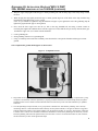
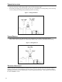
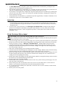
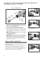
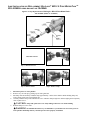
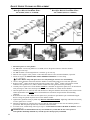
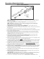
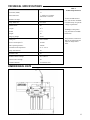
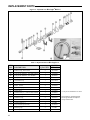
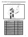
Models BIO 1.5 PWP Ballast 120v 50/60 Hz Ballast 230v 50/60Hz 10-0010B 10-0504A 375 Marcus Boulevard • Hauppauge, NY 11788 • USA 631.273.0500 • Fax: 631.273.0771 e-mail: [email protected] Extensive Product Information Available at: www.ultraviolet.com Document No. 98-1524A • June 2012 • ©2002-2012 Atlantic Ultraviolet Corporation ® TABLE OF CONTENTS SAFETY WARNINGS.....................................................................................................................................................3 SAFETY INSTRUCTIONS ............................................................................................................................................3 PRODUCT APPLICATION ...........................................................................................................................................4 CONSTRUCTION ............................................................................................................................................................4 PRINCIPLE OF OPERATION .............................................................................................................................................4 LIMITATION OF USE ......................................................................................................................................................4 WATER QUALITY ..........................................................................................................................................................4 INSTALLATION .............................................................................................................................................................5 LOCATION.....................................................................................................................................................................5 SADDLE VALVE INSTALLATION.......................................................................................................................................6 FAUCET INSTALLATION..................................................................................................................................................6 SYSTEM INSTALLATION .................................................................................................................................................7 GROUNDING KIT INSTALLATION: Bio-Logic ® BIO-1.5 Pure Water PackTM 230V 50/60HZ USING BALLAST NO.10-0504A .................................8-9 TUBING INSTALLATION................................................................................................................................................10 TUBING REMOVAL ......................................................................................................................................................10 TECHNICAL ASSISTANCE ..............................................................................................................................................10 MAINTENANCE ...........................................................................................................................................................11 INSPECTION ................................................................................................................................................................11 FILTER CARTRIDGE REPLACEMENT..............................................................................................................................11 LAMP INSTALLATION OR REPLACEMENT: Bio-Logic ® BIO-1.5 Pure Water PackTM 120V 50/60HZ USING BALLAST NO.10-0010B.................................. 12 DISPOSAL OF MERCURY ADDED LAMPS ......................................................................................................................12 LAMP INSTALLATION OR REPLACEMENT: Bio-Logic ® BIO-1.5 Pure Water PackTM 230V 50/60HZ USING BALLAST NO.10-0504A ..................................13 QUARTZ SLEEVE CLEANING OR REPLACEMENT ...........................................................................................................14 REPLACEMENT OF BROKEN QUARTZ SLEEVE ..............................................................................................................15 TROUBLESHOOTING ................................................................................................................................................16 TECHNICAL SPECIFICATIONS...............................................................................................................................17 DIMENSIONAL DATA.................................................................................................................................................17 REPLACEMENT PARTS .......................................................................................................................................18-19 Bio-Logic ® BIO-1.5 Ultraviolet Water Purifier ............................................................................................................18 Pure Water Pack TM ......................................................................................................................................................19 USER ASSISTANCE .....................................................................................................................................................20 WARRANTY..................................................................................................................................................................20 PATENT NOTICE ..........................................................................................................................................................20 These instructions generally describe the installation, operation and maintenance of the Bio-Logic ® Pure Water PackTM. Questions that are not specifically answered by these instructions should be directed to the Factory. Atlantic Ultraviolet Corporation takes all possible precautions when packaging equipment to prevent damage. Carefully inspect and report all damage upon receipt of product. Do not install damaged equipment. Follow all instructions on all labels and tags. Carefully inspect all packing materials before discarding to prevent the loss of accessories, mounting hardware, spare parts or instructions. The information and recommendations contained in this publication are based upon data collected by the Atlantic Ultraviolet Corporation® and are believed to be correct. However, no guarantee or warranty of any kind, expressed or implied, is made with respect to the information contained herein. Specifications and information are subject to change without notice. 2 SAFETY WARNINGS • • All personnel should be alerted to the potential hazards indicated by the product safety labeling on this unit. The following conventions are used to indicate and classify precautions in this manual and on product safety labeling. Failure to observe precautions could result in injury to people or damage to property. ! This is the safety alert symbol. It is used to alert you to potential personal injury hazards. Obey all safety messages that follow this symbol to avoid possible injury or death. Danger indicates an IMMINENTLY hazardous situation, which, if not avoided, WILL result in death or serious injury. Warning indicates a POTENTIALLY hazardous situation, which, if not avoided, COULD result in death or serious injury. Caution indicates a POTENTIALLY hazardous situation, which, if not avoided, MAY result in minor or moderate injury. Caution used without the safety alert symbol indicates a potentially hazardous situation, which, if not avoided, may result in property damage. This symbol/pictorial is used to identify an ELECTRICAL SHOCK or ELECTROCUTION hazard. This symbol/pictorial is used to identify an ULTRAVIOLET LIGHT hazard. • Product safety labels should be periodically inspected and cleaned, as necessary, to maintain good legibility. Always replace illegible safety labels. Contact factory to obtain replacement safety labels. SAFETY INSTRUCTIONS ! 1. 2. 3. 4. 5. 6. 7. 8. 9. 10. 11. 12. 13. 14. 15. 16. WARNING: To guard against injury, basic safety precautions should be observed, including the following: Read and follow ALL safety instructions. Do not use this system for other than its intended purpose, as described in these instructions. Do not alter the design or construction. Do not remove any labels or devices. ! DANGER: To prevent the risk of severe or fatal electrical shock, special precautions must be taken since water is present near electrical equipment. Always disconnect power before performing any service or maintenance ! WARNING: Avoid exposure to direct or strongly reflected germicidal ultraviolet rays. Germicidal ultraviolet rays are harmful to the eyes and skin. Check local public works department for plumbing codes. Follow all guidelines when installing the Pure Water Pack®. Intended for indoor use only. The system should be protected from the elements and from temperatures below freezing. Do not operate water purifier if lamp cable, lamp connection, power cord and/or plug are damaged, or if any other damage to the water purifier is visible or suspected. Electrical power supplied, to the system, MUST match power requirements listed on the system. Plug system into a properly installed, grounding type, receptacle that has Ground Fault Circuit Interrupter (GFCI) protection. ! CAUTION: Do not operate without proper electrical ground. Do not exceed maximum rated flow capacity. Do not exceed maximum operating pressure of 100 PSI. Read and follow all notices and warnings on the system. SAVE THESE INSTRUCTIONS. 3 PRODUCT APPLICATION CONSTRUCTION • • • • • • All filtration and disinfection components, of the Bio-Logic ® Pure Water PackTM, are conveniently mounted on a single, stainless steel, mounting bracket. The system is designed to mount on a vertical surface, a secure (stud or concrete) wall or a cabinet wall, by the system-mounting bracket. The faucet, supplied with the system, is a low lead, stainless steel faucet, with a hand operated, spring closed lever. The faucet can be locked in the “ON” position by pushing the lever up locking it against the spout. The water purifier's dual chamber heads are removable and may be rotated independently, which aids in the installation, maintenance or the retrofitting of an existing system. The water purifier's chamber, and chamber heads are electropolished and passivated type 316 stainless steel. Easy-off end caps allow for quick and easy lamp change, without disconnecting the system from the water supply or draining the purifier. No tools are required. PRINCIPLE OF OPERATION The Bio-Logic ® Pure Water PackTM filter system removes sediment, rust, scale, and particulates, while reducing tastes, odors, organic chemicals and turbidity. The Bio-Logic ® is the ultraviolet disinfection element of the Pure Water PackTM. The Bio-Logic ® design has been carefully conceived to provide adequate germicidal dosage throughout the disinfection chamber. The dosage, as it applies to ultraviolet disinfection, is a function of time, and the intensity, of ultraviolet radiation, to which the water is exposed. The exposure time, in seconds, is the total time it takes the water to flow through the disinfection chamber, exposing it to the germicidal lamp. Exposure time is related to the flow rate; the higher the flow rate, the lower the exposure time or the lower the flow rate, the higher the exposure time. The ultraviolet intensity is the amount of energy, per unit time, emitted by the germicidal lamp. The operation of the Bio-Logic ® is as follows: 1. Water enters the purifier and flows into the annular space between the quartz sleeve and the chamber wall. 2. Suspended microorganisms are exposed to the ultraviolet rays emitted by the germicidal lamp. 3. The LED indicator light, located on the ballast, provides visual indication of germicidal lamp operation. 4. Water leaving the purifier is instantly ready for use, no further contact time is required. LIMITATION OF USE The water purifier is intended for the use with visually clear water, not colored, cloudy or turbid. See “Water Quality” section below. The water purifier is NOT intended for the treatment of water that has an obvious contamination or intentional source, such as raw sewage; nor is the unit intended to convert wastewater to microbiologically safe drinking water. WATER QUALITY Water quality plays a major role in the transmission of germicidal ultraviolet rays. It is recommended that the water does not exceed the following maximum concentration levels: Table 1 - Maximum Concentration Levels Manganese: Total Suspended Solids: pH: Color: Hardness: Iron: 0.05mg/l 10 mg/l 6.5 - 9.5 None 6 GPG or 102.6 PPM 0.3 mg/l Effectively treating water with higher concentration levels than listed above can be accomplished, but may require added measures to improve water quality to treatable levels. If, for any reason, it is believed the ultraviolet transmission is not satisfactory, contact the factory. 4 Pure Water PackTM INSTALLATION LOCATION 1. The Pure Water PackTM is designed for “under the sink” installation. The system should be mounted vertically, to a secure wall or cabinet wall, which provides enough room to perform routine maintenance. This includes a minimum of 14-15/16 inches from the chamber end, to allow for removal of the lamp and/or quartz sleeve, a minimum of 6-inches on the backside of the water purifier, and a minimum of 2-inches free space under the filter housings, to allow for housing removal, when changing filter cartridges. Figure 1 - Bio-Logic ® Pure Water PackTM - Drinking Water System 2. 3. 4. 5. 6. The water purifier is intended for indoor use only. The water purifier should be protected from the elements and from temperatures below freezing. The ambient temperature, in the area surrounding the water purifier, should be between 33 F and 100 F. The water purifier must be connected to the cold water line only. The system should be located as close to the faucet as possible. ! CAUTION: As with any water handling device, the water purifier should be located in an area where any possible condensation or leakage from the water purifier, any purifier accessory and/or plumbing will not result in damage to the area surrounding the water purifier. For added protection, it is recommended that a suitable drain pan be installed under the purifier. The drain pan must be plumbed to an adequate, free flowing, drain to prevent water damage in the event of a leak. There are numerous leak detection/flood stop devices, available on the market today, designed to stop the flow of water, reducing the chance of water damage due to leakage. For more details regarding leak prevention and/or limiting damages due to leaks, please contact the factory. The system should be located within 5-feet of an electrical receptacle. The receptacle must be a properly installed, grounding type, receptacle that has Ground Fault Circuit Interrupter (GFCI) protection. 5 SADDLE VALVE INSTALLATION Check with the local public works department for plumbing codes. Follow all local plumbing codes when installing components of this system. The system comes supplied with a saddle valve and mounting hardware and is intended to be used on 3/8 inch to 1/2 inch copper tubing, and should be connected to the cold water line only. NOTE: This valve is not to be used on flex lines. 1. 2. 3. 4. 5. Shut off the cold-water supply valve under the sink or main valve for the house. Locate saddle valve in an accessible area. Slide the clamp over the copper tubing and tighten the bottom screw firmly to hold the clamp in position. Pierce the copper tubing by turning the “T” handle clockwise, until it is firmly seated. The valve is CLOSED in this position. Open the cold-water supply valve or main valve, check for any signs of leaks around valve connection. Install John Guest™ Tubing Connector on to the outlet of the saddle valve. Insert 1/4 inch OD tubing into the end of tubing connector see “Tubing Installation”. Figure 2 - Saddle Valve with Hardware CAUTION: DO NOT OPEN saddle valve until system is completely installed, doing so, at this time, will allow water to flow from the valve. FAUCET INSTALLATION Most sinks have an extra hole to mount additional faucets, sprayers or soap dispensers. If the sink does not have an additional hole, or it is being used by another attachment, a hole must be drilled in either the sink or countertop. The faucet stem requires a 1/2 inch diameter clearance hole for mounting; the chrome base plate will cover up a 1-1/2 inch diameter hole. Figure 3 - Faucet Mounting 6 FAUCET INSTALLATION CONT. 1. 2. ! 3. 4. 5. 6. Select faucet location. • Make sure the faucet is far enough away so not to interfere with the regular faucet or any other attachments. • If mounting faucet on the countertop, make certain the spout of the faucet will reach over the sink. • Check underneath the sink/countertop for any obstructions and for tool clearances required for mounting the faucet. • Make certain the faucet will fit flat against the sink/countertop, so 1-7/8 inch rubber washer will seal against chrome base plate and sink/countertop. Mark the center of the faucet location. CAUTION: To avoid possibly damaging sink and/or countertop, consult a qualified plumber or installer, special tools may be required for drilling porcelain, stainless steel, tile, etc. Using appropriate tools for particular sink or countertop construction, make a 1/2 inch diameter mounting hole. Install the 1-1/4 inch rubber washer onto the faucet, followed by the chrome base plate, and finally the 1-7/8 inch rubber washer. These parts must be installed onto the faucet before mounting the faucet to the sink or countertop. Install faucet into the mounting hole. From under the sink install the 1-3/4 inch washer, the locking washer and thread the 9/16 inch nut onto the faucet. Align the faucet to desired position, and firmly tighten the nut. Install John Guest™ Tubing Connector on to the inlet of the faucet. Insert 1/4 inch OD tubing into the end of tubing connector. See “Tubing Installation”. SYSTEM INSTALLATION 1. 2. 3. 4. 5. 6. ! 7. 8. Once a suitable location, for the system, has been chosen, mark the location of the mounting screws, using the holes on the mounting bracket as a template. Using appropriate fasteners, for the type wall chosen, mount the system through the holes of the mounting bracket. Tubing Connections: a. Run the tubing, connected to the saddle valve, to the inlet fitting of the sediment filter. b. Run the precut 24" tubing from the outlet of the carbon filter, to the inlet of the Bio-Logic ® water purifier. c. Run the tubing from the faucet to the outlet of the Bio-Logic ® water purifier. Measure, cut tubing. The tubing must be cut square, free of burrs and sharp edges. Leave enough slack in the tubing so the system can be easily removed, if necessary. Turn on the faucet, supplied by the Pure Water PackTM system. NOTE: Lifting the handle, of the faucet, will lock the faucet in the “ON” position, while holding the handle down the faucet is “ON”, the faucet well shut off when the handle is released. Slowly open the saddle valve, by turning the “T” handle counter-clockwise until fully open, and allow the system to fill with water. Once water begins to flow from the faucet, allow water to run for several minutes until it is clear with no air bubbles. Turn off the faucet and check the system for leaks. If leaks occur see “Troubleshooting” section. If no leaks occur, proceed to install the ultraviolet lamp. Unpack the lamp and ballast. While holding lamp end, carefully push lamp socket on. Carefully slide lamp straight into the quartz sleeve, without angling. Push the end cap on, over the static gland nut. Attach the ground connector to the grounding tab of the chamber. CAUTION: Lamp and quartz sleeve are easily damaged. Exercise care when handling. For 120v 50/60Hz operation using ballast no. 10-0010B, plug ballast into an approved Ground Fault Circuit Interrupt (GFCI) receptacle. Where a 2-prong or unprotected 3-prong receptacle is encountered, it must be replaced by a properly grounded Ground Fault Circuit Interrupt (GFCI) receptacle. Installation must be in accordance with the National Electrical Code and any local codes and ordinances by a qualified electrician. For 230v 50/60Hz operation using ballast no. 10-0504A, use Grounding Kit supplied (part no. 35-7300A) See Figure 12 Grounding Kit on Page 18. For 12v DC operation; The ballast must be wired to an adequate 12v DC source with appropriate gauge wire for the voltage and current. It is recommended that the ballast have a dedicated run to the 12v source, and protected by either a fuse or circuit breaker. • Always disconnect the battery(s), or other 12v source, before installation or performing any maintenance. • The ballast is supplied with a 6-foot, 2 wire, power cord and 5-foot lamp cord, the ballast must be located so the lamp is easily removed and does put any tension on the lamp, which could cause damage to the lamp and/or quartz sleeve. All installed wiring should be protected from heat, wear points (abrading) or mechanical stress. Secure ballast using the mounting tabs located on the ballast body. • Wire ballast power cord as follows; Brown wire - Positive (+) to protected (fuse or circuit breaker) 12v DC source. Blue wire - Negative (-) to suitable chassis ground. • If there are any questions or concerns regarding the installation and/or wiring of the 12v system, consult a qualified installer. It is recommended, when the carbon filter is new, to flush out the system thoroughly prior to use. Turn on the system's faucet and allow water to run for 10 minutes to flush the filter and system. 7 GROUNDING KIT INSTALLATION: BIO-LOGIC®BIO-1.5 PURE WATER PACKTM 230V 50/60HZ USING BALLAST NO.10-0504A 1. Ground Kits are shipped with each Bio-Logic ® BIO-1.5 Pure Water PackTM 230v 50/60Hz water purifier using ballast 10-0504A and is used to permanently connect a ground wire from the water purifier chamber to a known good ground. We recommend checking with local codes or a licensed electrician in your area to determine the best grounding point to attach the ground kit for your installation. An electrician can also measure the resistance between the water pipe and an electrical outlet ground to insure your ground selection is correct. PLACEMENT: Select a location that is visible as well as accessible. Connect the ground strap to a known good ground or a water pipe that is metallic, with no intervening plastic fittings between it and the power ground. INSTALLATION: Once a proper ground point has been determined, fasten the ground to the water purifier chamber as shown and described below. If you receive a 230v 50/60Hz water purifier, or ballast for a water purifier using ballast No. 10-0504A and a grounding kit is not present in the carton please contact the factory with your order information and we will send you the correct grounding kit for your application (35-7300A). TOOLS REQUIRED • • • 7/16" Wrench 10mm Wrench or Universal Pliers Continuity Tester Step 2 - Wrap Strap Tight Around Pipe Step 3 - Insert Bolt Through Both Copper Holes & Tighten using a 7/16" Wrench Step 5 - Locate grounding tab ! Step 6 -Slide grounding connector over grounding tab WARNING: To insure proper operation and safety of your water purifier, your unit must be grounded to a known good ground. 8 Step 4 • Insert Wire Into Hole & Install Bolt • Tighten Bolt against Wire using 10mm Wrench, Ensure all is Secure GROUNDING KIT INSTALLATION: BIO-LOGIC®BIO-1.5 PWP 230V 50/60HZ USING BALLAST NO.10-0504A (CONTINUED) 2. Wrap the copper strap tight around the pipe or metal grounding rod with the sharp edges of the strap facing towards the item. 3. While keeping the strap tightly around the pipe or metal ground, align one of the holes in the strap with the long threaded bolt, and tighten using a 7/16" wrench. (Note: As you continue to tighten the long threaded bolt it begins to press against the end of the grounding strap & tighten the grip around the pipe or metal ground) 4. Next, insert the bare copper wire into the eye hole in the long threaded bolt, and using a 10mm wrench or universal pliers tighten the small bolt down onto the copper wire. Ensure that the strap is securely fastened to the pipe and that the copper wire is in contact with the small bolt. 5. Locate grounding tab 6. Slide grounding connector over grounding tab. 7. Using a Continuity Tester insure that continuity exists between the water purifier chamber and the pipe or metal ground. Once completed the ground should appear as shown below. Figure 4 - Completed Ground 8. Plug ballast into an approved Ground Fault Circuit Interrupt (GFCI) receptacle. Where a 2-prong or unprotected 3-prong receptacle is encountered, it must be replaced by a properly grounded Ground Fault Circuit Interrupt (GFCI) receptacle. Installation must be in accordance with the National Electrical Code and any local codes and ordinances by a qualified electrician. 9. Once the plumbing hook ups are made, it is a good practice to disinfect the “downstream” plumbing. This is done by introducing chlorine or other disinfectant solution directly into the purifier chamber, a 100-ppm of chlorine is suggested. With the disinfectant solution in the purifier chamber, turn the ultraviolet purifier on. Open the “downstream” outlet until a chlorine odor is noticed. Close the outlet and allow the disinfectant to remain in the plumbing for at least three (3) hours. Flush the plumbing with ultraviolet purified water; allow the water to run for several minutes before use, this will allow the ultraviolet lamp to reach its full germicidal output. 9 TUBING INSTALLATION • • Measure and cut the tubing to desired length. Leave enough slack in the tubing so the system can be easily removed, if necessary. Cut the tubing square; remove all burrs and sharp edges. Insert tubing into fitting; push until it reaches the tube stop. Avoid kinking or stretching tubing. Check that tubing is secure; gently pull on tubing, tubing should not pull free from fitting. Figure 5 - Tubing Installation TUBING REMOVAL • • If the system has been in use, shut off supply valve and drain the system before removing any tubing. Push in collar, squarely against the face of the fitting. Holding collar in position, pull tubing from the fitting. Figure 6 - Tubing Removal TECHNICAL ASSISTANCE Atlantic Ultraviolet Corporation maintains a qualified team of application specialists that can provide any technical assistance, which maybe required during the use of this system. For any questions, concerns, or technical assistance, regarding this system or any of our other products, contact our application specialists. Contact options can be found in the “User Assistance” section. 10 MAINTENANCE • • • • • The Pure Water PackTM is designed to operate with a minimal amount of maintenance, providing the water quality does not exceed maximum concentration levels. Filter cartridge replacement is recommended every 12 months. Over time water pressure to the system faucet will drop, this is an indication that the filter cartridges are nearing the end of their service life. In poor quality water supplies filter cartridges may clog more rapidly, before the 12 months are up, reducing water pressure to the system faucet. In these cases, change filter cartridges immediately. Changing filter cartridges will restore normal water pressure. Lamp replacement is recommended every 10,000 hours of operation (approximately 12 months of continuous service). Cleaning of the quartz sleeve, when conditions warrant. INSPECTION 1. 2. Regularly inspect the water purifier to ensure that the germicidal lamp is still in operation. • An LED indicator light, located on the ballast, provides visual indication of germicidal lamp operation. This provides an indication of lamp operation and does not indicate the level of ultraviolet intensity or transmission through the water. To ensure proper system performance, of the Bio-Logic ® Pure Water PackTM, biological testing should be performed on a schedule recommended by local public health authorities. If, for any reason, there is trouble achieving proper performance, contact our application specialists. Contact options can be found in the “User Assistance” section. FILTER CARTRIDGE REPLACEMENT ! CAUTION: Never remove filter housings while the system is pressurized. NOTE: Place a small bucket under the system, when changing filter cartridges, to catch any water that may leak from system. 1. Disconnect and remove power to water purifier. 2. Shut off water supply to the system, by closing the supply valve. Open the system faucet and allow the system to drain. 3. Release the pressure in the filter housing, by pressing the red pressure release button, located on top of each filter housing. See Figure 2 on page 6 - Bio-Logic ® Pure Water PackTM - Drinking Water System for location. 4. Using the filter-housing wrench, loosen the filter housing by turning the housing clockwise. Remove the filter housing. Be careful, the filter housing will be full with water, adding to the weight of the filter housing. Be sure not to lose the large O-ring seal. 5. Drain water from filter housing, remove and discard old filter cartridge. 6. Clean the inside of the filter housing before installing the new filter cartridge. Wash the inside of the filter housing with soap and hot water, rinse out thoroughly. Make sure the O-ring is fully seated, in its groove. 7. Remove the wrapper from the new filter cartridge, and place into the filter housing. The filter cartridge will fit into the filter housing in either direction. The system uses 2 different filter cartridges. Be sure to install the correct cartridge into its corresponding filter housing. 8. Replace filter housing and cartridge onto filter head and firmly tighten, by turning filter housing counter-clockwise. Be careful not to cross thread the housing and filter head. 9. Repeat to replace the second filter cartridge. 10. Lift the handle, of the system faucet, and lock the faucet in the “ON” position. Slowly open the supply valve, and allow the system to fill with water. 11. When water begins to flow from the faucet, allow water to run for several minutes until it is clear with no air bubbles. Turn off the faucet and check between the filter housing and head for leaks. 12. It is recommended when installing a new carbon filter, to allow the water to run for 10 minutes to flush the filter and system prior to use. 13. Restore power to the water purifier. 11 LAMP INSTALLATION OR REPLACEMENT: BIO-LOGIC® BIO-1.5 PURE WATER PACKTM 120V 50/60HZ USING BALLAST NO. 10-0010B Figure 7 - Lamp Replacement Step 1 - Disconnect Power and Remove Ground Connector 1. 2. 3. 4. 5. Disconnect power to Pure Water PackTM, and remove ground connector from the Bio-Logic ® chamber. Remove easy-off end cap by pulling cap off static gland nut. Carefully withdraw lamp approximately 2" from chamber. While holding lamp end, remove lamp socket from exposed lamp end. Carefully withdraw lamp from chamber. Be sure to withdraw lamp straight out without angling until completely clear of quartz sleeve. ! 6. CAUTION: Lamp and quartz sleeve are easily damaged. Exercise care when handling. Reinstall lamp in reverse order. ! 7. Step 2 - Remove End-Cap WARNING: Germicidal ultraviolet rays are harmful to eyes and skin. Do not restore power to water purifier until lamp and both easy-off end caps have been properly reinstalled. Reattach the ground connector to the grounding tab of the chamber, and restore power to the system. Step 3 - Remove Socket DISPOSAL OF MERCURY ADDED LAMPS Germicidal ultraviolet lamps, like standard fluorescent lamps contain small amounts of mercury. Mercury added lamps should not be placed in the trash. Dispose of properly. For further information regarding the disposal and recycling of lamps containing mercury, along with Federal and State requirements visit http://www.lamprecycle.org. Product Data Sheets for germicidal ultraviolet lamps can be found in the “PDF Library for Ster-L-Ray ® Germicidal Ultraviolet Lamps” section of http://www.ultraviolet.com. Step 4 - Remove Lamp 12 LAMP INSTALLATION OR REPLACEMENT: BIO-LOGIC® BIO-1.5 PURE WATER PACKTM 230V 50/60HZ USING BALLAST NO.10-0504A Figure 8 - Lamp Replacement for Bio-Logic ® BIO-1.5 Pure Water PackTM 230v 50/60Hz (ballast no. 10-0504A) Disconnect Power 1. 2. 3. 4. Step 1 - Disconnect Power Step 2 - Remove End-Cap Step 3 - Remove Socket Step 4 - Remove Lamp Disconnect power to water purifier. Remove easy-off end cap by pulling cap off static gland nut. Pull lamp cord and carefully withdraw lamp approximately 2 inches from chamber. While holding lamp end, remove lamp socket from exposed lamp end. Carefully withdraw lamp from chamber. Be sure to withdraw lamp straight out without angling until completely clear of quartz sleeve. ! 5. CAUTION: Lamp and quartz sleeve are easily damaged. Exercise care when handling. Reinstall lamp in reverse order. ! WARNING: Germicidal ultraviolet rays are harmful to eyes and skin. Do not restore power to water purifier until lamp and easy-off end caps have been properly reinstalled. 13 QUARTZ SLEEVE CLEANING OR REPLACEMENT Figure 10 - Quartz Sleeve Cleaning or Replacement Bio-Logic ® BIO-1.5 Pure Water PackTM 120v 50/60Hz (ballast no. 10-0010B) Step 4 - Remove Gland Nuts Figure 11 - Quartz Sleeve Cleaning or Replacement Bio-Logic ® BIO-1.5 Pure Water PackTM 230v 50/60Hz (ballast no. 10-0504A) Step 5 - Remove Washer & O-Ring Step 6 - Remove Quartz Sleeve 1. Disconnect power to water purifier. • For 120v 60Hz version using ballast no. 10-0010B, remove the ground connector from the chamber, and then go to next step. • For 230v 50/60Hz version using ballast no. 10-0504A, go to next step. 2. Shut off water supply to water purifier via inlet and outlet shut off valves and drain chamber, if possible. 3. Follow the steps in “LAMP INSTALLATION OR REPLACEMENT” to remove lamp. ! CAUTION: Lamp and quartz sleeve are easily damaged. Exercise care when handling. 4. Unscrew static gland nuts from each end of the chamber. Avoid striking quartz sleeve with static gland nut. 5. Remove Teflon® washer and O-ring from both ends of quartz sleeve. Teflon® washer will sometimes remain within the static gland nut. If so, remove Teflon® washer from static gland nut before proceeding. 6. Carefully remove quartz sleeve from chamber. NOTE: It is advisable to support the quartz sleeve on the backside with your finger so that it does not drop to the bottom of the chamber as it slides into the chamber. 7. Once the quartz sleeve is removed, clean with alcohol or a detergent. Stubborn stains usually can be removed with a dilute hydrochloric acid. NOTE: Follow all manufacturer's instructions and precautions when handling chemicals. 8. Reassemble in reverse order. Make sure the quartz sleeve protrudes an equal distance past each threaded nipple. Be sure O-rings are placed on quartz sleeve before Teflon® washer. 9. Tighten static gland nuts firmly by hand only, DO NOT USE HAND TOOLS. Tightening with hand tools is likely to cause quartz sleeve to break. 10. When all connections are complete allow water to enter the water purifier at a low flow rate until the purifier is pressurized. With the purifier pressurized, it should be checked for leaks. 11. If no leaks occur, reinstall lamp, following the steps in “LAMP INSTALLATION OR REPLACEMENT” section. ! WARNING: Germicidal ultraviolet rays are harmful to eyes and skin. Do not restore power to water purifier until lamp and both easy-off end caps have been properly reinstalled. 14 REPLACEMENT OF BROKEN QUARTZ SLEEVE Figure 11 - Chamber Head Removal ! CAUTION: ! CAUTION: Considerable force may be required to pull purifier from the mounting clips. Broken Quartz is SHARP. It is recommended that protective goggles and gloves are worn when handling. 1. Follow the steps in “Quartz Sleeve Cleaning or Replacement” to remove lamp and quartz sleeve. Exercise extreme care when removing purifier. 2. Remove the tubing from the inlet and outlet fittings of the Bio-Logic ® Ultraviolet Water Purifier. See “Tubing Removal” for the proper method of removing the tubing. 3. Remove the water purifier from the mounting clips. Grasp the purifier chamber, and firmly pull each end free of the mounting clips. 4. Carefully remove as much of the broken quartz sleeve as possible, from each end of the chamber. 5. Remove chamber head clamp, by using a 7/16" wrench to loosen and remove the 1/4" nut from the head clamp. 6. Remove chamber head from the chamber. 7. Any broken pieces of the quartz sleeve can now be removed through the open end of the purifier chamber. Flush water through chamber being careful to remove all quartz fragments from the interior of the chamber. Carefully discard all pieces of the broken quartz sleeve. 8. Inspect the large O-ring used to seal the chamber and the chamber head. Make sure the O-ring is seated properly between the chamber head ring and the flare of the chamber head. 9. To reinstall the chamber head, push chamber head flange into the chamber until both flared ends, of the chamber and the head, mate against the O-ring. 10. Replace the head clamp around the flared ends of the head and chamber. Install the 1/4" nut and tighten, using a 7/16" wrench, until approximately 7/8" to 1" of the bolt protrudes past the nut. 11. Carefully insert quartz sleeve into chamber. NOTE: It is advisable to support the quartz sleeve with your finger to guide it through the opening in the threaded gland fitting. Center the quartz sleeve in the chamber, making sure the quartz sleeve protrudes an equal distance past each threaded gland fitting. 12. Reinstall O-rings, Teflon ® washers, and static gland nuts. Be sure O-rings are placed on quartz sleeve before Teflon® washer. Tighten static gland nuts firmly by hand only, DO NOT USE HAND TOOLS. Tightening with hand tools is likely to cause quartz sleeve to break. 13. Remount the water purifier to system-mounting bracket, by firmly pressing the purifier into the chamber brackets. 14. Reinstall the tubing; see “Tubing Installation” for the proper method of installing the tubing. Be sure that the tubing from the outlet of the carbon filter goes to the inlet of the water purifier, and the tubing from system faucet goes to the outlet of the water purifier. 15. Lift the handle, of the system faucet, and lock the faucet in the “ON” position. Slowly open the supply valve, and allow the system to fill with water. 16. When water begins to flow from the faucet, allow water to run for several minutes until it is clear with no air bubbles. Turn off the faucet and check the water purifier for leaks. ! WARNING: Germicidal ultraviolet rays are harmful to eyes and skin. Do not restore power to water purifier until lamp and both easy-off end caps have been properly reinstalled. 17. If no leaks occur, reinstall lamp by following the steps in “Lamp Installation or Replacement” section. 15 TROUBLESHOOTING ! WARNING: Always disconnect power to the water purifier before performing any service or maintenance. IMPORTANT: This unit is to be serviced ONLY by qualified, and appropriately licensed, personnel. Table 2 - Troubleshooting Problem Possible Cause Corrective Action Purifier not operating. No electrical power… Verify that the purifier is connected to a live power source. Cracked or broken Shut down purifier, drain, and replace quartz sleeve. quartz sleeve… See “Quartz Sleeve Cleaning or Replacement”. Quartz sleeve sealing O-ring (s) worn, damaged… Shut down purifier, drain, and remove static gland nut, replace sealing O-ring. See “Quartz Sleeve Cleaning or Replacement”. Poor, or loose, connections or fittings… Tighten suspect connection or John Guest™ fitting; or shut down purifier, drain, and remove fitting or connection. Clean threads; reapply thread sealing tape and reinstall. Water leaking from fitting. Tubing may not be installed properly… See “Tubing Installation” for the proper method for installing tubing. Water cloudy and/or has air bubbles. Air in system… Open system faucet, allow water to run, until water clears and has no air bubbles. Water contains black particles. New carbon filter cartridges contain activated carbon, in a powder form… Open system faucet; allow water to run, purging the carbon particles from the cartridge, until water is clear. Filters installed for longer than 12 months… Replace both filter cartridges. See “Filter Cartridge Replacement”. Water leaking into/from purifier. Water pressure dropped. Water quality poor, filters clogged… Poor purifier performance 16 Quartz sleeve fouled… Clean quartz sleeve, see “Quartz Sleeve Cleaning or Replacement”. Germicidal lamp output depreciating… Replace lamp, as it nears its end of life (EOL). See “Lamp Installation or Replacement”. Germicidal lamp not functioning… Replace lamp. See “Lamp Installation or Replacement”. Low input voltage… Verify input voltage to purifier. Change in water quality… Have water tested to confirm that it does not exceed maximum recommended concentration levels for use with this purifier. TECHNICAL SPECIFICATIONS MODEL: Pure Water PackTM Flow Rate (GPM): 1.5 Inlet\Outlet Size: 1 Number of Lamps: 1 Lamp Model No.: 05-1366-R Quartz Sleeve: Yes Length: 14 1/2" Width: 5 3 /4" Height: 18" Shipping Weight: 18 Lbs Voltage: 120V 50/60Hz Power Consumption: 14 Watts Max Operating Pressure: 100 PSI Ambient Room Temperature: 33° F - 100° F Lamp Out Indicator Yes Installation Kit Yes Sediment Filter Cartridge Yes, 5 Micron Carbon Filter Cartridge Yes Chamber Material 316 Stainless Steel Table 3 Technical Specifications /4" Tubing to 3/8" MNPT John GuestTM Connector 220v 50/60Hz and 12v DC units are also available. Consult Factory for specific voltage requirements. Wattage is lamp watts only, and does not include ballast loss. All specifications, dimensional data, etc are approximate and subject to change without notice. DIMENSIONAL DATA 17 REPLACEMENT PARTS Figure 12 - Exploded View Bio-Logic ® BIO-1.5 Table 4 - Replacement Parts Bio-Logic ® 1.5 ITEM NO. QUANTITY MODEL BIO-1.5 Rubber O-ring, Static Gland 2 00-1108B 2A Lamp Socket & Ballast, 120v 60Hz (shown) 1 10-0010B 2B Lamp Socket & Ballast, 230v 50/60Hz 1 10-0504A* 2C Lamp Socket & Ballast, 12v DC 1 10-1201A* 3 Germicidal Lamp 1 05-1366-R 4 Static Gland Nut 2 25-1492D 5 Teflon® Washer 2 25-3023A 6 Rubber O-ring, Quartz Sleeve 2 00-1023A 7 Quartz Sleeve 1 15-1700A 8 Chamber Head, 2 ½" with Ground Terminal 1 25-4506A 9 Chamber Clamp 2 25-6009 10 Chamber O-ring 2 00-0250A 11 Chamber Tube 1 25-6004A1 12 Chamber Head, 2 ½" 1 25-6042 13 Easy-Off End Cap (no hole) 1 25-1493A 14 Mounting Clip 2 27-0045 15 Grounding Kit for ballast no. 10-0504A* 1 35-7300A 1 18 DESCRIPTION * Lamp Socket and Ballast not shown All specifications, dimensional data, etc are approximate and subject to change without notice. REPLACEMENT PARTS Figure 13 - Exploded View Bio-Logic ® BIO-1.5 Pure Water PackTM Table 5 - Replacement Parts Bio-Logic ® Pure Water PackTM ITEM NO 1 DESCRIPTION QUANTITY Pure Water PackTM Filter Bracket 1 25-9132A 2A Bio-Logic® 1.5 120v 50/60Hz 1 25-9125A1 2B Bio-Logic® 1.5 230v 50/60Hz 1 25-9126A1 3 Screw, 8-32 x ½" Long 2 50-1394 4 Nut, Hex, 8-32 2 50-1180 5 Filter Housing, 10" w/Pressure Relief Valve 2 25-4507 6 Screw, 10-16 x ¾" Long 8 50-0096 7 Filter Cartridge, 5 Micron, Pleated 1 25-4508 8 Filter Cartridge, Carbon 1 25-4509 9 Male Connector ¼"x3/8" NPTF John Guest™ 4 25-4513 10 Pipe Nipple, 3/8"x1-½" Long PVC 1 25-4510 11 Tubing ¼" OD x 24" Long 1 25-4515 12 Saddle Valve fits 3/8" - ½" Copper Tubing 1 25-4511 13 Faucet, Long Reach Spout 1 25-4512 14 Tap Adaptor, ¼"x7/16"-24UNS John Guest™ 2 25-4514 15 Tubing, ¼" OD, White Plastic 15' 25-4516 16 Wrench, Filter Housing Sump 1 25-8000 17 Description O-Ring - Filter Cartridge 2 00-0330 All specifications, dimensional data, etc are approximate and subject to change without notice. 19 USER ASSISTANCE Atlantic Ultraviolet Corporation Please read and become familiar 375 Marcus Boulevard with the contents of this manual Hauppauge, New York, 11788 before installing or using this unit. If after reading the manual you still Tel: 631.273.0500 have questions, or concerns, Fax: 631.273.0771 regarding the installation or use of this unit, contact our offices, weekdays between 8:30 am and 5:00 pm E-mail: [email protected] Website: www.ultraviolet.com Eastern time, at: Please REGISTER your product immediately - you can do this in a number of ways. Go online to Ultraviolet.com and on the bottom left of each page either click on “Fill out Warranty Reg. Form on-line!” complete and hit submit or click on “Download a PDF of the Warranty Reg. card” which you can print, fill out and mail in. If you prefer to register over the telephone please call 631-273-0500. Atlantic Ultraviolet Corporation takes all possible precautions when packaging equipment to prevent damage. Carefully inspect and report all damage. Do not install damaged equipment. Follow all instructions on any labels or tags. Carefully inspect all packing materials before discarding to prevent the loss of accessories, mounting hardware, spare parts or instructions. For your convenience, record the following information below. The model and serial number can be found on a label located on the Pure Water PackTM. Keep this manual, along with proof of purchase, handy when contacting our offices. Atlantic Ultraviolet Corporation makes every effort to ensure that the Bio-Logic ® Pure Water PackTM is a product of superior quality and workmanship. This manual describes the installation, operation and maintenance of the Bio-Logic ® Pure Water PackTM. Purchased From: Date: Model: Serial No.: WARRANTY We warrant that this product will be free from defects in material and workmanship for a period of one year from the date of shipment thereof or the product's total rated life, whichever first occurs. Within the warranty period we shall repair or replace such products, which are returned to us with shipping charges prepaid, and which are determined by us to be defective. This warranty will not apply to any product, which has been subjected to misuse, negligence, or accident; or misapplied; or modified; or repaired by unauthorized persons; or improperly installed. The buyer shall inspect the product promptly after receipt and shall notify us at our main office in writing of claims, including claims of breach of warranty, within thirty (30) days after the buyer discovers or should have discovered the facts upon which the claim is based. Failure of the buyer to give written notice of a claim within the time period shall be deemed to be a waiver of such claim. The provisions of the above warranty are our sole obligation and exclude all other remedies or warranties, expressed or implied, including warranties of merchantability and fitness for a particular purpose, whether or not purposes or specifications are described herein. We further disclaim any responsibility whatsoever to the customer, or to any person, for injury to person, damage to, or loss of property or value caused by any product which has been subjected to misuse, negligence, accident; or modified or repaired by unauthorized persons; or improperly installed. Under no circumstances shall the Atlantic Ultraviolet Corporation be liable for any incidental, consequential or special damages, losses or expenses arising from the contract for this product, or in connection with the use of, or inability to use, our product for any purpose whatsoever. PATENT NOTICE No attempt has been made to determine the patent status of applications illustrated or described in this publication. Inclusion in this publication of any design or method of use, which may be patented, is not to be construed as promoting or sanctioning unauthorized use. 20