1
ELAN
HOME
C2
SYSTEMS
INSTALLATION MANUAL
Preface
Purpose of This Manual
This manual provides step-by-step installation instructions and connection examples, along with
basic user information for installation and ongoing use of the C2 Communications Controller. This
manual is written for the installer of this equipment.
Organization
The following information is contained in this manual:
Safety Information
Provides a comprehensive list of safety practices and
procedures allowing for the safe installation and operation of the C2 Communications Controller.
Introduction
Provides a description of C2 Communications Controller
front panel controls and indicators, special features, an
explanation & description of the Quick Reference Telephone Features Guide and front panel adjustments and
switch settings.
C2 System Design
Overview
Provides a system design application overview of the C2
Communications Controller when used in the following
applications; Stand-Alone, S66A, S86A/P, S128P, trigger
input and outputs and relay design.
C2 System Connections
Overview
Provides C2 Communications Controller system connections to trigger output connections, volume control
connections, door station connections, relay connections
and telephone connections from the phone company and
to the inside phones.
Troubleshooting
Provides a troubleshooting table to help fix common
discrepancies that maybe associated with the C2 Communications Controller.
Specifications
Appendix A provides equipment specifications for the C2
Communications Controller.
Door Stations
Appendix B provides installation instructions for mounting the ELAN DSF3, DSC3 and DSS3 Door Stations.
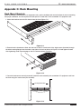
Rack Mounting
Appendix C provides installation instructions for mounting the C2 Communications Controller.
© ELAN Home Systems 2009 • All rights reserved.
Page 1
C2
INSTALLATION MANUAL
ELAN
HOME
SYSTEMS
Safety Information
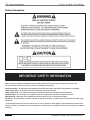
IMPORTANT SAFETY INFORMATION
When using your telephone equipment, basic safety precautions should always be followed to reduce the
risk of fire, electric shock and injury to persons, including the following:
Read Information—All the safety and operating information should be read before the appliance is operated.
Follow Information—All operating and use information should be followed.
Retain Information—The safety and operating information should be retained for future reference.
Heed Warnings—All warnings on the appliance and in the operating instructions should be heeded.
Wall Mounting—Mounting of this appliance should be done only by an authorized installer.
Ventilation—The appliances should be situated so that their location or position does not interfere with their proper
ventilation.
-These appliances should never be placed near or over a radiator or heat register. These appliances should not be
placed in a built-in installation such as a bookcase or cabinet that may impede the flow of air through the ventilation
openings.
Page 2
© ELAN Home Systems 2009 • All rights reserved.
ELAN
HOME
SYSTEMS
C2
INSTALLATION MANUAL
Water and Moisture—To reduce the risk of electric shock or fire, these appliances should not be used near water-––for example, near a bathtub, washbowl, kitchen sink, laundry tub, in a wet basement, or near a swimming pool.
Power Cord Protection—Protect the power cord from being walked on or pinched particularly at plugs, convenience receptacles and the point where they exit from the apparatus.
Telephones—Avoid using a telephone (other than a cordless type) during an electrical storm. There may be a
remote risk of electrical shock from lightning. Do not use a telephone to report a gas leak if the leak is in the vicinity
of the ELAN electronic equipment because of risk of fire or explosion.
Cleaning—Unplug the apparatus from the power outlet before cleaning. Use only a dry cloth to clean the apparatus.
Power Lines—An outdoor antenna should be located away from power lines. When installing an outside antenna
system, extreme care should be taken to avoid touching power lines or circuits, as contact with them may be fatal.
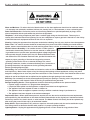
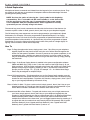
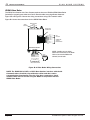
Outdoor Antenna Grounding—If an outside antenna or cable system is
connected to these audio products, be sure the antenna or cable system
is grounded so as to provide some protection against voltage surges and
built-up static charges. Section 810 of the U.S. National Electrical Code,
and Section 54 of the Canadian Electrical Code, provide information with
respect to proper grounding of the mast and supporting structure,
grounding of the lead-in wire to an antenna discharge unit, size of
grounding conductors, location of antenna-discharge unit, connection to
grounding electrodes, and requirements for the grounding electrode.
See the grounding diagram (right).
Overloading—Do not overload wall outlets and extension cords, as this could result in fire or electric shock. Object
and Liquid Entry—Never insert objects of any kind through the openings of these appliances, as they may touch
dangerous voltage points or short-out parts that could result in a fire or electric shock. Care should be taken so that
objects do not fall and liquids are not spilled into the appliance through openings in the enclosure.
Servicing—Do not attempt to service these appliances yourself, as opening or removing covers may expose you to
dangerous voltage or other hazards. Refer all servicing to qualified service personnel.
Damage Requiring Service—These appliances should be serviced by qualified service personnel when:
• A power supply connection or a plug has been damaged or
• If liquid has been spilled into the appliance or objects have fallen into the appliance or
• The appliance has been exposed to water or moisture or
• The appliance does not appear to operate normally or exhibits a marked change in performance or
• The appliance has been dropped or the enclosure damaged.
Replacement Parts—When replacement parts are required, be sure the service technician has used replacement
parts specified by the manufacturer or that have the same characteristics as the original part. Unauthorized substitutions may result in fire, electric shock, or other hazards. The Master Control Unit battery should be replaced only
after turning the power off and only by an authorized installer.
Safety Check—Upon completion of any service or repairs to this audio product, ask the service technician to perform safety checks to determine that the audio product is in proper operating condition.
Lightning Storms—Unplug this apparatus during lightning storms or when unused for long periods of time.
© ELAN Home Systems 2009 • All rights reserved.
Page 3
C2
INSTALLATION MANUAL
ELAN
HOME
SYSTEMS
Attachments and Accessories—Use only attachments/accessories specified by the manufacturer.
Cart, Stand, Tripod, Bracket or Table—Use only with a cart, stand, tripod, bracket or table specified by the manufacturer, or sold with the apparatus. When a cart is used, use caution when moving the cart/apparatus combination
to avoid injury from tip over.
Disconnect Device—Where the mains plug or an appliance coupler is used as the disconnect device, the disconnect device shall remain operable.
Gas Leak—Do not use the telephone to report a as leak in the vicinity of the leak.
Caution—To reduce the risk of fire, use only No. 26 AWG or larger telecommunication line cord.
SAVE THESE INSTRUCTIONS
IMPORTANTES MESURES DE SÉCURITÉ
Certaines mesures de sécurité doivent être prises pendant l’utilisation de matérial téléphonique afin de réduire les
risques d’incendie, de choc électrique et de blessures. En voici quelquesunes:
Ne pas utiliser l’appareil près de l’eau, p.ex., près d’une baignoire, d’un lavabo, d’un évier de cuisine, d’un bac à
laver, dans un sous-sol humide ou près d’une piscine.
Éviter d’utiliser le téléphone (sauf s’il s’agit d’un appareil sans fil) pendant un orage électrique. Ceci peut présenter
un risque de choc électrique causé par la foudre.
Ne pas utiliser l’appareil téléphonique pour signaler une fuite de gaz s’il est situé près de la fuite
il convient que l’aération ne soit pas gênée par l’obstruction des ouvertures d’aération par des objets tels que journaux, nappes, rideaux, etc.;
il convient de ne pas place sur l’appareil des source de flammes nues, telles que des bougies allumées;
que l’appareil ne doit pas être exposè á des ègouttements d’eau ou des èclaboussures et de plus u’aucun objet
rempli de liquide tel que des vases ne doit être placé sur l’appareil.
Un avertissment qu’un appareil de construction de CLASSE l doit être connecté à un socle du réseau d’alimentation
muni d’une connexion à la terre de protection.
lorsque la prise du RÉSEAU D’ALIMENTATION ou une prise placée sur l’appareil est utilisèe comme dispositif de
déconnexion, ce dispositif doit demeuré aisément accessible;
ATTENTION - Pour réduire les rusques d’incendies, utiliser uniquement des conducteurs de télécommunications 26
AWG au de sectioin supérleure.
CONSERVER CES INSTRUCTIONS
This product meets the applicable Industry Canada technical specifications.
IMPORTANT USER INFORMATION
The ELAN Home Systems C2 Communications Controller complies with Part 68 of the FCC rules and the requirements adopted by the ACTA. On the bottom side of this equipment is a label that contains, among other information, a product identifier in the format US:AAAEQ##TXXXX. If requested, this number must be provided to the telephone company.
ACTA-FCC Registration Number: US: 5J7MA07AC2
Industry Canada Registration Number: 2488-5235A
Ringer Equivalence Number (REN): 0.7A
The REN is used to determine the number of devices that may be connected to a telephone line. Excessive RENs
on a telephone line may result in the devices not ringing in response to an incoming call. In most but not all areas,
the sum of RENs should not exceed five (5.0). To be certain of the number of devices that may be connected to a
line, as determined by the total RENs, contact the local telephone company. For products approved after July 23,
2001, the REN for this product is. part of the product identifier that has the format US:AAAEQ##TXXXX. The digits
represented by ## are the REN without a decimal point (e.g., 03 is a REN of 0.3). For earlier products, the REN is
separately shown on the label.
Page 4
© ELAN Home Systems 2009 • All rights reserved.
ELAN
HOME
SYSTEMS
C2
INSTALLATION MANUAL
If your telephone equipment causes harm to the telephone network, the telephone company may discontinue your
service temporarily. If possible, they will notify you in advance. But, if advance notice isn’t practical, you will be notified as soon as possible. You will be notified of your right to file a complaint with the FCC. Connection to party line
service is subject to state tariffs. Contact the state public utility commission, public service commission or corporation commission for information.
If your home has specially wired alarm equipment connected to the telephone line, ensure the installation of this
[equipment ID] does not disable your alarm equipment. If you have questions about what will disable alarm equipment, consult your telephone company or a qualified installer. Your telephone company may make changes in its
facilities, equipment, operations, or procedures that could affect the proper functioning of your equipment. If they
do, you will be notified in advance to give you an opportunity to maintain uninterrupted telephone service. If you
experience trouble with this telephone equipment, please contact ELAN TECHNICAL SUPPORT at 1-800-622-3526
for information on obtaining service or repairs. The telephone company may ask that you disconnect this equipment
from the network until the problem has been corrected or until you are sure the equipment is not malfunctioning.
If the telephone features are not functioning or are malfunctioning, switch off the C2 Communications Controller
(located on the rear panel). This will directly connect the telephone line with all the telephones connected to the
package. Contact your dealer for repairs.
This equipment may not be used on coin service provided by the telephone company. Connection of party lines is
subject to state tariffs. (Contact your state public utility commission for information).
DISCLAIMER:
The ELAN C2 Communications Controller is an advanced design capable of interfacing with most telecommunication devices and central office switches. It has been thoroughly tested and should work satisfactorily with most telephone equipment. However, ELAN in no way represents, guarantees, or claims that the ELAN C2 Communications
Controller will achieve 100% functionality with every manufacturer’s telephone equipment or with every central
office feature.
ELAN Home Systems strongly recommends the use of a quality in-line Telephone Surge Suppressor such as the
Z•POWER Power Controller or TH31SRG surge Protection Hub. This device should be installed between the incoming telephone service line and the C2’s TELCO IN jack. If your installer has not installed such a device, please insist
that they do so. For additional protection on large wiring networks, surge suppression can also be added in series
with the C2’s PHONE OUT jack, protecting your house network and C2 from surge in both directions.Although the
installation of telephone line surge suppression is an important precautionary measure to take in protecting your
C2 from surge-related damage, it does not completely eliminate the possibility of surges entering into the system
through the telco line due to near or direct lightning strikes. ELAN Home Systems does not warranty this, or any
product against surge-related damage; nor does this warning imply that, if surge protection is installed and the unit
is subsequently damaged by surge, ELAN Home Systems would repair or replace the unit under warranty. Please
consult the warranty policy of the surge protection device you are installing for information on product repair/
replacement in the event of surge-related damage.
© ELAN Home Systems 2009 • All rights reserved.
Page 5
C2
INSTALLATION MANUAL
Page 6
ELAN
HOME
SYSTEMS
© ELAN Home Systems 2009 • All rights reserved.
ELAN
HOME
SYSTEMS
C2
INSTALLATION MANUAL
Table of Contents
Purpose of This Manual ...................................................................................................................... 1
Organization .......................................................................................................................................... 1
Safety Information ............................................................................................................................... 2
Chapter 1: Introduction
Introduction ........................................................................................................................................... 11
A Better Intercom ............................................................................................................................ 11
A Great Door System ...................................................................................................................... 11
Step-Saving Convenience .............................................................................................................. 11
Intuitive Operation ........................................................................................................................... 11
Automation In Mind ......................................................................................................................... 12
Bulletproof Design ........................................................................................................................... 12
The C2 and Your Phone Line ............................................................................................................... 12
Where Do You Install It? ................................................................................................................. 12
Features ........................................................................................................................................... 12
Paging .............................................................................................................................................. 12
Phone-to-Phone Intercom .............................................................................................................. 12
Music-On-Hold ................................................................................................................................ 12
Door Station Communication & Chimes ........................................................................................ 12
Selectable Door Chimes ................................................................................................................. 13
Home Automation ........................................................................................................................... 13
Telemute .......................................................................................................................................... 13
Music Mute ...................................................................................................................................... 13
On Hold Alert ................................................................................................................................... 13
Off Hook Alert .................................................................................................................................. 13
System Bypass ................................................................................................................................ 13
Quick Reference Telephone Features Guide ....................................................................................... 14
A Quick Explanation ........................................................................................................................ 15
How To ............................................................................................................................................. 15
Fax Machines, Modems, and Caller ID Boxes .............................................................................. 16
Paging .............................................................................................................................................. 16
Incoming Calls While Paging .......................................................................................................... 17
Paging With A Caller On Line ......................................................................................................... 17
Incoming Calls While Using the Door Station Assembly .............................................................. 17
Panel Functions .................................................................................................................................... 18
Front ................................................................................................................................................ 18
Front Panel LED Description .......................................................................................................... 19
Rear ................................................................................................................................................. 20
Front Panel Adjustments ................................................................................................................ 21
C2 Front Panel DIP Switch Settings .................................................................................................... 22
Chapter 2: C2 System Design Overview
Stand-Alone Stereo System Application ............................................................................................ 23
S66A Design Application ..................................................................................................................... 24
S86A Design Application ..................................................................................................................... 25
S128P Application ................................................................................................................................ 26
Trigger Input Design Application ......................................................................................................... 27
© ELAN Home Systems 2009 • All rights reserved.
Page 7
C2
INSTALLATION MANUAL
ELAN
HOME
SYSTEMS
Relay Design Application .................................................................................................................... 28
Chapter 3: C2 System Connections Overview
System Control .................................................................................................................................... 29
C2 Rear Panel Connections ............................................................................................................... 29
C2 to VMO or VSO Volume Controls ............................................................................................. 29
C2 to Electronic Volume Control ................................................................................................... 29
C2 to PVSE Electronic Volume Control Precision Panel .............................................................. 30
C2 Trigger Outputs ......................................................................................................................... 31
C2 Relays ........................................................................................................................................ 32
C2 To Incoming CO & Phones ....................................................................................................... 33
C2 to Door Station Connections .................................................................................................... 34
C2 to Trigger Inputs ........................................................................................................................ 35
Typical Telephone Service Connections .............................................................................................. 36
Connecting Telephone Service & Telephone Surge Protection to the System ........................... 36
Connecting Telephone Extensions to the TH48 Telephone Expansion Hub ............................... 37
New Construction ........................................................................................................................... 38
Retrofit ............................................................................................................................................. 39
Connecting The C2 To A Multi-Line Telephone system ................................................................ 40
Digital Subscriber Line (DSL) ......................................................................................................... 41
DSL Filters ....................................................................................................................................... 41
Standalone Connections (Without an ELAN Multi-Room Controller) ................................................. 42
Pre-Amp/Amp ................................................................................................................................. 42
Receiver Based System ................................................................................................................. 42
Stereo Receiver - Tape Loop ......................................................................................................... 43
Paging & Door Chime Using Two Independent Stereo Systems ................................................. 44
C2 Trigger Outputs to SIM2 Sensor Integration Module .............................................................. 45
ELAN Multi-Room Controller-Based Connections .............................................................................. 46
C2 to S66A Connections ............................................................................................................... 46
C2 To S86A ..................................................................................................................................... 47
S86A MOH/Page Trigger Input ...................................................................................................... 47
C2 to S86A Multi-Chassis Connections ........................................................................................ 48
S86A Sense Trigger Inputs ............................................................................................................ 48
C2 To S128P ................................................................................................................................... 49
S128P MOH/Page Trigger Input .................................................................................................... 49
C2 to S128P Multi-Chassis Connections .......................................................................................48
S128P Sense Trigger Inputs ........................................................................................................... 48
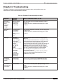
Chapter 4: Troubleshooting
C2 Troubleshooting Procedures ........................................................................................................... 51
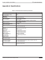
Appendix A: Specifications
C2 Communications Controller Specifications .................................................................................... 57
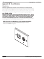
Appendix B: Door Stations
Introduction ........................................................................................................................................... 58
Door Stations Models ..................................................................................................................... 58
Specifications .................................................................................................................................. 59
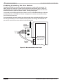
PreWiring & Installing The Door Stations ....................................................................................... 59
Page 8
© ELAN Home Systems 2009 • All rights reserved.
ELAN
HOME
SYSTEMS
C2
INSTALLATION MANUAL
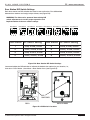
Door Station DIP Switch Settings ................................................................................................. 60
VBRM Video Balun .......................................................................................................................... 61
Non VBRM Applications ................................................................................................................. 62
DSF3 & DSC3 Installation ............................................................................................................... 63
DSC3 Doorbell Button Installation ................................................................................................. 64
DSS3 Installation ............................................................................................................................. 64
Appendix C: Rack Mounting
C2 Communications Controller Mounting Specifications .................................................................. 66
Limited Warranty ........................................................................................................................... Back Page
© ELAN Home Systems 2009 • All rights reserved.
Page 9
C2
INSTALLATION MANUAL
ELAN
HOME
SYSTEMS
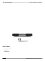
Items in package:
• C2 Communication Controller
• Rack Mount Brackets
• Power Cord
• Installation Manual
Page 10
© ELAN Home Systems 2009 • All rights reserved.
ELAN
HOME
SYSTEMS
C2
INSTALLATION MANUAL
Chapter 1: Introduction
Introduction
With the C2 Communication Controller, your multi-room audio system will be transformed
into a whole-house communications network. This stand-alone component integrates intercom,
telephone and home automation features with your existing audio system to seamlessly
create an environment of whole house communication and control.
A Better Intercom
With the C2, your audio system becomes a high-fidelity intercom system that is simple to
use. Page family members from any phone in your home. Hear clean, clear voice communications
via ELAN in-wall or in-ceiling speakers as the music mutes automatically. To answer a
page, simply pick up the nearest phone. No unsightly wall units to contend with - just reliable,
high-fidelity voice and music. You’ll use it every day and wonder “how did I live without this
before?”
A Great Door System
In larger homes, hearing a doorbell and then answering it is no easy task. The C2 is
designed to distribute up to ten different door chimes through in-wall or in-ceiling speakers,
alerting you to a visitor at any door entrance. With the DSS3, DSF3 or DSC3 Door Station
packages (optional), two-way communications and door latch control to any eight dwelling
entrances is a “touch-tone” away. Simply pick up the phone to query a visitor or unlock a door.
Step-Saving Convenience
Park an incoming call while you take it on another phone. When you page, callers are
automatically put on hold and entertained with the C2’s “Music-On-Hold” feature. If you
take a call in a room where music from the in-wall speakers is too loud––simply mute the
speaker audio from your phone. The C2 will alert you with tones through the audio system
if you inadvertently leave a caller on hold too long or if the phone receiver is left off hook.
Intuitive Operation
Phone feature commands are simple and intuitive. Press the pound sign (#), followed by
simple, easy to remember feature keys like “P” (7) for Page, “H” (4) for placing a caller on Hold,
“D” (3) for talking through the Doorspeaker or “M” (6) for Muting the audio system music for
that call.
Automation In Mind
With its relay control circuitry, the C2 can also provide control of home automation
amenities such as lighting, drapes, outside gates, even security systems. Home automation
commands, such as the opening of drapes and turning lights on or off are easily executed via
the telephone keypad. Nothing could be more simple or more elegant.
Bulletproof Design
Enhanced ESD protection, transient voltage surge protection, and phone-line conditioning
circuitry guarantee years of enjoyment from your C2. A high-output door speaker amplifier
and sensitive door microphone ensure superior two-way door communications.
© ELAN Home Systems 2009 • All rights reserved.
Page 11
C2
ELAN
INSTALLATION MANUAL
HOME
SYSTEMS
The C2 and Your Phone Line
Where Do You Install It?
The C2 Controller installs on your phone line before all the telephones. This installation
assures that you will be able to utilize the C2’s telephone and intercom features from any
phone in your home. The C2 is typically installed close to the home’s whole-house audio
system or stereo system components. The C2 provides communications features for up to
two separate phone lines from your local telephone provider.
The best thing about the C2 Communications Controller is that it does not require special
or proprietary phones. Any touch-tone phone, including cordless, are all that is required for
convenient, easy to use intercom and call features!
Features
Paging
The C2’s “Page” feature makes communicating to all rooms in your home as easy as
picking up a phone. The C2’s page audio is heard through the same speakers that provide
music throughout your home.
Phone-to-Phone Intercom
After paging a family member, a room-to-room phone conversation can be conducted without
being heard over the in-wall speakers when the second user picks up a handset on the same line.
Music-On-Hold
Callers who are placed on hold enjoy music via the C2’s “Music-On-Hold” feature
(dedicated Music-On-Hold source required).
Door Station Communication & Chimes
The C2 provides two-way communication and door chimes for up to eight dwelling
entrances. With the addition of an ELAN DSC3, DSS3 or DSF3 Doorstation Assembly, you
can conduct two-way conversations with any door station via your telephone. When someone
presses the ELAN doorbell button, a chime will sound over the speakers in every room. There
are ten selectable door chimes to choose from, so you can immediately identify which
entrance has a visitor.
Selectable Door Chimes
The C2 features 10 user-selectable door chimes that let you differentiate between door
stations. Unique chimes, such as sleigh bells, a fog horn and even a barking dog make for fun
door announcements that can easily be changed for the occasion. Here are the available door
chimes:
•
•
•
•
•
•
•
•
•
•
01
02
03
04
05
06
07
08
09
10
Page 12
-
8-Note Bells (Door Station
4-Note Bells (Door Station
3-Note Bells (Door Station
2-Note Bells (Door Station
“Ding-Dong”
Fog Horn
Mean Dog Barking
Sleigh Bells
Ping
Sonar Blip
1
2
3
4
default)
default)
default)
default)
© ELAN Home Systems 2009 • All rights reserved.
ELAN
HOME
SYSTEMS
C2
INSTALLATION MANUAL
Home Automation
From your telephone, you can activate up to four relays that can be configured to trigger home
automation controls such as lighting, draperies, security systems or garage door openers.
Telemute
The C2’s “Telemute” feature automatically mutes the music throughout your home
whenever a page or door chime is activated or whenever the phone rings. The music will come
back on once the page or door chime has ended or when you pick up the phone to answer
the call.
Music Mute
The C2 mutes the music when you press #, M. The tunes come back when you hang up.
On Hold Alert
When you place a caller on hold, one minute after the phone is placed “on-hook” the C2 will transmit a single beep
over the speakers at 5 second intervals, alerting you that the caller is still on hold.
Off Hook Alert
If any phone is left off hook, after two minutes the C2 will transmit a double beep over all the peakers at 5 second
intervals alerting you that the phone is off the hook.
System Bypass
This feature allows you to override all C2 phone features and enjoy call services provided
by your local phone company, bank or credit card company, etc.
When you want to call someone, simply pick up the phone and start dialing! It’s that simple.
It is not necessary to dial #, 9 before dialing out. There are, however, certain instances where
this feature will come in handy:
• When dialing out to an automated service that requires the use of “#” to access
services and enter information (i.e., banking by phone or credit card company).
© ELAN Home Systems 2009 • All rights reserved.
Page 13
ELAN HOME SYSTEMS
C2
QUICK REFERENCE GUIDE FOR COM2
ELAN
ARTWORKMANUAL
ELAN P/N: 9900870 REVA
INSTALLATION
ECN:
DATE: 01/09/09
HOME
SYSTEMS
Quick Reference Telephone Features Guide
PRINTER’S INSTRUCTIONS: P/N: 9900870 RevA - INK 2/2: BLACK + PMS167/ BLACK + PMS167 - MATERIAL: 230G GLOSS ART - SIZE: 3.75’’ X 8.5’’ - SCALE: 1-1
Must Be
Compliant
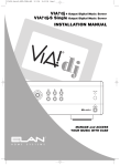
Included with the
C2RoHS
Communications
Controller, you will find two “Quick Reference”
Telephone Feature Cards.
01
02
03
04
05
06
07
08
09
10
(01-10)
P/N 9900870 RevA
Figure 1-2: Quick Reference Card
The C2’s phone features are easy to remember and use, but these guides will come in
handy for those who are unfamiliar with the system or as a refresher.
The C2 also gives you the capability of activating up to four low voltage relays from your
telephone keypad. These relays can be assigned to any home automation device of your
choosing. We have left you a labeling space beside each relay command on the bottom of the
Quick Reference Card.
Page 14
© ELAN Home Systems 2009 • All rights reserved.
ELAN
HOME
SYSTEMS
C2
INSTALLATION MANUAL
A Quick Explanation
All telephone feature commands are initiated from the keypad of your touch tone phone. They
are simple to use and easy to remember! All telephone feature commands begin with the #
(pound) symbol (factory preset).
NOTE: You have the option of choosing the * (star) symbol as the beginning
command key. This is selectable via DIP switch number 1 on the front of the
C2. You may wish to select the star (*) command key if the pound symbol
is not compatible with your telephone/home office equipment or security
system that you are currently using in the home.
The second key press in each command coincides with the first letter of that feature––for
instance to place a caller on Hold, press #, then 4 (the H key on your telephone keypad).
The C2 feature key press sequences can also be programmed to your telephone’s Speed
Dial buttons, For example: #,P can be programmed to Speed Dial Number 1 for Paging
throughout the home; #,D,1 and #,D,2 can be programmed to Speed Dial Numbers 2 & 3 for
instant doorspeaker communication; #1,1 (activate relay #1) can be programmed to Speed
Dial Number 4 to turn the lights on throughout the house at the press of a single digit (X-10
lighting control module or similar device required).
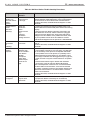
How To
Page- To Page throughout the house, simply press #, then 7 (the P key on your telephone
keypad). Speak into the phone receiver and your voice will be heard throughout the
house over the system’s speakers. If music is present on the system’s speakers, it will
automatically mute - allowing your page to be heard. If you have a caller on the line,
they will automatically be put on hold. You can get the caller back by simply pressing
the flash hook.
Group Page - If the Group Paging feature is enabled in the system configuration software
(S86A and S86P only), press #, then 7, then the number of the Page Group (1-9) you
wish to activate. Only the Zones assigned to that Group will switch to the Page audio.
Multiple Groups may be Paged by pressing #, then 7, and then the numbers of the
Groups you wish to Page. #7 + (1,3,5,6), for example. #7 + 9 = Whole House Page.
Zones may be assigned to multiple Groups.
Phone-To-Phone Intercom - This feature allows you to first, Page a family member over the
house speakers, then speak with them over the phone without the conversation being
heard over the in-wall speakers. To perform this function, simply press #, then 7 (the P
key on your keypad) followed by the numeric 0 key.
Place A Caller On Hold - To place a caller on hold, simply press #, then 4 (the H key on your
keypad) and hang up. The call can then be taken on another phone elsewhere in your
home. Music-On-Hold is available to the outside caller while on hold.
Communicate With a Door Station - To speak with visitors at any one of eight entrances to
your home, simply press #, then 3 (the D key on your telephone keypad) then the
number for the Door Station you wish to communicate with (1-8). (Requires ELAN Door
Station Assembly DSF3, DSS3, or DSC3). Should you need to communicate with
multiple Door Stations at the same time, you can toggle between them by pressing #, 3
(to speak with the door station that most recently had it’s DB pressed), then 2 (speak
with Door Station 2), then 3 (speak with Door Station 3), then 1 (speak with Door
Station1), then 7 (speak with Door Station 7) and so on.
© ELAN Home Systems 2009 • All rights reserved.
Page 15
C2
INSTALLATION MANUAL
ELAN
HOME
SYSTEMS
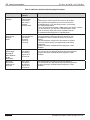
Activate A Door Latch - If you wish to activate a door latch, simply press #, then 3 (the D key
on your telephone keypad) followed by a 0 (the door station that most recently had it’s
DB pressed.), #, 3, 1, 0 (Door Station #1), #, 3, 2, 0 (Door Station #2), #, 3, 3, 0 (Door
Station #3) or #, 3, 4, 0 (Door Station #4). The door latch relay will remain open as long
as you hold the 0 key. Requires ELAN Door Station Assembly DSF3, DSS3, or DSC3 and
a latch mechanism installed at the door. Most cordless phones put out a fixed length
tone no matter how long you hold the button down.
Door Chime Select/Change - You may customize the chime that each door station makes. To
select or change this sound, press #, 2, 0 then the number of the desired Door Station,
then the desired chime (01-10). For example, to change Door Station 1 to chime #3,
press #, 2, 0, 1, 0, 3. To change Door Station 3 to chime 7, press #, 2, 0, 3, 0, 7.
Door Station Chime On/Off - You will hear the door chime through the Door Station speaker,
to provide audible feedback for the person at the Door Station. You may turn the chime
for each Door Station On or Off using the telephone. Press #, 5, 3, then the number of
the desired Door Station, then 0 (for OFF) or 1 (for ON). For example, to disable door
chime over Door Station 3, press #, 5, 3, 3, 0. To enable door chime over Door Station
1, press #, 5, 3, 1, 1.
Mute Music - When your phone rings, music through the system’s speakers will mute
automatically until the phone is answered, or the caller hangs up. If you want to mute
the audio after you answer the call, simply press #, then 6 (the M key on your telephone
keypad). The music will mute for the duration of the call.
Activate A Relay - Up to four relay-controlled devices can be connected to the C2. To
activate Relay 1, press #,1,1. To activate Relay 2, press #,1,2. To activate Relay 3, press
#,1,3. To activate Relay 4, press #,1,4. The relay is activated for the duration you press
the button.
Line Off-Hook Alert Enable/Disable - To turn the Line Off-Hook Alert On for Line 1, press #,
5, 6, 1, 1. To turn the Line Off-Hook Alert Off for Line 1, press #, 5, 6, 1, 0. To turn the
Line Off-Hook Alert On for Line 2, press #, 5, 6, 2, 1. To turn the Line Off-Hook Alert Off
for Line 2, press #, 5, 6, 2, 0.
Line On-Hold Alert Enable/Disable - To turn the Line On-Hold Alert On for Line 1, press #, 5,
4, 1, 1. To turn the Line On-Hold Alert Off for Line 1, press #, 5, 4, 1, 0. To turn the
Line On-Hold Alert On for Line 2, press #, 5, 4, 2, 1. To turn the Line On-Hold Alert Off
for Line 2, press #, 5, 4, 2, 0.
System Bypass (#9) - To bypass the C2 allowing to access voice mail features or enter
information into automated phone systems such as banks, credit card companies, utility
companies, etc. press #, 9.
FACTORY DEFAULT - To restore the C2 to Factory Default condition, press #, 0, 3, 3, 3.
Note: This will erase all previously customized settings!
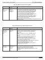
Fax Machines, Modems, and Caller ID Boxes
Generally, these types of telephone equipment work well with the C2 Communcation
Controller.
Paging
• Pick up any phone and press #, 7 (P) or #, 7 + (Group). Your page will be heard through all the speakers in the
house. If there was music playing when you initiated the page, the music will mute for the
duration of the page and come back on when you hang up the phone.
• Following a #,7 command with a numeric 0 will re-engage the audio over the speakers,
and connect your phone to the other phones on your line. The 0 can be initiated either
by the person performing the page or by a person picking up another extension.
Page 16
© ELAN Home Systems 2009 • All rights reserved.
ELAN
HOME
SYSTEMS
C2
INSTALLATION MANUAL
Incoming Calls While Paging
• While in page mode, if there is an incoming call you will hear a ring over the handset
every fourth ring. To access the caller, press the flash-hook button.
• While on a phone-to-phone intercom (#,7,0), if there is an incoming call, you will hear
the phone ring over the handset every fourth ring. To access the caller press any digit
except “0” or the flash-hook button.
Paging With A Caller On Line
• Pressing #, 7 (P) puts the caller on hold while you page. Pressing the flash-hook button
will bring the caller back on line. If you hang up the phone after paging, the person you
paged need just pick up any phone in the house and the caller will be there.
• If you followed a #,7 command with a numeric 0 to initiate a phone-to-phone intercom,
press any digit, or the flash-hook button to get the caller back.
Incoming Calls While Using the Door Station Assembly
• Press #,3 (D) to initiate two-way communications to your ELAN Door Stations.
• If, while communicating via a door station, there is an incoming call, you will hear an
alert over the handset every fourth ring. To access the caller, press the flash-hook
button. To re-access the door station you must press the #,3 (D) keys again.
© ELAN Home Systems 2009 • All rights reserved.
Page 17
C2
ELAN
INSTALLATION MANUAL
HOME
SYSTEMS
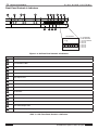
Front Panel Controls & Indicators
1
2
3
4
5
[ ]
[ ]
6
15
7
14
9
8
13
10
11
12
2
*
85
1.25
65
.75
DIP SWITCHES
1
#
3
4
5
6
7
8
1 - #/* POUND/STAR
2 - 65/85 DEBOUNCE
3 - .75/1.25 FLASHOOK
4 - future use
5 - future use
6 - future use
7 - future use
8 - future use
Figure 1-3: C2 Front Panel Controls & Indicators
Item
Description
1
Mute/Telemute Status LED
2
Line 1&2 Status LEDs
3
Page LED
4
Doorbell Status (1-4) LEDs
5
Relay Status (1-4) LEDs
6
Page Output Level
7
Line 1 Music-On-Hold Level
8
Door Station Microphone Input Level
9
Mini "B" USB Connector
10
DIP Switches
11
Power Indicator LED
12
Door Station Speaker Output Level
13
Line 2 Music-On-Hold Level
14
Door Chime Output Level
15
Front Access Door (Shown Open)
Table 1-1: C2 Front Panel Controls & Indicators
Page 18
© ELAN Home Systems 2009 • All rights reserved.
ELAN
HOME
C2
SYSTEMS
INSTALLATION MANUAL
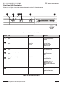
Front Panel LED Description
Figure 1-4 and Table 1-1 provide color and description of the C2 Communications
Controller front panel LEDs.
1
2
3
4
5
[ ]
[ ]
6
OPEN
ACCESS
DOOR
Figure 1-4: C2 Front Panel LEDs
Item#
LED
Indication
Status
1
Mute Status
(Red)
Solid ON
During music mute
function (#,6). Default
is OFF.
2
Line 1/Line 2 Status
(Red)
Flashing
Slow Wink
Solid ON
Incoming call
Call On-Hold
Phone Off-Hook.
Default is OFF
3
Page Active
(Red)
Solid ON
During page function
(#,7). Default is OFF
4
Door Bell Status (D1-D4)
(Red)
Solid ON
During door chime
duration. Default is
OFF
5
Relay Status (R1-R4)
(Red)
Solid ON
During relay activation,
remains active
until button is
released. (#,1,1 for
Relay 1, #,1,2 for
Relay 2 etc.) Default is
OFF.
6
Power Indicator
(Blue)
Solid ON
Indicates Power
Switch is set to the ON
position. Default is
ON.
Table 1-2: C2 Front Panel LED’s
© ELAN Home Systems 2009 • All rights reserved.
Page 19
C2
ELAN
INSTALLATION MANUAL
HOME
SYSTEMS
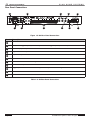
Rear Panel Connections
1
2
IN
SUM
4
3
PG
IN
TRIGGERS
OUT
5
PG/DB OUT
L
DB 1
POWER
OUT
VIA!NET
11
10
2
+ -
{
1
+ -
DB 2
OUTPUTS
+ -
INPUTS
+ -
+ -
+ -
VCO
+12V
GND
POWER
NC C NO
NC C NO
NC C NO
NC C NO
RELAY 1
RELAY 2
RELAY 3
RELAY 4
9
PHONE
LINE 1/2
TELCO
LINE 1/2
OUT
IN
+ - + R
AUDIO LOOP
MOH IN
(MONO)
DOOR STATION
BUS
8
7
6
Figure 1-5: C2 Rear Panel Connections
Item#
Description
1
Power Switch ON/OFF
2
Sum and PG Trigger Outputs (3.5mm Mono); DB1 and DB2 Trigger Outputs (3.5mm stereo)
3
Audio Loop Input/Output Jacks RCA Stereo
4
Page Door Chime Output RCA Mono
5
Output to Telephones RJ-14
6
Input from Telco RJ-14
7
Door Station Bus Removable Locking Connector
8
Music-On-Hold Input Jack RCA Mono
9
Trigger Inputs-Volume Control Override-Relay Power-Relays Removable Locking Connectors
10
VIA!NET IN/OUT RJ-45
11
AC Power Cord
Table 1-3: C2 Rear Panel Connections
Page 20
© ELAN Home Systems 2009 • All rights reserved.
ELAN
HOME
C2
SYSTEMS
INSTALLATION MANUAL
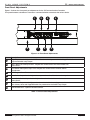
Front Panel Adjustments
Figure 1-5 shows the front panel pot adjustments for the C2 Communications Controller.
Turn potentiometers clockwise to increase or counterclockwise to decrease the various levels.
1
8
2
7
3
6
4
5
Figure 1-6: Front Panel Adjustments
Item
Description
1
Page Output Level - Adjusts the PAGE audio volume level presented to the Page/ Doorbell
Output and Audio Loop Output.
2
Line 1 Music On Hold Input Level - Adjusts the volume level of the music heard over
Phone Line 1.
3
Door Station Microphone Input Level -Adjusts the volume level of all door station
microphones.
4
USB Program Port - Future use.
5
Door Station Output Level - Adjusts the output volume for all the door station speakers.
6
Line 2 Music On Hold Input Level - Adjusts the volume level of the music heard over
Phone Line 2.
7
Door Chime Output Level - Adjusts the volume level of the internally generated sounds door chimes, alerts and Page/DB Audio Out presented to the Audio Loop Output.
8
Front Access Door - Opens to access controls.
Table 1-4: Front Panel Adjustments
© ELAN Home Systems 2009 • All rights reserved.
Page 21
C2
ELAN
INSTALLATION MANUAL
HOME
SYSTEMS
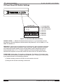
C2 Front Panel DIP Switch Settings
DIP SWITCHES
*
1.25
#
.75
3
85
2
65
1
4
5
6
7
8
1 - #/* POUND/STAR
2 - 65/85 DEBOUNCE
3 - .75/1.25 FLASHOOK
4 - future use
5 - future use
6 - future use
7 - future use
8 - future use
Figure 1-7: Front Panel DIP Switch Setting
POUND”#”/STAR “*” - Selects the telephone button press (# or *) you would like to use as
the initiator for all ELAN telephone communication/ relay features (i.e. #,P for PAGE, or *,P for
PAGE. The default is #.
DEBOUNCE - Selects either 65 milliseconds or 85 milliseconds. Used to eliminate intermittent
“drop-outs” during a phone conversation. These “drop-outs” (usually 3 seconds in duration)
are caused when certain speaking voices, usually female, produce frequencies similar to
those produced when a “#” or “*” button is pressed on a touch-tone phone. Should you
experience this symptom, move the dip switch from 65 ms to 85 ms. The default is 65 ms.
FLASH HOOK - Select either .75 seconds or 1.25 seconds. The default is .75 seconds. Used
in homes with CALL WAITING, increase FLASH HOOK time from .75 seconds to 1.25 seconds
if you experience either of the following symptoms:
1) Trouble accessing a second call while on the line with the first call.
2) Losing the first call after accessing a second call.
Page 22
© ELAN Home Systems 2009 • All rights reserved.
ELAN
HOME
C2
SYSTEMS
INSTALLATION MANUAL
Chapter 2: C2 System Design Overview
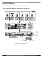
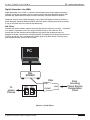
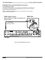
Stand-Alone Stereo System Application
The C2 can be used in stand-alone applications without the use of an ELAN Multi-Room
Controller. Figure 2-1 below shows the C2 being utilized with a stereo receiver and a
dedicated tuner for Music-On-Hold. The scenario will provide complete Paging, Door Station
Communications, Music-On-Hold, and relay functions.
PAGE AUDIO, DOOR CHIME AUDIO,
ON-HOLD ALERT, OFF-HOOK ALERT
TELEMUTE
ELAN DOOR DOORSTATIONS
DSS3/DSF3/DSC3
ELAN
VOLUME
CONTROLS
W/OVERRIDE
FEATURE
From Phone
Company
(2 Lines)
LOW VOLTAGE RELAYS
FOR LIGHTING, SPRINKLERS,
GARAGE DOOR, ETC
C2
IN
SUM
PG
IN
TRIGGERS
OUT
PG/DB OUT
L
1
+ -
2
+ -
+ -
+ -
+ -
+ -
+12V
GND
NC C NO
NC C NO
NC C NO
NC C NO
RELAY 1
RELAY 2
RELAY 3
RELAY 4
PHONE
LINE 1/2
TELCO
LINE 1/2
OUT
IN
+ - + R
POWER
DB 1
OUT
VIA!NET
DB 2
OUTPUTS
INPUTS
VCO
POWER
AUDIO LOOP
MOH IN
(MONO)
DOOR STATION
BUS
STEREO SYSTEM
(RECEIVER, PRE-AMP, POWER AMP)
Z•POWER
DEDICATED TUNER FOR MUSIC-ON-HOLD
To Telephone
Devices
Figure 2-1: Stand-Alone Stereo Design Overview
© ELAN Home Systems 2009 • All rights reserved.
Page 23
C2
ELAN
INSTALLATION MANUAL
HOME
SYSTEMS
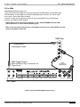
S66A Design Application
The C2 will provide all communication functions when used with an ELAN S66A
Integrated Multi-Zone Controller. Figure 2-2 below shows an ELAN S66A, and a C2 in a six
zone system.
NOTE: Volume Controls with Override are NOT required in this application.
1
2
3
4
5
ZONE 3
ZONE 4
ZONE 5
ZONES
6
KEYPADS
ZONE 1
ZONE 2
ZONE 6
S66A
C
US
C2 COMMUNICATION CONTROLLER
IN
SUM
PG
IN
OUT
TRIGGERS
PG/DB OUT
L
1
+ -
2
+ -
+ -
+ -
+ -
+ -
+12V
GND
NC C NO
NC C NO
NC C NO
NC C NO
RELAY 1
RELAY 2
RELAY 3
RELAY 4
PHONE
LINE 1/2
TELCO
LINE 1/2
OUT
IN
From Phone
Company
(2 Lines)
+ - + R
POWER
DB 1
OUT
VIA!NET
DB 2
OUTPUTS
INPUTS
VCO
POWER
AUDIO LOOP
MOH IN
(MONO)
DOOR STATION
BUS
To Telephone
Devices
LOW VOLTAGE RELAYS
FOR LIGHTING, SPRINKLERS,
GARAGE DOOR, ETC
ELAN
DOOR STATION #1
ELAN
DOOR STATION #2
Figure 2-2: S66A Design Overview
Page 24
© ELAN Home Systems 2009 • All rights reserved.
ELAN
HOME
C2
SYSTEMS
INSTALLATION MANUAL
S86A/P Design Application
The C2 interfaces easily with the S86P Multi-Room A/V Controller. Figure 2-3 shows
a S86P and a C2 in a six zone system.
ZONES
1
2
3
ZONE 1
ZONE 2
4
ZONE 3
5
ZONE 4
6
ZONE 5
ZONE 6
S86P
2
1
3
SOURCE IR OUTPUTS
4
5
7
6
ALL IR
OUT
8
1
ELAN SENSE INPUTS
2
3
4
5
IN
6
SOURCE INPUT 1
V
120VAC 60Hz.
400W
ZONE 1
ZONE 2
ZONE 3
IN
SYSTEM
TRIGGER
OUT
PROGRAMMABLE TRIGGER OUTPUTS
IN
1
2
3
4
5
6
ZONE PRE-AMP OUTPUTS
SOURCE IR
EXPANSION PORTS
V
V
V
ZONE 6
V
SOURCE INPUT 5
LOOP OUTPUT 1
L
R
V
L
SOURCE INPUT 3
R
V
SOURCE INPUT 6
LOOP OUTPUT 2
L
R
V
L
SOURCE INPUT 4
R
V
SOURCE INPUT 7
LOOP OUTPUT 3
L
R
V
L
R
PG IN
V
V
PG OUT
ZONE 5
SOURCE INPUT 2
R
VIA!NET IN
ELAN RS-232
PORTS
ZONE 4
L
PAGE
TRIGGER
OUT
VIA!NET OUT
L
OUT
OUT
L
L
L
V
SOURCE INPUT 8
LOOP OUTPUT 4
L
R
L
MOH OUT
R
1
R
2
R
3
R
4
R
5
LOOP OUTPUT 5
6
LOOP OUTPUT 6
LOOP OUTPUT 7
LOOP OUTPUT 8
C2 COMMUNICATION CONTROLLER
IN
SUM
PG
IN
OUT
TRIGGERS
PG/DB OUT
L
1
+ -
2
+ -
+ -
+ -
+ -
+ -
+12V
GND
NC C NO
NC C NO
NC C NO
PHONE
LINE 1/2
TELCO
LINE 1/2
OUT
IN
From Phone
Company
(2 Lines)
+ - + -
NC C NO
R
POWER
DB 1
OUT
VIA!NET
DB 2
OUTPUTS
INPUTS
VCO
POWER
RELAY 1
RELAY 2
RELAY 3
RELAY 4
AUDIO LOOP
MOH IN
(MONO)
DOOR STATION
BUS
To Telephone
Devices
LOW VOLTAGE RELAYS
FOR LIGHTING, SPRINKLERS,
GARAGE DOOR, ETC
ELAN
DOOR STATION #1
ELAN
DOOR STATION #2
Figure 2-3: S86P Design Overview
© ELAN Home Systems 2009 • All rights reserved.
Page 25
C2
ELAN
INSTALLATION MANUAL
HOME
SYSTEMS
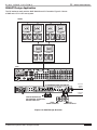
S128P Design Application
The C2 interfaces easily with the S128P Multi-Room A/V Controller. Figure 2-4 shows
a S128P using variable outputs, along with a D16 Digital Power Amplifier to control eight
zones. In this scenario, volume controls are not needed since variable outputs are being used
from the S128P.
ZONES
2
1
3
4
KEYPADS
ZONE 1
ZONE 2
5
ZONE 3
6
ZONE 5
ZONE 6
ZONE 4
7
8
ZONE 7
ZONE 8
D16
1
POWER
I
O
2
+
_
3
4
5
6
7
IN
8
+
+
+
+
_
_
_
_
OUT
1
BUS
A
2
+
+
+
_
Txx AL FUSE
REPLACE WITH SAME
TYPE AND RATING
ONLY.
_
_
9
+
+
11
10
14
16
15
12
14
16
ALL
ON
IN
OUT
OUTPUT
USB
Digital Power Amplifier
VIA!NET
ETHERNET
OUT
IN
OUT
8
OUT
IN
13
IR
Model D16
IN
7
6
OUT
IR
_
15
OUT
11
INPUT
_
13
12
+
IN
5
IN
OUT
9
BUS
B
10
SPEAKER OUTPUTS (CLASS 2 WIRING) 60W/CH @ 8 ohms
OUT
4
IN
120 VAC 60 Hz
1440W
IN
3
1/2
9/10
+12VDC
TRIGGER
OUT
3/4
5/6
7/8
11/12
13/14
15/16
+12V TRIGGER INPUTS
S128P
C2 COMMUNICATION CONTROLLER
IN
SUM
PG
IN
OUT
TRIGGERS
PG/DB OUT
L
1
+ -
2
+ -
+ -
+ -
+ -
+ -
+12V
GND
NC C NO
NC C NO
NC C NO
NC C NO
RELAY 1
RELAY 2
RELAY 3
RELAY 4
PHONE
LINE 1/2
TELCO
LINE 1/2
OUT
IN
From Phone
Company
(2 Lines)
+ - + R
POWER
DB 1
OUT
VIA!NET
DB 2
OUTPUTS
INPUTS
VCO
POWER
AUDIO LOOP
MOH IN
(MONO)
DOOR STATION
BUS
To Telephone
Devices
LOW VOLTAGE RELAYS
FOR LIGHTING, SPRINKLERS,
GARAGE DOOR, ETC
ELAN
DOOR STATION #1
ELAN
DOOR STATION #2
Figure 2-4: S128P Design Overview
Page 26
© ELAN Home Systems 2009 • All rights reserved.
ELAN
HOME
C2
SYSTEMS
INSTALLATION MANUAL
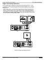
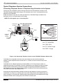
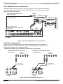
Trigger Input Design Application
The C2’s Trigger Inputs are designed to accept a dry contact closure across the “+ “ and
“-” terminals. An added benefit is that the Trigger Inputs provide 12VDC on the “+” terminal
and ground on the “-” terminal (see Figure 2-5). This provides the ability to illuminate lighted
doorbell buttons.
NOTE: Trigger inputs 1 and 2 will always trigger the Door Chime assigned to Door
Station 1 and Door Station 2 alerts respectively. In order to differentiate between
Door Stations 1 and 2 alerts and Triggers 1 and 2, set the I.D. DIP Switches on the
door stations DS 1 and DS 2 to DS 3 and DS 4. This will allow different alerts for the
two door stations and the two trigger inputs
DRIVEWAY SENSORS
NO
MOTION SENSORS
C
NO
C
C2
IN
SUM
PG
TRIGGERS
1
+ -
DB 1
POWER
OUT
VIA!NET
DB 2
OUTPUTS
2
+ -
INPUTS
LIGHTED DOORBELL
C2
IN
SUM
PG
TRIGGERS
1
+ -
POWER
DB 1
OUT
VIA!NET
DB 2
OUTPUTS
2
+ -
INPUTS
Figure 2-5: Trigger Input Design Overview
© ELAN Home Systems 2009 • All rights reserved.
Page 27
C2
ELAN
INSTALLATION MANUAL
HOME
SYSTEMS
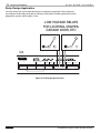
Relay Design Application
The C2 provides four active relays that respond to telephone commands. These relays can
be configured as Normally Open (NO) or Normally Closed (NC). Possible applications include
garage door openers, blinds, gates, or lifts.
LOW VOLTAGE RELAYS
FOR LIGHTING, DRAPES,
GARAGE DOOR, ETC
C2
TRIGGERS
1
+ -
2
+ -
INPUTS
+ -
+ -
+ -
VCO
+ -
+12V
GND
POWER
NC C NO
NC C NO
NC C NO
NC C NO
RELAY 1
RELAY 2
RELAY 3
RELAY 4
Figure 2-6: Relay Design Overview
Page 28
© ELAN Home Systems 2009 • All rights reserved.
ELAN
HOME
C2
SYSTEMS
INSTALLATION MANUAL
Chapter 3: C2 System Connections Overview
This chapter shows C2 Communications Controller system connections.
System Control
Cat-5 cable should be used for all C2 system connections including incoming phone lines,
input and output triggers, ELAN Door Stations (including camera connections), volume
controls with override and relays.
CAUTION: ALWAYS remove power to the C2 along with any other
electronics equipment prior to making any connections to or from the
C2. Set the Power Switch on the back of the C2 to the OFF
position prior to making connections.
C2 Rear Panel Connections
The following section describes connections to the C2 Communications Controller.
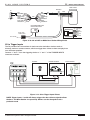
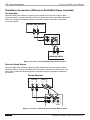
C2 to VMOS or VSOS Volume Controls
When connecting rotary Volume Controls with Override to the C2, simply connect “+” from
the C2’s VCO connector to “VC+” of the Volume Control. Connect “-” from the C2’s
VCO connector to “VC-” of the Volume Control. Cat-5 is typically used for this purpose.
CAUTION: ALWAYS remove power to the C2 along with any other
electronics equipment prior to making any connections to or from the
C2. Set the Power Switch on the back of the C2 to the OFF
position prior to making connections.
VMOS or VSOS
Volume Control
VCO
+ - + - + - + -
C2
Blue
White/Blue
Orange
White/Orange
Green
White/Green
Brown
White/Brown
Override
N/C
N/C
N/C
N/C
N/C
Ground
N/C
Cat-5
VC+
Blue
White/Blue
Orange
White/Orange
Green
White/Green
Brown
VC White/Brown
VC+
VC -
Figure 3-1: C2 to VMOS or VSOS Volume Controls Wiring Pinout
C2 to Electronic Volume Control
When connecting the C2 directly to Electronic Volume Controls, splice Cat-5 onto an RJ-45 to
pigtail connector. Connect the Blue Override (pin 1) wire to “+” of the C2’s VCO connector.
Connect the Brown Ground wire (pin 7) to the “-” of the C2’s VCO connector. Plug the RJ-45
directly into the RJ-45 connector on the back of the Electronic Volume Control.
© ELAN Home Systems 2009 • All rights reserved.
Page 29
C2
ELAN
INSTALLATION MANUAL
HOME
SYSTEMS
CAUTION: ALWAYS remove power to the C2 along with any other
electronics equipment prior to making any connections to or from the
C2. Set the Power Switch on the back of the C2 to the OFF
position prior to making connections.
Blue
White/Blue
Orange
White/Orange
Green
White/Green
Brown
White/Brown
Override
IR OUT
IR IN
N/C
N/C
+12V
GND
N/C
RJ-45 to
Pigtail
VSE2
To +12V
From IR Source
(IR Sensor,
Source Output, etc.)
To IR Device
(IR Emitter,
Zone Input, etc.)
GND
VCO
+ - + - + - + -
2
Standard ELAN RJ-45 Pin-Out
FRONT
PIN # COLOR CODE
1
2
3
4
5
6
7
8
TAB
BLUE
WHITE/BLUE
ORANGE
WHITE/ORANGE
GREEN
WHITE/GREEN
BROWN
WHITE/BROWN
CABLE
Figure 3-2: C2 to VSE2 Wiring Pinout
C2 to PVSE Electronic Volume Control Precision Panel
When connecting the C2 to a PVSE Precision Panel, use an RJ-45 to pigtail connector.
Connect the Blue Override (pin 1) wire to “+” of the C2’s VCO connector.
Connect the White/Blue Ground wire (pin 2) to the “-” of the C2’s VCO connector. Plug the
RJ-45 into the OVERRIDE IN connector on the PVSE. See the PVSE Installation manual for
additional wiring for the PVSE and Electronic Volume Controls.
CAUTION: ALWAYS remove power to the C2 along with any other
electronics equipment prior to making any connections to or from the
C2. Set the Power Switch on the back of the C2 to the OFF
position prior to making connections.
PVSE
Override IN
Standard ELAN RJ-45 Pin-Out
Blue
Wh/Blue
Orange
Wh/Orange
Green
Wh/Green
Brown
Wh/Brown
Override
Ground
N/C
N/C
N/C
N/C
N/C
N/C
PIN # COLOR CODE
OVERRIDE
IN
1
2
3
4
5
6
7
8
OVERRIDE
OUT
FRONT
VCO
+ - + - + - + -
C2
TAB
Cat-5
BLUE
WHITE/BLUE
ORANGE
WHITE/ORANGE
GREEN
WHITE/GREEN
BROWN
WHITE/BROWN
CABLE
Figure 3-3: C2 to PVSE Electronic Volume Control Precision Panel Wiring Pinout
Page 30
© ELAN Home Systems 2009 • All rights reserved.
ELAN
HOME
C2
SYSTEMS
INSTALLATION MANUAL
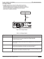
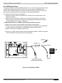
C2 Trigger Outputs
The Trigger Output choices are SUM, PG, DB1 and DB2. See Table 3-1.
CAUTION: ALWAYS remove power to the C2 along with any other
electronics equipment prior to making any connections to or from the
C2. Set the Power Switch on the back of the C2 to the OFF
position prior to making connections.
ELAN MULTI-ROOM CONTROLLER
Page Trigger In
3.5mm
mono-mini
cable
C2
IN
SUM
PG
TRIGGERS
1
+ -
DB 1
POWER
OUT
VIA!NET
DB 2
OUTPUTS
2
+ -
INPUTS
Figure 3-4: C2 Trigger Outputs
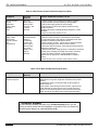
Table 3-1: C2 Trigger Outputs
Trigger Output
Description
SUM
Activates when page and doorbell occurs. Use SUM if you want music to mute and the page/
doorbell audio to be heard over the house speakers. SUM is used to trigger
the page/doorbell input of an ELAN controller, such as a S66A, S128P. Use
a 3.5 mono interconnect cable.
PG
Activates only when a page occurs. Use PG if you want trigger automated events when a
page is initiated, see Figure 3-22 and Figure 3-26 for applications. Use a 3.5mm stereo interconnect cable.
DB1
Activates when doorbell from Door Station 1 is pressed. Use DB1 if you want trigger automated events when the doorbell from Door Station 1 is pressed, see Figure 3-22
and Figure 3-26 for applications. Use a 3.5mm stereo interconnect cable.
DB2
Activates when doorbell from Door Station 2 is pressed.Use DB2 if you want trigger automated events when the doorbell from Door Station 2 is pressed, see Figure 3-22 and Figure 3-26
for applications. Use a 3.5mm stereo interconnect cable.
© ELAN Home Systems 2009 • All rights reserved.
Page 31
C2
ELAN
INSTALLATION MANUAL
HOME
SYSTEMS
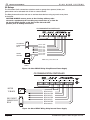
C2 Relays
The C2 utilizes Cat-5 connections to devices such as garage door openers, blinds, and
gates which can be activated with 12 Volt or contact closure.
The Relay feature allows the end user to activate these devices using any touch-tone phone
in the home.
CAUTION: ALWAYS remove power to the C2 along with any other
electronics equipment prior to making any connections to or from the
C2. Set the Power Switch on the back of the C2 to the OFF
position prior to making connections.
C2 COMMUNICATION CONTROLLER
IN
TRIGGERS
L
+ -
+
-
+ -
+ -
+12V
GND
NC C NO NC C NO NC C NO NC C NO
R
VCO
DRY CONTACT
GARAGE DOOR
RELAY
POWER
RELAY 1
RELAY 2
RELAY 3
RELAY 4
RELAY #1 COM
RELAY #1 N.O.
RELAY #2 COM
RELAY #2 N.O.
RELAY #3 COM
RELAY #3 N.O.
RELAY #4 COM
RELAY #4 N.O.
MOTOR
TO BLINDS
NOTE: Relay current limit is 4A
12VDC POWER
SUPPLY
Figure 3-5: C2 to RELAY Wiring Using External Power Supply
C2 COMMUNICATION CONTROLLER
IN
TRIGGERS
L
+ -
+
-
+ -
+ -
+12V
GND
NC C NO NC C NO NC C NO NC C NO
R
VCO
MOTOR
TO BLINDS
DRY CONTACT
GARAGE DOOR
RELAY
POWER
RELAY 1
RELAY 2
RELAY 3
RELAY 4
RELAY #1 N.O.
RELAY #2 COM
RELAY #2 N.O.
RELAY #3 COM
RELAY #3 N.O.
RELAY #4 COM
RELAY #4 N.O.
Figure 3-6: C2 to RELAY Wiring Using Internal Power Supply
Page 32
© ELAN Home Systems 2009 • All rights reserved.
ELAN
HOME
C2
SYSTEMS
INSTALLATION MANUAL
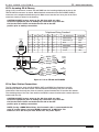
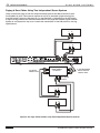
C2 To Incoming CO & Phones
Using an RJ-14 connector, connect TIP and RING from the incoming telephone service to the
TELCO LINE1/2 connector as shown. Make identical connections from the PHONES LINE1/2
connector to the telephone distribution point. Make sure to use the four inner pins of the RJ14
connector exactly as shown in the drawing.
CAUTION: ALWAYS remove power to the C2 along with any other
electronics equipment prior to making any connections to or from the
C2. Set the Power Switch on the back of the C2 to the OFF
position prior to making connections.
Telephone Wiring Standard
Pin
RJ25
1
2
X
X
X
3
X
X
T T RT RR
4
5
X
X
X
X
1 23456
6
X
Line 2
Line 1
RJ14
TIP
PHONE
LINE 1/2
TELCO
LINE 1/2
RING
Cat-5
TIP
RING
OUT
RJ11
Pair
T/R
+
TIA-568A (New)
USCO (Old)
3
2
T
T
+
+
White/Green
White/Orange
Orange
Black
X
1
R
-
Blue
Red
X
1
2
T
R
+
-
White/Blue
Orange
Green
Yellow
3
R
-
Green
Blue
Wh/Blu
Blue
Wh/Org
Orange
Line 1
Wh/Blu
Blue
Wh/Org
Orange
Line 1
From
Telco
Line 1
Line 2
Line 2
Cat-5
IN
RJ14
Connectors
Cat-5
TIP
RING
TIP
RING
Line 1
To
Phones
Line 2
Line 2
Cat-5
Figure 3-7: C2 to TELCO and PHONES
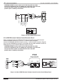
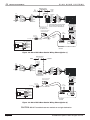
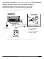
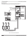
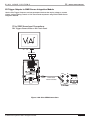
C2 to Door Station Connections
The C2 is designed to work with ELAN DSC3, DSF3, and DSS3 Door Stations to provide
doorbell push button and door station communications functionality. Use Cat-5 for these
connections. Note that only two wires are used to connect between the C2 and the door station.
The remaining wires of the Cat-5 are used for the DSC3’s camera functions (the camera does not
interact with the C2).
CAUTION: ALWAYS remove power to the C2 along with any other
electronics equipment prior to making any connections to or from the
C2. Set the Power Switch on the back of the C2 to the OFF
position prior to making connections.
NOTE: If using a VBRM Video Balun, Cat-5 network cable is recommended to be
used. IF a video balun is not used ELAN recommends 18 AWG wire. For
DSC3 runs over 500 feet you must double wire the power inputs.
© ELAN Home Systems 2009 • All rights reserved.
Page 33
C2
ELAN
INSTALLATION MANUAL
HOME
SYSTEMS
VBRM Video Balun
To
Video
Switcher
Video
Snap Lock
Connector
C2
+
+
-
Door Station
Bus
Blue
White/Blue
Orange
White/Orange
Green
White/Green
Brown
White/Brown
Blue
White/Blue
Orange
White/Orange
Green
White/Green
Brown
White/Brown
Cat-5
External
12VDC
Power
Power
*White/Brown
*Brown
*White/Green
*Green
White/Orange
Orange
White/Blue
Blue
DS DS+
Cat-5
* Splice White/Green with White /Brown
VID + and Green with Brown VID - for
camera runs between 500 &1000 feet.
Butt Splice
ELECTRONIC DOOR LATCH
RELEASE MECHANISM
-
LOW VOLTAGE
OUTPUT
Standard ELAN RJ-45 Pin-Out
FRONT
+DB- -DS+ 1RL2
TAB
BALUN
PIN # COLOR CODE
1
2
3
4
5
6
7
8
Purple
Blue
Gray
Yellow
22/24AWG
4-twisted pair
shielded
wire
Orange
Brown
To 110V AC
White
Green
+
Black
Red
To EXT.
DOORBELL
DOOR LATCH
POWER SUPPLY
*White/Brown
*Brown
*White/Green
*Green
White/Orange
Orange
White/Blue
Blue
Use for run from
0 to 1000 feet max.
PWR
GRD
PWR
GRD
VIDVID+
DS DS+
BLUE
WHITE/BLUE
ORANGE
WHITE/ORANGE
GREEN
WHITE/GREEN
BROWN
WHITE/BROWN
VID PWR
DSC3 DOOR
STATION
CABLE
Figure 3-8: C2 to DSC3 Door Station Wiring Pinout (Option 1)
VBRM Video Balun
To Video
Switcher
Video
C2
+
+
-
Door Station
Bus
Blue
White/Blue
Orange
White/Orange
Green
White/Green
Brown
White/Brown
Cat-5
Blue
White/Blue
Orange
White/Orange
Green
White/Green
Brown
White/Brown
External 12VDC
Power
Power
Snap lock
connector
DS DS+
White/Brown
Brown
White/Green
Green
White/Orange
Orange
White/Blue
Blue
RJ-45
Cat-5
*White/Brown
*Brown
*White/Green
*Green
White/Orange
Orange
White/Blue
Blue
Use for run from
0 to 500 feet max.
PWR
GRD
PWR
GRD
VIDVID+
DS DS+
ELECTRONIC DOOR LATCH
RELEASE MECHANISM
Butt Splice
-
+
Orange
Brown
White
Green
Standard ELAN RJ-45 Pin-Out
Purple
Blue
Gray
Yellow
To EXT.
DOORBELL
To 110V AC
Black
Red
DOOR LATCH
POWER SUPPLY
TAB
BLUE
WHITE/BLUE
ORANGE
WHITE/ORANGE
GREEN
WHITE/GREEN
BROWN
WHITE/BROWN
+DB- -DS+ 1RL2
1
2
3
4
5
6
7
8
BALUN
FRONT
PIN # COLOR CODE
VID PWR
CABLE
DSC3 DOOR
STATION
Figure 3-9: C2 to DSC3 Door Station Wiring Pinout (Option 2)
Page 34
CAUTION: DO NOT combine these two methods on a single destination.
© ELAN Home Systems 2009 • All rights reserved.
ELAN
HOME
C2
SYSTEMS
DSF3 or DSS3
DOOR STATION
Butt Splice
C2
+
+
-
Door Station
Bus
DS+
Blue
White/Blue DS Orange
White/Orange
Green
White/Green
Brown
White/Brown
Cat-5
Black
Red
White
Green
ELECTRONIC DOOR LATCH
RELEASE MECHANISM
-DS+ 1RL2
Blue
White/Blue
Orange
White/Orange
Green
White/Green
Brown
White/Brown
INSTALLATION MANUAL
Standard ELAN RJ-45 Pin-Out
DOOR LATCH
POWER SUPPLY
-
FRONT
PIN # COLOR CODE
+
1
2
3
4
5
6
7
8
TAB
To 110V AC
BLUE
WHITE/BLUE
ORANGE
WHITE/ORANGE
GREEN
WHITE/GREEN
BROWN
WHITE/BROWN
CABLE
Figure 3-10: C2 to DSF3 or DSS3 Door Station Wiring Pinout
C2 to Trigger Inputs
The C2 provides Cat-5 connections for basic two-wire doorbells or devices such as
driveway, motion or contact sensors, which can trigger door chimes or alerts and play them
over the house speakers.
Connect “+” and “-” from the triggering device to “+” and “-” of the TRIGGER INPUTS
connector as shown.
DOORBELL
C2
1
DRIVEWAY SENSORS
MOTION SENSORS
2
Figure 3-11: C2 to Trigger Inputs Pinout
NOTE: Trigger inputs 1 and 2 will always trigger the door chime assigned to Door
Station 1 and Door Station 2 respectively. Chimes can be changed to suit a
particular need.
© ELAN Home Systems 2009 • All rights reserved.
Page 35
C2
ELAN
INSTALLATION MANUAL
HOME
SYSTEMS
Typical Telephone Service Connections
Connecting Telephone Service & Telephone Surge Protection to the System
Connect the TIP and RING for each incoming phone line from the telephone company to the
TH31SRG Telephone Master Hub using a 110 punchdown tool. Up to 4 incoming lines can be
attached to the TH31SRG.
ELAN recommends using Cat-5 to make punchdowns to TH31SRG Telephone Master Hub.
See Figure 3-12 for wire punchdown color coding
NOTE: The C2 supports up to 2 incoming lines.
TH31 SRG TELEPHONE
MASTER HUB
Cat-5 Jumper
(included)
Wire Color Codes
Te le p ho ne M a ste r Hub ( Surg e , R J -31X, D isc o nne c t)
M o d e l TH 3 1 SR G
Orange
Wh/Org
From
Telco
In
Disconnect
Out
Orange
Telephone
Output
Surge
Warning
Cat-5
4 Pair UTP
4
R
T
R
4
T
3
R
T
R
3
T
2
R
T
1
R
T
Blue
Wh/Blu
Line 1
Blue
Wh/Blu
Cat-5
Line 2
TTRTRR
1 23456
RING
RING
Pair 2 Orange
R
1
T
Wh/Orange
2 lines from
telepone
company
RING
TIP
Green
Pair 3
TIP
Wh/Green
Wh/Org
R
2
T
RJ31X
Brown
Pair 4
Wh/Brown
Pair 1
2 lines to
TELCO on COM2
Cat-5
TIP
RING
Blue
TIP
Wh/Blue
ELAN recommends that telephone RJ-45
jacks be wired to the T568A standard.
RJ11
Line 1 TIP - White/Blue
Line 1 RING - Blue
Line 2 TIP - White/Orange
Line 2 RING - Orange
RJ14 Connection
Figure 3-12: Connecting Telephone Service to the TH31SRG Telephone Master Hub
The ELAN C2 is compatible with most touch-tone telephones and multi-line telephone
systems. Certain telephones that use the both # or * buttons for other functions may not be
compatible.
The ELAN C2 has a Ringer Equivalency Number (REN) of 0.7A. The maximum number of
telephones that may be connected in a home is dependent on the Ringer Equivalency Voltage
being provided to the home by the phone company and the Ringer Equivalency Number of
each telephone in the home. When added together, the REN of all the house phones plus the
C2 should not exceed 5 per telephone line.
Exceeding the Ringer Equivalency Voltage provided by the telephone company may result in
intermittent or no ring-in or a call from your local carrier. Ring boosters are available from your
phone company for a nominal fee. ELAN strongly recommends the use of telephone line surge
protection between the incoming phone line and the C2 Phone Input.
Page 36
© ELAN Home Systems 2009 • All rights reserved.
ELAN
HOME
C2
SYSTEMS
INSTALLATION MANUAL
Connecting Telephone Extensions to the TH48 Telephone Expansion Hub
The TH48 Telephone Expansion Hub lets the installer connect the C2 to up to eight dualline
telephone wall plate connections or sixteen single line telephones wall plate connection*.
NOTE: * In the single line configuration 8 wall plate connections would have Line 1
and 8 would be configured to Line 2, if applicable.
TH48 TELEPHONE
EXPANSION HUB
Wire Color Codes
Te le phone E xpa ns ion H ub (4 line s x 8 phone s )
Cat-5
4 Pair UTP
8
Exp a nsio n
Po rts
Orange
Te le p ho ne s
Wh/Org
R
4
T
In
R
3
T
RR 2
2
TT
O ut
Line 2
TTRTRR
1 23456
RING
Green
Pair 3
TIP
Wh/Green
Wh/Orange
Blue
Wh/Blu
To TH48
Expanision
Hub
(if more phones needed)
RING
TIP
RING
Pair 2 Orange
RR 1
1
TT
2 lines to
8 telepone
Line 1
wall plates
Brown
Pair 4
Wh/Brown
Pair 1
Blue
TIP
RING
TIP
Wh/Blue
2 lines to
TELCO on COM2 ELAN recommends that telephone RJ-45
jacks be wired to the T568A standard.
Cat-5
RJ11
Line 1 TIP - White/Blue
Line 1 RING - Blue
Line 2 TIP - White/Orange
Line 2 RING - Orange
RJ14 Connection
Figure 3-13: Connecting Telephone Service to the TH31 SRG Telephone Master Hub
© ELAN Home Systems 2009 • All rights reserved.
Page 37
C2
ELAN
INSTALLATION MANUAL
HOME
SYSTEMS
New Construction
ELAN recommends a “home-run” wiring network using Cat-5 twisted-pair telephone wire
from each telephone wall jack location to an ELAN TH48 Telephone Expansion Hub.
Telephone Master Hub w/Surge Protection
Model TH31SRG
(Surge, RJ31X, Disconnect )
From Phone
Company
To
Security
Ports
Disconnect
In
Out
From
TELCO
4
3
R
T
R
T
Surge
Warning
4
3
R
T
R
1
T
2
2
RJ31X
1
Telephone
Output
R
4
T
R
3
T
R
2
T
R
1
T
Surge
Protector
C2
Telephone Master Hub (4 Lines x 8 Phones)
Model TH48
PG/DB OUT
PHONE
LINE 1/2
TELCO
LINE 1/2
Espansion
Ports
+ - + -
MOH IN
(MONO)
DOOR STATION
BUS
OUT
R
4
T
R
3
T
Out
R
2
T
R
1
T
IN
Telephone Master Hub (4 Lines x 8 Phones)
Model TH48
Z•POWER
TH48 TELEPHONE
EXPANSION HUB
Telephones
In
Espansion
Ports
TH31SRG
4-Line TELEPHONE
HUB with
Surge Protection
Telephones
In
R
4
T
R
3
T
Out
R
2
T
R
1
T
SATELLITETV
MODEM LINE
FAX LINE
TH48 TELEPHONE
EXPANSION HUB
DUAL
TELEPHONE
WALLPLATES
4-TWISTED PAIR TELEPHONE WIRE (CAT-5)
Figure 3-14: New Construction Application
Page 38
© ELAN Home Systems 2009 • All rights reserved.
ELAN
HOME
C2
SYSTEMS
INSTALLATION MANUAL
Retrofit
Pre-existing “daisy-chained” wiring networks are perfectly compatible with the ELAN C2
Communication Controller.
C2
PG/DB OUT
PHONE
LINE 1/2
TELCO
LINE 1/2
+ - + -
From Phone
Company
Telephone Master Hub w/Surge Protection
Model TH31SRG
(Surge, RJ31X, Disconnect)
Ports
From
TELCO
4
3
Disconnect
In
Out
R
T
R
T
4
3
R
T
R
1
T
2
2
MOH IN
(MONO)
DOOR STATION
BUS
OUT
IN
To Security
Surge
Warning
RJ31X
1
Telephone
Output
R
4
T
R
3
T
R
2
T
R
1
T
TH31SRG
4-Line TELEPHONE
HUB with
Surge Protection
Surge
Protector
Telephone Expansion Hub (4 Lines x 8 Phones)
Model TH48
Espansion
Ports
Telephones
In
R
4
T
R
3
T
Out
R
2
T
R
1
T
Z•POWER
Telephone Expansion Hub (4 Lines x 8 Phones)
Model TH48
Espansion
Ports
Telephones
In
R
4
T
R
3
T
Out
R
2
T
R
1
T
TH48 TELEPHONE
EXPANSION HUB
SATELLITE TV
MODEM LINE
FAX LINE
TH48 TELEPHONE
EXPANSION HUB
Figure 3-15: Retrofit Application
© ELAN Home Systems 2009 • All rights reserved.
Page 39
C2
ELAN
INSTALLATION MANUAL
HOME
SYSTEMS
Connecting The C2 To A Multi-Line Telephone system
The C2 communication features (paging, door speaker communications, relay activation,
etc.) can be accessed from both Line 1 and Line 2. The TELEMUTE feature is available on both
C2 lines.
NOTE: Phone-to-phone intercom (#7,0) will only work with phones on the same
line. For example, you can not pick up Line 1 and intercom to someone on
Line 2.
TH31 SRG TELEPHONE
MASTER HUB
Cat-5 Jumper
(included)
Te le p ho ne M a ste r Hub ( Surg e , R J -31X, D isc o nne c t)
M o d e l TH 3 1 SR G
Orange
Wh/Org
2 lines from
telepone
company
Blue
From
Telco
In
Orange
Telephone
Output
Surge
Warning
Disconnect
Out
4
R
T
R
4
T
3
R
T
R
3
T
2
R
T
R
2
T
1
R
T
Wh/Org
R
1
T
RJ31X
Wh/Blu
Line 1
Blue
Wh/Blu
Cat-5
Line 2
2 lines to
TELCO on COM2
Cat-5
RJ11
TTRTRR
1 23456
RJ14 Connection
Wire Color Codes
Cat-5
4 Pair UTP
Brown
Pair 4
Wh/Brown
RING
TIP
RING
Green
Pair 3
TIP
Wh/Green
RING
Pair 2 Orange
Wh/Orange
Pair 1
Line 1 TIP - White/Blue
Line 1 RING - Blue
Line 2 TIP - White/Orange
Line 2 RING - Orange
TIP
RING
Blue
TIP
Wh/Blue
ELAN recommends that telephone RJ-45
jacks be wired to the T568A standard.
Figure 3-16: Connecting Telephone Service to the TH31 SRG Telephone Master Hub
Page 40
© ELAN Home Systems 2009 • All rights reserved.
ELAN
HOME
C2
SYSTEMS
INSTALLATION MANUAL
Digital Subscriber Line (DSL)
Digital Subscriber Line, or DSL, is a batch of technologies that provide a digital connection
(typically an Internet connection) over the copper wires of the local telephone network. DSL
provides high speed Internet access to home consumers in Europe and North America.
Telephone services were initially designed to carry “Plain Old Telephone Service” (POTS) or
Public Switched Telephone Network (PSTN) calls. DSL allows ordinary phone lines to provide
a way to carry data and voice services simultaneously.
DSL Filters
Installers will need to install a passive electronic filter (known variously as a “filter”, “microfilter”
or a “splitter”) up stream of the C2 if using the POTS service on the same line. This
ensures that the DSL modem and the telephone only receive the frequencies they are
designed to handle. The end user will need a splitter. The splitter is first thing connected to an
incoming phone line. Then, one side of the splitter goes to the DSL modem. The other side
goes through the filter to the C2 TELCO input.
PC
DSL
MODEM
Filter
DSL
To
House
Phones
PHONE
LINE 1/2
TELCO
LINE 1/2
OUT
IN
LINE
PHONE
From
Incoming
Phone Service
Demarcation
Point
Figure 3-17: DSL Filters
© ELAN Home Systems 2009 • All rights reserved.
Page 41
C2
ELAN
INSTALLATION MANUAL
HOME
SYSTEMS
Standalone Connections (Without an ELAN Multi-Room Controller)
Pre-Amp/Amp
Use stereo RCA patch cables to connect the C2’s AUDIO LOOP IN to the Pre-Amp’s Main
Outputs as shown. Connect the AUDIO LOOP OUT jacks to the Power Amp’s Main Inputs. This
allows the C2’s Page and Doorbell signals to be heard through the speakers connected to
the power amplifier.
PRE-AMP MAIN OUTPUTS
L
R
IN
OUT
PG/DB OUT
L
R
MOH IN
(MONO)
AUDIO LOOP
L
R
POWER AMP INPUTS
Figure 3-18: C2 to a Pre-Amp/Power Amp Stereo System
Receiver Based System
Use stereo RCA patch cables to connect the C2’s AUDIO LOOP IN to the Receiver’s Main
Outputs as shown. Connect the AUDIO LOOP OUT jacks to the Receiver’s Main Inputs. This
allows the C2’s Page and Doorbell signals to be heard through the speakers connected to
the receiver.
Stereo Receiver
Pre Out
L
R
Main In
L
R
IN
OUT
PG/DB OUT
L
R
AUDIO LOOP
MOH IN
(MONO)
Figure 3-19: C2 to a Stereo Receiver Pre-Out Main-In Jacks
Page 42
© ELAN Home Systems 2009 • All rights reserved.
ELAN
HOME
C2
SYSTEMS
INSTALLATION MANUAL
Stereo Receiver - Tape Loop
Use stereo RCA patch cables to connect the C2’s AUDIO LOOP IN to the Receiver’s Tape
Loop Outputs as shown. Connect the AUDIO LOOP OUT jacks to the Receiver’s Tape Loop
Inputs. This allows the C2’s Page and Doorbell signals to be heard through the speakers
connected to the receiver.
NOTE: Only applicable when Tape Loop is active and is dependent on receiver
volume level, unless auto-sense ability is built in to the receiver.
Stereo Receiver
Tape Out
L
R
Tape In
L
R
IN
OUT
PG/DB OUT
L
R
AUDIO LOOP
MOH IN
(MONO)
Figure 3-20: C2 to a Stereo Receiver Through the Tape In/Tape Out Jacks
© ELAN Home Systems 2009 • All rights reserved.
Page 43
C2
ELAN
INSTALLATION MANUAL
HOME
SYSTEMS
Paging & Door Chime Using Two Independent Stereo Systems
These connections apply to both Pre-Amp/PowerAmp Systems and Stereo Receivers with
Pre-Out/Main-In jacks. This scenario requires the use of an automatic (signal-sensing) line
level A/B switch such as the Sonance AL-2 or the Niles SAS-1. Depending on the A/B switch,
a slight time lag between the activation/deactivation of the page and doorbell signals between
System #1 and System #2 may occur. Consult the manufacturer of the A/B switch for time lag
specifications.
PRE-AMP #1 OUT
L R
POWER AMP #1 IN
L R
IN
SUM
PG
120VAC
50/60HZ
60w
POWER
T.5AL TYPE
FUSE
REPLACE
WITHSAME
TYPE AND
RATING ONLY
R
TRIGGERS
1
+ -
2
+ -
IN
MODEL: C2
COMMUNICATIONS CONTROLLER
OUT
PG/DB OUT
L
PHONE
LINE 1/2
TELCO
LINE 1/2
OUT
IN
LEXINGTON, KY USA • MADE IN CHINA
+ -
+ -
+ -
+ -
+12V
GND
NC C NO
NC C NO
NC C NO
NC C NO
RELAY 1
RELAY 2
RELAY 3
RELAY 4
+ - + R
DB 1
OUT
VIA!NET
DB 2+
OUTPUTS
INPUTS
A/B SWITCH
DEFAULT INPUT
VCO
POWER
AUDIO LOOP
MOH IN
(MONO)
DOOR STATION
BUS
SIGNAL-SENSING
A/B SWITCH
"Y" SPLITTER FEEDING
THE A/B SWITCH'S
PRIORITY INPUT
A/B SWITCH
OUTPUT
PRE-AMP #2 OUT
L R
POWER AMP #2 IN
L R
Figure 3-21: Page & Door Chime using Two Independent Stereo Systems
Page 44
© ELAN Home Systems 2009 • All rights reserved.
ELAN
HOME
C2
SYSTEMS
INSTALLATION MANUAL
C2 Trigger Outputs to SIM2 Sensor Integration Module
Use the C2’s Trigger Outputs to activate automated devices that require voltage or contact
closure such as lighting controls or VIA! Touch Panel sequences using ELAN’s SIM2 Sensor
Integration Module.
C2 to SIM2 Sense Input Connections
DB1 Triggers Camera Video on VIA! Touch Panel
LOC
SYS
LOCAL SYSTEM
7 1 7 1
SUM
PG
3.5mm Stereo
Interconnect Cable
TRIGGERS
1
+ -
DB 1
DB 2+
OUTPUTS
+-
2
INPUTS
C2 Rear
Figure 3-22: C2 to SIM2 Connections
© ELAN Home Systems 2009 • All rights reserved.
Page 45
C2
ELAN
INSTALLATION MANUAL
HOME
SYSTEMS
ELAN Multi-Room Controller-Based Connections
C2 to S66A Connections
Use an RCA interconnect cable to connect the PAGE IN and MOH (Music On Hold) RCA jacks
from the S66A to the PG/DB OUT and MOH IN (MONO) jacks of the C2. The colors match on
the jacks - Red to Red, White to White.
Connect a 3.5mm mono interconnect cable, such as an ELAN IRIC from the SUM Trigger
Output to the S66A’s PAGE TRIG IN.
SUM Trigger Output
S66A responds to Page, all doorbells and
Trigger Inputs.
S66A Rear
3.5mm Mono
Interconnect Cable
RCA
Interconnect
Cable (Stereo)
SUM
PG
IN
OUT
TRIGGERS
PG/DB OUT
L
1
+ -
2
+-
+ -
+-
+ -
+-
+12V
GND
NC C NO NC C NO NC C NO NC C NO
R
DB 1
DB 2
OUTPUTS
INPUTS
VCO
POWER
RELAY 1
RELAY 2
RELAY 3
RELAY 4
AUDIO LOOP
MOH IN
(MONO)
C2 Rear
Figure 3-23: C2 ELAN S66A interconnects
Page 46
© ELAN Home Systems 2009 • All rights reserved.
ELAN
HOME
C2
SYSTEMS
INSTALLATION MANUAL
C2 to S86A
S86A/S86P MOH/Page Trigger Input
Use an RCA interconnect cable to connect the PAGE IN and MOH (Music On Hold) RCA jacks
from the S86A/P to the PG/DB OUT and MOH IN (MONO) jacks of the C2. The colors match
on the jacks - Red to Red, White to White.
Connect a 3.5mm mono interconnect cable, such as an ELAN IRIC from the SUM Trigger
Output to the S86A/P’s PAGE TRIG IN.
NOTE: When connecting multiple S86A/P’s use the PAGE TRIGGER OUT and PAGE
OUT connections as shown on the following page.
When using the Group Paging feature, the VIA!Net connection (not shown) MUST be made
between the S86A and the C2.
S86A Rear
IN
PAGE
TRIGGER
OUT
3.5mm Mono
Interconnect Cable
PG IN
PG OUT
MOH OUT
SUM Trigger Output
RCA
Interconnect
Cable (Stereo)
S86A responds to Page, all doorbells and
Trigger Inputs.
SUM
PG
IN
OUT
TRIGGERS
PG/DB OUT
L
1
+ -
2
+-
+ -
+-
+ -
+-
+12V
GND
NC C NO NC C NO NC C NO NC C NO
R
DB 1
DB 2
OUTPUTS
INPUTS
VCO
POWER
RELAY 1
RELAY 2
RELAY 3
RELAY 4
AUDIO LOOP
MOH IN
(MONO)
C2 Rear
Figure 3-24: C2 To ELAN S86A interconnects
© ELAN Home Systems 2009 • All rights reserved.
Page 47
C2
ELAN
INSTALLATION MANUAL
HOME
SYSTEMS
C2 to S86A Multi-Chassis Connections
The S86A utilizes outputs for Page Audio and Page Trigger in order to facilitate multiple chassis.
Use a mono RCA interconnect cable for Page Audio, and 3.5mm mono interconnects for Page
Triggers as shown in the diagram.
S86A #1
Multiple S86A Chassis Connections
Page/Door Chime/MOH
IN
3.5mm Mono
Interconnect Cable
PAGE
TRIGGER
OUT
3.5mm Mono
Interconnect Cable
S86A #2
IN
3.5mm Mono
Interconnect Cable
PAGE
TRIGGER
OUT
PG IN
RCA
Interconnect
Cable (Mono)
MOH OUT
PG IN
PG OUT
SUM Trigger Output
MOH OUT
RCA
Interconnect
Cable (Stereo)
IN
PG
PG OUT
RCA
Interconnect
Cable (Mono)
MOH OUT
SUM
IN
PAGE
TRIGGER
OUT
PG IN
PG OUT
S86A responds to Page, all doorbells and
Trigger Inputs.
S86A #3
OUT
TRIGGERS
PG/DB OUT
L
1
+ -
2
+-
+ -
+-
+ -
+-
+12V
GND
NC C NO NC C NO NC C NO NC C NO
R
DB 1
DB 2
OUTPUTS
VCO
INPUTS
POWER
RELAY 1
RELAY 2
RELAY 3
RELAY 4
AUDIO LOOP
MOH IN
(MONO)
C2 Rear
Figure 3-25: C2 To ELAN S86A interconnects (Part 2)
S86A Sense Trigger Inputs
The C2’s PG, DB1, and DB2 outputs can be used to trigger automated events utilizing the
S86A’s Sense Inputs. A specific VIA! Touch Panel can, for example, display a specific camera
based on a doorbell push at a specific door station.
NOTE: Use a 3.5mm stereo interconnect cable for these connections.
S86A Sense Input Connections
S86A Sense Input Connections
Page Trigger
DB1/DB2 Triggers
S86A
1
2
ELAN SENSE INPUTS
3
4
5
PG
TRIGGERS
1
+ -
DB 1
DB 2
OUTPUTS
C2 Rear
SUM
PG
2
+-
INPUTS
2
ELAN SENSE INPUTS
3
4
5
6
3.5mm Stereo
Interconnect Cables
3.5mm Stereo
Interconnect Cable
SUM
S86A
1
6
TRIGGERS
1
+ -
DB 1
DB 2
OUTPUTS
2
+-
INPUTS
C2 Rear
Figure 3-26: C2 To ELAN S86A interconnects
Page 48
© ELAN Home Systems 2009 • All rights reserved.
ELAN
HOME
C2
SYSTEMS
INSTALLATION MANUAL
C2 To S128P
S128P MOH/Page Trigger Input
Use an RCA interconnect cable to connect the PAGE IN and MOH (Music On Hold) RCA jacks
from the S128P to the PG/DB OUT and MOH IN (MONO) jacks of the C2. The colors match
on the jacks- Red to Red, White to White.
Connect a 3.5mm mono interconnect cable, such as an ELAN IRIC from the SUM Trigger
Output to the S128P’s PAGE TRIG IN.
NOTE: When connecting multiple S128P’s use the PAGE TRIGGER OUT and PAGE
OUT connections as shown on the following page.
S128P Rear
3.5mm Mono
Interconnect Cable
RCA
Interconnect
Cable (Stereo)
SUM Trigger Output
S128P responds to Page, all doorbells and
Trigger Inputs.
SUM
PG
IN
OUT
TRIGGERS
PG/DB OUT
L
1
+ -
2
+-
+ -
+-
+ -
+-
+12V
GND
NC C NO NC C NO NC C NO NC C NO
R
DB 1
DB 2
OUTPUTS
INPUTS
VCO
POWER
RELAY 1
RELAY 2
RELAY 3
RELAY 4
AUDIO LOOP
MOH IN
(MONO)
C2 Rear
Figure 3-24: C2 To ELAN S128P interconnects
© ELAN Home Systems 2009 • All rights reserved.
Page 49
C2
ELAN
INSTALLATION MANUAL
HOME
SYSTEMS
C2 to S128P Multi-Chassis Connections
The S128P utilizes outputs for Page Audio and Page Trigger in order to facilitate multiple chassis.
Use a mono RCA interconnect cable for Page Audio, and 3.5mm mono interconnects for Page
Triggers as shown in the diagram.
S128P #3
3.5mm Mono
Interconnect Cable
S128P #2
3.5mm Mono
Interconnect Cable
Multiple S128P Chassis Connections
RCA
Interconnect
Cable (Mono)
Page/Door Chime/MOH
S128P #1
RCA
Interconnect
Cable (Mono)
3.5mm Mono
Interconnect Cable
SUM Trigger Output
RCA
Interconnect
Cable (Stereo)
S128P responds to Page, all doorbells and
Trigger Inputs.
SUM
PG
IN
OUT
TRIGGERS
PG/DB OUT
L
1
+ -
2
+-
+ -
+-
+ -
+-
+12V
GND
NC C NO NC C NO NC C NO NC C NO
R
DB 1
DB 2
OUTPUTS
VCO
INPUTS
POWER
RELAY 1
RELAY 2
RELAY 3
RELAY 4
AUDIO LOOP
MOH IN
(MONO)
C2 Rear
Figure 3-25 C2 To ELAN S128P interconnects (Part 2)
S128P Sense Trigger Inputs
The C2’s PG, DB1, and DB2 outputs can be used to trigger automated events utilizing the
S128P’s Sense Inputs. A specific VIA! Touch Panel can, for example, display a specific camera
based on a doorbell push at a specific door station.
NOTE: Use a 3.5mm stereo interconnect cable for these connections.
S128P Sense Input Connections
Page Trigger
S128P
S128P Sense Input Connections
DB1/DB2 Triggers
S128P
3.5mm Stereo
Interconnect Cable
SUM
PG
TRIGGERS
1
+ -
DB 1
DB 2
OUTPUTS
C2 Rear
3.5mm Stereo
Interconnect Cables
SUM
PG
2
+-
INPUTS
TRIGGERS
1
+ -
DB 1
DB 2
OUTPUTS
2
+-
INPUTS
COM2 Rear
Figure 3-26 C2 To ELAN S128P interconnects
Page 50
© ELAN Home Systems 2009 • All rights reserved.
ELAN
HOME
C2
SYSTEMS
INSTALLATION MANUAL
Chapter 4: Troubleshooting
The tables in Chapter 4 provide troubleshooting symptoms along with possible causes and
corrections for the C2 Communications Controller.
Table 4-1 Telephone Troubleshooting Procedures
Symptom
Possible
Cause/s
What an authorized installer can do
Phone won’t
dial out during
stutter
tone (voice
message
waiting).
Dialing or speed
dialing before
stutter tones
play through.
Allow the stutter tone to finish before attempting to dial or
speed dial out.
If problem still exists, call ELAN Technical Support at 1-800622-ELAN.
Phone won’t
dial out.
Incoming phone
line problems
(C.O. line not
active, incorrect
wiring,
etc.)
Verify incoming telephone functionality. Connect single phone
to output of C2.
If problem still exists, call ELAN Technical Support at 1-800622-ELAN.
No Ring-In.
REN value
exceeded (too
high) - see pages
iv and 3-8 for
Ringer Equivalency
Number
information)
C.O. line not
working.
NOTE:
The Line 1/2 STATUS
LED on the
front of the
C2 should
begin to flash
whenever the
phones ring.
1. Confirm symptom and homeowner’s findings regarding
REN at left.
2. With a lineman’s hand-set/test set or a single line, corded,
touch-tone telephone connected directly to the outside line,
have someone call to confirm that you have ring-in.
3. After confirming C.O. line ring-in, connect your ‘butt set’ or
a single line, corded, touch-tone telephone directly to the
PHONE OUT jack on the back of the C2. Have someone
dial into the home. If the phone now rings, the problem lies
‘after’ the C2. Check all connections at the punchdown
block and wall jacks for a possible mis-wire or short.
4. Reset power to the C2
If the phone still does not ring in, there may be a problem
with the C2. Contact ELAN Technical Support at 1-800622-ELAN from the job site.
Call Waiting
not operating
properly.
FLASH HOOK
time too short.
On the front of the C2,move the FLASHHOOK DIP switch
(#3) to the UP position (1.25s) (see page 1-10 for details).
Call “drops
out” for three
seconds during
conversation.
DEBOUNCE
Time too short.
On the front of the C2, move the DEBOUNCE DIP switch
(#2) and move it to the UP position (85ms) (see page 1-10 for
details).
If problem still exists, call ELAN Technical Support at 1-800622-ELAN.
© ELAN Home Systems 2009 • All rights reserved.
Page 51
C2
ELAN
INSTALLATION MANUAL
HOME
SYSTEMS
Table 4-1 Telephone Troubleshooting Procedures
Symptom
Possible
Cause/s
What an authorized installer can do
Phone services
provided
by
Banks, Credit
Card Companies,
etc. are
not responding
when you
are on the
C2 line.
Not using #,9
system Bypass.
Press #,9 to bypass the C2. This can be done either before
or after you dial out, and will permit you to use all of these
services (see page 6 for details).
If problem still exists, call ELAN Technical Support at 1-800622-ELAN.
Constant
“double
beep”
through
speakers.
The telephone
“OFF-HOOK” or
"ON-HOLD" alert
for Line 2 has been
activated.
a. Check to see if any phones are off-hook (see page 1-6 or
Quick Reference Card for details). Replace phone on-hook.
b. A caller has been left on Hold for over a minute (see page 1-6
or Quick Reference Card for details). Take caller off Hold.
If problem still exists, call ELAN Technical Support at 1-800622-ELAN.
Constant
“single beep”
through
speakers.
The telephone
“OFF-HOOK” or
"ON-HOLD" alert
for Line 1 has been
activated.
See above.
Group Paging
does not work
(S86A systems only)
VIA!Net not connected
between the C2 and
the S86A
Connect VIA!Net cable
Group Paging not programmed properly in
software
Correct / Enable Group Paging in the configuration software
If problem still exists, call ELAN Technical Support at 1-800622-ELAN.
Table 4-2 C2 Door Station Troubleshooting Procedures
Symptom
Possible
Cause/s
What an authorized installer can do
Cannot hear
person at
Door Station.
Door Station
Microphone
Input Level is
too low.
Increase the DOOR STATION MICROPHONE INPUT LEVEL by
turning the Door Station Microphone Input Level Adjustment
control located behind the access door on the C2 Front
Panel clockwise.
If problem still exists, call ELAN Technical Support at 1-800622-ELAN.
Person
Speaking at
Door Station
is too loud.
Door Station
Microphone
Input Level is
too high.
Decrease the Door Station Microphone Input level by turning
the DOOR STATION MICROPHONE INPUT LEVEL Adjustment
control located behind the Access door on the C2 Front
Panel counterclockwise.
If problem still exists, call ELAN Technical Support at 1-800622-ELAN.
Door Station
Speaker
Audio cuts
out during
speech.
Door Station
Output Level is
too low.
Increase the Door Station output level by turning the DOOR
STATION OUTPUT LEVEL Adjustment control located behind
the Access door on the C2 Front Panel clockwise.
If problem still exists, call ELAN Technical Support at 1-800622-ELAN.
Page 52
© ELAN Home Systems 2009 • All rights reserved.
ELAN
HOME
C2
SYSTEMS
INSTALLATION MANUAL
Table 4-2 C2 Door Station Troubleshooting Procedures
Symptom
Possible
Cause/s
What an authorized installer can do
Door Station
Speaker too
loud and distorts
during
speech.
Door Station
Output Level is
is too high.
Decrease the Door Station output level by turning the DOOR
STATION OUTPUT LEVEL Adjustment control located behind
the Access door on the C2 Front Panel counterclockwise.
If problem still exists, call ELAN Technical Support at 1-800622-ELAN.
Cannot communicate
with Door
Station(s).
Using non
touch-tone
phone.
Using incorrect
key
sequence.
DIP Switch
Settings incorrect.
1. Confirm the symptom and that the problem exists on all
phones. Make sure all other ELAN phone features are working
properly.
2. Verify that the Door Station is properly connected to the
Door Station bus on the C2, and the connector is plugged
snugly into the Door Station jack. Verify proper DIP switch
settings on the Door Station. If the problem still exists, there
may be a problem with the C2 or Door Stations. Contact
ELAN Technical Support from the job site at 1-800-622-ELAN.
Doorbell
Illumination
is
pulsating.
C2 needs
to be reset.
Remove power to the C2 for 10 seconds, then turn power
back on.
If problem still exists, call ELAN Technical Support at 1-800622-ELAN.
Door Station
speaker
“squeals”.
Microphone in
telephone may
be too ‘sensitive’.
Door Station
Speaker
microphone
and/or Door
Station Output
levels are too
high.
1. Confirm that problem occurs on all phones.
2. If the problem is specific to only one phone, it is likely that
the mic sensitivity of that phone is incompatible with ELAN
3. If the problem occurs on all phones, it is probably due to
feedback between the Door Station mic and speaker. There
are two ways to alleviate this. We suggest that you try (a) first,
as it will not result in any loss of Door Station mic or speaker
levels:
a. Stuff the Door Station rough-in bracket with insulation
b. On the front of the C2, find Door Station Microphone
Input Level Adjustment control and turn it counterclockwise.
Test Door Station communications. If this did not eliminate
the problem completely, locate the Door Station Output Level
Adjustment control and turn it counterclockwise. Test Door
Station communications.
If problem still exists, call ELAN Technical Support at 1-800622-ELAN.
Doorbell light
not lighted.
Doorbell leads
may be wired
backwards.
Verify the correct connections for the doorbell, (see Chapter 3
for proper Door Station connectivity for Connections).
If problem still exists, call ELAN Technical Support at 1-800622-ELAN.
© ELAN Home Systems 2009 • All rights reserved.
Page 53
C2
ELAN
INSTALLATION MANUAL
HOME
SYSTEMS
Table 4-2 C2 Door Station Troubleshooting Procedures
Symptom
Possible
Cause/s
What an authorized installer can do
Doorbell does
not work.
Door Chime
Output Level is
turned down.
Bad, stuck or
miswired
Doorbell button.
1. Confirm symptom and pot adjustment levels described at
left.
2. Make sure the volume controls are turned up. At the Door
Station Speaker, short together the two wires connected to
the doorbell button. If you hear the Door Chime, you probably
have a bad doorbell button.
3. At the C2 short across the (DB1 or DB2) Trigger+ and Trigger- contacts
If you hear the chime, you may have a bad Door Station. If you
still do not hear the chime there may be a problem with the
C2. Call ELAN Technical Support at 1-800-622-ELAN.
Door Station
does not play
assigned
chime.
Improper Door
Chime assignment.
Door Station
DIP switch
may be set
incorrectly.
Make sure you have assigned the desired Door Chime to the
correct Door Station. Follow the instruction provide on your
Quick Reference Card or outlined in the How To section in
Chapter 1.
Verify that DIP Switch setting for the Door Station in question
is set to the desired setting, (see Appendix B) for DIP switch
assignments.
If problem still exists, call ELAN Technical Support at 1-800622-ELAN.
Same Door
Chime plays
through all
Door Stations
at the
same time.
Two or more
Door Station
DIP switches
may be set to
the same ID.
Verify that DIP Switch ID setting for the each Door Station are
set to a unique ID, (see Appendix B for DIP switch assignments).
If problem still exists, call ELAN Technical Support at 1-800622-ELAN.
Voice from
Door Station
speaker(s) fall
in and out.
Two or more
Door Station
DIP switches
may be set to
the same ID.
Verify that DIP Switch ID setting for each Door Station is
set to a unique ID, (see Appendix B for DIP switch assignments).
If problem still exists, call ELAN Technical Support at 1-800622-ELAN.
Page 54
© ELAN Home Systems 2009 • All rights reserved.
ELAN
HOME
C2
SYSTEMS
INSTALLATION MANUAL
Table 4-3 C2 Relay Troubleshooting Procedures
Symptom
Possible
Cause/s
What an authorized installer can do
Relay(s) activation
via
telephone not
working.
Improper key
sequence.
Relay device
inoperative or
mis-wired.
1. Confirm that correct key sequence does not activate relay.
2. Confirm that the front panel LED associated with the relay
you are trying to activate illuminates after pressing the correct
key sequence. If it does not, try it again with a lineman’s hand
set/test set or telephone plugged directly into the PHONE
OUT jack on the back of the C2. If you still do not get a
relay activation LED to flash, call ELAN technical support from
the job site, as there may be a problem with the unit.
3. If the relay LED flashes when you try to activate it, but there
is no response from the relay device, there may be a problem
with either the relay device, the relay’s power supply or the
wire run between the relay and the C2.
4. Meter the relay for continuity when activated. If you get continuity the C2 is
oppurating correctly.
Table 4-4 C2 Adjustments Troubleshooting Procedures
Symptom
Possible
Cause/s
What an authorized installer can do
No Page or
Door Chime
audio or level
is too low/
high.
Adjust Page/
Door Chime
levels.
1. If using the C2 with a discontinued Z•630 Pre-Amp Controller:
a. Confirm proper connection and integrity of the patch cord
between the C2 Page & DB Out jack and the Z•630 Page &
DB Input jack.
b. Adjust the PAGE OUTPUT LEVEL or DOORBELL OUTPUT
LEVEL.
2. If using C2 in a stand-alone application (i.e. with an A/V
receiver):
a. Confirm proper connection and integrity of the patch cord
between the C2 and stereo system (C2 Loop Out to
system Main or Tape In. C2 Loop In to system Pre or Tape
Out). If going through a receiver’s Tape In/Out loop, confirm
that the receiver is in Tape Monitor mode.
b. Adjust the PAGE OUTPUT LEVEL until the page level is satisfactory.
Adjust the DOOR CHIME OUTPUT LEVEL until Door
Station Door Chimes are satisfactory.
If unable to resolve problem, call ELAN Technical Support at
1-800-622-ELAN from the job site.
Music-OnHold level is
too low/high.
Music-On-Hold
Input level may
need to be
adjusted.
Adjust the Music-On-Hold Input levels until the volume is satisfactory
for both lines. The adjustment pots are located
beneath the Access door on the front of the C2.
If problem still exists, call ELAN Technical Support at 1-800622-ELAN.
© ELAN Home Systems 2009 • All rights reserved.
Page 55
C2
ELAN
INSTALLATION MANUAL
HOME
SYSTEMS
Table 4-5 C2 Volume Control Troubleshooting Procedures
Symptom
Possible
Cause/s
What an authorized installer can do
Volume controls
do not
work when
page or Door
Chime is
sent.
VCO- and
VCO+ may be
reverse wired,
or power + and
- may be
reversed.
1. Confirm symptom and homeowner’s findings regarding.
2. Verify that VCO+ and VCO-polarity is wired properly.
3. Verify power supply polarity is wired properly.
4. Enter a page or press a Door Station doorbell to verify
problem corrected.
If problem still exists, call ELAN Technical Support at 1-800622-ELAN.
5. Meter for 12V on VC override on C2.
Cannot hear
Page or Door
Chime when
volume controls
are
turned down.
1. Page &
Doorbell Override
feature is
not working.
2. VCO- and
VCO+ may be
reverse wired,
or a power
supply + and may be
reversed.
1. Confirm symptom.
2. Verify that VCO+ and VCO- connections for the overrides
are connected properly and polarity is maintained to the VCO
removable connectors on the back of the C2.
3a. Rotary Volume Controls - Ensure that the Override Volume
Jumpers are properly set for rotary volume controls.
3b. Electronic Volume Controls - Verify that the Override Volume
settings are properly set.
4. Verify that the power supply (internal or external) is connected
properly and is providing the voltage and current necessary
to power the volume controls. Contact ELAN Technical
Support from the job site at 1-800-622-ELAN, if voltage is
present.
5. Meter for 12V on VC+ and VC- at the volume control.
Table 4-6 C2 Hum Troubleshooting Procedure
Symptom
Possible
Cause/s
What an authorized installer can do
Noise or hum
in phone earpiece.
Ground Loop
1. Remove any fax machines, answering machines, DSS/
Cable Boxes or any other equipment connected to the phone
system.
2. Bypass the C2 RJ-11 connection with an RJ-ll jumper or
power off the C2.
If the problem clears during the above checks, a ground loop
exists between the power circuit for the C2 and the phone
system or connected equipment. Have a licensed electrician
check and repair grounding for the homes electrical system.
Technical Support
If, after carefully following the steps in the Troubleshooting section, you are
unable to resolve issues with the installation or operation of the C2, please call
ELAN Technical Support at 1-800-622-ELAN (3526).
Page 56
© ELAN Home Systems 2009 • All rights reserved.
ELAN
HOME
C2
SYSTEMS
INSTALLATION MANUAL
Appendix A: Specifications
Table A-1 C2 Communications Controller Specifications
Item
Description
Power Requirements
Home phone battery voltage
C.O. Access Lines
120V, 60Hz, 25W
48VDC
2
Relay Type
Current Limit
NO/NC/COM dry contact
30VAC/DC @ 4A (max ea.)
Music-On-Hold (MOH)
Input Level (mono)
0 to 2.5 p-p max, adjustable
Muted to +6dB.
(MOH suggested input level is between -10dBv and 0dBv)
Page/Doorbell (P/DB) Output
Output Level (momo)
0 to 2.5 p-p max, adjustable
Muted to +6dB
Volume Control Override (VCO)
Internal Power Supply
1A, 12VDC
Trigger Inputs (2)
Current limited + 12VDC Output
(connect to dry closure only)
Connector Interfaces
AC Power
VIA!NET IN/OUT
Trigger Output
Trigger Input
Relay/VCO Connections
Relay/VC Power
Audio Loop In/Out
Music On-Hold (MOH IN)
Door Station Bus
Phone Out (2-Line)
TELCO In (2-Line)
Door Station Bus
Mic /Speaker max gain
Recommended Wire
Doors Station Assembly
RJ-45 interface (VIA!Net)
RJ-14 “Telco” interface
Dimensions w/Feet (1U w/o Feet)
3-Prong Heavy Duty Power Cord
RJ-45
3.5mm Connectors
Removable Locking Connectors
Removable Locking Connectors
Removable Locking Connectors
RCA Type, Line Level Only
RCA Type, Line Level Only
Removable Locking Connectors
RJ-14
RJ-14
+6dB Boost
Cat-5 Communications Wire (1000 ft. max)or 2-conductor “bell” wire
Cat-5 Communications Wire
Cat-5 Communications Wire
17 W X 2 3/8 H X 12 1/2 D (in.)
432 W X 60 H X 318 D (mm)
© ELAN Home Systems 2009 • All rights reserved.
Page 57
C2
INSTALLATION MANUAL
ELAN
HOME
SYSTEMS
Appendix B: Door Stations
Introduction
ELAN’s new DS3 Series Door Station and the C2 Communications Controller provide you
with full two-way communications and door latch control from your touch-tone telephones. A
simple #-D (for Door) from any touch-tone phone allows you to speak with visitors at the door.
Another simple button press (“0”) activates the door latch to let them in (if you are so inclined).
The door latch must be installed and is not included. The DSC3, with its on-board color
camera, gives you the option of seeing who is there before you even pick up the phone.
Door Stations Models
ELAN’s two-wire door station models include the DSS3 Surface Mount Door Station, the DSF3
Flush Mount Door Station, and DSC3 Flush Mount Door Station with Color Camera. Designed
to be installed in a variety of locations, each door station allows custom installation in areas
such as the front door, back door, guest house, or gates. Each model allows independent
conversation with visitors at up to eight locations. With the Door Latch Activation feature, you
can remotely unlock a door or gate and let the visitor enter, if desired (a third-party door latch
must be installed and is not included with ELAN Door Stations.
NOTE: The new DS3 Series Door Stations are only compatible with ELAN’s C2
Communications Controller and will not work with the discontinued Z•600
Communications Controller or HDC1050/HDC2050 Telephone Interface
Cards used with ELAN HD systems.
Page 58
© ELAN Home Systems 2009 • All rights reserved.
ELAN
HOME
C2
SYSTEMS
INSTALLATION MANUAL
Specifications
Table B-1 provides the DS Series Door Station Specifications.
Table B-1 Specifications
Item
Description
Door Station
Speaker
8 ohm, sealed back polyester cone
Microphone
Hi-gain omni-directional condenser
Door Latch Relay
12VDC coil, 2A contact rating
Wiring Requirements
Cat-5, 1000ft max
DSC3 Color Camera Specifications
Imager
1/3 in. CCD
Auto Iris
1/50-1/100,000 sec.
Lux
.05 min.
Resolution
480 TV Lines
Horiz. Viewing Angle
120°
Vert. Viewing Angle
100°
Swivel
+15°/-15° left to right
Video Output
1V peak-to-peak
Video Output Impedance
75 Ohms
Power Requirements (Min.)
12VDC @ 130 mA
DSC3 and DSF3 Faceplate Dimensions
5 1/2 W X 3 8/10 H (in)
138 W X 97 H (mm)
DSS3 Specifications
DSS3 Dimensions
5 1/2 W X 3 8/10 H (in) X 9/10 D (in)
138 W X 97 H (mm) X 23 D (mm)
© ELAN Home Systems 2009 • All rights reserved.
Page 59
C2
ELAN
INSTALLATION MANUAL
HOME
SYSTEMS
PreWiring & Installing The Door Stations
The DSF3 and DSS3 Door Stations require two conductors to achieve full functionality. The
DSC3 requires six conductors in order to utilize the camera functionality eight for long runs
(over 500 feet). Cat-5 network cable is recommended in each instance. Route Cat-5 from the
head-end location to each Door Station location, avoiding sharp angles.
To physically mount DSF3 and DSC3 Door Stations, use an ELAN DBK1000 Rough-In Bracket
during construction. The DSS3 Door Station is designed to be surface mounted and utilizes
four wall anchors and screw.
DSC3
Door Station/
Color CCTV
COLOR
DOOR
NEWCCTV
DSC2000
STATION
CAMERA /
To Video Balun
via Cat-5
To Door
Latch
{
{
+DB- -DS+ 1RL2
Orange
Brown
Black
Red
White
Green
To Video Balun
via Cat-5
For best aesthetics and audio quality, (and viewing angle when positioning the DSC3), mount
the unit approximately 4-1/2 to 5-1/2 feet from the ground. It is strongly recommended that
you test the view from the camera before finalizing installation!
Recommended
Mounting Height:
4.5ft. to 5.5 ft.
-
Doorbell
Button
+
Figure B-1: Recommended Camera Height
Page 60
© ELAN Home Systems 2009 • All rights reserved.
ELAN
HOME
C2
SYSTEMS
INSTALLATION MANUAL
Door Station DIP Switch Settings
Each door station has DIP switches that must be set to allow the C2 to differentiate
between door stations and assign unique chimes, see (Figure B-2).
WARNING: The C2 must be powered down during DIP
switch adjustments to ensure proper operation and
implementation of the new switch settings.
Door Station 1
ON
1 2 3
Door Station 2
ON
Door Station 3
Door Station 4 Door Station 5
ON
ON
1 2 3
Door Station
1
2
3
4
1 2 3
ON
1 2 3
DIP Switch Setting
1-ON, 2-ON, 3-ON
1-OFF, 2-ON, 3-ON
1-ON, 2-OFF, 3-ON
1-OFF, 2-OFF, 3-ON
1 2 3
Door Station 6
ON
Door Station 7
ON
ON
1 2 3
Door Station
5
6
7
8
Door Station 8
1 2 3
1 2 3
DIP Switch Setting
1-ON, 2-ON, 3-OFF
1-OFF, 2-ON, 3-OFF
1-ON, 2-OFF, 3-OFF
1-OFF, 2-OFF, 3-OFF
Figure B-2: Door Station DIP Switch Settings
Locate and adjust the DIP switches to indicate the desired door station for your location, i.e.,
front door = Door Station 1, back door = Door Station 2 etc. (see Figure B-3).
+ +
1 2
3
+DB- -DS+ 1RL2
1 2
3
DIP
SWITCHES
-DS+
1RL2
DSF3 OR DSS3
DSC3
Figure B-3: DIP Switch Locations
© ELAN Home Systems 2009 • All rights reserved.
Page 61
C2
ELAN
INSTALLATION MANUAL
HOME
SYSTEMS
VBRM Video Balun
The DSC3 Door Station with Color Camera requires the use of ELAN’s VBRM Video Balun
(included) to properly pass video thru Cat-5 network cable at any significant distances.
Figure 3-8 and Figure 3-9 shows the wiring connections using Cat-5 network cable.
Figure B-4 shows the connections for the VBRM Video Balun.
VIDEO
OUTPUT
PWR3 PS INPUT
JACK
(12VDC 130 mA)
QUICK LOCK
CONNECTOR
DSDS+
PWR
GND
VIDVID+
DSDS+
1
2
3
4
5
6
7
8
OUT
TO COM2
CONNECTED
TO DSC3
DOOR STATION
VBRM VIDEO BALUN
RJ45
CONNECTOR
8
7
6
5
4
3
2
1
NOTE: Installer can use either
Quick Lock Connector or the RJ45
Jack to connect the DSC3 with
camera, but not both.
DSDS+
PWR
GND
VIDVID+
DSDS+
CONNECTED TO
DSC3 DOOR STATION
Figure B-4: Video Balun Wiring Connections
NOTE: The ELAN DSC3, DSF3, or DSS3 Door Stations interface with the C2
Communications Controller to provide door chime and door station
communications functionality. Use Cat-5 for these connections. Cat-5
network cable must be used if using the DSC3 in conjunction with the
VBRM Video Balun.
Page 62
© ELAN Home Systems 2009 • All rights reserved.
ELAN
HOME
C2
SYSTEMS
INSTALLATION MANUAL
Non VBRM Applications
In the rare instance that an ELAN VBRM Video Balun is not used, the installer can still connect
the DSC3 Door Station and camera, using Cat-5 for the door station, RG59/RG6 for the
camera and 18/2 AWG stranded wire for power. ELAN recommends using Cat-5 wire for the
DS+ and DS- connections from the door station to the C2 Door Station Bus.
To connect the camera, perform the following:
1) Unplug the power connector and RCA video connector from the video balun on the
DSC3 circuit board.
2) Remove the camera power connector, then strip back the insulation on the red and
black camera power wires and connect the corresponding red and black conductors
of the 18/2 AWG wire as shown in Figure B-4.
NOTE: DO NOT remove the DSC3’s yellow (video) RCA jack connector!
3) Remove the connector from the PWR3 Power Supply (see Figure B-5).
4) Tie the red wire of the 18/2 AWG to the black/white wire of the PWR3. Tie the black wire
of the 18/2 AWG to the black wire of PWR3 Power Supply (see Figure B-4).
5) Splice camera power to PWR3 using 18/2 wire.
6) Connect “F-to-RCA” barrel connector (included) between the RG-6 or RG-59 coax cable
and the DSC3 RCA composite video connector (yellow).
(Remove)
BLACK = ( - )
18/2 (for Power)
3
+ -
+
1 2
-
RED = (+)
PWR3
Power
Supply
+DB- -DS+ 1RL2
To ELAN V8, S128P,
or S86A Video Controller
Figure B-5: DSC3 Without VBRM
© ELAN Home Systems 2009 • All rights reserved.
Page 63
C2
ELAN
INSTALLATION MANUAL
HOME
SYSTEMS
DSF3 & DSC3 Installation
Both the DSF3 and DSC3 Door Stations are installed using the DBK1000 Door Station/Camera
Rough-In Bracket (sold separately).
In order to install the DSC3 or DSF3 Door Station in the DBK1000 the door station trim
brackets must be mounted to the front of the DBK1000 (see Figure B-6). Note the orientation
of the trim bracket’s inner flanges
DBK 1000
DOOR STATION
ROUGH-IN BRACKET
TRIM BRACKETS
DSC3 OR DSF3
Figure B-6: Mounting the DSC3 or DSF3 Trim Brackets
The DSC3 ships ready for horizontal installation. Should you choose to mount the DSC3
vertically, the DBK1000 must also be mounted vertically and the camera module must be
rotated 90 degrees to orientate the camera display (see Figure B-7).
Whether mounted horizontally or vertically, the Camera Wire should always protrude from the
upper right corner of the camera module when the DSC3 is viewed from the rear.
Camera
Module
Camera
Module
+DB- -DS+ 1RL2
3
+DB- -DS+ 1RL2
1 2
-
+ -
+
1 2
-
+ -
+
3
Camera
Bracket
Set
Screw
NOTE: Regardless of the DSC3’s orientation,
always make sure the wire protruding from the
rear of the camera module is located in the
upper right corner when viewed from the rear!
Camera
Wire
Figure B-7: Camera Wire Orientation
Page 64
© ELAN Home Systems 2009 • All rights reserved.
ELAN
HOME
SYSTEMS
C2
INSTALLATION MANUAL
1) Use 7/16 wrench to loosen the screw and rotate the camera.
2) Make sure the camera wire is located in the upper right corner of the camera module
when the DSC3 is viewed from the rear.
3) Adjust the viewing angle by carefully twisting the camera bracket.
4) Once the camera has been repositioned, tighten the bracket screw to secure the camera
at the desired position.
Cat-5 network cable must be used to connect ELAN Door Stations as shown in Figure 3-8 and
Figure 3-9. Connecting the DSC3 includes a video balun on the head end to provide power to
the camera module for cable lengths over 125 feet and up to 1000 feet. If Cat-5 network cable
is not applicable for your specific installation you can still wire your door stations. ELAN
suggests using RG59 for video and 18/2 for all other connects. In this case, the video balun
should not be used.
NOTE: ELAN recommends using the provided doorbell only. A non ELAN doorbell
has not been tested and is not covered under ELAN’s Door Station Warranty
DSC3 Doorbell Button Installation
The DSC3 Door Station is designed with a separate matching doorbell button from the door
station assembly. This enables the doorbell button to be installed in a conventional doorbell
location, and the door station mounted higher up for optimum camera viewing.
NOTE: ELAN recommends using the provided doorbell button only. A non ELAN
doorbell button has not been tested and is not covered under ELAN’s Door
Station Warranty.
NOTE: if the doorbell push button does not light after connecting the db+ and db- leads
from the Door Station, reverse the leads, polarity must be maintained
in order for the doorbell light to function properly.
NOTE: Be sure to pull the doorbell push button wires through the back of the
DBK1000 Door Station Rough-in Box.
© ELAN Home Systems 2009 • All rights reserved.
Page 65
C2
ELAN
INSTALLATION MANUAL
HOME
SYSTEMS
DSS3 Installation
The DSS3 is a surface mount door station designed to work with the C2, ELAN’s next generation
in-home communications controller. Connect the DSS3 Door Station using Cat-5
network cable as shown in Figure 3-8 and Figure 3-9.
The DSS3 has a surface mounting plate that attaches to most surfaces with 4 wall anchors
and 4 screws. Attach attach the door station and surface bracket as shown in Figure B-8.
To install the DSS3 Door Station:
1) Using the surface bracket as a template, mark and drill the four corner holes. Insert a
wall anchor in to each hole.
2) Attach the surface bracket using the four surface mounting screws.
NOTE: Make sure to make your electrical connections prior to mounting the door
station.
3) Connect DS + and DS - using a butt splice or other appropriate connector.
4) Mount the door station to the surface bracket, as illustrated in Figure B-8. Note the
orientation of the Mounting Plate flanges.
Figure B-8: Mounting the DSS3 Door Station
Page 66
© ELAN Home Systems 2009 • All rights reserved.
ELAN
HOME
C2
SYSTEMS
INSTALLATION MANUAL
Appendix C: Rack Mounting
Rack-Mount Brackets
When mounting the C2 controller in an equipment rack, use the included rack mount brackets for secure mounting
and proper ventilation. The C2 requires one rack space. To install the C2 into a standard 19” equipment rack:
1. Mount the brackets onto the C2 chassis from the front (Figure C-1).
Figure: C-1
2. Ensure that the brackets are flush with the front of the C2. Install each of the eight screws (included) through
the side mounting flanges into the holes in the sides of the unit as shown in Figure C-2. Hand tighten screws!
Over-tightening could cause damage to the C2 Communications Controller.
Figure: C-2.
3. Once the brackets are securely mounted, install the entire assembly into a standard 19” equipment rack from
the front using four rack screws (not included).
19" Equipment Rack
Rack Screws
Figure: C-3.
© ELAN Home Systems 2009 • All rights reserved.
Page 67
C2
INSTALLATION MANUAL
ELAN
HOME
SYSTEMS
Notes:
Page 68
© ELAN Home Systems 2009 • All rights reserved.
Notes:
P/N 9900991 REV: F
Limited Warranty
ELAN HOME SYSTEMS L.L.C. (“ELAN”) warrants the C2 Communications Controller to be free
from defects in materials and workmanship for the period of two years (2 years) from date of
purchase. If within the applicable warranty period above purchaser discovers that such item
was not as warranted above and promptly notifies ELAN in writing, ELAN shall repair or replace
the item at the company's option. This warranty shall not apply (a) to equipment not
manufactured by ELAN, (b) to equipment which shall have been installed by other than an
ELAN authorized installer, (c) to installed equipment which is not installed to ELAN's
specifications, (d) to equipment which shall have been repaired or altered by others than ELAN,
(e) to equipment which shall have been subjected to negligence, accident, or damage by
circumstances beyond ELAN's control, including, but not limited to, lightning, flood, electrical
surge, tornado, earthquake, or other catastrophic events beyond ELAN's control, or to improper
operation, maintenance or storage, or to other than normal use of service. With respect to
equipment sold by, but not manufactured by ELAN, the warranty obligations of ELAN shall in
all respects conform to the warranty actually extended to ELAN by its supplier. The foregoing
warranties do not cover reimbursement for labor, transportation, removal, installation or other
expenses which may be incurred in connection with repair or replacement.
Except as may be expressly provided and authorized in writing by ELAN, ELAN shall not be
subject to any other obligations or liabilities whatsoever with respect to equipment
manufactured by ELAN or services rendered by ELAN.
THE FOREGOING WARRANTIES ARE EXCLUSIVE AND IN LIEU OF ALL OTHER EXPRESSED AND
IMPLIED WARRANTIES EXCEPT WARRANTIES OF TITLE, INCLUDING BUT NOT LIMITED TO IMPLIED
WARRANTIES OF MERCHANTABILITY AND FITNESS FOR A PARTICULAR PURPOSE.
ATTENTION: TO OUR VALUED CONSUMERS
To ensure that consumers obtain quality pre-sale and after-sale support and service,
ELAN Home Systems products are sold exclusively through authorized dealers.
ELAN products are not sold online. The warranties on ELAN products are NOT VALID
if the products have been purchased from an unauthorized dealer or an online E-tailer.
To determine if your ELAN reseller is authorized, please contact ELAN Home Systems
at (859) 269-7760.
www.elanhomesystems.com
Lexington, KY