1
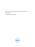
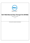
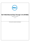
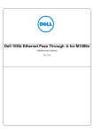
Dell PowerEdge M1000e:
PowerConnect M6220 Switch Stacking Use Case Guide
By Bo Griffin, Richard Horton, and Jason Pearce
Glossary ...............................................................................................................................................................1
What is stacking? .................................................................................................................................................2
Why stack?...........................................................................................................................................................2
PowerEdge M1000e Modular Chassis IOM Fabric Overview..............................................................................3
Initial Stack Configuration ....................................................................................................................................7
Common Use Cases ............................................................................................................................................9
Stacking Modular Switches for Higher Server Throughput .............................................................................................. 9
Stacking Modular Switches for Increased Server Availability......................................................................................... 10
Stacking Modular Switches for Server Virtualization...................................................................................................... 11
Summary ............................................................................................................................................................13
The Dell PowerConnect M6220 is a key component of the FlexIO architecture of the
M1000e Modular Server Enclosure. FlexIO delivers a level of IO flexibility, bandwidth,
features, and investment protection unrivaled in the blade server market. The M6220 is a
break-through modular design that packages a high-performance 24-port stackable
Ethernet switch with modular bays that can be populated with 10GbE or stacking modules
to provide customers with the flexibility to create exactly the switch they need for their
environment. One of the most powerful features of the M6220 is the ability to stack multiple
switches together, thereby creating a single logical switch that can be managed and
configured as one. This stacking capability is especially powerful when combined with the
ability to uplink to the Ethernet core via high bandwidth 10GbE connections. This White
Paper describes the basics of stacking, a description of the hardware and architecture,
configuration hints, and some sample use cases.
Glossary
CMC - “Chassis Management Controller”; the management interface for the
M1000e Modular Server Enclosure
GbE - “Gigabit Ethernet”
10GbE - “10 Gigabit Ethernet”
IOM - “I/O Module”; a module installed in the back of the PowerEdge M1000e
enclosure, such as an Ethernet pass-through, Ethernet switch, Fibre
Channel switch, or other communication fabric device
LACP - “Link Aggregation Control Protocol”; protocol for creating a single logical
network link by combining multiple physical links.
LAG - “Link Aggregate Group”; a group of switch ports that are placed into the
same channel group, often used with the 802.3ad protocol
LOM - “LAN-on-Motherboard”; a networking card integrated into the system board
of the server; while it may be possible to disable a LOM through BIOS
Setup, it is not possible to physically remove a LOM from the system
© Dell, Inc.
Mezzanine An I/O card that plugs into the server blade system board to add additional
Card- I/O connectivity; for example, an Ethernet controller or Fibre Channel host
bus adaptor; the Mezzanine Card is analogous to a PCIe card in a
monolithic server.
NIC - “Network Interface Controller”; a networking adapter (card)
Switch ID - Enumerated identification number of a switch in the stack
Stacking - Keep reading…
What is stacking?
Switch stacking is a feature that allows up to 12 interconnected PowerConnect M6220
switches to operate as though they are one switch. All switches in a stack share a single
management console and forward packets between their ports as a single switch. A
stacked set of switches appear to all external connections to be one switch.
A common misunderstanding is that a stacking port shares the same function as an uplink
port on an Ethernet switch. Many Ethernet switches, including the PowerConnect M6220,
have designated uplink ports that may operate at a higher data rate than the internal ports
of the switch (e.g. 10GbE) and are used to connect to the customer's Ethernet network at a
faster data rate than the standard downlink ports of the switch. These uplink ports are
standard Ethernet protocol ports that can connect to any other compatible Ethernet device
on your network. Stacking ports, however, are not standard Ethernet protocol ports and
instead allow multiple switches, when stacked, to behave as a single switch. To utilize the
stacking capability, stacking ports must connect to other stacking ports on the same type of
switch in order to function. The PowerConnect M6220 delivers stacking via an optional
stacking module in the optional bays (see Figure 1, page 3) and can only stack with other
M6220 switches.
Why stack?
Up to 12 PowerConnect M6220 switches can be stacked, supporting as many as 240
gigabit Ethernet ports and 24 10GbE ports in one stack. All of the ports in the stack are
managed as if they are ports on a single switch from one management interface. Stacking
M6220 switches also reduces the number of required uplink connections and enables
802.3ad link aggregation with aggregated ports located on different switches in the stack.
This allows servers in a modular chassis to use 802.3ad teams without having to use
Ethernet pass-through modules and external gigabit Ethernet switches.
Benefits of Stacking
• Improved Manageability: All switches in the stack are managed as a single switch – all
configuration and management is done from a single switch in the stack.
•
Efficient Spanning Tree: The stack is viewed as a single switch by the Spanning Tree
Protocol.
© Dell, Inc.
2
•
Link Aggregation: Stacking multiple switches in a chassis allows an LACP NIC team
on a blade server to link to a single logical switch across ports on different switches in
the stack.
•
Reduced Network Traffic: Traffic between the individual switches in a stack is passed
across the stacking cable, reducing the amount of traffic passed upstream to network
distribution switches.
•
Higher Speed: The stacking module supports a higher data rate than the 10GbE uplink
module – 48Gb aggregate throughput with the stacking module versus 40Gb aggregate
throughput with the 10GbE uplink module. (Note: Stack ports will not link with Ethernet
ports.)
•
Lower Cost: Uplink ports are shared by all switches in the stack, reducing the number
of distribution switch ports necessary to connect modular servers to the network.
•
Simplified Updates: The basic firmware management commands will propagate new
firmware versions and boot image settings to all switch stack members. The 62xx User
Guides have good descriptions of this process and user options. (Note: The
management interface will be inaccessible while the new firmware propagates through
the stack.)
PowerEdge M1000e Modular Chassis IOM Fabric Overview
The PowerEdge M1000e Modular Chassis includes six Input/Output Module (IOM)
interface slots divided into three fabrics, as shown in Figure 1, below.
Note: the IOM slots are labeled A1,
A2, B1, B2, C1, and C2 as can be
seen labeled on the rear of the
chassis. The CMC enumerates the
IOMs themselves as Modules 1-6 for
management purposes.
Figure 1 - M1000e Chassis Rear View
© Dell, Inc.
3
IOM slots A1 and A2 correspond to Fabric A. Fabric A connects to the two integrated
Ethernet controllers on each server motherboard (LOM 1 and LOM 2). IOM slots B1 and
B2 correspond to Fabric B. Fabric B connects to the dual-port mezzanine card B on each
server. IOM slots C1 and C2 correspond to Fabric C. Fabric C connects to the dual-port
mezzanine card C on each server. The mezzanine card B and C are located on the server
blade as shown in Figure 2, below.
Figure 2 - PowerEdge M600 (Shown with Two Optional I/O Mezzanine Cards Installed)
*Note: The AMD-based PowerEdge 605 modular server does not support GbE on Fabric C.
Figure 3 below illustrates how server blade ports are connected through the chassis
midplane to the IO modules in the rear of the chassis and how the chassis I/O slot
numbering scheme applies (i.e. A1-B1-C1-C2-B2-A2). Each port on a server blade is
hardwired through the chassis midplane to the server's corresponding port on each IO
module.
© Dell, Inc.
4
Figure 3 - Server-to-Switch Port Topology
Since Fabric A is connected to the LOMs, its I/O fabric type is always Gigabit Ethernet.
Fabrics B and C can accept several different types of I/O mezzanine cards in the modular
servers and I/O modules in the IOM slots.
Fabric I/O type is set by the first mezzanine card or IOM that is present in a fabric. If a
mezzanine card is mistakenly added to a server that does not match the I/O type of the
fabric it connects to, then that server will not be allowed to power on and the CMC will
report an I/O mismatch error. Also, a modular switch will not power on when inserted into
an IOM slot with a non-matching fabric I/O type. The CMC CLI commands getdcinfo and
getioinfo will help in resolving these situations.
Each IOM slot in the M1000e modular chassis connects to the same adapter on all 16
modular servers in the chassis. For example, IOM slot A1 connects to the first LOM on
each server, IOM slot A2 to the second LOM, IOM slot B1 connects to the first adapter on
each server’s mezzanine card B, and so on. Therefore, each modular switch has 16
internal ports that each connect to a single adapter on one of the chassis’ 16 modular
servers. The internal ports of the switch each connect to the corresponding server number
in the chassis. That is, Port 1 on a modular switch connects to server 1 in the chassis, port
2 to server 2, and so on.
© Dell, Inc.
5
The M6220 switch also has four external 10/100/1000Mb Ethernet ports and two external
option module bays for 10GbE uplink or stacking modules, as shown in Figure 4.
Figure 4 - PowerConnect M6220
The four external gigabit Ethernet ports have standard 10/100/1000Base-T connectors, but
the external option module bays require a 10GbE or stacking module. Each module bay
accepts a dual-port 10GbE uplink module. Module bay 1 will also accept a dual-port
stacking module, as shown in Figure 5.
Figure 5 - PowerConnect M6220 with One 10-Gb Uplink Module and One Stacking Module
As with other components in the M1000e chassis, System Management information for
installed M6220 IOM’s may be viewed through the CMC web interface. Figure 6, below,
shows an image of a typical IOM status screen viewed with a web browser. In addition to
indicating general I/O module status, the Slot numbers are shown, paired by fabric letter.
Figure 6 – CMC Web Interface I/O Module Status Screen
© Dell, Inc.
6
Initial Stack Configuration
To configure M6220 switches for stacking, install a stacking module into module bay 1 of
each switch, per Figure 5 (and a 10GbE uplink module into bay 2 if desired). Then insert
the switch into the desired IOM slot in the M1000e modular chassis, per Figure 5.
Here are the key steps. Before connecting any uplink or stacking cables, configure each
switch to a unique switch ID. If the switches are not manually configured, each switch will
be assigned to the lowest available ID number as the switches are added to the stack.
Manually configuring the switches removes any uncertainty as to how the switches are
numbered – this step is for convenience, but is not required. To assign a switch to an ID
use the following commands in the switch CLI. The switch CLI can be easily reached via
the external console port, the switch GUI, or via the CMC CLI connect switch-n
command. For example, in the CLI, use the following command sequence:
console> enable
console# configure
console(config)# switch 1 renumber 2
Using the above command will renumber Switch 1 to Switch 2. The available ID range is
from 1 to 12 (1 is the default ID) and each switch must have an ID that is unique within the
stack. Using the show switch command in the switch CLI normal mode will show the
switch’s current ID. A switch’s assigned ID will stay with the switch even without saving the
switch’s configuration. Once each switch has been assigned a unique ID for the stack, the
switches can be physically cabled to create the stack.
Cabling: M6220 switches should be stacked together by connecting a stacking cable from
stack port xg2 of one switch to stack port xg1 of the next switch. The stacking cable is
included with the stacking module. Stack port xg2 of the final switch in the stack should be
connected to stack port xg1 of the first switch, completing the stack loop. A loop topology
is not strictly required for a stack but it is recommended, as it is the most robust stacking
topology and has seen the most time in production use.
Stack Master Election: Once PowerConnect M6220 switches are stacked together, the
stacked switches elect one switch in the stack to be the Stack Master. A switch that is not
in a stack is, in effect, a Stack Master of a single-switch stack. The Stack Master in an
M6220 stack can be visually identified by the illuminated blue LED on the IOM, located just
beneath the serial console connector. The other stack members will not illuminate their blue
LEDs. When a switch joins a stack as a member, it will turn off its blue LED. Also, the
console of a stacked switch that is not the stack master indicates the ID of the current
Stack Master by printing a message similar to the following:
(Unit 1 - CLI unavailable - please connect to master on Unit 2)>
M6220 switches support up to 12 switches in a stack. Switches in a stack may be located
in the same or in different M1000e modular chassis. However, the PowerConnect M6220
cannot be stacked with other PowerConnect switch models or with other vendor’s switches.
© Dell, Inc.
7
OOB Management Connection: The out-of-band management interfaces (both serial and
Ethernet) will only be accessible on the Stack Master. To reiterate, only the Stack Master
can be managed via serial connection – it will be the only switch with out-of-band
management connectivity. As a useful reminder, the blue LED next to the serial console
port will only be illuminated on the Stack Master.
Rigging the Election: If it is desirable to designate which switch in the stack should be
elected as the Stack Master, use the following commands in the switch CLI to set that
switch to the highest priority.
console> enable
console# configure
console(config)# switch 1 priority 12
The above commands set Switch 1 in the stack to priority 12, which is the highest priority.
Setting another switch to priority 11 will make it the Standby Switch in the stack. The
Standby Switch synchronizes with the Stack Master to keep a copy of the stack’s running
configuration up-to-date. The Standby Switch will become the new Stack Master in the
event that the current Stack Master fails. If switch priorities are not set, or if they are set to
the same value, master and standby switches will be elected by switch MAC address.
Changing the priority of switches in a stack will not immediately change which switch is the
stack’s current master.
Changing the Stack Master: To change the Stack Master of an active M6220 stack, run
the following commands in the switch CLI:
console> enable
console# configure
console(config)# stack
console(config-stack)# movemanagement 2 1
Note: Running this command will interrupt the management session and any
switch traffic, and requires connecting to the new Stack Master to continue
managing the stack.
Using the above commands, the Stack Master is changed from Switch 2 to Switch 1. As
the new Stack Master comes up it will also elect a new Standby Switch according to switch
priorities.
Designating the Standby Switch: To change which switch is the Standby Switch in an
active stack run the following commands in the switch CLI:
console> enable
console# configure
console(config)# stack
console(config-stack)# standby 3
These commands reconfigure the stack such that Switch 3 becomes the stack’s new
Standby Switch switch. Switch 3 will then be synchronized with the current stack
© Dell, Inc.
8
configuration by copying the configuration data from the Stack Master. In the event of a
Stack Master failure, Switch 3 will take over as Stack Master.
Port Management: Once an M6220 switch stack is cabled together and a Stack Master
has been elected, all switch management is performed via the Stack Master. Port
configuration commands reference individual ports using the Switch ID and the port
number. For example, the following commands would add port 12 on switches 3 and 4 to
channel-group 12, using 802.3ad link aggregation:
console> enable
console# configure
console(config)# interface ethernet 3/g12
console(config-if-3/g12)# channel-group 12 mode auto
console(config-if-3/g12)# exit
console(config)# interface ethernet 4/g12
console(config-if-4/g12)# channel-group 12 mode auto
Common Use Cases
Stacking Modular Switches for Higher Server Throughput
As mentioned above, the ability to configure multiple M6220 switches into a stack provides
high-throughput server communication through member switches. Stacking M6220
switches within the same M1000e modular chassis enables the use of LACP-configured
link aggregation groups (LAGs) between the switch stack and the modular chassis’ servers.
LACP allows all of the members of the links in a LAG to send and receive traffic
simultaneously as one logical connection. A four-link LACP LAG can provide up to four
times the bandwidth of a single link for both sending and receiving. Compared to alternate
methods of teaming a server’s NICs, LACP provides better throughput performance and
simpler link redundancy.
As shown in the Figure 7, cabling a M6220
switch stack for high server throughput is simple.
Using stacking cables connect port xg2 of the
stacking module of each switch to port xg1 of the
stacking module of the neighboring switch and
connect the first and last switch in the stack to
complete the loop.
This cabling scheme allows the prime benefit of
stacking for increased throughput to be realized.
The uplink connection from one switch in the
stack will forward network traffic from all of the
other switches in the stack. This configuration
also will allow for a reduction in the number of
uplinks that need to be connected to the stack.
Figure 7 – Stacking for High Throughput
Reducing the number of required uplinks can
© Dell, Inc.
9
significantly reduce the total cost of ownership (TCO) by reducing the number of expensive
10GbE switch ports that would be consumed on the network’s distribution switches. For
example, the stack shown in Figure 7 only requires a single uplink to connect every switch
in the M1000e modular chassis to the network, although additional uplinks may be
desirable for improved performance and/or reliability. If the switches were not stacked,
each switch would require a discreet uplink just to provide connectivity.
There is no requirement that stacked switches be installed in the same chassis. Up to
twelve M6220 switches can be stacked and each switch in a stack could be in a separate
chassis if desired. However, the M6220 switch stack only supports eighteen concurrent
LAGs, while the M1000e modular chassis can house as many as sixteen server blades.
When using LACP for server NIC teams, the M6220 switch stack’s functional coverage may
be limited to one modular chassis.
Stacking Modular Switches for Increased Server Availability
To ensure maximum uptime of network
resources, servers should be connected to the
network via fully redundant paths. Each server
should connect to at least two logically discreet
switches, and each of the switches should
connect separately to the network. In this case,
stacking switches within a chassis is not as
useful as in the prior example. However,
stacking switches across multiple chassis can be
very beneficial. When a stack spans across two
or more chassis, the number of required uplinks
per server can be greatly reduced, minimizing
TCO. Also, network and application performance
gains may be realized by allowing peer-to-peer
network traffic between servers connected to the
same switch stack to transit across the stack
without passing through the distribution
switches.
Figure 8 shows two M6220 switch stacks
deployed across two chassis. Each switch stack
should have its own set of uplinks to the same
distribution switches as the other switch stack.
Each server should have a teamed pair of
Ethernet ports configured for switch fault
tolerance, with one port connected to each
stack. The pair of stacks should be configured
with the same connectivity to the servers and to
the distribution switches upstream.
As shown in Figure 8, the switch stacks have
only two switches per stack, allowing for Figure 8 – Stacking for High Availability
© Dell, Inc.
10
expansion to as many as twelve M1000e modular chassis. Expanding the configuration to
its limit will allow a single switch stack to connect as many as 192 modular servers.
Alternatively, more than one switch per chassis could be included in each stack, increasing
the number of NICs capable of participating in each switch fault tolerant team. Depending
on the particular type of teaming used, a performance improvement may also be realized.
Should switch or uplink connectivity be interrupted in one of the stacks, the switch fault
tolerant teams on the servers provide a means for network traffic to automatically move
from one stack to the other. Also, should one of the stack’s Master Switches fail, traffic will
immediately migrate to the other stack, eliminating the delay that could possibly occur in a
single stack configuration.
Cabling for the Increased Server Availability scenario is similar to that used in the Higher
Server Throughput example above, except here, two stacks are created with one switch
per stack in each chassis. One stack is created from modular switches on the left side of
the M1000e chassis, and the other stack is created from switches on the right side of the
chassis.
Caution: Duplicate IP Addresses If this example is modified to include multiple switches
per chassis in a stack that spanned across multiple chassis, it is best to keep the switch
stack from looping more than once through any participating chassis. If this practice is not
followed, then one chassis shutting down will break the stack loop twice and divide the
stack into two separate switch stacks. This will cause unexpected behavior, as the separate
stacks will have the same configuration and may cause connectivity conflicts, such as
duplicate IP addresses.
Increasing the number of switch stacks present per chassis -- from the two in this example
to four -- is a modification that could noticeably improve server connectivity uptime. Switch
fault tolerant teaming provides better uptime when three or four NICs are used in a team
with each connected to a redundant switch.
To further improve the level of network availability provided in this example, each switch
stack should uplink to multiple redundant distribution switches. Where possible, the uplinks
should connect to different switches within the stack, which will prevent the failure of one
stack member from causing a traffic outage to all members of the stack. As long as the
servers’ NIC team members are connected to fully redundant network paths, any single
point of failure will not interrupt network service to the modular servers. If an adapter fails,
the other adapter in its switch fault tolerant team can maintain connectivity. If a switch fails,
not only will the rest of the stack continue to function, but the servers attached to the failed
switch will remain connected through the other switch stack.
Stacking Modular Switches for Server Virtualization
For some applications, users want completely separate network connectivity for different
types of traffic. For example, with server virtualization, it is often desirable to isolate virtual
host management, virtual guest migration, and virtual guest user traffic onto different
physical connections. The example in Figure 9 uses multiple M6220 switch stacks across
two M1000e modular chassis to provide physically separated network traffic.
© Dell, Inc.
11
The two switch stacks on the left side of Figure 9 (shown with blue and red cables) are
composed of one switch per chassis. The first stack uses the switches in the IOM A1 slots
of each M1000e modular chassis, and the second stack uses the switches in the IOM A2
slots. These two stacks are designated to be
used for virtual host management and virtual
guest migration, respectively. Virtual host
management and virtual guest migration will
have low upstream bandwidth requirements, so
these stacks will require only a pair of gigabit
uplinks each, greatly improving TCO. Virtual
guest migration performance will also benefit
from the high-speed inter-switch bandwidth
afforded by the stacking modules. Both of these
stacks could be extended across as many as
twelve chassis, connecting up to 192 modular
servers.
The other switch stacks in this example, shown
in the right side of Figure 9 with green cables,
are composed of the two switches in each
chassis’ IOM B2 and A2 slots. These stacks are
designated for virtual guest user traffic and will
be configured with LACP-enabled LAGs to all 16
of each chassis’ modular servers. As with the
High Server Throughput example, each of these
stacks can only effectively support a single
M1000e modular chassis. These stacks will also
require higher upstream bandwidth than the
leftmost two stacks since most upstream
network traffic from the chassis will be generated
by virtual guest applications.
In this
configuration, a pair of 10GbE uplinks will
suffice. One uplink will be attached to each
switch in a stack. This will allow for optimal
continued performance in the event of a switch
failure. There are four 10GbE uplinks available,
allowing room for increased uplink throughput
Figure 9 – Stacking for Virtualization
However, for this example, two 10GbE uplinks
per stack is sufficient.
The switches in IOM slots C1 and C2 provide multi-path connectivity to shared storage in a
storage area network (SAN) using mezzanine card C in each server. Further discussion of
the SAN configuration is beyond the scope of this paper.
Because the first two switch stacks are physically separate from the others, this
configuration provides discreet connectivity that will keep the different types of traffic
© Dell, Inc.
12
isolated. Stacking in this application provides two distinct advantages over a non-stacked
solution:
(1) The configuration reduces the number of uplinks from the chassis to the network
used for host management and guest migration without impacting these function’s
performance. Host management and guest migration require less upstream
bandwidth, so it is possible to consolidate the upstream traffic for a stack onto just 1
or 2 GbE uplinks. The guest migration stack especially benefits from this reduced
uplink cost. Also, its requirement for high peer-to-peer bandwidth between servers
connected to the same stack is not impeded by the use of inexpensive, slower
uplinks.
2) The switch stacks used for virtual guest user traffic (rightmost stacks, shown in
green) in each chassis will provide LACP teaming for performance-optimized
connectivity to the modular servers to meet the high bandwidth demands of the
virtual guest user traffic. The user traffic has high upstream bandwidth requirements,
so the uplinks for these stacks are more expensive than those used for the host
management or guest migration stacks. Fortunately, the higher expense is applied
directly to improving guest application performance, which yields the greatest benefit
to server virtualization.
Summary
These are just a few possible applications of using the stacking functions of the
PowerConnect M6220 Ethernet switch. After reading this White Paper, the reader should
be able to configure an M6220 switch stack and have a better understanding of the
application of stacking strategies in modular server deployments. Examination of specific
customer requirements and circumstances will reveal many other possibilities where switch
stacking can be used to enhance networking functions. The benefits of stacking are not
limited to the examples given here. To truly realize the full redundancy, throughput and
TCO benefits of stacking Dell PowerConnect M6220 switches, discuss the configuration
and application with your qualified Dell Sales Team, Dell Product Engineers, and other Dell
Consultants.
© Dell, Inc.
13