1
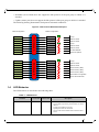
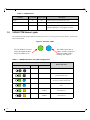
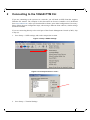
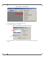
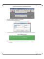
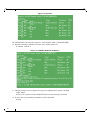
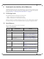
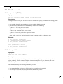
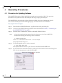
Dell 10Gb Ethernet Pass Through -k for M1000e
Software User’s Manual
Rev 1.00
This document is intended for administrators.
Rev 1.00
____________________
Information in thisSXEOLFDWLRQsubject to change without notice.
© 2011 Dell Inc. All rights reserved.
Reproduction of these materials in any manner whatsoever without the written permission of Dell Inc. is strictly forbidden.
Trademarks used in this text: Dell™, the DELL logo, and PowerEdge™ are trademarks of Dell Inc.
Other trademarks and trade names may be used in this publication to refer to either the entities claiming the mark and names or their products.
Dell Inc. disclaims any proprietary interest in trademarks and trade names other than its own.
January 2011 Rev: A00
2
Document Number: 3257
Rev 1.00
Table of Contents
About this Manual . . . . . . . . . . . . . . . . . . . . . . . . . . . . . . . . . . . . . . . . . . . . . . . . . . . . . . . . . . . . . . . . 5
Intended Audience . . . . . . . . . . . . . . . . . . . . . . . . . . . . . . . . . . . . . . . . . . . . . . . . . . . . . . 5
Related Documentation . . . . . . . . . . . . . . . . . . . . . . . . . . . . . . . . . . . . . . . . . . . . . . . . . . 5
Terms, Abbreviations and Conventions . . . . . . . . . . . . . . . . . . . . . . . . . . . . . . . . . . . . . . 5
Chapter 1
Overview . . . . . . . . . . . . . . . . . . . . . . . . . . . . . . . . . . . . . . . . . . . . . . . . . . . . . . . . . . . . . 6
1.1
1.2
1.3
1.4
1.5
Port Groups . . . . . . . . . . . . . . . . . . . . . . . . . . . . . . . . . . . . . . . . . . . . . . . . . . . . . . . 6
Port Link State Reflection . . . . . . . . . . . . . . . . . . . . . . . . . . . . . . . . . . . . . . . . . . . 6
Link Protocol Mismatch Condition . . . . . . . . . . . . . . . . . . . . . . . . . . . . . . . . . . . . 6
LED Behavior . . . . . . . . . . . . . . . . . . . . . . . . . . . . . . . . . . . . . . . . . . . . . . . . . . . . . 7
10GbE PTM Status Lights . . . . . . . . . . . . . . . . . . . . . . . . . . . . . . . . . . . . . . . . . . . 8
Chapter 2
Connecting to the 10GbE PTM CLI . . . . . . . . . . . . . . . . . . . . . . . . . . . . . . . . . . . . . . 9
Chapter 3
Command Line Interface (CLI) Reference . . . . . . . . . . . . . . . . . . . . . . . . . . . . . . . . 13
3.1
3.2
3.3
3.4
3.5
3.6
3.7
3.8
Chapter 4
Operating Procedures . . . . . . . . . . . . . . . . . . . . . . . . . . . . . . . . . . . . . . . . . . . . . . . . . 22
4.1
Chapter 5
CLI Privilege Levels . . . . . . . . . . . . . . . . . . . . . . . . . . . . . . . . . . . . . . . . . . . . . . . 13
Quick Reference . . . . . . . . . . . . . . . . . . . . . . . . . . . . . . . . . . . . . . . . . . . . . . . . . . 13
CLI Command Reference Conventions . . . . . . . . . . . . . . . . . . . . . . . . . . . . . . . . 14
General Commands . . . . . . . . . . . . . . . . . . . . . . . . . . . . . . . . . . . . . . . . . . . . . . . 14
3.4.1 help . . . . . . . . . . . . . . . . . . . . . . . . . . . . . . . . . . . . . . . . . . . . . . . . . . . . . . 14
3.4.2 login (ADMIN) . . . . . . . . . . . . . . . . . . . . . . . . . . . . . . . . . . . . . . . . . . . . . 15
3.4.3 exit . . . . . . . . . . . . . . . . . . . . . . . . . . . . . . . . . . . . . . . . . . . . . . . . . . . . . . . 15
3.4.4 reload . . . . . . . . . . . . . . . . . . . . . . . . . . . . . . . . . . . . . . . . . . . . . . . . . . . . . 15
Software Update Commands . . . . . . . . . . . . . . . . . . . . . . . . . . . . . . . . . . . . . . . . 16
3.5.1 show image ver . . . . . . . . . . . . . . . . . . . . . . . . . . . . . . . . . . . . . . . . . . . . . 16
3.5.2 copy image from-file . . . . . . . . . . . . . . . . . . . . . . . . . . . . . . . . . . . . . . . . . 16
Device Commands . . . . . . . . . . . . . . . . . . . . . . . . . . . . . . . . . . . . . . . . . . . . . . . . 17
3.6.1 show device temp (ADMIN) . . . . . . . . . . . . . . . . . . . . . . . . . . . . . . . . . . 17
Port Commands . . . . . . . . . . . . . . . . . . . . . . . . . . . . . . . . . . . . . . . . . . . . . . . . . . 18
3.7.1 set port test (ADMIN) . . . . . . . . . . . . . . . . . . . . . . . . . . . . . . . . . . . . . . . . 18
3.7.2 show port link . . . . . . . . . . . . . . . . . . . . . . . . . . . . . . . . . . . . . . . . . . . . . . 18
3.7.3 show port module . . . . . . . . . . . . . . . . . . . . . . . . . . . . . . . . . . . . . . . . . . . 19
3.7.4 show port test (ADMIN) . . . . . . . . . . . . . . . . . . . . . . . . . . . . . . . . . . . . . . 20
Debug Commands . . . . . . . . . . . . . . . . . . . . . . . . . . . . . . . . . . . . . . . . . . . . . . . . 20
3.8.1 cr_read (ADMIN) . . . . . . . . . . . . . . . . . . . . . . . . . . . . . . . . . . . . . . . . . . . 20
3.8.2 cr_write (ADMIN) . . . . . . . . . . . . . . . . . . . . . . . . . . . . . . . . . . . . . . . . . . 20
Procedure for Updating Software . . . . . . . . . . . . . . . . . . . . . . . . . . . . . . . . . . . . . 22
Troubleshooting . . . . . . . . . . . . . . . . . . . . . . . . . . . . . . . . . . . . . . . . . . . . . . . . . . . . . . 24
5.1
Resolving 10GbE PTM Power Problems . . . . . . . . . . . . . . . . . . . . . . . . . . . . . . . 24
3
Rev 1.00
Software User’s Manual
5.2
5.3
5.4
5.5
5.6
4
Resolving Link Connectivity Problems . . . . . . . . . . . . . . . . . . . . . . . . . . . . . . . . 24
Resolving a Link Protocol Mismatch . . . . . . . . . . . . . . . . . . . . . . . . . . . . . . . . . . 25
Resolving CLI Connectivity Problems . . . . . . . . . . . . . . . . . . . . . . . . . . . . . . . . . 25
Recovery From Non-Responsive 10GbE PTM CLI . . . . . . . . . . . . . . . . . . . . . . . 25
Recovery From a Software Update Failure . . . . . . . . . . . . . . . . . . . . . . . . . . . . . 25
Rev 1.00
About this Manual
This manual describes the installation and basic use of the Dell 10Gb Ethernet Pass Through -k
for M1000e.
Intended Audience
This manual is intended for users and system administrators responsible for installing and setting
up the I/O module.
Related Documentation
Additional documentation available is provided in Table 1.
Table 1 - Referenced Documents
http://support.dell.com/support/
Firmware Releases
Terms, Abbreviations and Conventions
Table 2 - Abbreviations and Convention
Term
Definition
IOM
I/O Module
PTM
Pass Through Module
Downlink
Internal link – from servers to 10GbE PTM PHY (through the mid plane connector)
Uplink
External link – from 10GbE PTM PHY to external link (typically connected to Ethernet switch)
SSH
Secure Shell (also refers to a software program that allows connectivity using an SSH protocol.)
CMC
Chassis Management Controller
Component
10GbE PTM PHY device
Component numbering
Components are numbered from one (1) to three (3).
When looking at the 10GbE PTM component side with external connectors (uplink) up, the components are numbered as follows:
Device number 1 is the right-most component
Device number 2 is the middle component
Device number 3 is the left-most component
Wherever applicable, device number 0 refers to the on-board micro-controller
5
Rev 1.00
1
Software User’s Manual
Overview
This manual explains the use of the embedded software management of the 10GbE PTM. It
explains how to connect to the 10GbE PTM and to the CMC, and how to update the module and
device firmware and software.
This manual covers the following topics:
• The rest of this section provides a high-level overview of the I/O Module structure and capabilities
• Section 2, “Connecting to the 10GbE PTM CLI,” on page 9, explains how to connect to
the 10GbE PTM and issue CLI commands
• Section 3, “Command Line Interface (CLI) Reference,” on page 13 documents the CLI
• Section 4, “Operating Procedures,” on page 22 describes the detailed sequence of operations required to achieve tasks such as software update
1.1
Port Groups
The 10GbE PTM has 16 front panel ports divided into two groups: A and B. Group A consists of
ports 1 through 8, providing service to blades 1 through 8, respectively; Group B consists of ports
9 through 16, providing service to blades 9 through 16, respectively.
The supported link protocol for all internal ports is 10GBase KR
Figure 1 shows the front panel ports and their partitioning into Group A and Group B.
Figure 1: Front Panel Link Speed Port Groups
1.2
16
15
14
13
12
11
10
9
8
7
6
5
4
3
10 Gb Ethernet Pass Through -k
2
1
D
D
Port Link State Reflection
The 10GbE PTM reflects the link state from the uplink to the downlink. When an uplink port connected to a remote peer (e.g. an Ethernet switch) is disconnected, the respective server blade will
indicate link down event. When the uplink port is connected, the respective server blade will indicate link up.
1.3
Link Protocol Mismatch Condition
A port may enter a link protocol mismatch condition. When in this condition, the port links (both
uplink and downlink) will remain inactive. Mismatch condition is indicated by the port LEDs.
Additional information about the mismatch condition is available via the CLI. Link protocol mismatch would occur under the following conditions:
6
Rev 1.00
• Downlink (server blade) does not support the link protocol of the port group to which it is
attached
• Uplink (remote peer) does not support the link protocol of the port group to which it is attached
The following drawing demonstrates link protocol mismatch conditions:
Figure 2: Link Protocol Mismatch Examples
Blade Configuration:
Module Configuration:
KR
Port Group A
KX4
KX
KR
KX4
KX
Link up
SFP+ SR
Blade is not KR
SFP+ SR
Blade is not KR
SFP+ LR
Link up
SFP+ LR
Blade is not KR
SFP+ LR
Blade is not KR
No Cable
No cable detected
KX4
EMPTY
Module not present
KR
Passive Cable
Link up
Passive Cable
Blade is not KR
Passive Cable
Blade is not KR
KX4
Port Group B
KX4
KX
KR
KX4
KX
KX4
KX4
1.4
SFP+ SR
SFP
Module is SFP (1GbE)
SFP
Module is SFP (1GbE)
SFP
Module is SFP (1GbE)
SFP+ LRM
SFP+ LR, No Link
LRM module not supported
No link with remote side
LED Behavior
The LED behavior is described in the following table:
Table 3 - LED Behavior
Condition
Link down
Green LED
Amber LED
off
off
Description
This condition occurs in the following cases:
• Server blade not present, powered down, or link is
inactive
• Uplink port module not present
• Uplink port cable not connected
• One or both of the internal and/or external links is
down
7
Rev 1.00
Software User’s Manual
Table 3 - LED Behavior
Condition
1.5
Green LED
Amber LED
Link up
on
off
Data activity
on
blink
Link protocol mismatch
off
on
Description
Both the internal and external links are up
Link is up and data packets are sent or received
Refer to Section
1.3, “Link Protocol Mismatch Condition,” on page 6 for details.
10GbE PTM Status Lights
The 10GbE PTM Status lights indicate whether the switch is receiving power from the chassis, and the state
of the 10GbE PTM.
Figure 3: Indicator LEDs
This LED can be blue or
amber. A fault is indicated
when the amber LED is
blinking. See Table 4.
The I/O Module is on and
ready when both the blue
and green LEDs are lit.
Table 4 - 10GbE PTM states and LED configurations:
LED
10GbE PTM Status
Indication
8
Green
Status
OFF
OFF
OFF
ON
OFF
Boot in Progress
10GbE PTM not ready
ON
BLINKING BLUE
The CMC is identifying
the newly installed 10GbE PTM
ON
ON BLUE
10GbE PTM is on and operating Normally
ON
ON or BLINKING
AMBER
Fault in System
Self-diagnosed
OFF
ON or BLINKING
AMBER
Fault in System
CMC-detected
Rev 1.00
2
Connecting to the 10GbE PTM CLI
If you are connecting to the system over a network, you will need an SSH client that supports
ZModem file transfer. The examples in this document use Secure CommNet v2.35 (download
from www.radient.com). After you download the software, some initial configuration is necessary.
Please follow the next configuration steps; when using a different client software, similar settings
should be available.
If you are connecting directly to the serial port of the Chassis Management Console (CMC), skip
to step (9).
1. Go to Setup => SSH2 settings, and set the compression to none.
Figure 4: Setup > SSH2 Settings
Figure 5: Set Compression to “none”
2. Go to Setup => Terminal Settings
9
Rev 1.00
Software User’s Manual
Figure 6: Setup > Terminal Settings
3. Select Emulation type => SCOANSI/ANSI and VT100.
4. Select Backspace Character => Control-H
Figure 7: Set Emulation Type and Backspace Character
5. Go to Communications => Open SSH2 connection. This will open the SSH2 Connection dialog box.
10
Rev 1.00
Figure 8: Communications > Open SSH Connection
6. Fill in the hostname or IP address of your system.
7. Fill in the user name and the password.
Figure 9: Enter Hostname and Password
8. Your SSH connection will open. You will see a welcome banner and a user prompt (#)
Figure 10: SSH Connected
9. To list all the devices in the system, enter the following command:
# getioinfo
11
Rev 1.00
Software User’s Manual
Figure 11: getioinfo
The 10GbE PTM is listed by the system as “10Gb PT KR” "DELL 10GbE KR PTM".
10. Run the following command to connect to the 10GbE PTM CLI:
# connect switch-3
Figure 12: 10GbE PTM Welcome Banner
11. Change privilege level if required. To login as an administrator, run the command
login admin
You are now connected to the 10GbE PTM and can start entering commands.
12. To show the list of available commands, run the command:
# help
12
Rev 1.00
3
Command Line Interface (CLI) Reference
10GbE PTM management is done via the 10GbE PTM CLI. You can use the commands described
in this section after successfully connecting to the 10GbE PTM CLI according to the procedure
described in Section 2, “Connecting to the 10GbE PTM CLI,” on page 9.
3.1
CLI Privilege Levels
The 10GbE PTM supports the following user privilege levels:
• USER - Common user level, indicated by the # prompt
• ADMIN - Administrator level, indicated by the & prompt
Different commands are available in different privilege levels. The command reference indicates
the required privilege level for each command that requires a privilege level higher than USER.
3.2
Quick Reference
Table 5 provides a quick reference to the CLI commands:
Table 5 - List of Commands
Command
name
Short Description
Reference
General Commands
help
Shows the list of available commands
Section 3.4.1, “help,” on page 14
login
Change privilege level
Section 3.4.2, “login (ADMIN),” on
page 15
exit
Exit current privilege level
Section 3.4.3, “exit,” on page 15
reload
Restart the module:
Hardware reset and software reload
Section 3.4.4, “reload,” on page 15
Software Image Commands
show image ver
Shows the software image version
copy image from- Upload new software image to the PTM
file
Section 3.5.1, “show image ver,” on
page 16
Section 3.5.2, “copy image from-file,”
on page 16
Device Commands
show device temp Shows the temperature of a specified device
Section 3.6.1, “show device temp
(ADMIN),” on page 17
Port Commands
13
Rev 1.00
Software User’s Manual
Table 5 - List of Commands
Command
name
Short Description
Reference
set port test
Sets port test mode attributes
Section 3.7.1, “set port test
(ADMIN),” on page 18
show port link
Shows port link state
Section 3.7.2, “show port link,” on
page 18
show port module Shows uplink module parameters
Section 3.7.3, “show port module,” on
page 19
show port test
Shows ports test mode status
Section 3.7.4, “show port test
(ADMIN),” on page 20
cr_read
To read a 32 bit register from device number device_num.
Section 3.8.1, “cr_read (ADMIN),” on
page 20
cr_write
To write a data_dword to address
0xHex_address to device number
device_num.
Section 3.8.2, “cr_write (ADMIN),”
on page 20
Debug Commands
3.3
CLI Command Reference Conventions
This section describes the PTM CLI commands.
For each command, the following information is provided:
• Synopsys:
Lists the command name and any required or optional parameters. Variable parameters (like port
numbers) are shown in italics. Optional parameters are shown in square brackets, e.g.
[optional_parameter]. Required parameters are shown with no brackets.
• Description:
Provides a detailed description of the command and of all its parameters
• Example:
Usage example and command output.
• For purpose of automation, the symbol ‘#’ is used to indicate a comment that extends until the
next new-line character.
3.4
General Commands
3.4.1 help
Synopsys:
help
14
Rev 1.00
Description:
Show the list of all available commands.
ADMIN: when in ADMIN mode, this command will also show commands that require ADMIN
privilege level.
Example:
# help
Commands list:
?
help
copy image from-file
...
#
Show this help message
Show this help message
Upload new software image to the PTM
3.4.2 login (ADMIN)
Synopsys:
login user|admin
Description:
Change the privilege level. The user is required to login to the CLI before any operations take
place.
Example:
# login user
# login admin
&
3.4.3 exit
Synopsys:
exit
Description:
Exit current privilege level.
Example:
& exit
3.4.4 reload
Synopsys:
reload
15
Rev 1.00
Software User’s Manual
Description:
Use this command to restart the module components. When this command is issued, PTM components go through a full hardware reset, followed by software reload.
Options:
• device_number: specify a single device to reset
Example:
$ reload
3.5
Software Update Commands
3.5.1 show image ver
Synopsys:
show image ver
Description:
Display the current software image version.
ADMIN: This command also displays the firmware version of each component.
Example:
# login admin
& show image ver
Software image short version: V Z.ZZ
Software image version: X.X.XXX-<date stamp>
Component #1 firmware version: Y.Y.YYY
Component #2 firmware version: Y.Y.YYY
Component #3 firmware version: Y.Y.YYY
& login user
3.5.2 copy image from-file
Synopsys:
copy image from-file [device_number]
Description:
Update the firmware the PTM software image. In ADMIN mode, it allows selective upgrade of a
single device in the PTM. Immediately after running this command, the CLI waits for the user to
send the firmware image using the ZModem protocol. To abort this operation, use CTRL-C. For
additional details on the firmware update procedure refer to Section 4, “Operating Procedures,”
on page 22.
ADMIN:
16
Rev 1.00
• device_number: device number onto which to upload the image
(0..3, where 0 indicates micro-controller image)
Example:
#
#
&
&
#
3.6
copy image from-file
login admin
copy image from-file 2
login user
# Update image on device no. 2
Device Commands
3.6.1 show device temp (ADMIN)
Synopsys:
show device temp device_number
Description:
Show the temperature of the specified device:
• device_number: device number from which to read temperature (1..3)
Example:
& show device temp 1
Device no. 1 temperature: 42 [Celsius]
&
17
Rev 1.00
3.7
Software User’s Manual
Port Commands
3.7.1 set port test (ADMIN)
Synopsys:
set port test port_number [prbs31 on|off|start|stop]
Description:
Configure test mode on a port. Test mode is used to measure link quality and calibrate link tuning parameters.
• port_number: downlink port number on which to enable / disable test mode
• prbs31: industry-standard pseudo-random binary sequence for link tuning
- prbs31 on: move the port to test mode
- prbs31 start: initalize prbs31 mechanism and start error counting
- prbs31 stop: terminate prbs31 error counting
- prbs31 off: move the port back to operational mode
Note: After “prbs31 on” and before “prbs31 start”, configure prbs31 on the remote peer.
Example:
& set port test 6 prbs31 on
& # enable prbs31 on remote peer now
& set port test 6 prbs31 start
& show port test 6
port 6 prbs31 on: 0 errors
& set port test 6 prbs31 stop
& set port test 6 prbs31 off
3.7.2 show port link
Synopsys:
show port link [port_number]
Description:
This command displays detailed port information. If an uplink port number is specified
([port_number]), then the command displays information only for this port; otherwise, the command displays information for all the ports.
The command displays the following information per port:
• Port number
• Port group identifier and speed: A, B, followed by the configured speed (10G)
• Pass through connection status, may have one of the following values:
down - either uplink or downlink is not connected
18
Rev 1.00
mismatch - both uplink and downlink are connected, but there is a mismatch
10G - uplink and downlink are connected at 10GbE
• Downlink port link state:
- down: blade not present
- 10G: 10GbE link
• Detailed downlink port link states (available in ADMIN level only):
- 10G KR [AN]: 10GBASE-KR link;
AN indicates that 802.3ap autonegotiation is active
• Uplink port link state:
- empty: No module present
- module_type [no link]: Module is present (module type is shown);
no link: optical fiber cable is disconnected
Example:
# show port link
Port Group
Connect
Downlink
Uplink
Status
-------------------------------------------------------------1
A (10G)
10G
10G
SFP+ SR
Link Up
2
A (10G)
10G
10G
SFP+ SR
Link Up
3
A (10G)
10G
10G
SFP+ LR
Link Up
4
A (10G)
10G
10G
SFP+ SR
Link Up
5
A (10G)
10G
10G
SFP+ SR
Link Up
6
A (10G)
mismatch
10G
SFP SX
Link Down
7
A (10G)
down
down
SFP+ SR
Link Down
8
A (10G)
down
down
empty
9
B (10G)
mismatch
10G
SFP SX
Link Down
10
B (10G)
mismatch
10G
SFP SX
Link Down
11
B (10G)
mismatch
10G
SFP SX
Link Down
12
B (10G)
mismatch
10G
SFP LX
Link Down
13
B (10G)
down
down
empty
14
B (10G)
down
10G
SFP+ SR
Link Down
15
B (10G)
mismatch
1G
SFP+ SR
Link Down
16
B (10G)
mismatch
1G
SFP+ SR
Link Down
#
# show port link 7
Port Group
Connection Downlink
Uplink
Status
-------------------------------------------------------------7
A (10G)
down
down
SFP+ SR
Link Down
#
3.7.3 show port module
Synopsys:
show port module port_number
Description:
Show the transceiver module information for the specified uplink port.
19
Rev 1.00
Software User’s Manual
Example:
# show port module 1
Status.........................................
Gigabit Ethernet Compliance Codes..............
Vendor Name....................................
Vendor Part Number.............................
Vendor Serial Number...........................
Vendor Revision Number.........................
#
OK
10GBASE-SR
FINISAR CORP.
FTLX8571D3BCL-ME
UDD01@A
A
3.7.4 show port test (ADMIN)
Synopsys:
show port test port_number
Description:
Show test mode on the specified downlink port port_number.
Example:
& show
port 4
& show
port 6
3.8
port test 4
test off
port test 6
prbs31 on: 0 errors
Debug Commands
3.8.1 cr_read (ADMIN)
Synopsys:
cr_read device_number 0xaddress [number_of_registers]
Description:
Read one or more internal PhyX device register. This command accepts the following parameters:
• device_number – the device from which to read a register (1..3)
• address – the register memory location from which to read (32-bit address)number_of_registers
(Optional) - Specifies the number of registers to read (default 1)
Example:
• & cr_read 2 0xf0014
0x000f0014:0x00a217d4
3.8.2 cr_write (ADMIN)
Synopsys:
cr_write device_number 0xaddress 0xdata
20
Rev 1.00
Description:
Write data to an internal register on a PhyX device. This command accepts the following parameters:
• device_number – the device to which memory the data should be written
• address – memory location of the internal register (32-bit address)
• data – the data to be written to the internal register
Example:
cr_write 1 0xf0010 0x1
21
Rev 1.00
Software User’s Manual
4
Operating Procedures
4.1
Procedure for Updating Software
The 10GbE PTM consists of three PhyX® devices and a micro-controller (CPU). This procedure
describes how to update both CPU SW & PhyX® FW using a single .pfw binary file.
The 10GbE PTM is delivered with the latest firmware available at the time of production. New firmare versions will be posted on the Dell support page. The latest firmware can be found at:
http://support.dell.com/support/
Step 1
Step 2.
Download the 10GbE PTM firmware .zip file and extract the .pfw binary file.
Connect to the 10GbE PTM using an SSH Client as described in Section 2, “Connecting to
the 10GbE PTM CLI,” on page 9.
Step 3.
Note:
From the CMC command line, connect to the 10GbE PTM CLI. Enter:
At least 20 seconds must have passed since the last power cycle of the 10GbE PTM
module before running the following connect command.
$ connect switch-<n>
where <n> is the number of the switch -- 2 in our example.
The prompt should change to #.
Step 4.
To start the upgrade process, run the command:
# copy image from-file
The system will now wait for a ".pfw" file to be transferred from the SSH client.
Step 5.
In your SSH client, initiate file transfer by pulling down the Transfers menu and clicking Send
Files. Provide the path to the ".pfw" file and send it.
Figure 13: Transferring the .pfw File
22
Rev 1.00
After loading the .pfw file, both the software and firmware will be programmed onto the 10GbE
PTM.
Note: The update process takes a few minutes.
At the end of this process, the following message will be displayed at the prompt:
# Received update image successfully. Changes will take effect after
next reboot.
#
Step 6.
Exit the 10GbE PTM CLI to the CMC command line. Run:
# exit
Step 7.
Power cycle the 10GbE PTM for the firmware to take effect. From the CMC command line type
the following command:
$ racadm chassisaction -m switch-<n> powercycle
Step 8.
Wait for 20 seconds, and then connect to the 10GbE PTM. Run:
$ connect switch-<n>
You will be able to view the progress of the SW update.
Step 9.
At the end of a successful SW update process, the following message will be displayed:
FW updated successfully!
Welcome to the Dell 10GbE PTM Management Console firmware X.X.XXX-<date
stamp>
#
Step 10.
Login to the 10GbE PTM CLI as admin. Run:
# login admin
Step 11.
To confirm that all PhyX® chips have the same firmware version, run the command:
& show image ver
Software image version: X.X.XXX-<date stamp>
Component #1 FW version: Y.Y.YYY
Component #2 FW version: Y.Y.YYY
Component #3 FW version: Y.Y.YYY
&
23
Rev 1.00
5
Software User’s Manual
Troubleshooting
This section provides troubleshooting information for common error conditions. If the described
procedure does not solve the problem, please contact your Dell representative for assistance.
Please use the following table to identify the required correctional operation:
Table 6 - Error Conditions and Correctional Operation
Error Condition
Correctional Operation
10GbE PTM power LED does not turn on See Section
5.1, “Resolving 10GbE PTM Power Problems,”
on page 24
Downlink connection to a blade server
does not come up
See Section
5.2, “Resolving Link Connectivity Problems,” on
page 24
Uplink connection to remote switch does See Section
not come up
5.2, “Resolving Link Connectivity Problems,” on
Unable to connect to 10GbE PTM10GbE See Section
PTM CLI
5.4, “Resolving CLI Connectivity Problems,” on
page 24
page 25
10GbE PTM CLI hangs during operation See Section
5.5, “Recovery From Non-Responsive 10GbE
PTM CLI,” on page 25
10GbE PTM software update procedure
fails
5.1
See Section
5.6, “Recovery From a Software Update Failure,”
on page 25
Resolving 10GbE PTM Power Problems
Make sure the system is powered on.
Take out the 10GbE PTM, wait for 10 seconds and plug it back in.
5.2
Resolving Link Connectivity Problems
1. Check that external cables and/or optical modules are properly inserted.
2. Make sure the cables/modules are supported by the 10GbE PTM.
3. Log in to 10GbE PTM CLI and run the “show port link” command. Check the status of the
downlink and uplink in the relevant port – see Section 3.7.2 for details.
a. If a blade is inserted but not recognized by the 10GbE PTM – restart the network device in the blade and
check again. Reboot the blade if the problem is not resolved.
b. If an Ethernet NIC or switch is connected to an 10GbE PTM external port but the link is down for the
10GbE PTM external port – check cables/modules connectivity in the external device and reboot the external device if not resolved.
If none of the above resolves the issue – reboot the 10GbE PTM through the CMC CLI using the
following command:
24
Rev 1.00
chassisaction –m switch-<n> powercycle
where <n> is the switch number [1-6].
5.3
Resolving a Link Protocol Mismatch
Log in to 10GbE PTM CLI and run the “show port link” command. Check the status of the downlink and uplink in the relevant port to identify the mismatch – see Section 3.7.2 for details.
5.4
Resolving CLI Connectivity Problems
Reboot the 10GbE PTM through the CMC CLI using the following command:
chassisaction –m switch-<n> powercycle
where <n> is the switch number [1-6].
5.5
Recovery From Non-Responsive 10GbE PTM CLI
Reboot the 10GbE PTM through the CMC CLI using the following command:
chassisaction –m switch-<n> powercycle
where <n> is the switch number [1-6].
5.6
Recovery From a Software Update Failure
1. Reboot the 10GbE PTM through the CMC CLI using the following command:
chassisaction –m switch-<n> powercycle
where <n> is the switch number [1-6].
2. Restart the software update process.
25