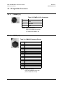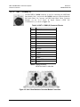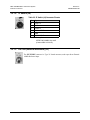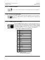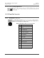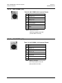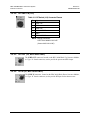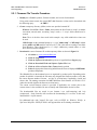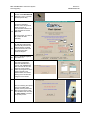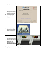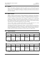
1
MBT-4000 Multi-Band Transceiver System Installation and Operation Manual IMPORTANT NOTE: The information contained in this document supersedes all previously published information regarding this product. Product specifications are subject to change without prior notice. Part Number MN/MBT4000.IOM Revision 4 MBT-4000 Multi-Band Transceiver System Installation and Operation Manual Part Number MN/MBT4000.IOM Revision 4 July 2, 2009 Copyright © 2009 Comtech EF Data. All rights reserved. Printed in the USA. Comtech EF Data, 2114 West 7th Street, Tempe, Arizona 85281 USA, 480.333.2200, FAX: 480.333.2161 This page is intentionally blank. ii Errata A for MN/MBT4000.IOM Rev 4 Comtech EF Data Documentation Update Subject: Errata Part Number: PLM CO Number: Comments: ER-MNMBT4000.EA4 Chapter 4, p. 4-2, Update Table 4-2, C-band frequency ER-MNMBT4000.EA4 (Errata documents are not subject to revision.) C-0024197 See attached page(s). The new information will be included in the next released revision of the manual. PLM C-0024197 MBT-4000 Multi-Band Transceiver System System Operating Parameters 4.4 Revision 4 MN/MBT4000.IOM Block Down Converter Module (BDC-4000) Operating Parameters The BDC-4000 translates a band-specific input frequency block (C-, X-, or Ku- or Ka-Band) from the LNA down to L-Band (950 to 2000 MHz). Table 4-2. BDC-4000 C-, X-, KU-, and Ka-Band Operating Parameters Band Frequency LO Frequency Inverting C-Band X-Band Ku-Band-W (Single module containing three LOs) Ka-Band 3625 – 4200 MHz 7250 – 7750 MHz 2300 MHz 6300 MHz No No 10.95 – 11.70 GHz 11.7 – 12.20 GHz 12.250 – 12.75 GHz 20.20 – 21.20 GHz 10.00 GHz 10.75 GHz 11.30 GHz No Notes: 1. No spectral inversion, selectable inversion for inverted Block Down Converter. 2. 10 dB gain adjustment. 4.5 Monitoring Operations via the LED Indicators The MBT-4000 Multi-Band Transceiver System features two Light-Emitting Diode (LED) indicators – one for each operational unit (module). Each LED provides the user with visual cues to the operational, online, and offline status of the sytem. Figure 4-1 illustrates the location of the LED Indicators. Located on the top of the MBT-4000’s Base Module under a pivoting protective plate, the LEDs may be viewed by loosening the thumbscrew that keeps the plate in place; the user can then swing the plate away to reveal the LED display window. Appendix B. FAULTS/EVENTS provides complete details for interpreting the LED Indicators. Figure 4-1. MBT-4000 Multi-Band RF Transceiver LED Indicators 4–2 Table of Contents TABLE OF CONTENTS .............................................................................................................. III TABLES ...................................................................................................................................... VI FIGURES .................................................................................................................................... VI PREFACE .................................................................................................................................. VII About this Manual .................................................................................................................................... vii New in this Release ................................................................................................................................. vii Reporting Comments or Suggestions Concerning this Manual .............................................................. vii Conventions and References ................................................................................................................... viii Cautions and Warnings .......................................................................................................................... viii Recommended Standard Designations................................................................................................... viii Trademarks ............................................................................................................................................ viii Metric Conversion ................................................................................................................................. viii Electromagnetic Compatibility (EMC) Compliance............................................................................... ix EN 55022 –1998 Compliance .................................................................................................................. ix EN 55082-1 – 1997 Compliance .............................................................................................................. ix Federal Communications Commission (FCC) ......................................................................................... ix Safety Compliance ...................................................................................................................................... x EN 60950 – 1997 Compliance .................................................................................................................. x Low Voltage Directive (LVD) .................................................................................................................. x Warranty Policy ......................................................................................................................................... xi Limitations of Warranty ........................................................................................................................... xi Exclusive Remedies ................................................................................................................................ xii Customer Support .................................................................................................................................... xiii Online Customer Support ...................................................................................................................... xiii CHAPTER 1. INTRODUCTION ............................................................................................. 1–1 1.1 Overview ...................................................................................................................................... 1–1 1.2 Functional Description ............................................................................................................... 1–1 1.3 Common Features ....................................................................................................................... 1–2 1.4 Options ......................................................................................................................................... 1–2 iii MBT-4000 Multi-Band Transceiver System Table of Contents 1.5 Revision 4 MN/MBT4000.IOM System Overview ......................................................................................................................... 1–3 1.6 Summary of Specifications ......................................................................................................... 1–4 1.6.1 Environmental & Physical .................................................................................................... 1–4 1.6.2 BUC-4000 Block Up Converter ODU .................................................................................. 1–4 1.6.3 BDC-4000 Block Down Converter ODU ............................................................................. 1–5 1.7 Dimensional Envelope ................................................................................................................ 1–6 CHAPTER 2. INSTALLATION .............................................................................................. 2–1 2.1 Unpacking and Inspection .......................................................................................................... 2–1 2.2 Installation ................................................................................................................................... 2–2 2.3 Operation ..................................................................................................................................... 2–2 CHAPTER 3. EXTERNAL CONNECTORS ........................................................................... 3–1 3.1 External Connectors Overview .................................................................................................. 3–1 3.2 MBT-4000 External Connectors ................................................................................................ 3–2 3.2.1 IF Signal Side Connectors..................................................................................................... 3–3 3.2.1.1 POWER (J1) ..................................................................................................................... 3–3 3.2.1.2 COMM (J2) ....................................................................................................................... 3–3 3.2.1.3 UNIT 1 COMM (J3) ......................................................................................................... 3–4 3.2.1.4 IF Switch (J4) .................................................................................................................... 3–5 3.2.1.5 Ext Ref (External Reference) (J5) .................................................................................... 3–5 3.2.1.6 UNIT 2 COMM (J6) ......................................................................................................... 3–6 3.2.1.7 Ground Connector ............................................................................................................. 3–7 3.2.1.8 IF IN (J4, BUC-4000 ONLY) ........................................................................................... 3–7 3.2.1.9 COMM (J6, BUC-/BDC-4000)......................................................................................... 3–7 3.2.1.10 IF OUT (J4, BDC-4000 ONLY) ................................................................................... 3–8 3.2.2 RF Signal Side Connectors ................................................................................................... 3–8 3.2.2.1 REDUNDANT LOOP (J7) ............................................................................................... 3–8 3.2.2.2 AUX COMM 2 (J8) .......................................................................................................... 3–9 3.2.2.3 AUX COMM 1 (J9) .......................................................................................................... 3–9 3.2.2.4 RF SWITCH (J10) .......................................................................................................... 3–10 3.2.2.5 RF OUT (J5, BUC-4000 ONLY) .................................................................................... 3–10 3.2.2.6 RF IN (J5, BDC-4000 ONLY) ........................................................................................ 3–10 CHAPTER 4. SYSTEM OPERATING PARAMETERS.......................................................... 4–1 4.1 Overview ...................................................................................................................................... 4–1 4.2 Remote Configuration, Monitoring and Control ..................................................................... 4–1 4.3 Block Up Converter Module (BUC-4000) Operating Parameters.......................................... 4–1 iv MBT-4000 Multi-Band Transceiver System Table of Contents Revision 4 MN/MBT4000.IOM 4.4 Block Down Converter Module (BDC-4000) Operating Parameters ..................................... 4–2 4.5 Monitoring Operations via the LED Indicators ....................................................................... 4–2 CHAPTER 5. FLASH UPGRADING ...................................................................................... 5–1 5.1 Overview ...................................................................................................................................... 5–1 5.2 Flash Upgrading via Internet ..................................................................................................... 5–1 5.2.1 Firmware File Transfer Procedure ........................................................................................ 5–2 5.3 Flash Upgrade Procedure ........................................................................................................... 5–3 APPENDIX A. REMOTE CONTROL .................................................................................... A–1 A.1 Overview ..................................................................................................................................... A–1 A.2 RS-485 ......................................................................................................................................... A–1 A.3 RS-232 ......................................................................................................................................... A–2 A.4 Basic Protocol ............................................................................................................................. A–2 A.5 Packet Structure......................................................................................................................... A–2 A.5.1 Start of Packet ...................................................................................................................... A–3 A.5.2 Target Address ..................................................................................................................... A–3 A.5.3 Address Delimiter ................................................................................................................ A–3 A.5.4 Instruction Code ................................................................................................................... A–3 A.5.5 Instruction Code Qualifier ................................................................................................... A–4 A.5.6 Optional Message Arguments .............................................................................................. A–5 A.5.7 End of Packet ....................................................................................................................... A–5 A.6 Remote Commands and Queries .............................................................................................. A–6 APPENDIX B. FAULTS/EVENTS ......................................................................................... B–1 B.1 LED Status Indicators ............................................................................................................... B–1 B.2 Faults/Events .............................................................................................................................. B–2 B.2.1 Summary Faults ................................................................................................................... B–2 B.2.2 Configurable Summary Faults ............................................................................................. B–3 B.2.3 Informational Events ............................................................................................................ B–4 APPENDIX C. REDUNDANCY CONFIGURATION / OPERATION ..................................... C–1 C.1 Overview ..................................................................................................................................... C–1 C.2 Single-Base Redundancy Operation ......................................................................................... C–1 v MBT-4000 Multi-Band Transceiver System Table of Contents Revision 4 MN/MBT4000.IOM C.3 Dual-Base (Chain) Redundancy Operation ............................................................................. C–2 C.4 External Fault Monitoring ........................................................................................................ C–3 C.5 LNA Power Supply Current Monitoring ................................................................................. C–3 C.6 Gain Equalization of Redundant Units .................................................................................... C–4 C.7 Operational Configuration Commands ................................................................................... C–4 Tables Table 3-1. MBT-4000 External Connectors ............................................................................................ 3–2 Table 3-2. POWER (J1) Pin Connections ................................................................................................. 3–3 Table 3-3. COMM (J2) Connector Pinouts ............................................................................................... 3–3 Table 3-4. UNIT 1 COMM (J3) Connector Pinouts ................................................................................. 3–4 Table 3-5. IF Switch (J4) Connector Pinouts ............................................................................................ 3–5 Table 3-6. UNIT 2 COMM (J6) Connector Pinouts ................................................................................. 3–6 Table 3-7. UNIT 2 COMM (J6) Connector Pinouts ................................................................................. 3–7 Table 3-8. REDUNDANT LOOP (J7) Connector Pinouts ....................................................................... 3–8 Table 3-9. AUX COMM 2 (J8) Connector Pinouts .................................................................................. 3–9 Table 3-10. AUX COMM 1 (J9) Connector Pinouts ................................................................................ 3–9 Table 3-11. RF Switch (J10) Connector Pinouts .................................................................................... 3–10 Table 4-1. BUC-4000 C-, X-, Ku-, and Ka-Band Operating Parameters ................................................. 4–1 Table 4-2. BDC-4000 C-, X-, KU-, and Ka-Band Operating Parameters................................................. 4–2 Table B-1. MBT-4000 Summary Faults .................................................................................................. B–2 Table B-2. BDC-4000/BUC-4000 Summary Faults ................................................................................ B–2 Table B-3. MBT-4000 Configurable Summary Faults ............................................................................ B–3 Table B-4. BDC-4000 Configurable Summary Faults............................................................................. B–4 Table B-5. MBT-4000 Informational Events ........................................................................................... B–4 Table B-6. BDC-4000/BUC-4000 Informational Events......................................................................... B–4 Figures Figure 1-1. Comtech EF Data MBT-4000 Multi-Band RF Transceiver ..................................................... 1–1 Figure 1-2. MBT-4000 Operational Schematic ........................................................................................ 1–2 Figure 1-3. Operational Diagram for Dual-Base (Chain) Redundancy Option ........................................ 1–3 Figure 1-4. MBT-4000 Dimensional Envelope ........................................................................................ 1–6 Figure 3-1. MBT-4000 External Connectors ............................................................................................ 3–1 Figure 3-2. Unit 1 Base Module to Converter Module Connection .......................................................... 3–4 Figure 3-3. Unit 2 Base Module to Converter Module Connection .......................................................... 3–6 Figure 4-1. MBT-4000 Multi-Band RF Transceiver LED Indicators ......................................................... 4–2 Figure 5-1. Flash Update via Internet ....................................................................................................... 5–1 Figure B-1. MBT-4000 LED Indicators .................................................................................................. B–1 Figure B-2. Faulted System Example ...................................................................................................... B–2 Figure C-1. Dual-Base (Chain) Redundancy Operation .......................................................................... C–2 vi PREFACE About this Manual This manual provides installation and operation information for the Comtech EF Data MBT-4000 Multi-Band Transceiver System. This is a technical document intended for earth station engineers, technicians, and operators responsible for the operation and maintenance of the MBT-4000. Comtech EF Data has reviewed this manual thoroughly in order to provide an easy-to-use guide to your equipment. All statements, technical information, and recommendations in this manual and in any guides or related documents are believed reliable, but the accuracy and completeness thereof are not guaranteed or warranted, and they are not intended to be, nor should they be understood to be, representations or warranties concerning the products described. Further, Comtech EF Data reserves the right to make changes in the specifications of the products described in this manual at any time without notice and without obligation to notify any person of such changes. If you have any questions regarding your equipment or the information in this manual, contact the Comtech EF Data Customer Support Department. New in this Release • This manual (CEFD P/N MN/MBT4000.IOM) has been revised in its entirety to comply with current Comtech EF Data Technical Publications standards and practices. • All Errata and/or Addenda content generated since publication of the previous revision (MN/MBT4000.IOM Rev 3, released June 3, 2005) has been incorporated into this revision. • The Flash Upgrade procedure outlined in Chapter 5 serves to supersede CEFD Application Note P/N AN/MBT4000 (released June 22, 2006) in its entirety. Reporting Comments or Suggestions Concerning this Manual Comments and suggestions regarding the content and design of this manual are appreciated. To submit comments, please contact the Comtech EF Data Technical Publications Department: [email protected]. vii MBT-4000 Multi-Band Transceiver System Preface Revision 4 MN/MBT4000.IOM Conventions and References Cautions and Warnings IMPORTANT or NOTE indicates information critical for proper equipment function. IMPORTANT CAUTION WARNING CAUTION indicates a hazardous situation that, if not avoided, may result in minor or moderate injury. CAUTION may also be used to indicate other unsafe practices or risks of property damage. WARNING indicates a potentially hazardous situation that, if not avoided, could result in death or serious injury. Recommended Standard Designations Recommended Standard (RS) Designations have been superseded by the new designation of the Electronic Industries Association (EIA). References to the old designations are shown only when depicting actual text displayed on the screen of the unit (RS-232, RS-485, etc.). All other references in the manual will be shown with the EIA designations. Trademarks Other product names mentioned in this manual may be trademarks or registered trademarks of their respective companies and are hereby acknowledged. Metric Conversion Metric conversion information is located on the inside back cover of this manual. This information is provided to assist the operator in cross-referencing non-metric to metric conversions. viii MBT-4000 Multi-Band Transceiver System Preface Revision 4 MN/MBT4000.IOM Electromagnetic Compatibility (EMC) Compliance This is a Class A product. In a domestic environment, it may cause radio interference that requires the user to take adequate protection measures. EN 55022 –1998 Compliance This equipment meets the radio disturbance characteristic specifications for information technology equipment as defined per EN 55022 1998. EN 55082-1 – 1997 Compliance This equipment meets the EMC/generic immunity standard as defined per EN 55082-1 1997. Federal Communications Commission (FCC) This equipment has been tested and found to comply with the limits for a Class A digital device, pursuant to Part 15 of the FCC rules. These limits are designed to provide reasonable protection against harmful interference when the equipment is operated in a commercial environment. This equipment generates, uses, and can radiate radio frequency energy. If not installed and used in accordance with the instruction manual, it may cause harmful interference to radio communications. Operation of this equipment in a residential area is likely to cause harmful interference; in which case, users are required to correct the interference at their own expense. NOTE To ensure compliance, properly shielded cables for DATA I/O shall be used. More specifically, these cables shall be shielded from end to end, ensuring a continuous shield. ix MBT-4000 Multi-Band Transceiver System Preface Revision 4 MN/MBT4000.IOM Safety Compliance EN 60950 – 1997 Compliance Applicable testing is routinely performed as a condition of manufacturing on all units to ensure compliance with safety requirements of the European Union Low Voltage Directive (EN 60950). This equipment meets the Safety of Information Technology Equipment specification as defined in EN 60950. Low Voltage Directive (LVD) The following information is applicable for EN 60950: <HAR> ! Type of power cord required for use in the European Union. CAUTION: Double-pole/Neutral Fusing ACHTUNG: Zweipolige bzw. Neutralleiter-Sicherung International Symbols: Symbol Definition Symbol Definition ~ Alternating Current Protective Earth / Safety Ground Fuse Chassis Ground For additional symbols, refer to Cautions and Warnings listed earlier in this Preface. NOTE x MBT-4000 Multi-Band Transceiver System Preface Revision 4 MN/MBT4000.IOM Warranty Policy Comtech EF Data products are warranted against defects in material and workmanship for a specific period from the date of shipment, and this period varies by product. In most cases, the warranty period is two years. During the warranty period, Comtech EF Data will, at its option, repair or replace products that prove to be defective. Repairs are warranted for the remainder of the original warranty or a 90 day extended warranty, whichever is longer. Contact Comtech EF Data for the warranty period specific to the product purchased. For equipment under warranty, the owner is responsible for freight to Comtech EF Data and all related customs, taxes, tariffs, insurance, etc. Comtech EF Data is responsible for the freight charges only for return of the equipment from the factory to the owner. Comtech EF Data will return the equipment by the same method (i.e., Air, Express, Surface) as the equipment was sent to Comtech EF Data. All equipment returned for warranty repair must have a valid RMA number issued prior to return and be marked clearly on the return packaging. Comtech EF Data strongly recommends all equipment be returned in its original packaging. Comtech EF Data Corporation’s obligations under this warranty are limited to repair or replacement of failed parts, and the return shipment to the buyer of the repaired or replaced parts. Limitations of Warranty The warranty does not apply to any part of a product that has been installed, altered, repaired, or misused in any way that, in the opinion of Comtech EF Data Corporation, would affect the reliability or detracts from the performance of any part of the product, or is damaged as the result of use in a way or with equipment that had not been previously approved by Comtech EF Data Corporation. The warranty does not apply to any product or parts thereof where the serial number or the serial number of any of its parts has been altered, defaced, or removed. The warranty does not cover damage or loss incurred in transportation of the product. The warranty does not cover replacement or repair necessitated by loss or damage from any cause beyond the control of Comtech EF Data Corporation, such as lightning or other natural and weather related events or wartime environments. The warranty does not cover any labor involved in the removal and or reinstallation of warranted equipment or parts on site, or any labor required to diagnose the necessity for repair or replacement. The warranty excludes any responsibility by Comtech EF Data Corporation for incidental or consequential damages arising from the use of the equipment or products, or for any inability to use them either separate from or in combination with any other equipment or products. xi MBT-4000 Multi-Band Transceiver System Preface Revision 4 MN/MBT4000.IOM A fixed charge established for each product will be imposed for all equipment returned for warranty repair where Comtech EF Data Corporation cannot identify the cause of the reported failure. Exclusive Remedies Comtech EF Data Corporation’s warranty, as stated is in lieu of all other warranties, expressed, implied, or statutory, including those of merchantability and fitness for a particular purpose. The buyer shall pass on to any purchaser, lessee, or other user of Comtech EF Data Corporation’s products, the aforementioned warranty, and shall indemnify and hold harmless Comtech EF Data Corporation from any claims or liability of such purchaser, lessee, or user based upon allegations that the buyer, its agents, or employees have made additional warranties or representations as to product preference or use. The remedies provided herein are the buyer’s sole and exclusive remedies. Comtech EF Data shall not be liable for any direct, indirect, special, incidental, or consequential damages, whether based on contract, tort, or any other legal theory. xii MBT-4000 Multi-Band Transceiver System Preface Revision 4 MN/MBT4000.IOM Customer Support Contact the Comtech EF Data Customer Support Department for: • Product support or training • Reporting comments or suggestions concerning manuals • Information on upgrading or returning a product A Customer Support representative may be reached at: Comtech EF Data Attention: Customer Support Department 2114 West 7th Street Tempe, Arizona 85281 USA 480.333.2200 (Main Comtech EF Data number) 480.333.4357 (Customer Support Desk) 480.333.2161 FAX To return a Comtech EF Data product (in-warranty and out-of-warranty) for repair or replacement: • Contact the Comtech EF Data Customer Support Department. Be prepared to supply the Customer Support representative with the model number, serial number, and a description of the problem. • Request a Return Material Authorization (RMA) number from the Comtech EF Data Customer Support representative. • Pack the product in its original shipping carton/packaging to ensure that the product is not damaged during shipping. • Ship the product back to Comtech EF Data. (Shipping charges should be prepaid.) Online Customer Support An RMA number request can be requested electronically by contacting the Customer Support Department through the online support page at www.comtechefdata.com/support.asp: • Click on “Service” for detailed instructions on our return procedures. • Click on the “RMA Request Form” hyperlink, then fill out the form completely before sending. • Send e-mail to the Customer Support Department at [email protected]. For information regarding this product’s warranty policy, refer to the Warranty Policy, p. xii. xiii MBT-4000 Multi-Band Transceiver System Preface Revision 4 MN/MBT4000.IOM Notes: xiv Chapter 1. INTRODUCTION 1.1 Overview Comtech EF Data’s MBT-4000 Multi-Band RF Transceiver, shown in Figure 1-1, is designed to perform C-, X-, or Ku-Band RF to L-Band down conversion and L-Band to C-, X-, or Ku- or KaBand RF up conversion. Figure 1-1. Comtech EF Data MBT-4000 Multi-Band RF Transceiver 1.2 Functional Description The MBT-4000 is designed to perform the following functions: • C-, X-, or Ku-Band RF to L-Band down conversion • L-Band to C-, X-, or Ku-Band RF up conversion • RF Band switching in minimal time without requiring tools • Easy expansion for providing a redundant system or other frequency bands • Automatic band identification for the Block Up converter (BUC), Block Down Converter (BDC), and antenna feed (if the feeds provide an identifying connector) 1–1 MBT-4000 Multi-Band Transceiver System Introduction Revision 4 MN/MBT4000.IOM • System status verification via LEDs located behind a removable cover • Flexible configuration: 2 Ups 2 Downs 1Up / 1 Down Figure 1-2 depicts the operation schematic for a typical MBT-4000 application. LBC-4000 From 70 MHz Modem IF In BUC-4000C RF Out Ref In L-Band 70 MHz IF Out RF In RF Out To C-Band HPA 5 MHz M&C To Modem IF In RS-485 L-Band 5 MHz RS-485 Ref In M&C LBC-4000 To Modem 70 MHz BDC-4000C L-Band IF Out IF Out RF In Ref In RS-485 M&C IF Out RF In From C-Band LNA 5 MHz 70 MHz To Modem RF IN L-Band L-Band Splitter Multi-Band Transceiver IDU Figure 1-2. MBT-4000 Operational Schematic 1.3 1.4 Common Features • Meets or exceeds MIL-STD-188-164A • Low phase noise • Auto band sensing capability • Functions in 1 MHz step sizes Options • Functions in 1 kHz step sizes • Dual-Base (Chain) Redundancy Operation (see Figure 1-3) 1–2 MBT-4000 Multi-Band Transceiver System Introduction Revision 4 MN/MBT4000.IOM Figure 1-3. Operational Diagram for Dual-Base (Chain) Redundancy Option 1.5 System Overview The MBT-4000 Multi-Band Tranceiver System is constructed in a modular configuration. Figure 1-4 illustrates the key components of this configuration. Common to the configuration for any frequency band of operation is a base module, which provides the Monitor and Control (M&C), Power Supply, and Reference function. Band-specific BUC and BDC modules can be mounted to the base module with clip-type fasteners. BUC and BDC modules for other bands and spares for all modules are stored in a transit case until needed. 1–3 MBT-4000 Multi-Band Transceiver System Introduction 1.6 Revision 4 MN/MBT4000.IOM Summary of Specifications 1.6.1 Environmental & Physical Dimensions (excluding connectors) See Figure 1-4 Operational Humidity – 122ºF (-40º to 50ºC) 14º – 122ºF (-10º to 50ºC) -58º – 160ºF (-50º to 71ºC) 5 – 95 non-condensing Operational Altitude 10,000 ft above sea level Prime Power 90 External Reference Input Either 5 MHz or 10 MHz ±5 dBm optional Temperature ODU: BUC-4000 Operating IDU: LBC-4000 Non-operating Frequency Stability 1.6.2 ODU: MBT-4000 -40º – 260 VAC, 47-63 Hz Over time -9 -7 1x10 /day, 1x10 /year Over temperature 40º – 55ºC, 1x10⁻⁸ BUC-4000 Block Up Converter ODU Input Frequency Range Output Frequency (by model) 950 – 2000 MHz BUC-4000C 5860 – 6650 MHz BUC-4000X 7900 – 8400 MHz BUC-4000Ku 13.75 – 14.50 GHz BUC-4000Ka 30.00 – 31.00 GHz 27.50 – 28.50 GHz (optional) 28.50 – 29.50 GHz (optional) 29.50 – 30.10 GHz (optional) Input/Output Impedance 50Ω Input Return Loss 15 dB minimum Output Return Loss 18 dB minimum Input Connector Type ‘N’ Female Output Connector Type ‘N’ Female (C-, X-, and Ku-Band) Gain 15 dB nominal at minimum attenuation (18 dB for Ku-Band BUC) User Attenuation Range 0 – 10 dB Output Power, P1dB +10 dBm minimum Third Order Intercept +20 dBm minimum Spurious Carrier Related -60 dBc Non-Carrier Related -60 dBm 1–4 MBT-4000 Multi-Band Transceiver System Introduction 1.6.3 Revision 4 MN/MBT4000.IOM BDC-4000 Block Down Converter ODU Output Frequency Range Input Frequency (by model) 950 – 2000 MHz BUC-4000C 3400 – 4200 MHz BUC-4000X 7250 – 7750 MHz BUC-4000Ku 10.95 – 12.75 GHz BUC-4000Ka 20.20 – 21.20 GHz 17.70 – 18.70 GHz (optional band) 18.70 – 19.20 GHz (optional band) 19.20 – 20.20 GHz (optional band) Input/Output Impedance 50Ω Input Return Loss 18 dB minimum Output Return Loss 15 dB minimum Input Connector Type ‘N’ Female (C-, X-, and Ku-Band) Output Connector Type ‘N’ Female Gain 15 dB nominal at minimum attenuation User Attenuation Range 0 – 10 dB, in 0.25 dB steps (0.1 dB optional) Output Power, P1dB +12 dBm minimum Third Order Intercept +22 dBm minimum Spurious (Carrier Related) -60 dBc Noise Figure 15 dB maximum @ 0 dB attenuation 1–5 MBT-4000 Multi-Band Transceiver System Introduction 1.7 Revision 4 MN/MBT4000.IOM Dimensional Envelope Figure 1-4. MBT-4000 Dimensional Envelope 1–6 Chapter 2. INSTALLATION 2.1 Unpacking and Inspection Inspect shipping containers for damage. If shipping containers are damaged, keep them until the contents of the shipment have been carefully inspected and checked for normal operation. The MBT-5003 L-Band Up/Down Converter System and its Installation and Operation Manual are packaged and shipped in a pre-formed, reusable cardboard carton containing foam spacing for maximum shipping protection. CAUTION Do not use any cutting tool that will extend more than 1” into the container and cause damage to the transceiver. Unpack and inspect the MBT-4000 as follows: Step Procedure 1 Cut the tape at the top of the carton indicated by OPEN THIS END. 2 Remove the cardboard/foam space covering the MBT-4000. 3 Remove the MBT-4000 and manual from the carton. 4 Save the packing material for storage or reshipment purposes. 5 Inspect the equipment for any possible damage incurred during shipment. 6 Check the equipment against the packing list to ensure the shipment is correct. 7 Refer to the next section (Section 2.2) for installation instructions. 2–1 MBT-4000 Multi-Band Transceiver System Installation 2.2 Revision 4 MN/MBT4000.IOM Installation The Base Module for the MBT-4000 system – which provides the M&C, Power Supply, and Reference interfaces – may be located near or on the antenna. Guide pins and mechanical clamps keep the bandspecific BUC and BDC modules in place on top of the Base Module. Cables to the antenna and IDU complete the installation. For complete information on the MBT-4000’s connectors, including the pinout tables, refer to Chapter 3. EXTERNAL CONNECTORS. To change the band of operation, the cables to the BUC/BDC modules are disconnected and the modules are unlatched from the Base unit, allowing removal and replacement of the existing modules with appropriate band-specific modules. 2.3 Operation Once all pertinent connections have been made between the MBT-4000 and other equipment, refer to Chapter 4. SYSTEM OPERATING PARAMETERS for further information. 2–2 Chapter 3. EXTERNAL CONNECTORS 3.1 External Connectors Overview As shown in Figure 3-1, connectors provided on the MBT4000 Multi-Band Transceiver System provide all necessary external connections between the the transceiver and other equipment. Note: This figure depicts an MBT-4000 configuration with (1) BUC-4000 Block Up Converter Module and (1) BDC-4000 Block Down Converter Module installed. RF Side IF Side (Cable Loops removed for clarity) Figure 3-1. MBT-4000 External Connectors 3–1 MBT-4000 Multi-Band Transceiver System External Connectors 3.2 Revision 4 MN/MBT4000.IOM MBT-4000 External Connectors Table 3-1 summarizes the external connections and identifies the chapter sections providing connector pinout information. Table 3-1. MBT-4000 External Connectors Signal Side (Sect.) Module MBT-4000 Base IF (3.2.1) Ref Des Name Sect. J1 POWER 3.2.1.1 J2 COMM 3.2.1.2 J3 UNIT 1 COMM 3.2.1.3 Serial communication and Summary Fault Communicate to BxC Unit 1 J4 IF SWITCH 3.2.1.4 Monitor & Control IF Switch Function AC Power J5 EXT REF 3.2.1.5 External 10 MHz Reference Input J6 UNIT 2 COMM 3.2.1.6 Communicate to BxC Unit 2 N/A N/A 3.2.1.7 #10-32 Ground stud J4 IF IN 3.2.1.8 IF Input J6 COMM 3.2.1.9 Communicate to Base Unit J4 IF OUT 3.2.1.10 IF Input J6 COMM 3.2.1.9 Communicate to Base Unit J7 REDUNDANT LOOP 3.2.2.1 Connected for dual base redundant operation J8 AUX COMM 2 3.2.2.2 J9 AUX COMM 1 3.2.2.3 J10 RF SWITCH 3.2.2.4 Monitor and Control RF Switch BUC-4000 J5 RF OUT 3.2.2.5 RF Output BDC-4000 J5 RF IN 3.2.2.6 RF Input BUC-4000 BDC-4000 MBT-4000 Base RF (3.2.2) 3–2 External Equipment Monitoring MBT-4000 Multi-Band Transceiver System External Connectors Revision 4 MN/MBT4000.IOM 3.2.1 IF Signal Side Connectors 3.2.1.1 POWER (J1) Table 3-2. POWER (J1) Pin Connections Pin Signal A LINE B NEUTRAL C GND NOTE - Mating Connectors: CEFD P/N CN/MS-STPG03F02 (ITT Cannon KPT06B-12-3S) 3.2.1.2 COMM (J2) Table 3-3. COMM (J2) Connector Pinouts Pin A B C D E F G H J K L M N P R S T U V Signal RS 485 Rx+ RS 485 RxRS 485 Tx+ RS 485 TxRS 232 RD NC RS 232 TD NC NC SUM FLT COMM SUM FLT NO SUM FLT NC NC NC NC NC GND GND NC NOTE - Mating Connectors: CEFD P/N CN/MS3116J14-19P (Cannon MS3116J14-19P) 3–3 MBT-4000 Multi-Band Transceiver System External Connectors 3.2.1.3 Revision 4 MN/MBT4000.IOM UNIT 1 COMM (J3) The J3 UNIT 1 COMM connector is used for connecting the MBT-4000 Base Module Unit 1 section to the J6 COMM connector featured on both the BUC-4000 Block Up Converter and BDC-4000 Block Down Converter Modules via the 15-15 Power & Signal Harness (CEFD P/N CA/WR10963-1), as shown in Figure 3-2. Table 3-4. UNIT 1 COMM (J3) Connector Pinouts Pin Signal A SUM FLT M RxD BXC C Tx+ BXC D GND E +7.5V F +7.5V G +15V H GND J Rx+ BXC K Rx- BXC L Tx- BXC B TxD BXC N SPARE P 10 MHz REF R SPARE NOTE – Mating Connector: CEFD P/N CN/8LT5-15B15PN Figure 3-2. Unit 1 Base Module to Converter Module Connection 3–4 MBT-4000 Multi-Band Transceiver System External Connectors 3.2.1.4 Revision 4 MN/MBT4000.IOM IF Switch (J4) Table 3-5. IF Switch (J4) Connector Pinouts Pin Signal A POS 1 IF B GND C POS 2 IF D POS 1 IND IF E GND F POS 2 IND IF NOTE - Mating Connectors: CEFD P/N CN/MS3116J10-6P (Cannon MS3116J10-6P) 3.2.1.5 Ext Ref (External Reference) (J5) The J5 EXT REF connector is a Type ‘N’ female connector, used to provide an External 10MHz Reference Input. 3–5 MBT-4000 Multi-Band Transceiver System External Connectors 3.2.1.6 Revision 4 MN/MBT4000.IOM UNIT 2 COMM (J6) The J6 UNIT 2 COMM connector is used for connecting the MBT-4000 Base Module Unit 2 section to the J6 COMM connector featured on both the BUC-4000 Block Up Converter and BDC-4000 Block Down Converter Modules, via the 15-15 Power & Signal Harness (CEFD P/N CA/WR10963-1), as shown in Figure 3-3. Table 3-6. UNIT 2 COMM (J6) Connector Pinouts Pin Signal A SUM FLT M RxD BXC C Tx+ BXC D GND E +7.5V F +7.5V G +15V H GND J Rx+ BXC K Rx- BXC L Tx- BXC B TxD BXC N SPARE P 10 MHz REF R SPARE NOTE – Mating Connector CEFD P/N CN/8LT5-15B15PN Figure 3-3. Unit 2 Base Module to Converter Module Connection 3–6 MBT-4000 Multi-Band Transceiver System External Connectors 3.2.1.7 Revision 4 MN/MBT4000.IOM Ground Connector A #10-32 stud is used for connecting a common chassis ground among equipment. 3.2.1.8 IF IN (J4, BUC-4000 ONLY) The J4 IF IN connector, located on the BUC-4000 Block Up Converter Module, is a Type ‘N’ female connector, used to provide the IF Input signal for the upconverter. 3.2.1.9 COMM (J6, BUC-/BDC-4000) The J6 COMM connector, featured on both the BUC-4000 Block Up Converter and BDC-4000 Block Down Converter Modules, is used for connecting the module to the MBT-4000 Base Module J3 UNIT 1 COMM or J6 UNIT 2 COMM connectors via the 15-15 Power & Signal Harness (CEFD P/N CA/WR10963-1), as shown in Figure 3-2 and Figure 3-3. Table 3-7. UNIT 2 COMM (J6) Connector Pinouts Pin Signal A SUM FLT B TxD BXC C Tx+ BXC D GND E +7.5V F +7.5V G +15V H GND J Rx+ BXC K Rx- BXC L Tx- BXC M RxD BXC N SPARE P 10 MHz REF R SPARE NOTE – Mating Connector: CEFD P/N CN/8LT5-15B15SN 3–7 MBT-4000 Multi-Band Transceiver System External Connectors Revision 4 MN/MBT4000.IOM 3.2.1.10 IF OUT (J4, BDC-4000 ONLY) The J4 IF OUT connector, located on the BDC-4000 Block Down Converter Module, is a Type ‘N’ female connector, used to provide the downcoverted IF Output signal. 3.2.2 RF Signal Side Connectors 3.2.2.1 REDUNDANT LOOP (J7) The J7 REDUNDANT LOOP connector is used to connect the MBT-4000 Base Module, via the Redundant Loop Bus Cable (CEFD P/N CA/WR11224), to another base unit for a dual base (redundant) setup. Table 3-8. REDUNDANT LOOP (J7) Connector Pinouts Pin Signal A SW POS 2 DRIVE OUT B GND C SW POS 2 DRIVE OUT D RF SW IND OUT E IF SW IND OUT F SW POS 1 DRIVE IN G SW POS 2 DRIVE IN H RF SW IND IN J IF SW IND IN K MBT A IND L MBT B IND M NC N BXC 1 FLT OUT P BXC 2 FLT OUT R BXC 1 FLT IN S BXC 2 FLT IN T NC U TX V RX 3–8 MBT-4000 Multi-Band Transceiver System External Connectors 3.2.2.2 Revision 4 MN/MBT4000.IOM AUX COMM 2 (J8) Table 3-9. AUX COMM 2 (J8) Connector Pinouts Pin Signal A AUX Rx + B B AUX Rx – B C AUX Tx + B D AUX Tx – B E +12.6V LNA B F I02 A/Fault G I02 B H GND NOTE - Mating Connectors: CEFD P/N CN/MS3116J12-8P (Cannon MS3116J12-8P) 3.2.2.3 AUX COMM 1 (J9) Table 3-10. AUX COMM 1 (J9) Connector Pinouts Pin Signal A AUX Rx + A B AUX Rx – A C AUX Tx + A D AUX Tx – A E +12.6V LNA A F IO1 A/Fault G IO1 B H GND NOTE - Mating Connectors: CEFD P/N CN/MS3116J12-8P (Cannon MS3116J12-8P) 3–9 MBT-4000 Multi-Band Transceiver System External Connectors 3.2.2.4 Revision 4 MN/MBT4000.IOM RF SWITCH (J10) Table 3-11. RF Switch (J10) Connector Pinouts Pin Signal A POS 1 RF B GND C POS 2 RF D POS 1 IND RF E GND F POS 2 IND RF NOTE – Mating Connectors: CEFD P/N CN/MS3116J10-6P (Cannon MS3116J10-6P) 3.2.2.5 RF OUT (J5, BUC-4000 ONLY) The J5 RF OUT connector, located on the BUC-4000 Block Up Converter Module, is a Type ‘N’ female connector, used to provide the upconverted RF Output. 3.2.2.6 RF IN (J5, BDC-4000 ONLY) The J5 RF IN connector, located on the BDC-4000 Block Down Converter Module, is a Type ‘N’ female connector, used to provide RF Input for the downcoverter. 3–10 Chapter 4. SYSTEM OPERATING PARAMETERS 4.1 Overview An introduction to the Monitoring and Control (M&C) features of the MBT-4000 Multi-Band RF Transceiver, as well as the operating parameters for the BUC-4000 Block Up Converter and BDC-4000 Block Down Converter, are provided in this chapter. 4.2 Remote Configuration, Monitoring and Control Remote monitoring and control (M&C) of the MBT-4000 is possible via use of a remotelyconnected PC or dumb terminal. From this location, the user may issue commands and queries to configure, control, and monitor one or more MBT-4000 systems. Complete information for these features is provided in Appendix A. REMOTE CONTROL. 4.3 Block Up Converter Module (BUC-4000) Operating Parameters The BUC-4000 translates the MBT-4000 L-Band output carrier to the desired output frequency (C, X-, or Ku- or Ka-Band) with an output level capable of driving a High-Power Amplifier (HPA). Table 4-1. BUC-4000 C-, X-, Ku-, and Ka-Band Operating Parameters Band Frequency LO Frequency Inverting C-Band 5850 – 6650 MHz 4900 MHz No X-Band 7900 – 8400 MHz 6950 MHz No Ku-Band-W 13.75 – 14.50 GHz 12.800 GHz No Ka-Band 30.00 – 31.00 GHz Notes: 1. No spectral inversion. 2. 10dB gain adjustment. 4–1 MBT-4000 Multi-Band Transceiver System System Operating Parameters 4.4 Revision 4 MN/MBT4000.IOM Block Down Converter Module (BDC-4000) Operating Parameters The BDC-4000 translates a band-specific input frequency block (C-, X-, or Ku- or Ka-Band) from the LNA down to L-Band (950 to 2000 MHz). Table 4-2. BDC-4000 C-, X-, KU-, and Ka-Band Operating Parameters Band Frequency LO Frequency Inverting C-Band 3400 – 4200 MHz 5150 MHz Yes X-Band 7250 – 7750 MHz 6300 MHz No Ku-Band-W (Single module containing three LOs) 10.95 – 11.70 GHz 11.7 – 12.20 GHz 12.250 – 12.75 GHz 10.00 GHz 10.75 GHz 11.30 GHz No Ka-Band 20.20 – 21.20 GHz Notes: 1. No spectral inversion, selectable inversion for inverted Block Down Converter. 2. 10 dB gain adjustment. 4.5 Monitoring Operations via the LED Indicators The MBT-4000 Multi-Band Transceiver System features two Light-Emitting Diode (LED) indicators – one for each operational unit (module). Each LED provides the user with visual cues to the operational, online, and offline status of the sytem. Figure 4-1 illustrates the location of the LED Indicators. Located on the top of the MBT-4000’s Base Module under a pivoting protective plate, the LEDs may be viewed by loosening the thumbscrew that keeps the plate in place; the user can then swing the plate away to reveal the LED display window. Appendix B. FAULTS/EVENTS provides complete details for interpreting the LED Indicators. Figure 4-1. MBT-4000 Multi-Band RF Transceiver LED Indicators 4–2 Chapter 5. FLASH UPGRADING 5.1 Overview This chapter provides procedural information for upgrading the firmware for the Base Module of the Comtech EF Data MBT-4000 Multi-Band Transceiver System. This is a technical document intended for users – i.e., earth station engineers, technicians, and operators – responsible for the operation and maintenance of the MBT-4000. This chapter also assumes that the user has familiarity with Microsoft Windows-based operating systems. 5.2 Flash Upgrading via Internet The MBT-4000 uses internal ‘Flash memory’ technology; this makes firmware upgrading very simple, and updates can now be sent via the Internet (Figure 5-1), via E-mail, or on CD. This chapter outlines the complete upgrading process as follows: • New firmware update for upgrading the MBT-4000 Base Unit is transferred to a userprovided PC intended for Monitor and Control (M&C) of the MBT-4000 system. • By simply connecting the MBT-4000 to an available serial port on the user-provided PC, the upgrade can then be performed without opening the MBT-4000 base unit. (Note: The block up and down converter modules are factory-serviced items, and are not updated during this procedure.) • Once the firmware update is extracted from the transferred archive file, the upgrade process is executed via use of a utility program, FLSHCSAT.exe. Figure 5-1. Flash Update via Internet 5–1 MBT-4000 Multi-Band Transceiver System Flash Upgrading Revision 4 MN/MBT4000.IOM 5.2.1 Firmware File Transfer Procedure 1. Identify the reflashable product, firmware number, and version for download. Using serial remote control, the current MBT-4000 firmware revision can be determined with the following query: <0/ FRW? 2. Create a temporary directory (folder) on the user-provided external PC. Windows: Select File > New > Folder, then rename the New Folder to "temp" or another convenient, unused name. Assuming "temp" works, a "c:\temp" folder should now be created. Note: The c: is the drive letter used in this example. Any valid writable drive letter can be used. CMD Prompt: At the command prompt (c:\>), type "mkdir temp” or “MD temp" without quotes (mkdir and MD stand for make directory). This is the same as creating a new folder from Windows. There should now be a "c:\temp" subdirectory created (where c: is the drive letter used in the example). 3. Download the correct firmware file to this temporary folder as shown in Figure 5-1: 1. Go online to: www.comtechefdata.com 2. Click on: Support tab 3. Click on: Software Downloads drop-down or hyperlink from Support page 4. Click on: Download Flash and Software Update Files icon 5. Click on: (Select a Product Line) Transceivers hyperlink 6. Select the appropriate firmware hyperlink from the roster of displayed MBT-4000 products/components. The flashable files on the download server are organized by product prefix. Depending on the product for which it is intended, the file name may designate the firmware number (verify that the correct firmware number is known – see Step 1); revision letter, if applicable; version; and release date. The naming convention for MBT-4000 Base Unit firmware is FW11811*.CCC (where the asterisk signifies the firmware revision letter). The current version firmware release is provided. If applicable, one version prior to the current release is also available. Be sure to identify and download the desired version. The downloadable files are stored in two formats: *.exe (self-extracting) and *.zip (compressed). Some firewalls will not allow the downloading of *.exe files. In this case, download the *.zip file instead. For additional help with "zipped" file types, refer to PKZIP for Windows, WinZip, or ZipCentral help files. PKZIP for DOS is not supported due to file naming conventions. 5–2 MBT-4000 Multi-Band Transceiver System Flash Upgrading Revision 4 MN/MBT4000.IOM 4. Extract the files to the temporary folder on the PC, then verify the success of the file extraction and transfer via the dir command. At least four files should be extracted: • ReleaseNotes_vX-X-X.pdf, where “X-X-X” denotes the firmware version. • FW11811x.CCC, where "x" denotes the firmware revision letter. • FLSHCSAT.EXE: CEFD Flash Upload Utility Program. • CCCflash.hlp: FLSHCSAT Help File. If these four files as identified are displayed, proceed to the next section to perform the flash upgrade. 5.3 Flash Upgrade Procedure Step Procedure Locate and Identify the MBT-4000 Multi-Band Transceiver System. 1 The illustration to the right serves to identify key features of a typical system. Ensure that the MBT-4000 system is connected to a user-provided, Windowsbased PC. 2 Note: If needed, the CA/WR12243-1 System Programming Cable is available from Comtech EF Data. Contact CEFD Customer Support for ordering information. 5–3 MBT-4000 Multi-Band Transceiver System Flash Upgrading 3 4 Revision 4 MN/MBT4000.IOM Double-click FLSHCSAT.EXE (filename or icon) to execute the flash upload utility. From the FLSHCSAT window, select the pertinent serial port used for communication between the user-provided PC and the MBT-4000. (In this example, as noted at ‘A’, COM1 has been selected.) A 5 Do not select a Baud Rate (noted at ‘B’) other than the default selection of 38400, unless otherwise instructed by Comtech EF Data Technical Support. 6 Click on ‘Software Upload’, as noted at ‘C’. 7 The user is prompted to select the firmware file to upload. Click ‘Choose File’, then select the file from the temporary folder created earlier by using the box to the right to navigate to the desired folder, then doubleclicking on the firmware file using the box to the left. 8 Prior to continuing the upload process, the MBT-4000 system must be powered off. Disconnect the power cable from the Base Unit, then click on ‘Start Upload’ to resume the upload process. B C 5–4 MBT-4000 Multi-Band Transceiver System Flash Upgrading 9 Revision 4 MN/MBT4000.IOM When prompted, reconnect the power cable to the Base Unit. Once communication has been established between the PC and MBT-4000, the upload will take place – do not interrupt this upload process. 10 Note: If the upload is not successful for any reason – e.g., the communications cable is not physically connected, the wrong COM port has been specified, the user inadvertently interrupted the upload, etc. – the user may troubleshoot the setup as needed, then click on ‘Repeat Upload’ or ‘Go Back to Start’ to resume/retry the upload process. 5–5 MBT-4000 Multi-Band Transceiver System Flash Upgrading 11 Upon successful completion of the upload, the user may click on ‘Go Back to Start’ (if, for example, more than one MBT-4000 system requires upgrade), or ‘Close’ (to exit the FLSHCSAT program). 12 If needed, disconnect the System Programming Cable (CEFD P/N CA/WR12243-1) and reconnect the original System Communications Connection Cable. 13 Revision 4 MN/MBT4000.IOM The LEDs on the MBT-4000 Base Unit will illuminate GREEN (unmuted) or YELLOW (muted) to indicate the current status of the Unit 1 and Unit 2 modules. (Note: If either LED illuminates RED, refer to Appendix B. FAULTS/EVENTS for further information.) The upgrade process has been successfully completed. 5–6 Appendix A. REMOTE CONTROL A.1 Overview This appendix describes the protocol and message command set for remote monitor and control of the MBT-4000 Multi-Band Transceiver System (more specifically, the BUC-4000 and BDC-4000 modules). The electrical interface is either an RS-485 multi-drop bus (for the control of many devices) or an RS-232 connection (for the control of a single device), and data is transmitted in asynchronous serial form using ASCII characters. Control and status information is transmitted in packets of variable length, in accordance with the structure and protocol defined in later sections. A.2 RS-485 For applications where multiple devices are to be monitored and controlled, a full-duplex (or 4wire plus ground) RS-485 is preferred. Half-duplex (2-wire plus ground) RS-485 is possible, but is not preferred. In full-duplex RS-485 communications, there are two separate, isolated, independent, differential-mode twisted pairs, each handling serial data in different directions. It is assumed that a 'Controller' device (a PC or dumb terminal) transmits data in a broadcast mode via one of the pairs. Many 'Target' devices are connected to this pair, and all simultaneously receive data from the Controller. The Controller is the only device with a line-driver connected to this pair – the Target devices have only line-receivers connected. In the other direction, on the other pair each Target has a tri-stateable line driver connected, and the Controller has a line-receiver connected. All the line drivers are held in high-impedance mode until one (and only one) Target transmits back to the Controller. Each Target has a unique address, and each time the Controller transmits, the address of the intended recipient Target is included in a framed 'packet' of data. All of the Targets receive the packet, but only one (the intended) will reply. The Target enables its output line driver and transmits its return data packet back to the Controller in the other direction, on the physically separate pair. RS-485 (full duplex) summary: • Two differential pairs – one pair for Controller-to-Target, one pair for Target-to-Controller. • Controller-to-Target pair has one line driver (Controller), and all Targets have line-receivers. • Target-to-Controller pair has one line receiver (Controller), and all Targets have tri-state drivers. A–1 MBT-4000 Multi-Band Transceiver System Remote Control A.3 Revision 4 MN/MBT4000.IOM RS-232 This is a much simpler configuration in which the Controller device is connected directly to the Target via a two-wire-plus-ground connection. Controller-to-Target data is carried, via RS-232 electrical levels, on one conductor, and Target-to-Controller data is carried in the other direction on the other conductor. A.4 Basic Protocol Whether in RS-232 or RS-485 mode, all data is transmitted as asynchronous serial characters, suitable for transmission and reception by a UART. The asynchronous character is fixed at 8-N-1 (8 data bits, no parity, one stop bit). Only two baud rates are supported: 9600 baud and 19200 baud. All data is transmitted in framed packets. The Controller is assumed a PC or ASCII dumb terminal that is in charge of the process of monitor and control. The Controller is the only device that is permitted to initiate, at will, the transmission of data. Targets are only permitted to transmit when they have been specifically instructed to do so by the Controller. All bytes within a packet are printable ASCII characters, less than ASCII code 127. In this context, the Carriage Return and Line Feed characters are considered printable. All messages from Controller-to-Target require a response – with one exception: This will be either to return data that has been requested by the Controller, or to acknowledge reception of an instruction to change the configuration of the Target. The exception to this is when the Controller broadcasts a message (such as Set Time/Date) using Address 0, when the Target is set to RS-485 mode. A.5 Packet Structure Controller-to-Target Start of Packet Target Address < ASCII code 60 (1 character) Address Delimiter Instruction Code / ASCII code 47 (4 or 6 characters) (1 character) Code Qualifier Optional Arguments = or ? ASCII codes 61 or 63 (3 characters) (1 character) End of Packet Carriage Return ASCII code 13 (n characters) (1 character) Optional Arguments End of Packet Example: <0412/MUT=1{CR} Target-to-Controller Start of Packet Target Address > ASCII code 62 (1 character) Address Delimiter Instruction Code / ASCII code 47 (4 or 6 characters) (1 character) Code Qualifier =, ?, !, or * ASCII codes 61,63,33 or 42 (3 characters) Example: >0412/MUT={CR}{LF} A–2 (1 character) (From 0 to n characters) Carriage Return, Line Feed ASCII codes 13,10 (2 characters) MBT-4000 Multi-Band Transceiver System Remote Control A.5.1 Revision 4 MN/MBT4000.IOM Start of Packet Controller-to-Target: This is the character '<' (ASCII code 60) Target-to-Controller: This is the character '>' (ASCII code 62) Because this is used to provide a reliable indication of the start of packet, these two characters may not appear anywhere else within the body of the message. A.5.2 Target Address Up to 9,999 devices can be uniquely addressed. In both RS-232 and RS-485 applications, the permissible range of values is 1 to 9999. It is programmed into a target unit using the remote control port. The BDC and BUC subdevices may also be addressed by appending the corresponding subdevice address. The subdevice address is ‘A1’ for the BUC and ‘A2’ for the BDC. For example, a mute command addressed to a BUC attached to an MBT-4000 at address 0412 will be: <0412A1/MUT=1{CR} The format of the response will be: >0412A1/MUT={CR}{LF} Subdevice addresses cannot be changed. IMPORTANT A.5.3 The Controller sends a packet with the address of a Target - the destination of the packet. When the Target responds, the address used is the same address, to indicate to the Controller the source of the packet. The Controller does not have its own address. Address Delimiter This is the ‘forward slash’ character '/' (ASCII code 47). A.5.4 Instruction Code This is a three-character alphabetic sequence that identifies the subject of the message. Wherever possible, the instruction codes have been chosen to have some significance. This aids in the readability of the message if seen in its raw ASCII form. Upper and lower case alphabetic characters (i.e., A-Z – ASCII codes 65-90, and a-z – ASCII codes 97-122) may be used. A–3 MBT-4000 Multi-Band Transceiver System Remote Control A.5.5 Revision 4 MN/MBT4000.IOM Instruction Code Qualifier This single character further qualifies the preceding instruction code. Code Qualifiers obey the following rules: 1. From Controller-to-Target, the only permitted values are: = (ASCII code 61) The = code is used as the assignment operator, and is used to indicate that the parameter defined by the preceding byte should be set to the value of the argument(s) that follow it. For example: MUT=1 would mean 'enable the Mute function.' ? (ASCII code 63) The ? (ASCII code 63) is used as the query operator, and is used to indicate that the Target should return the current value of the parameter defined by the preceding byte. For example: MUT? Would mean ‘return the current state of the Mute function.’ 2. From Target-to-Controller, the only permitted values are: = (ASCII code 61) The = code is used in two ways: First, if the Controller has sent a query code to a Target (for example: MUT? would mean ‘return the current state of the Mute function’), the Target would then respond with MUT=x, where ‘x’ represents the state in question (1 being ‘enabled’, 2 being ‘disabled). Second, if the Controller sends an instruction to set a parameter to a particular value, then, providing the value sent in the argument is valid, the Target will acknowledge the message by replying with MUT= (with no message arguments). ? (ASCII code 63) The ? code is only used as follows: If the Controller sends an instruction to set a parameter to a particular value, then, if the value sent in the argument is not valid, the Target will acknowledge the message by replying (for example) with MUT? (with no message arguments). This indicates that there was an error in the argument of the message sent by the Controller. ! (ASCII code 33) The ! code is only used as follows: If the Controller sends an instruction code that the Target does not recognize, the Target will acknowledge the message by echoing the invalid instruction, followed by the ! character; for example, XYZ! * (ASCII code 42) The * code is only used as follows: If the Controller sends an instruction to set a parameter to a particular value, then, if the value sent in the argument is valid, but the target is in the wrong mode (e.g., Standby mode in Redundancy configuration) such that it will not permit that particular parameter to be changed at that time, the Target will acknowledge the message by replying (for example) with MUT* (with no message arguments). # (ASCII code 35) The # code is only used as follows: If the controller sends an instruction code that the target cannot currently perform because of hardware resource issues, then the target will acknowledge the message by echoing the invalid instruction, followed by the # character; for example, MUT# (with no message arguments). A–4 MBT-4000 Multi-Band Transceiver System Remote Control A.5.6 Revision 4 MN/MBT4000.IOM Optional Message Arguments Arguments are not required for all messages. Arguments are ASCII codes for the characters 0 to 9 (ASCII codes 48-57), period (ASCII code 46), and comma (ASCII code 44). A.5.7 End of Packet Controller-to-Target: This is the 'Carriage Return' character (ASCII code 13). Target-to-Controller: This is the two-character sequence 'Carriage Return', 'Line Feed' (ASCII codes 13 and 10). Both indicate the valid termination of a packet. A–5 MBT-4000 Multi-Band Transceiver System Remote Control A.6 Revision 4 MN/MBT4000.IOM Remote Commands and Queries Where Column ‘C’ = Command; Column ‘Q’ = Query: Columns marked (X) indicate Command only, Query only, or Command/Query for Instruction Code. Instr Code C Q Page Instr Code C Q Page AFR X X A-7 RED X X A-18 ATT X X A-7 REF X X A-19 CAA X A-7 RET X A-19 CAI X A-7 RMS X A-20 CAS X A-8 RSN X A-21 CCS X A-9 RUS X A-21 X A-9 SBR X A-21 A-10 SFS X A-21 CID X CLC X X CMS X A-11 SPA X X A-21 CUS X A-12 SSA X X A-22 DAT X X A-12 SSW X EAM X X A-12 TIM X FRE X X A-12 FRW X LCM X A-22 TNA X A-22 A-12 TSC X A-23 X A-13 XRF X A-23 LCS X X A-13 LCW X X A-13, A-14 LFL X X A-14 X A-15 LNA MUT X X A-15 OFM X X A-24 ONL X A-15 RAI X A-16 X A-16 RAS X A-17 RCS X A-18 RAM X A-22 A–6 X MBT-4000 Multi-Band Transceiver System Remote Control Parameter Type Automatic Fault Recovery State Attenuation Revision 4 MN/MBT4000.IOM Command (Instruction Code and qualifier) AFR=x Valid on MBT, BDC, or BUC All Arguments Description of Arguments for Command (Note that all arguments are ASCII numeric codes – i.e., or Response ASCII codes between 48 and 57) to Query 1 byte, value Command or Query. of 0, 1 Enable Automatic Fault Recovery on a BXC, where: 0=Disabled 1=Enabled ATT=xx.xx BDC BUC 5 bytes, numeric Example: AFR=1 Command or Query. Valid attenuation level, in dB, at 0.25dB step size as factory default. Example: ATT=08.25 Clear All Stored Alarms CAA= All None Concise AUX COMM I/O N/A MBT n=Slot 1=AUX COMM 1 2=AUX COMM 2 Command only. Instructs the slave to clear all Stored Events. This command takes no arguments. Query only. Used to Query the Concise AUX COMM I/O of the MBT-4000 base unit, where: n=1 (AUX COMM 1) or 2 (AUX COMM 2) Example: <0001/CAI?n{cr} >0001?CAI=nabcd{cr}{lf} Where: n=1 or 2 (AUX COMM) a=12V (0=Off, 1=On) b=IOA (O=logic low [voltage input < 0.5], 1=logic high [voltage input > 2.7 vdc) c=IOB (O=logic low [voltage input < 0.5], 1=logic high [voltage input >2.7 vdc] d=Reserved (Always zero) A–7 Response to Query Command (Instruction (Target to Code and Controller) qualifier) AFR=(message OK) AFR? AFR? (received OK, but invalid arguments found) AFR*(message OK, but not permitted in current mode) ATT=(message OK) ATT? (received OK, but invalid arguments found) ATT*(message OK, but not permitted in current mode) ATT! (Command not accepted by MBT4000 base unit. It must be addressed to BUC or BDC subunits) CAA=(message OK) N/A Response to Query (Target to Controller) AFR=x (same format as command arguments) CAI=(message OK) CAI?n CAI? (received OK, but invalid arguments found) CAI*(message OK, but not permitted in current mode) CAI=nabcd (see description for details of arguments) N/A MBT-4000 Multi-Band Transceiver System Remote Control Command (Instruction Code and qualifier) Concise Alarm N/A Status Parameter Type Valid on MBT, BDC, or BUC All Revision 4 MN/MBT4000.IOM Arguments Description of Arguments for Command (Note that all arguments are ASCII numeric codes – i.e., or Response ASCII codes between 48 and 57) to Query 20 bytes, Query only. numeric Used to query the alarm status of the unit. Example: <0001/CAS?{cr} >0001/CAS=abcdefghijkl{cr}{lf} Where: a through l = 0 or 1, 0=OK, 1=FLT All: a=+15V Power Supply b=+7.5V Power Supply c=+5.0V Power Supply MBT-4000: d=+28V Power Supply e=Ref Oscillator Lock Detect f=Intermodule Communications g=Max current on LNA power supply AUX COMM1 h=Max current on LNA power supply AUX COMM2 i=Current window LNA power supply AUX COMM1 j=Current window LNA power supply AUX COMM2 k=Fault input AUX COMM1 (Pin F, J9) l=Fault input AUX COMM2 (Pin F, J8) BDC/BUC: d=X (reserved for future use) e=Synthesizer Lock Detect f=Heat-sink Temperature g=LNA current (BDC only, reserved on BUC) h=Reserved, always zero i-l=Not sent. A–8 Response to Command (Target to Controller) N/A Query (Instruction Code and qualifier) CAS? Response to Query (Target to Controller) CAS=x…X (see description for details of arguments) MBT-4000 Multi-Band Transceiver System Remote Control Parameter Type Concise Configuration Status Command (Instruction Code and qualifier) N/A Valid on MBT, BDC, or BUC All Arguments for Command or Response to Query 48 bytes (BDC) 41 bytes (BUC) 32 bytes (MBT) alphanumeric Revision 4 MN/MBT4000.IOM Response to Command (Target to Controller) Description of Arguments (Note that all arguments are ASCII numeric codes – i.e., ASCII codes between 48 and 57) Query only. Returns the summarized version of RCS. N/A Query (Instruction Code and qualifier) CCS? Example for MBT-04000 base unit: <0001/CCS?{cr} >0001/CCS=aa,bb,cc,dd,e,ff,g,h{cr}{lf} Response to Query (Target to Controller) CCS=x….x (see description for details of arguments) Where: aa=Frequency band for Unit 1 BXC (‘C”, ‘X”, ‘Ka’, ‘Ku’, or ‘NA’) bb=Frequency band for Unit 2 BXC (‘C’, ‘X’, ‘Ka’, ‘KU’, OR ‘NA’) cc=Direction for Unit 1 BXC (‘DN’=BDC, ‘UP’=BUC, ‘NA’=None) dd=Direction for Unit 2 BXC (‘DN’=BDC, ‘UP’=BUC, ‘NA’=None) e = X (reserved for future use) ff = X (reserved for future use) g = X (reserved for future use) h=External reference lock (1=locked, 0=Not locked) Example BDC or BUC: <0001A1/CCS?{cr}{lf} >0001A1/CCS=aaaaa,bb.bb,c,d.d,e,ff,g,hhhh,i,j,{CR}{lf} Circuit Identification CID= All 24 bytes, alphanumeric Where: aaaaa=Frequency in MHz bb.bb=Attenuation in dB c=mute state, 0=unmated, 1=muted d.d=slope adjust e=LNA current source (BDC only, BUC=X) ff=LNA current window (BDC only, BUC=XX) g=LNA fault logic (BDC only, BUC=X) hhhh=XXXX (reserved for future use) i=X (reserved for future use) j=Fault recovery, 0=Manual, 1=Auto Command or Query. Used to identify or name the unit or station. First line is limited to 24 characters. Example: CID={cr} -Earth Station 1----Converter #1--- A–9 CID=(message OK) CID? CID?(received OK, but invalid arguments found) CID=x…x (see description for details of arguments) MBT-4000 Multi-Band Transceiver System Remote Control Parameter Type Calibrate LNA Current Command (Instruction Code and qualifier) CLC= Valid on MBT, BDC, or BUC BDC Revision 4 MN/MBT4000.IOM Arguments Description of Arguments for Command (Note that all arguments are ASCII numeric codes – i.e., or Response ASCII codes between 48 and 57) to Query none Command only. This command is used to set the calibration point for the LNA current alarm feature. Example: CLC= Calibrate LNA Current CLC=s MBT S=1 byte Value of 1,2 1=LNA A 2= LNA 2 Command only. This command is used to set the calibration point for the LNA current alarm feature, where s = Source: 1=LNA A (AUX COMM1) 2=LNA B(AUX COMM2) Example: CLC=1 A–10 Response to Query Command (Instruction (Target to Code and Controller) qualifier) CLC=(message ok) N/A CLC?(received ok, but invalid arguments found) CLC*(message ok, but not permitted in current mode) CLC!(command not accepted by BDC sub-units.) CLC=(message ok) N/A CLC?(received ok, but invalid arguments found) CLC*(message ok, but not permitted in current mode) CLC!(command not accepted by BUC or BDC sub-units.) Response to Query (Target to Controller) N/A N/A MBT-4000 Multi-Band Transceiver System Remote Control Parameter Type Concise Maintenance Status Command (Instruction Code and qualifier) N/A Valid on MBT, BDC, or BUC All Revision 4 MN/MBT4000.IOM Arguments Description of Arguments for Command (Note that all arguments are ASCII numeric codes – i.e., or Response ASCII codes between 48 and 57) to Query 40 bytes Query only. alphanumeric Used to query the maintenance status of the unit in concise format. Response is comma delimited as follows: Example: <0001/CMS?{cr} >0001/CMS=aaa.a,bbb.b,ccc.c,ddd.d,eee.e,fff.f,ggg.g,h,I,j,k{cr} {lf} All: aaa.a=+15V power supply bbb.b=+7.5V power supply ccc.=+5V power supply MBT-4000 Base Unit: ddd.d=+28V power supply eee.e=Ref oscillator tuning voltage fff.f= XXX.X (reserved for future use) ggg.g= LNA current in mA for LNA B (AUX COMM2) h=local RF switch position (A, B, or N) i=Local IF switch position (A, B, or N) j=Remote RF switch position (A or B) k=Remote IF switch position (A or B) Notes: 1. It is not possible to detect the absence of a remote switch. 2. N= Not present. BDC: ddd.d=XXX.X (reserved for future use) eee.e=Synthesizer tuning voltage fff.f=LNA current in mA. ggg.g= Unit temperature in °C. h – k= Not present BUC: ddd.d=XXX.X (reserved for future use) eee.e=Synthesizer tuning voltage fff.f=RF output power in dBm (reserved) ggg.g=Unit temperature in °C h – k= Not present A–11 Response to Command (Target to Controller) N/A Query (Instruction Code and qualifier) CMS? Response to Query (Target to Controller) CMS=… (see description for details of arguments) MBT-4000 Multi-Band Transceiver System Remote Control Parameter Type Concise Utility Status Command (Instruction Code and qualifier) N/A Valid on MBT, BDC, or BUC MBT Arguments Description of Arguments for Command (Note that all arguments are ASCII numeric codes – i.e., or Response ASCII codes between 48 and 57) to Query 21 bytes Query only. alphanumeric Used to query the utility status of the MBT-400 Base Unit, response is comma delimited, where: aaaa=Physical Address bbbb=Remote Baud Rate Set RTC (Real-TimeClock) Date DAT=mmddyy All 6 bytes, numeric Enable Aux Com Fault Input Monitoring EAM=nm MBT n=1 AUX COMM1 2=AUX COMM2 m=0 (disabled), 1 (monitoring enabled) Operating RF Frequency FRE=xxxxx.xxx BDC BUC Revision 4 MN/MBT4000.IOM 9 bytes, numeric Example: <0001/CUS? >0001/CUS=aaaa,bbbb{cr}{lf} Command or Query. A command in the form mmddyy, where; dd = day of the month, between 01 and 31 mm = month of the year, between 01 and 12 yy = year, between 00 and 96 (2000 to 2096) Example: DAT=042503 would be April 24, 2003. Command or Query. EAM controls monitoring of external fault logic inputs to Aux Comm connectors (J8/J9 pin F). If enabled and external fault input is at Logic 1 ( > 2.6 vdc) a fault will be reported. Example: EAM=21 Command or Query Valid Operating RF frequency, in MHz. Example: FRE=11300.000 N/A All N/A Query (Instruction Code and qualifier) CUS? DAT= (message OK) DAT? DAT? (received OK, but invalid arguments found) DAT* (message OK, but not permitted in current mode) EAM=(message OK) EAM?n EAM?(received OK, but invalid arguments found) Response to Query (Target to Controller) CUS=x…x (see description for details of arguments) DAT=mmddyy (same format as command arguments) EAM=nm (same format as command arguments) Note: The inputs may be driven by a contact closure relay. They have an internal pull-up resistor (4.7k) to +5 vdc. For Ku BDCs: FRE values: 10950-11700 MHz an LO of 10000 MHz is activated FRE values: 11701-12250 MHz an LO of 10700 MHz is activated FRE values: 12251-12750 MHz an LO of 11300 MHz is activated Retreive Firmware Number Response to Command (Target to Controller) Query only Gets the Firmware Number of the unit. Example: FRW=FW12001’cr’’lf’ A–12 FRE=(message OK) FRE? FRE? (received OK, but invalid arguments found) FRE* (message OK, but not permitted in current mode) FRE! (command not accepted by MBT4000 base unit. It must be addressed to BUC or BDC subunits) N/A FRW? FRE=xxxxx.xxx (see description of arguments) FRW=FWxxxxx MBT-4000 Multi-Band Transceiver System Remote Control Parameter Type Monitor LNA Current LNA Current Source Command (Instruction Code and qualifier) N/A LCS=sx Valid on MBT, BDC, or BUC MBT MBT Arguments for Command or Response to Query s_xxx.x, s=1 byte, value of 1, 2 1=LNA A 2=LNA B xxx.x=5 bytes, numeric s=1 byte, value of 1, 2 1=LNA A 2=LNA B x=1 byte, value of 0, 1 0 = Disable 1 = Enable LNA Current Source LCS=x BDC x=1 byte, value of 0, 1 0 = Disable 1 = Enable Revision 4 MN/MBT4000.IOM Description of Arguments (Note that all arguments are ASCII numeric codes – i.e., ASCII codes between 48 and 57) Query only. Returns LNA Current Source Level in mA. Example: <0001/LCM?2 >0001/LCM=2_045.3{cr}{lf} Command or Query. LNA Current Source Enable, where: Source Enable 1=LNA A (Aux Comm 1) 0 = Disabled2=LNA B 2=LNB B (Aux Comm 2) 1 = Enabled Example: LCS=10 Command or Query. LNA Current Source Enable, where: 0 = Disabled 1 = Enabled Example: LCS=0 LNA Current Window LCW=xx BDC xx=2 bytes, numeric Command or Query. This command allows the user to set the alarm window in ± % of the calibrated LNA Current. Valid inputs are 20 to 50 in increments of 1%. In addition, setting the value to 99 disables the alarm function. Default is Disabled. Example: LCW=30, set alarm window for LNA A (Aux Comm 1) to ± 30%. A–13 Response to Query Command (Instruction (Target to Code and Controller) qualifier) LCM= (message ok) LCM?s LCM? (received ok, but invalid arguments s=1 byte, found) value of 1, 2 LCM! (command not accepted by BUC or BDC sub-units) Response to Query (Target to Controller) LCM=s_xxx.x LCS= (message ok) LCS? (received ok, but invalid arguments found) LCS* (message ok, but not permitted in current mode) LCS! (command not accepted by BUC or BDC sub-units) LCS= (message ok) LCS? (received ok, but invalid arguments found) LCS* (message ok, but not permitted in current mode) LCS! (command not accepted by BUC sub-units) LCW= (message ok) LCW? (received ok, but invalid arguments found) LCW* (message ok, but not permitted in current mode) LCW! (command not accepted by BDC sub-units) LCS?s LCS=sx s=1 byte, value of 1, 2 (same format as command arguments) LCS? LCS=x (same format as command arguments) LCW? LCW=xx (same format as command arguments) MBT-4000 Multi-Band Transceiver System Remote Control Parameter Type LNA Current Window Command (Instruction Code and qualifier) LCW=sxx Valid on MBT, BDC, or BUC MBT Arguments for Command or Response to Query s=1 byte, value of 1, 2 1=LNA A 2=LNA B xx=2 bytes, numeric LNA Fault Logic LFL=sx MBT s=1 byte, value of 1, 2 1=LNA A 2=LNA B x=1 byte, Value of 0, 1 0 = Disable 1 = Enable LNA Fault Logic LFL=x BDC x=1 byte, Value of 0, 1 0 = Disable 1 = Enable Revision 4 MN/MBT4000.IOM Description of Arguments (Note that all arguments are ASCII numeric codes – i.e., ASCII codes between 48 and 57) Command or Query. This command allows the user to set the alarm window in ± % of the calibrated LNA Current. Valid inputs are 20 to 50 in increments of 1%. In addition, setting the value to 99 disables the alarm function. Default is Disabled. Example: LCW=130, set alarm window for LNA A (Aux Comm 1) to ± 30%. Command or Query. Allows LNA Fault Logic to contribute to the summary fault relay, where: s = Source: 1=LNA A (Aux Comm 1) 2=LNA B (Aux Comm 2) x = Enable: 0 = Disabled 1 = Enabled Example: LFL=11 Command or Query. Allows LNA Fault Logic to contribute to the summary fault relay as follows: Enable 0 = Disabled 1 = Enabled Example: LFL=1 A–14 Response to Query Command (Instruction (Target to Code and Controller) qualifier) LCW= (message ok) LCW?s LCW? (received ok, but invalid arguments found) LCW* (message ok, but not permitted in current mode) LCW! (command not accepted by BUC or BDC sub-units) Response to Query (Target to Controller) LCW=sxx LFL= (message ok) LFL?s LFL? (received ok, but invalid arguments s=1 byte, found) Value of 1, 2 LCS* (message ok, but not permitted in current mode) LFL! (command not accepted by BUC or BDC sub-units) LFL=sx LFL= (message ok) LFL? LFL? (received ok, but invalid arguments found) LCS* (message ok, but not permitted in current mode) LFL! (command not accepted by BDC sub-units) LFL=x (same format as command arguments) (same format as command arguments) (same format as command arguments) MBT-4000 Multi-Band Transceiver System Remote Control Parameter Type Retrieve next 5 unread Stored Alarms Command (Instruction Code and qualifier) N/A Valid on MBT, BDC, or BUC All Revision 4 MN/MBT4000.IOM Arguments Description of Arguments for Command (Note that all arguments are ASCII numeric codes – i.e., or Response ASCII codes between 48 and 57) to Query 145 bytes Query only. The unit returns the oldest 5 Stored Events which have not yet been read over the remote control. Reply format: Sub-body{CR}Sub-body{CR}Sub-body{CR}Sub-body{CR}Subbody, where Sub-body=YYYYYYYYYY ZZ hhmmss mmddyy: YYYYYYYYYY=being the fault description. ZZ= being the alarm type. FT = Fault OK = Clear IF = Information Response to Command (Target to Controller) N/A Query (Instruction Code and qualifier) LNA? Response to Query (Target to Controller) LNA=YY..ss (see description for details of arguments) If there are no new events, the unit will reply with LNA* Mute State MUT=x BDC BUC 1 byte, value of 0,1 Note: See Appendix B for a description of possible Alarm/Events that may be found in the Alarm queue. Command or Query. Mute the unit, where: 0 = Disabled, 1 = Enabled Example: MUT=1 Online Status N/A MBT N/A Query only. Used to query the online status of the unit (useful in redundant configurations). Return position of corresponding RF switch. Example: <0001/ONL?{cr} >0001/ONL={cr}{lf} ON1=ON ,{cr} ON2=ON , {cr}{lf} A–15 MUT= (message OK) MUT? MUT? (received OK, but invalid arguments found) MUT* (message OK, but not permitted in current mode) MUT! (command not accepted by MBT4000 base unit. It must be addressed to BUC or BDC subunits) MUT=x (same format as command arguments) ONL= (message OK) ONL? ONL? (received OK, but invalid arguments found) ONL=x MBT-4000 Multi-Band Transceiver System Remote Control Parameter Type Retrieve AUX COMM I/O Redundancy Mode Command (Instruction Code and qualifier) N/A RAM=um Valid on MBT, BDC, or BUC MBT MBT Revision 4 MN/MBT4000.IOM Arguments for Command or Response to Query 1 byte, value of n=1 or 2 1=Aux Comm1 2=Aux Comm2 Query only. Used to Retrieve AUX COMM I/O of the MBT-4000 base unit, where: n=1 (Aux Comm 1) or 2 (Aux Comm 2). u=1 byte, value of 1, 2 1=Unit 1 2=Unit 2 Note: 0 = Logic low or input voltage < 0.5 vdc. 1 = Logic level 1 or input voltage > 2.7 vdc. Command or Query. Sets redundancy mode as follows: Unit: 1=Unit 1 2=Unit 2 Mode: 0 = Manual 1 = Automatic m=1 byte, Value of 0, 1 0 = Manual 1 = Automatic Description of Arguments (Note that all arguments are ASCII numeric codes – i.e., ASCII codes between 48 and 57) Example: <0001/RAI?1 Returns: >0001/RAI= 12V1=On IO1A=0 IO1B=1 RSVD=0 Example: RAM=11 A–16 Response to Query Command (Instruction (Target to Code and Controller) qualifier) RAI = (message OK) RAI?n RAI? (received OK, but invalid arguments found) RAI* (message OK, but not permitted in current mode) Response to Query (Target to Controller) RAI=x….x (see description for details of arguments) RAM= (message OK) RAM?u RAM? (received OK, but invalid arguments u=1 byte, found) Value of 1, 2 RAM* (message OK, but not permitted in current mode) RAM=um (same format as command arguments) MBT-4000 Multi-Band Transceiver System Remote Control Parameter Type Retrieve Alarm Status Command (Instruction Code and qualifier) N/A Valid on MBT, BDC, or BUC All Revision 4 MN/MBT4000.IOM Arguments Description of Arguments for Command (Note that all arguments are ASCII numeric codes – i.e., or Response ASCII codes between 48 and 57) to Query 92 bytes MBT- Query only. 4000 Used to Query the Alarm status of the unit 64 bytes Example for MBT-4000 base: (BUC), 74 bytes <0001/RAS?{cr} (BDC), >0001/RAS={cr} alphanumeric 15VT1=OK{cr} 7V5T1=OK{cr} 5VLT1=OK{cr} 28VT1=OK{cr} REFLD=OK{cr} IICST=OK{cr} LNAC1=OK{cr} LNAC2=OK{cr} LNAW1=OK{cr} LNAW2=OK{cr} LNAI1=OK{cr} LNAI2=OK{cr}{lf} Example for BDC or BUC: <0001A1/RAS?{cr} >0001A1/RAS={cr} 15VLT=OK{cr} 7V5LT=OK{cr} 5VOLT=OK{cr} REFLD=XX {cr} (reserved for future use) SYNLD=OK{cr} HSTMP=OK{cr} LNACR=OK{cr}{lf} Note: LNACR will only appear for BDC. A–17 Response to Command (Target to Controller) N/A Query (Instruction Code and qualifier) RAS? Response to Query (Target to Controller) RAS=x….x (see description for details of arguments) MBT-4000 Multi-Band Transceiver System Remote Control Parameter Type Retrieve Configuration Status Command (Instruction Code and qualifier) N/A Valid on MBT, BDC, or BUC All Revision 4 MN/MBT4000.IOM Arguments Description of Arguments for Command (Note that all arguments are ASCII numeric codes – i.e., or Response ASCII codes between 48 and 57) to Query 65 bytes Query only. (MBT-4000) Used to Query the configuration status of the unit 98 bytes Example for MBT-4000 base: (BDC), 76 bytes <0001/RCS?{cr} (BUC) >0001/RCS={cr} alphanumeric BF1=X {cr} BF2=X {cr} BT1=DN{cr} BT2=UP{cr} RED=0{cr} RAM=00{cr} MBT=N, A, or B EXT=0{cr}{lf} Response to Command (Target to Controller) N/A Query (Instruction Code and qualifier) RCS? Response to Query (Target to Controller) RCS=x….x (see description for details of arguments) Example for BDC or BUC: <0001A1/RCS?{cr} >0001A1/RCS={cr} FLO=06300{cr} ATT=01.00{cr} MUT=1{cr} SLP=0.3{cr} LCS=0{cr} LCW=99{cr} LFL=1{cr} REF=XXXX{cr} (reserved for future use) XRE=X{cr} (reserved for future use) AFR=0{cr}{lf} Redundancy State RED=x MBT 1 byte, value of 0,1, or 2 Note: For BUC, LCS, LCW, & LFL will not be shown. Command or Query. Controls redundancy state, where: 0=Off 1=Enables redundancy using single base unit 2=Enables redundancy using dual base units Example: RED=1 A–18 RED= (message OK) RED? RED? (received OK, but invalid arguments found) RED* (message OK, but not permitted in current mode) RED=x (same format as command arguments) MBT-4000 Multi-Band Transceiver System Remote Control Parameter Type Reference Oscillator Adjust Command (Instruction Code and qualifier) REF=xxxx Valid on MBT, BDC, or BUC MBT Revision 4 MN/MBT4000.IOM Arguments Description of Arguments for Command (Note that all arguments are ASCII numeric codes – i.e., or Response ASCII codes between 48 and 57) to Query 4 bytes, Command or Query. numeric Ref Osc Adjust, between 0000 and 0255. Resolution 0001. Example: REF=0197 Retrieve Equipment Type N/A All 22 bytes, alphanumeric Note: REF cannot be adjusted when the unit is locked to an external reference source. Query only. The unit returns a string indicated the Model Number and the software version installed Example: RET=BUC-4000 VER:1.0.3 A–19 Response to Query Command (Instruction (Target to Code and Controller) qualifier) REF= (message OK) REF? REF? (received OK, but invalid arguments found) REF* (message OK, but not permitted in current mode) Response to Query (Target to Controller) REF=xxxx (same format as command arguments) N/A RET=x….x (see description for details of arguments) RET? MBT-4000 Multi-Band Transceiver System Remote Control Parameter Type Retrieve Maintenance Status Command (Instruction Code and qualifier) N/A Valid on MBT, BDC, or BUC All Revision 4 MN/MBT4000.IOM Arguments Description of Arguments for Command (Note that all arguments are ASCII numeric codes – i.e., or Response ASCII codes between 48 and 57) to Query MBT-4000 Query only. 103 bytes, Used to Query the maintenance status of the unit. alphanumeric Example for MBT-4000 base: BDC – <0001/RMS?{cr} 98 bytes, >0001/RMS={cr}{lf} alphanumeric 15VT1=015.1{cr} 7V5T1=007.7{cr} BUC – 5VLT1=005.0{cr} 98 bytes, 28VT1=027.2{cr} alphanumeric REFVT=001.3{cr} LNA_1=000.0{cr} LNA_2=000.0{cr} RFSWP=B{cr} IFSWP=N{cr} RRFSW=B{cr} RIFSW=B{cr}{lf} Example for BUC: <0001A2/RMS={cr} >0001A2/RMS={cr}{lf} 15VT=015.1{cr} 7V5T=007.6{cr} 5VLT=005.2{cr} REFV=XXX.X{cr} (reserved for future use) SYNT=007.2{cr} POUT=XXX.X{cr} (reserved for future use) TEMP=+25.0{cr}{lf} Example for BDC: <0001A1/RMS={cr} >0001A1/RMS={cr}{lf} 15VT=015.1{cr} 7V5T=007.6{cr} 5VLT=005.2{cr} REFV=XXX.X{cr} (reserved for future use) SYNT=007.2{cr} LNAC=255.0{cr} TEMP=+25.0{cr}{lf} Note: “REFV” will show tuning voltage of reference OSC for standalone. Otherwise REFV=xxx.x which means Not Applicable. A–20 Response to Command (Target to Controller) N/A Query (Instruction Code and qualifier) RMS? Response to Query (Target to Controller) RMS=x….x (see description for details of arguments) MBT-4000 Multi-Band Transceiver System Remote Control Command (Instruction Code and qualifier) Serial Number N/A Valid on MBT, BDC, or BUC All Retrieve Utility Status MBT Parameter Type N/A Revision 4 MN/MBT4000.IOM Arguments Description of Arguments for Command (Note that all arguments are ASCII numeric codes – i.e., or Response ASCII codes between 48 and 57) to Query 9 bytes, Query only. numeric Used to Query the units 9 digit serial number. 000000000 to Slave returns its S/N, in the form xxxxxxxxx. 999999999 Example: RSN=000000165 24 bytes Query only. alphanumeric Used to Query the utility status of the MBT-4000 base unit.. Response to Command (Target to Controller) N/A Query (Instruction Code and qualifier) RSN? Response to Query (Target to Controller) RSN= x….x (see description for details of arguments) N/A RUS? RUS=x….x (see description for details of arguments) SBR= (message OK) SBR? SBR? (received OK, but invalid arguments found) SBR! (Command not accepted by BUC and BDC sub-units.) N/A SFS? SBR=xxxx (same format as command arguments) Example: <0001/RUS={cr} >0001/RUS={cr}{lf} ADR=0001{cr} BDR=9600{cr}{lf} Remote Baud Rate SBR=xxxx MBT 4 bytes, Command or Query. Set remote baud rate as follows: 9600 = 9600 baud 19K2 = 19200 baud Summary Fault Status N/A All N/A Query only. Used to Query the status of the Summary Fault Relay, where: 0=OK 1=FT Remote Address SPA=xxxx MBT 4 byte, numeric Example: SFS? Command or Query. Set Physical Address-between 0001 to 9999. Resolution 0001 Example: SPA=0412 A–21 SPA= (message OK) SPA? SPA? (received OK, but invalid arguments found) SPA! (Command not accepted by BUC and BDC sub-units.) SFS=x (see description for details of arguments) SPA=xxxx (same format as command arguments) MBT-4000 Multi-Band Transceiver System Remote Control Parameter Type Slope Adjust Command (Instruction Code and qualifier) SSA=x.x Valid on MBT, BDC, or BUC BDC BUC Revision 4 MN/MBT4000.IOM Arguments Description of Arguments for Command (Note that all arguments are ASCII numeric codes – i.e., or Response ASCII codes between 48 and 57) to Query 3 bytes, Command or Query. numeric Slope adjust level, valid from 0.0 to 1.0 with 0.1 resolution. Example: SSA=0.3 Set Redundancy Switch SSW=xy MBT 2 bytes Command only. SSW control the switches dedicated to Slot1 or 2, and sets them to either Port A or Port B. Response to Query Command (Instruction (Target to Code and Controller) qualifier) SSA= (message OK) SSA? SSA? (received OK, but invalid arguments found) SSA* (message OK, but not permitted in current mode) SSA! (command not accepted by MBT4000 base unit. It must be addressed to BUC or BDC subunits) Response to Query (Target to Controller) SSA=x.x (same format as command arguments) SSW=(message OK) SSW=xy N/A N/A Syntax: SSW=xy, where: x = 1 or 2 depicting Slot 1 or 2 y = A or B depicting the switch direction. Direction A Switched to Converter on MBT_A B Switched to Converter on MBT_B Set RTC Time Retrieve Number of unread Stored Alarms TIM=hhmmss N/A All All 6 bytes, numeric 2 bytes, numeric Command or Query. A command in the form hhmmss, indicating the time from midnight, where: hh = hours, between 00 and 23 mm = minutes, between 00 and 59 ss = seconds, between 00 and 59 Example: TIM=231259 would be 23 hours, 12 minutes and 59 seconds from midnight. Query only. Returns the number of Stored Events which remain unread, in the form xx. Example reply: TNA=18 A–22 TIM = (message OK) TIM? TIM? (received OK, but invalid arguments found) TIM * (message OK, but not permitted in current mode) TIM=hhmmss (same format as command arguments) N/A TNA=xx (see description for details of arguments) TNA? MBT-4000 Multi-Band Transceiver System Remote Control Parameter Type Terminal Status change External Reference Fault Logic Revision 4 MN/MBT4000.IOM Command (Instruction Code and qualifier) N/A Valid on MBT, BDC, or BUC All Arguments Description of Arguments for Command (Note that all arguments are ASCII numeric codes – i.e., or Response ASCII codes between 48 and 57) to Query 1 byte, Query only. value of 0,1 Used to Query the status of the Terminal Status. Where: 0=no change in status 1=change in status XRF=x MBT 1 byte, value of 0,1 Example: TSC=0 Command or Query. XRF controls whether or not the Software monitors the external reference source. If enabled and no source is present, a fault will be reported. Where: 0=Ext Reference not monitored 1=Ext Reference is monitored and the lock state reported Example: XRF=1 A–23 Response to Command (Target to Controller) N/A Query (Instruction Code and qualifier) TSC? XRF=(message OK) XRF? XRF?(received OK, but invalid arguments found) Response to Query (Target to Controller) TSC=x (see description for details of arguments) XRF=x (see description for details of arguments) MBT-4000 Multi-Band Transceiver System Remote Control Parameter Type Mute offline Command (Instruction Code and qualifier) OFM=um Valid on MBT, BDC, or BUC MBT Revision 4 MN/MBT4000.IOM Arguments Description of Arguments for Command (Note that all arguments are ASCII numeric codes – i.e., or Response ASCII codes between 48 and 57) to Query u=1 byte, Command or Query. value of 1, 2 This command allows the user to enable muting for offline unit 1=Unit 1 when in redundancy mode. 2=Unit 2 Note: The offline unit must start out as online for this command. m=1 byte, Where: Value of 0, 1 0 = Manual OFM=10 would be existing behavior for the block in slot 1. 1 = Automatic OFM=11 would force a mute of the block in slot one if slot one is offline as indicated by the switch position(blinking yellow or red LED). It would force an "un- mute" of the block in slot one if slot one is online and not faulted as indicated by the switch position(steady green LED). OFM=20 would be existing behavior for the block in slot two. OFM=21 would force a mute of the block in slot one if slot two is offline as indicated by the switch position(blinking yellow or red LED). It would force an "un- mute" of the block in slot two if slot two is online and not faulted as indicated by the switch position(steady green LED). These settings would be kept in NVRAM and would come from the factory as "OFM=10" and "OFM=20" Also, the offline unit must not be muted during this time. The offline unit has to be set for online, otherwise the OFM command won't work properly. A–24 Response to Query Command (Instruction (Target to Code and Controller) qualifier) OFM= (message OK) RAM?u OFM? (received OK, but invalid arguments u=1 byte, found) Value of 1, 2 OFM! (command not accepted Response to Query (Target to Controller) RAM=um (same format as command arguments) Appendix B. FAULTS/EVENTS B.1 LED Status Indicators The MBT-4000 Multi-Band Transceiver System features two Light-Emitting Diode (LED) indicators – one for each operational unit (module). Each LED provides the user with visual cues to the operational, online, and offline status for the sytem. As shown in Figure B-1, the LEDs are found on the top of the MBT-4000’s base module, under a protective plate. To view the LEDs, loosen the thumbscrew that keeps the plate in place, then swing the plate away to reveal the LED display window. Figure B-1. MBT-4000 LED Indicators A steadily-lit LED indicates that the specified unit is ONLINE. A blinking LED indicates that the specified unit is OFFLINE. The user is presented with MBT-4000 system status as per the following table: UNIT STATUS ONLINE OFFLINE LED COLOR UNIT STATE GREEN No faults present; the unit is not muted. YELLOW No faults present; the unit is muted. RED The unit is faulted. GREEN (blinking) No faults present; the unit is not muted. YELLOW (blinking) No faults present; the unit is muted. RED (blinking) The unit is faulted. B–1 MBT-4000 Multi-Band Transceiver System Faults/Events B.2 Revision 4 MN/MBT4000.IOM Faults/Events There are three types of Faults/Events that may occur and be recorded in the event log of an MBT-4000, BDC-4000, or BUC-4000: • Summary Faults • Configurable Summary Faults • Informational Events. Each of these are described in further detail in the next subsections; Tables B1 through B6 list possible Fault/Event messages where applicable. An example of a faulted system is shown in Figure B-2; here, Unit 2 has faulted. Figure B-2. Faulted System Example B.2.1 Summary Faults Summary Faults indicate improper operation. When a Summary Fault condition occurs, the Summary Fault Relay will be de-energized. If a Summary Fault occurs on a converter, it will mute. If a Summary Fault occurs on the base unit, the applicable converters (one or both) will be muted according to the specific error. If a Summary Fault occurs on the online unit of a redundant pair, the offline unit will detect the fault and assume online state. In all cases, a corresponding event message will be added to the event log. Table B-1. MBT-4000 Summary Faults Mnemonic Type Mute 15V PS1 28V PS1 5VT PS1 7V5 PS1 Summary Fault Summary Fault Summary Fault Summary Fault All All All All The 15 volt power supply is out of tolerance. The 28 volt power supply is out of tolerance. The 5 volt power supply is out of tolerance. The 7.5 volt power supply is out of tolerance. Description IIC BUS Summary Fault All Unable to communication via the internal high speed communication bus Table B-2. BDC-4000/BUC-4000 Summary Faults Mnemonic 15V SUP 5VT SUP 7V5 SUP OVR TMP PLL LD Type Summary Fault Summary Fault Summary Fault Summary Fault Summary Fault Description The 15 volt power supply is out of tolerance. The 5 volt power supply is out of tolerance. The 7.5 volt power supply is out of tolerance. The maximum operating temperature has been exceeded. The PLL has lost lock. B–2 MBT-4000 Multi-Band Transceiver System Faults/Events Revision 4 MN/MBT4000.IOM B.2.2 Configurable Summary Faults Configurable Summary Faults operate the same as Summary Faults, except Configurable Summary Faults may be enabled/disabled via remote commands. Table B-3. MBT-4000 Configurable Summary Faults Mnemonic Type Mute Description AUXCOM1 Configurable Summary Fault Slot 1 The IO1A/FAULT input (AUX COMM 1) indicates a fault. Monitoring for this fault is enabled using the EAM command. AUXCOM2 Configurable Summary Fault Slot 2 The IO2A/FAULT input (AUX COMM 2) indicates a fault. The converter attached to UNIT 2 COMM (J6) has been muted. LNACUR1 Configurable Summary Fault Slot 1 LNACUR2 Configurable Summary Fault Slot 2 LNAWIN1 Configurable Summary Fault Slot 1 LNAWIN2 Configurable Summary Fault Slot 2 REF LD Configurable Summary Fault All LNAI1 Configurable Summary Fault Slot 1 LNAI2 Configurable Summary Fault Slot 2 The +12.6 V LNA A (AUX COMM 1) power supply current has exceeded the maximum limit of 350 mA and has been disabled. The converter attached to UNIT 1 COMM (J3) has been muted. The LNA power supply—and thus this fault—is enabled using the LCS command. This fault is cleared by a LCS command or power cycle. The +12.6 V LNA B (AUX COMM 2) power supply current has exceeded the maximum limit of 350 mA and has been disabled. The converter attached to UNIT 2 COMM (J6) has been muted. The LNA power supply—and thus this fault—is enabled using the LCS command. This fault is cleared by a LCS command or power cycle. The +12.6 V LNA A (AUX COMM 1) power supply current is outside the programmed window. (The power supply is not disabled in response to this fault.) The converter attached to UNIT 1 COMM (J3) has been muted. LNA current window monitoring is configured and enabled using the LCS, CLC and LCW commands. This fault is cleared by a LCS command, CLC command, LCW command or power cycle. The +12.6 V LNA B (AUX COMM 2) power supply current is outside the programmed window. (The power supply is not disabled in response to this fault.) The converter attached to UNIT 2 COMM (J6) has been muted. LNA current window monitoring is configured and enabled using the LCS, CLC and LCW commands. This fault is cleared by a LCS command, CLC command, LCW command or power cycle. The External Reference Monitor has lost lock with the external reference signal. All attached converters (UNIT 1 and UNIT 2) have been muted. Monitoring for this fault is enabled using the XRF command. This fault is cleared when lock has been regained. The IO1A/FAULT input (AUX COMM 1) indicates a fault. Monitoring for this fault is enabled using the EAM-1X command. The IO2A/FAULT input (AUX COMM 2) indicates a fault. Monitoring for this fault is enabled using the EAM-2X command. B–3 MBT-4000 Multi-Band Transceiver System Faults/Events Revision 4 MN/MBT4000.IOM Table B-4. BDC-4000 Configurable Summary Faults Mnemonic Type LNA CUR Configurable Summary Fault LNA WIN Configurable Summary Fault Description The +12.6 V LNA power supply current (via center conductor of coax connector) has exceeded the maximum limit of 350 mA and has been disabled. The LNA power supply—and thus this fault—is enabled using the LCS command. The +12.6 V LNA A power supply current (via center conductor of coax connector) is outside the programmed window. (The power supply is not disabled in response to this fault.) LNA current window monitoring is configured and enabled using the LCS, CLC and LCW commands. B.2.3 Informational Events Informational Events are operation conditions which may be important, but are not considered improper operation and will not cause a converter to mute. Table B-5. MBT-4000 Informational Events Mnemonic Type Mute BXCTYP1 Informational Event None BXCTYP2 Informational Event None LOG CLR PWR OFF PWR ON Informational Event Informational Event Informational Event Description In redundancy mode, the BxC corresponding to slot of the same type. Redundancy mode switched to (RAM=10). In redundancy mode, the BxC corresponding to slot of the same type. Redundancy mode switched to (RAM=20). 1 is not manual 2 is not manual None The Event LOG Queue was cleared in response to receipt of a CAA command. None Power off was detected. None Power on was detected. Table B-6. BDC-4000/BUC-4000 Informational Events Mnemonic LOG CLR PWR OFF PWR ON Type Description Informational Event Informational Event The Event LOG Queue was cleared in response to receipt of a CAA command. Informational Event Power off was detected. Power on was detected. B–4 Appendix C. REDUNDANCY CONFIGURATION / OPERATION C.1 Overview The MBT-4000 is designed to operate in both stand-alone and redundant configurations. Every MBT-4000 base contains the circuitry and logic necessary to perform all the functions of a backup controller in either a single base and dual base configuration. The BDC-4000 is capable of supplying LNA power over the center conductor of the coaxial cable. This power supply features current monitoring with programmable failure limits. Overcurrent and undercurrent failures can participate in overall fault indication and redundant switchover criteria. Each MBT-4000 base includes two “AUX COMM” connectors. Each of these connectors includes a logic input intended to be connected to contact closure fault indications of external equipment. Thus, external equipment failure may participate in overall fault indication and redundant switchover operation. Each AUX COMM connector also is capable of supplying power to external LNAs (or other devices). This power supply features current monitoring with programmable failure limits. Overcurrent and undercurrent failures can participate in overall fault indication and redundant switchover criteria. Each MBT-4000 base includes two “switch drive” connectors. Each of these connectors is intended for driving and monitoring a 28V latching switch. In most installations, one switch drive connector will drive an RF waveguide switch, while the second switch drive connector will drive an IF(L-Band) coaxial switch. C.2 Single-Base Redundancy Operation Single-Base Redundancy Operation is not supported in the MBT-4000. C–1 MBT-4000 Multi-Band Transceiver System Redundancy Configuration / Operation Dual-Base (Chain) Redundancy Operation AUX COMM 2 LNA 2 BDC 2 (Slot 2) TX REJECT FILTER LOAD 1:1 MBT SUBSYSTEM L-BAND OUT RF SWITCHES SHOWN IN POSITION B UNIT 2 COMM J6 J8 J10 SWITCH 2 RF J9 J7 AUX COMM 2 MBT B BUC 2 (Slot 1) LNA 1 J3 J5 UNIT 1 COMM RX SWITCH 2 IF REDUNDANCY INTERLINK CABLE AUX COMM 1 J7 J8 MBT A L-BAND MODEM UNIT 2 COMM J6 TX WAVEGUIDE SSPA 2 BDC 1 (Slot 2) RX REJECT FILTER LOAD 1:1 MBT SUBSYSTEM LOAD L-BAND IN C.3 Revision 4 MN/MBT4000.IOM BUC 1 (Slot 1) SSPA 1 WAVEGUIDE SWITCH 1 RF J10 J9 AUX COMM 1 J5 J3 SWITCH 1 IF UNIT 1 COMM Figure C-1. Dual-Base (Chain) Redundancy Operation Figure C-1 illustrates a typical Dual-Base (Chain) Redundancy configuration. The two MBT-4000 base units cooperate in monitoring the health of the four BxCs (and each other). In case of a fault on an online BxC the MBT-4000 base containing the corresponding standby BxC, will automatically switch over to the standby BxC in accordance with the following rules: 1. In dual-base (chain) redundancy operation, the redundancy is ‘slot’ based. The corresponding pairs reside in the same ‘slot’ of the opposite MBT-4000 base, the pair of BxCs connected to J3 UNIT 1 COMM (Slot 1) on each base form a redundant pair. The BxCs connected to J6 UNIT 2 COMM (Slot 2) on each base form the other redundant pair. Typically, one pair is used for up conversion and the other for down. 2. The corresponding BxCs in a pair must be of the same type. 3. The Redundancy Interlink Cable (CEFD P/N CA/WR11224-1 or equivalent) must be installed. 4. Base unit identification(MBT-A or MBT-B) is driven by the redundancy interlink cable. Hard wired connections within the cable designate one MBT-4000 base as MBT-A and the other as MBT-B. The cable is labeled accordingly. 5. The RF and IF switches connected to MBT-A correspond to the redundant pair of BxCs installed on J3 UNIT 1 COMM (Slot 1). C–2 MBT-4000 Multi-Band Transceiver System Redundancy Configuration / Operation Revision 4 MN/MBT4000.IOM 6. The RF and IF switches connected to MBT-B correspond to the redundant pair of BxCs installed on J6 UNIT 2 COMM (Slot 2). 7. When a BxC attached to MBT-A is online, the corresponding RF and IF switches will be switched to position A. When a BxC attached to MBT-B is online, the corresponding switches will be switched to position B. For a switchover to occur: 1. Both MBT-4000 base units must be set to redundancy mode 2, the RED=2 command must have been received by each base. 2. Both BxCs must be set to automatic mode. For example, if the redundant pair is on Slot 2 of the bases, the command RAM=21 must have been received by each base. 3. The corresponding standby BxC must not be in faulted state. C.4 External Fault Monitoring Each MBT-4000 base includes two logic inputs, one per AUX COMM connector, that may be connected to contact closure fault indications of external equipment (usually an SSPA or LNA). Thus, external equipment failure may participate in overall fault indication and redundant switchover operation according to the following rules: 1. An open connection (or 2.7 V min) indicates a fault condition exists. 2. A closed connection (or 0.7 V max) indicates no fault condition exists. 3. Maximum voltage range on fault logic inputs is –12V to +12V. 4. The fault inputs correspond to a slot, the fault input of AUX COM 2 corresponds to the BxC installed as UNIT 2. The fault input of AUX COM 1 corresponds to the BxC installed as UNIT 1. 5. To enable fault input checking the EFI=nm command is usedwnput parameter ‘n’ can equal 1for AUX COM 1 input, or 2 for AUX COMM 2 input. The mode parameter ‘m’ can equal 0 for disabled, or 1 for enabled. Each input must be enabled individually. C.5 LNA Power Supply Current Monitoring The MBT-4000 base and BDC-4000 are capable of supplying power to external LNAs. The MBT-4000 base supplies the power from a pin in the AUX COMM connectors; the BDC-4000 supplies the power over the center conductor of the coaxial cable. These power supplies feature current monitoring with programmable failure limits. Overcurrent and undercurrent failures can participate in overall fault indication and redundant switchover criteria. The following commands and rules configure operation of this feature: 1. The power supplies are +12.6V with a 350 mA current limit. 2. No more than two of the four possible supplies should be enabled simultaneously. 3. An individual supply is enabled by issuing the ‘LCS=sm’ command as follows: a. ‘s’ is the source. Valid values are 1 or 2 where: 1=AUX COMM 1 supply and 2=AUX COMM 2 supply. The BDC-4000 only has a single current source, so ‘s’ must be set to 1 on a BDC-4000. C–3 MBT-4000 Multi-Band Transceiver System Redundancy Configuration / Operation Revision 4 MN/MBT4000.IOM b. ‘m’ is the mode. Valid values are 0=OFF or 1=ON. 4. In case of excessive current (more than 350 mA), the supply will be disabled and a fault will be posted. The ‘LCS=sm’ command must be sent again to re-enable the supply. 5. To enable programmable current monitoring, the following steps are taken: a. The desired output is enabled as outlined above. b. The nominal current is calibrated using the CLC=s command, where ‘s’ is the source as described previously. c. The programmable current window is specified using the LCW=sxx command. Where ‘s’ is the source as described previously and ‘xx’ is the allowable percentage of variance from nominal (set by the CLC command). Acceptable values for ‘xx’ are 20 to 50 in increments of 1%. In addition, a value of ‘99’ for ‘xx’ disables the alarm function. d. If a current is detected outside this window, a LNA current fault will be posted, but the supply will not be disabled. C.6 Gain Equalization of Redundant Units Gain equalization in an MBT-4000 system is accomplished by issuing individual attenuation settings to the specific BxCs. C.7 Operational Configuration Commands In automatic redundancy mode, configuration commands (with the exception of attenuation and LNA power supply configuration) sent to the online unit will be mirrored in the offline unit. In auto mode, commands sent to the offline unit will be rejected. In manual mode, configuration commands are not mirrored. However, upon reverting to “auto” mode, online unit configuration will transfer to the offline unit, again with the exception of attenuation and LNA power supply configuration. C–4 METRIC CONVERSIONS Units of Length Unit Centimeter Inch Foot Yard Mile Meter Kilometer Millimeter 1 centimeter — 0.3937 0.03281 0.01094 6.214 x 10⁻⁶ 0.01 — — 1 inch 2.540 — 0.08333 0.2778 1.578 x 10⁻⁵ 0.254 — 25.4 1 foot 30.480 12.0 — 0.3333 1.893 x 10⁻⁴ 0.3048 — — 1 yard 91.44 36.0 3.0 — 5.679 x 10⁻⁴ 0.9144 — — 1 meter 100.0 39.37 3.281 1.094 6.214 x 10⁻⁴ — — — 1 mile 1.609 x 10⁵ 6.336 x 10⁴ 5.280 x 10³ 1.760 x 10³ — 1.609 x 10³ 1.609 — 1 mm — 0.03937 — — — — — — 1 kilometer — — — — 0.621 — — — Temperature Conversions Temperature ° Fahrenheit ° Centigrade Formulas Water freezes 32 0 ° C = (F - 32) * 0.555 Water boils 212 100 ° F = (C * 1.8) + 32 Absolute 0 -459.69 -273.16 Units of Weight Unit Gram Ounce Avoirdupois Ounce Troy Pound Avoirdupois Pound Troy Kilogram 1 gram — 0.03527 0.03215 0.002205 0.002679 0.001 1 oz. avoir. 28.35 — 0.9115 0.0625 0.07595 0.02835 1 oz. troy 31.10 1.097 — 0.06857 0.08333 0.03110 1 lb. avoir. 453.6 16.0 14.58 — 1.215 0.4536 1 lb. Troy 373.2 13.17 12.0 0.8229 — 0.3732 1 kilogram 1.0 x 10³ 35.27 32.15 2.205 2.679 — 2114 WEST 7TH STREET TEMPE ARIZONA 85281 USA 480 • 333 • 2200 PHONE 480 • 333 • 2161 FAX