1
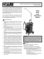
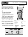
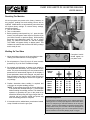
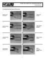
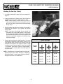
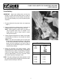
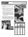
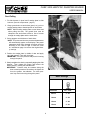
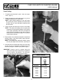
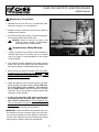
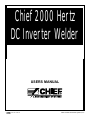
Chief 2000 Hertz
DC Inverter Welder
USERS MANUAL
R
A
INDUSTRIES COMPANY
2000 © Chief Automotive Systems, Inc.
CHIEF 2000 HERTZ DC INVERTER WELDER
R
USERS MANUAL
CHIEF'S LIMITED ONE-YEAR
WARRANTY & LIABILITY
Chief Automotive Systems, Inc. warrants for one year from date of installation and/or
purchase any of its products which do not perform satisfactorily due to defect caused by
faulty material or workmanship. Chief’s obligation under this warranty is limited to
the repair or replacement of products which are defective and which have not been misused, carelessly handled, or defaced by repair or repairs made or attempted by others.
CHIEF AUTOMOTIVE SYSTEMS, INC. DOES NOT ASSUME RESPONSIBILITY FOR ANY DEATH, INJURY OR PROPERTY DAMAGE RESULTING FROM
THE OPERATOR’S NEGLIGENCE OR MISUSE OF THIS PRODUCT OR ITS
ATTACHMENTS. CHIEF MAKES NO WRITTEN, EXPRESS OR IMPLIED WARRANTY WHATSOEVER OF MERCHANTABILITY OR FITNESS FOR A PARTICULAR PURPOSE OR OTHERWISE REGARDING THE EQUIPMENT OR
ANY PART OF THE PRODUCT OTHER THAN THE LIMITED ONE-YEAR
WARRANTY STATED ABOVE.
Returned merchandise requires a “RETURNED GOODS AUTHORIZATION NUMBER” on the package. Authorization numbers can be obtained by calling or writing the
Customer Service Department, Chief Automotive Systems, Inc. No returned merchandise will be accepted without an authorization number. All returned merchandise must
be shipped freight prepaid (and may be subject to a 15 percent handling and restocking
charge) to:
Chief Automotive Systems, Inc.
Attn: Returned Goods Dept.
1924 E. Fourth St.
or
P.O. Box 1368
Grand Island, NE 68802-1368
308-384-9747
Your Authorized
Chief Automotive Systems, Inc.
Representative
R
CHIEF 2000 HERTZ DC INVERTER WELDER
USERS MANUAL
This users manual is written to familiarize operators with the
safe and efficient operation of the Chief 2000 Hertz DC
Inverter Welder System. This resistance spot welder combines simplicity with multifunctional operations. It is easy to
use and its welding functions increase job performance and
shop productivity. It may be used with mild steel, galvanized
steel or high strength steel.
Chief
2000
Hertz
DC Inverter
Welder
Prior to using this welding system, all operators must read
this entire manual to not only become familiar with the system’s components but to also observe all safety, maintenance and troubleshooting precautions.
!
General Precautions:
1. Operation and maintenance are to be carried out in compliance with the recommendations listed in this users
manual.
2. All operators must be trained in the use of this welder.
3. Only qualified personnel must perform repairs and maintenance.
4. DO NOT attempt to dismantle or heat the gas spring of
the gun suspension system.
5. The electrical supply may reach 480 VAC (check voltage
on manufacturer’s name plate) and is a potential source
of danger if this manual’s recommendations are not followed.
6. Voltage in the machine may reach 670 VDC (indicated on
warning label inside of machine) and is a potential source
of danger if this manual’s recommendations are not followed.
7. The machine includes capacitors which store electrical
power even when the system has been disconnected
from power supply. See related precautions - page11.
8. Operator is responsible for ensuring proper care and
complying with the car manufacturer’s recommendations
relating to the protection of electrical, electronic or safety
devices (computer, car radios, alarms, air-bags, etc.).
9. Before any maintenance or repairs are made to equipment, electrical power supply must be cut off from the
welder by placing main switch (on front of machine) in the
“off” position and disconnecting machine from power supply.
10. Before any maintenance or repairs are made to equipment, compressed air supply should be cut off and
depressurized.
11. The electrodes, arms and secondary leads may become
extremely hot after use and may result in serious burns.
Allow these parts to cool before any repairs or maintenance is performed.
12. Follow maintenance recommendations listed in this manual. Repairs should be made immediately and all faulty
parts replaced.
Standards
All welding machines comply with EC standards and
international standards relative to resistance welders
and general specifications applicable to all transformers. All electrical components are UL listed.
!
CAUTION:
If precautions in this manual are not observed:
• Personnel will be endangered.
• Welding unit or other property may be damaged.
Chief Automotive Systems, Inc. is not responsible for
any injuries or property loss resulting from operation of
this unit under the following circumstances:
- Modification or neutralization of safety devices.
- Non-compliance of recommendations as listed
in this manual.
- Modification of equipment.
- Use of accessories other than those supplied
by Chief Automotive Systems, Inc.
1
CHIEF 2000 HERTZ DC INVERTER WELDER
USERS MANUAL
R
!
Rear Panel - Chief 2000 Hertz
DC InverterWelder
Electrical Precautions
The ground fault circuit interruptor (ground leakage circuit
breaker), fuses, gauges, wiring, power points, ground connection, and cut-off devices for the various power supplies,
must be in good condition and comply with the connecting
power of this machine as indicated on manufacturer’s
name plate.
!
Personnel Precautions.
1. Operators must wear face shield, gloves and non-flammable clothing for protection against sparks.
2. Electrode force may exceed 400 pounds. Keep body
clear of welding gun’s moving parts.
3. DO NOT wear rings, watches or any objects that may
conduct electricity as they can overheat and cause
severe burns.
4. Persons with medical implants should not come within
10 feet (3 meters) of the welder or the vehicle being
repaired when welder is in use.
5. All of the machine’s protective panels must remain in
place and be in good condition.
6. Warning labels must remain in place and be in good
condition. On request Chief supplies replacement
labels.
7. Operators must be knowledgeable of the operation of
the welder before beginning work.
8. Work area should be well-lit and free of obstacles with
access to emergency stop switch.
Unit Components (See Illustration Below)
1. Slide hammer.
2. Panel straightening accessory.
3. End piece for
dent pulling wedge
plates.
4. Electrode for seam
welds (series spots)
5. Electrode for stud welds,
2, 5 and 3mm.
6. Electrode for stud welds,
4 and 5mm.
IMPORTANT: In case of non-satisfactory welder operation, read this users manual for proper operating or
maintenance information. DO NOT remove panels to
look inside of machine. Place main switch to “off” position, disconnect machine from electrical and air power
sources and call a Chief authorized representative.
7. Electrode for moulding rivet
welds.
8. Electrode for copper
shrinking.
9. Electrode for washer
welds.
10. Electrode for spot welds
and welding of nuts.
11. Carbon electrode for heat
shrinking.
1
3
4
5
9
6
7
10
8
11
2
2
R
CHIEF 2000 HERTZ DC INVERTER WELDER
USERS MANUAL
Setting Up Welder
1. Make sure main switch at front of machine and
breaker at rear of machine are both in “off” position.
IMPORTANT: A qualified electrician must perform
the following:
• If machine will be used with three-phase supply, hard
wire it to connecting box or plug it to a 208/230 V
socket (3 phases + ground) with a minimum power of
50 amps, supplied by leads of at least 10 gauge.
• If machine will be used on single phase supply,
only two of the phase conductors will be used. Each
of the three phase conductors are identified by number (1, 2 or 3). For single phase supply, cut the end
of conductor number 3 and insulate it. Then hard
wire conductors 1 and 2 to a connecting box or to a
plug connected to a socket (208 / 230 V - single
phase + ground) with a minimum power of 60 A supplied by leads of at least 8 gauge.
Main Switch At
Front Of Machine
1
2
Control Panel At Front Of Machine
F
G
I
H
L K
J
2. Drain air supply line.
3. Connect the compressed air hose (with quick coupler)
to the air connector on back side of welding unit.
4. Set air pressure of line at 70 psi or 5 BAR.
M
5. Place breaker at rear of machine in “on” position.
6. Turn main switch on front panel (clockwise) to “on” position. DO NOT leave switch on positions “1” or “2”. Only
use “on” and “off”.
B
7. Press button in lower right hand corner of control panel
to switch control unit “on”. (See letter A at right.)
E
C
A
Control Panel Descriptions
8. Press pincer gun selection key. (See letter B at right.)
A:
B:
C:
D:
9. Operate pincer gun by pulling trigger located under the
handle. Electrodes should close. Then press trigger
located on top of handle. Electrodes should open wide.
!
D
E:
F:
CAUTION: Double-sided gun and single-sided pistol
are connected to current output. Welding can only be
done when correct gun is used with correct mode
setting. However, because the two tools are simultaneously supplied with current, it is important that
precautions be followed. When using double sided
gun, make sure single sided pistol and ground shoe
cable are placed on their supports and can not
touch each other. When using welding pistol, the
double- sided gun must be placed on its support.
G:
H:
I:
J:
K:
L:
3
Keyboard “on” switch.
M: Welding Pictographs
Selection of pincer gun.
(from left to right)
Selection of pistol.
• Welding of mild steel.
Job selection scroll to
• Welding of zinc coated
left.
steel.
Job selection scroll to right.
• Stud welding.
Welding time increase
• Nut welding.
key.
• Welding of moulding rivets.
Welding time decrease
• Seam welding.
key.
• Dent pulling.
Power increase key.
• Welding of pulling washPower decrease key.
ers.
Cable cooling automatic
• Pulse welding (gun) or
indicator.
bump shrinking (pistol).
Cable cooling manual
• Carbon heat shrinking.
indicator.
Cable cooling control
LED near pincer gun and pistol:
mode key.
Thickness of sheet to weld.
CHIEF 2000 HERTZ DC INVERTER WELDER
R
USERS MANUAL
Resetting The Machine
All work programs are preset at the factory; however, on
any program, welding time and welding current can be
modified. Modifications are automatically memorized and
will replace factory settings. To recover factory settings,
proceed as follows:
1. Turn off main switch.
2. Turn on main switch
3. Before pressing control panel key “on”, press simulta neously the two bottom center keys for selection of job
(see items D and E on previous page). While keeping
these two keys depressed, press “on” key of control
panel. The machine will switch “on” and the message
“INIT PARA” will appear briefly on display panel. This
indicates the machine has recovered its factory settings
and is ready for use.
Welding On Two Sides
Completed welds
should appear as
per photo at left.
1. Adjust and tighten the arms of the two-sided gun after
making sure electrodes are correctly aligned.
2. Set air pressure to 70 psi (5 bar) for 9” arms. Increase
pressure by 15 psi for each 4” additional length.
Basic Settings
3. Set program and thickness of sheets to be welded. In
case of different thicknesses, only consider the thinner
sheet. The power and welding time are preset and the
parameters will automatically appear on the display. If
preset parameters have been changed, set power and
time according to the chart at right or reset the timer as
indicated at top of this page to recover the original factory settings.
Thinner
Sheet
Thickness
0.8 mm
1.0mm
1.2mm
1.5mm
2.0mm
2.5mm
4. Position electrodes where welding is required and
pull trigger to complete welding process.
NOTE: A timer allows the trigger of the two sided gun
to be pulled and released during a 1.5 second span
without starting the welding process. This allows the
operator to reposition the gun on the parts to be
assembled. When pulling the trigger longer than 1.5
seconds, the gun remains closed and opens only
after the welding process is complete.
Mild Steel
Zinc Coated
Tim. - Pow.
Tim. - Pow.
Tim. - Pow.
8 - 65
10 - 70
10 - 77
16 - 80
22 - 85
30 - 95
6 - 55
10 - 60
12 - 67
14 - 70
16 - 85
18 - 92
14
18
20
24
30
36
-
60
65
72
75
85
92
HSS
Electrode Alignment:
A special work mode allows closing of gun without starting the
welding process to check proper alignment of electrodes. When
timer is on and pincer gun has been selected, use “D” Key (see
diagram - page 3) to select welding of mild steel (first pictograph
at left). Press “D” Key one more time. LED under pictograph will
start blinking showing the gun is at “no weld” position. The gun
can be closed for 5 seconds by keeping finger on trigger.
5. If electrodes stick to welded area, press button located
at top of handle to force the gun open.
4
CHIEF 2000 HERTZ DC INVERTER WELDER
R
USERS MANUAL
Two-Sided Gun And Assorted Electrodes
440mm Large
Throat Gap
330mm Roof
Arm Set
440mm Straight
Arm Set
330mm Narrow
Throat Gap
Arm Set
330mm Straight
Arm Set
220mm Straight
Arm Set
150mm Wheel
Well Arm Set
150mm
X-Centered
Large Throat Gap
Arm Set
5
CHIEF 2000 HERTZ DC INVERTER WELDER
R
USERS MANUAL
Welding On One Side (Pistol)
1. Fit welding electrode to pistol. (See unit components page 2.)
2. Clamp ground shoe to bottom piece of steel prior to
welding top piece of steel to bottom piece of steel.
NOTE: When applying a pistol weld to top piece of
steel, the ground shoe must be clamped to the bottom piece of steel to allow a flow of current through
the two parts.
3. Select program and thickness of sheets to be welded. If
thicknesses are different, only consider the thinner
piece of steel.
NOTE: The power and welding time are preset and
parameters will automatically appear on the display.
If the preset parameters have been changed set
power and time according to the chart at right or reset
the timer as indicated on page 4 to recover the origi nal factory settings.
4. Position the electrode at the desired location. It must be
positioned perpendicular to the welding location to prevent slippage. Apply sufficient force to prevent any gap
between the two parts. Pull trigger of pistol to begin
welding process. Release trigger to stop. After welding
is completed, hold pistol in place for approximately 2
seconds to create a forging effect and avoid rapid cooling of the spot.
Basic Settings
Mild Steel
Zinc Coated
HSS
Tim.-Pow.
Tps - Puls.
Tps.-Puls.
Thinner
Sheet
Thickness
NOTE: Pulsations are not recommended for single side
welding except for thick metal. Therefore, for welding of
high strength steel, use the same program and same
settings as those for zinc coated steel.
6
0.8 mm
16 - 60
8 - 65
6 - 60
1.0mm
18 - 65
10 - 70
10 - 65
1.2mm
24 - 72
10 - 77
12 - 72
1.5mm
28 - 75
16 - 80
14 - 75
CHIEF 2000 HERTZ DC INVERTER WELDER
R
USERS MANUAL
Seam Welding
IMPORTANT: Seam spot welding does not have the
strength of a MIG weld and should never be used for
structural welding. Due to its low emission of heat; however, seam spot welding is very useful for patching holes
on panels.
1. Fit proper electrode in the pistol. (See unit components
- page 2.)
2. Clamp ground shoe to bottom piece of steel prior to
welding top piece of steel to bottom piece of steel.
NOTE: When applying a pistol weld to top piece of
steel, the ground shoe must be clamped to the
bottom piece of steel to allow a flow of current
through the two parts.
3. Select program and thickness of sheets to be welded.
If thicknesses are different, only consider the thinner
piece of steel.
NOTE: The power and welding time are preset and
parameters will automatically appear on the display.
If the preset parameters have been changed set
power and time according to the chart at right or
reset the timer as indicated on page 4 to recover the
original factory settings.
Basic Settings
All Steel
Top
Sheet
4. Position the electrode at the desired location. Apply
moderate pressure and pull the trigger. Hold trigger for
approximately three pulses. Then gradually tilt the pistol
to the front to begin rolling the electrode. The advance
speed is approximately 1 inch per 4 seconds. Control
the advance speed by checking the heat.
NOTE: The seam welding process allows operator to weld
zinc coated steel and high strength steel with the same
program used for welding of mild steel.
7
Thickness
Tim. - Pow.
0.8mm
4 - 55
1.0mm
5 - 60
1.2mm
6 - 70
CHIEF 2000 HERTZ DC INVERTER WELDER
R
USERS MANUAL
Welding Of Studs, Nuts And Moulding Rivets
1. Fit appropriate electrode in the pistol. (See unit components - page 2.)
2. Clamp ground shoe to steel sheet (panel, etc.) prior to
welding a stud, nut or moulding rivet to the steel sheet.
NOTE: When applying a pistol weld, the
ground shoe must be clamped to the steel sheet to
allow a flow of current through the component (stud,
nut or moulding rivet) and the steel sheet.
3. Select program and thickness of sheet to be welded.
NOTE: The power and welding time are preset and
parameters will automatically appear on the display.
If the preset parameters have been changed set
power and time according to the chart at right or
reset the timer as indicated on page 4 to recover the
original factory settings.
4. Position the electrode at the desired location. It must be
positioned perpendicular to the welding location to prevent slippage. Apply moderate pressure for nut welding
and very low pressure for welding studs and moulding
rivets. Pull trigger to weld. The trigger can be released
at any time as welding is electronically controlled.
Basic Settings
All Steels
All Steels
All Steels
Tim.-Pow
Tim.-Pow.
Tim.-Pow
0.8mm
18 - 60
10 - 65
2 - 25
1.0mm
20 - 65
12 - 70
2 - 30
1.2mm
22 - 72
13 - 77
2 - 33
1.5mm
24 - 75
14 - 80
2 - 38
2.0mm
26 - 85
15 - 85
2 - 42
2.5mm
28 - 92
16 - 95
2 - 50
Thickness
8
CHIEF 2000 HERTZ DC INVERTER WELDER
R
USERS MANUAL
Dent Pulling
1. Fit slide hammer in pistol and fit wedge plate in slide
hammer. (See unit components - page 2.)
2. Clamp ground shoe to steel sheet (panel, etc.) prior to
welding wedge plate to dented portion of steel sheet.
NOTE: When welding wedge plate to steel sheet and
when pulling the dent, the ground shoe must be
clamped to the steel sheet to allow a flow of current
through the wedge plate and the steel sheet.
3. Select program and thickness of steel sheet.
NOTE: The power and time are preset and parameters
will automatically appear on the display. If the preset
parameters have been changed set power and time
according to the chart at right or reset the timer
as indicated on page 4 to recover the original factory settings.
4. Position the wedge plate in middle of dent and apply
very light pressure. Then pull the trigger.
IMPORTANT: Too much pressure may result in burning
through the panel.
5. Slowly straighten the dent by repeatedly tapping the slide
hammer. Then release the trigger and remove the
wedge plate by twisting the slide hammer.
IMPORTANT: Pressure must be constant during the
dent removal procedure. Remember, the lighter the
force, the greater the adhesion. Too much pressure may result in burning through the panel.
Basic Settings
All Steels
9
Thickness
Tim. - Pow.
0.8mm
2 - 22
1.0mm
2 - 24
1.2mm
2 - 28
1.5mm
2 - 30
CHIEF 2000 HERTZ DC INVERTER WELDER
R
USERS MANUAL
Panel Pulling
1. Fit washer weld electrode in pistol. (See unit components - page 2.)
2. Clamp ground shoe to steel sheet (panel, etc.) prior to
welding of washer(s) to the steel sheet.
NOTE: When welding washer(s) to the steel sheet,
the ground shoe must be clamped to the steel sheet
to allow a flow of current through the washer(s) and
the steel sheet.
3. Select program and thickness of sheet to be welded.
NOTE: The power and welding time are preset and
parameters will automatically appear on the display.
If the preset parameters have been changed set
power and time according to the chart at right or
reset the timer as indicated on page 4 to recover the
original factory settings.
4. Place washer in the electrode and position electrode at
desired location. (See photo below.) Apply light pressure and pull the trigger.
NOTE: If necessary, weld additional washers making
sure they are aligned with each other. (See Step 5.)
5. Use slide hammer equipped with hook tool to pull washers one by one or in a series by inserting a bar (1/4”
diameter) through the washers. (See photo at right.)
IMPORTANT: Pressure must be constant during the
dent removal procedure. Remember, the lighter the
force, the greater the adhesion. Too much pressure may result in burning through the panel.
Basic Settings
All Steel
Thickness
10
Tim. - Pow.
0.8mm
2 - 25
1.0mm
2 - 27
1.2mm
2 - 30
1.5mm
2 - 32
R
CHIEF 2000 HERTZ DC INVERTER WELDER
USERS MANUAL
Smoothing Out Bumps
1. Fit proper electrode in the pistol. (See unit components
- page 2.)
2. Clamp ground shoe to steel sheet (panel, etc.)
prior to smoothing out bumps in steel sheet.
NOTE: When smoothing out bumps in steel sheet, the
ground shoe must be clamped to the steel sheet to
allow a flow of current through the electrode and the
steel sheet.
3. Select program and thickness of steel sheet used.
NOTE: The power and welding time are preset and
parameters will automatically appear on the display.
If the preset parameters have been changed, set
power and time according to the chart at right or
reset the timer as indicated on page 4 to recover the
original factory settings.
Basic Settings
4. Place electrode on center of bump and pull the trigger.
(See photo at right.) Apply only light pressure at first;
however, increase it gradually during pulsations when
bump starts to collapse.
NOTE: Heat can be controlled by the force applied to
the bump. The greater the force, the lower the heat.
The lighter the force, the greater the heat.
Thickness
0.8mm
1.0mm
1.2mm
1.5mm
All Steels
All Steels
Tim. - Pow.
Tim. - Pow.
6
6
6
6
-
-
20
24
30
55
30
35
40
50
Carbon Heat Shrinking
3. Select program and thickness of steel sheets used. If
thicknesses are different, only consider the thinner
piece of steel.
NOTE: The power and welding time are preset and
parameters will automatically appear on the display.
If the preset parameters have been changed set
power and time according to the chart above or
reset the timer as indicated on page 4 to recover
the original factory settings.
1. Fit a carbon pencil in the pistol. (See unit components
- page 2.)
2. Clamp ground shoe to steel sheet (panel, etc.) prior
to carbon heat shrinking process.
NOTE: When applying carbon heat shrinking process
to steel sheet, the ground shoe must be clamped to
the steel sheet to allow a flow of current through the
carbon pencil and the steel sheet.
4. Position carbon pencil at desired location and pull trigger. Apply spiral movement from outside to inside of
zone to be tensioned.
IMPORTANT: Heating time is limited to 8 seconds.
Immediately following application of heat, wet the
area. The sudden cooling will shrink the steel.
11
CHIEF 2000 HERTZ DC INVERTER WELDER
R
!
USERS MANUAL
Maintenance Precautions:
1. Maintenance must be done by an authorized Chief
Automotive Systems, Inc. representative.
2. Respect all safety instructions and warning labels as
indicated in this manual.
2 and 3
1
3. For access to electronic housing, remove the top panel.
(See screws located under rubber mat.)
CAUTION: Before removing top panel read
following section entitled: Supplementary
Safety Warnings For Maintenance.
!
!
Supplementary Safety Warnings:
1. Voltage in machine may reach 670 VDC (indicated on
warning label inside of machine) and is a potential
source of danger if recommendations in this manual
are not followed.
2. This machine includes capacitors which store electrical
power even when the system has been disconnected
from power supply for a substantial period of time.
3. Before opening top panel of machine, place main switch
(located on front of machine) at “off” position and disconnect machine from main power supply. Also, turn off
breaker on back of machine. Both steps are mandatory.
4. Lower the lighting in the room and remove the panel.
(Bright lighting may affect visibility.) Check LED located on the PCB at rear of machine. (See reference
No. 1 in photo above.) This LED must be off. (No light
should be seen.) The presence of light indicates that
capacitors are still charged.
5. If light is not detected in LED, make a safety check
by shunting the two aluminum bars. (See reference
Nos. 2 and 3 in photo above.) For this operation, use
only an electrician’s tool (pincer or screwdriver) insulated up to 1000V. The purpose of this step is to discharge
the capacitors in case the LED is defective.
IMPORTANT: These precautions are essential every time
the machine has been connected (even for a short period of time) as capacitors can be charged in less than a
second. Also, capacitors may remain charged for several
days even if the machine has been disconnected.
12
CHIEF 2000 HERTZ DC INVERTER WELDER
R
USERS MANUAL
Specifications
Power Supply...............................................................190 / 230 V - 50 / 60 Hz
3 phase + ground
or single phase + ground
Transformer...................................................................2,000 Hz rectified current
Transformer Class........................................................H (180° C)
Maximum Welding Power.............................................47,3 kVA
Thermal Protection.......................................................Yes
Full Load Amps.............................................................60 A
Breaker For Welding Up To 1.5mm Sheet..................40 A Slow Action Type
Breaker For Use Of Full Power Of Machine...............60 A Slow Action Type
Supply Cable Up To 60 Foot Distance (*)...................3 x 10 Ga. + Ground (On 3 Phase Use)
From Main Breaker *
3 x 8 Ga. + Ground (On Single Phase Use)
Electrode Force.............................................................375 LBS. At 85 PSI (6 bars)
Dimension (With Pincer And Pistol Bracket)
W x D x H....................................................................27” x 30” x 41”
Total Weight (With All Accessories And Cables).......245 LBS.
* Due to low work rate of this type of machine (maximum permanent current = 3 minutes per
hour), the admissible wire size is lower than recommended by international standards for this type
of breaker as the standards refer to a permanent use.
13
CHIEF 2000 HERTZ DC INVERTER WELDER
R
USERS MANUAL
Diagnosis And Remedies
Fault
Possible Cause
Remedies
Welding control indicators do not
light.
Power supply fault.
Check condition of main power line (unit connection,
fuses, main circuit-breaker, etc.). If no power supply problems, call an authorized Chief representative.
Machine’s circuit breaker trips.
Weak power supply.
Inadequate electrical supply, too low initial voltage or
important drop of voltage during weld results in high supply amperage. Have installation checked (initial voltage,
length, size of wire, tightening of connections , etc.).
Check condition of main power line (unit connection,
fuses, main circuit-breaker, etc.).
Installation circuit breaker trips.
Too low breaker or weak power supply
Same as above. Change breaker to higher amperage type
if necessary. (60 amps - slow action type.)
Self test message.
Normal when machine starts.
Wait until machine finishes auto test.
Test OK message.
Normal when machine starts.
Machine is OK ready to work in few seconds.
Init Para message.
Appears after resetting timer.
Procedure has been successful.
Tool err. message.
Wrong tool selected on keyboard.
Select tool being used (gun/pistol) on keyboard.
Curr. Peak message.
Inadequate electrical supply.
Inadequate electrical supply, too low initial voltage or
important drop of voltage during weld results in high supply amperage. Have installation checked (initial voltage,
length, size of wire, tightening of connections, etc.).
Stop ° F message
Overheating.
Overheated cables, rectifier or transformer. Stop using
machine for approximately 30 minutes but let machine run
to allow fan to cool. If air does not flow in the cables, select
automatic cooling on keyboard.
Gun Sens. message
Faulty gun cable temp. sensor.
Automatic cooling of gun cables may be erratic. Use manual cooling control and call an authorized Chief representative.
Pist. Sens. message
Faulty pistol cable temp. sensor.
Automatic cooling of pistol cables may be erratic. Use
manual cooling control and call an authorized Chief representative.
Keyboard Err. message
Faulty keyboard (one key stuck).
Call an authorized Chief representative.
Gun Trig. message.
Faulty gun switch.
Gun switch stuck. Operate trigger to try to release the
switch. If no improvement, replace switch.
Pist. Trig. message
Faulty pistol switch.
Pistol switch stuck. Operate trigger to try to release switch.
If no improvement, replace switch.
14
CHIEF 2000 HERTZ DC INVERTER WELDER
R
USERS MANUAL
Diagnosis And Remedies..........continued
Fault
Possible Cause
Remedies
Dirty sheets (paint, primer, filler,
excessive rust, etc.)
Clean and remove excess paint, filler or rust.
Too low electrode force.
Increase welding effort.
Worn electrodes.
Clean, dress or replace electrodes.
Poor quality welding primer.
Use only high quality zinc welding primer “Saitek Z-Coat”.
DO NOT use a copper or aluminum-based primer.
Wrong settings.
Reduce welding time and increase welding power.
Inadequate power supply.
Inadequate electrical supply, too low initial voltage or
important drop of voltage during weld resulting in high supply amperage. Have installation checked (initial voltage,
length, size of wire, tightening of connections, etc.). Check
if several machines are not connected on same line and
operating simultaneously.
Poor connections.
Check that all connections are tight. (Welding cables on
gun, pistol and ground and on transformer output.)
Incorrect ground shoe position.
Make sure ground shoe is close to spot of weld and that it
is on bottom sheet and not on sheet where weld is to be
completed. Check temperature of sheet between spot of
weld and ground shoe. A temperature elevation of approximately 40° F after 4 spots indicates a poor return of current.
Inadequate cooling.
Check air pressure (70 PSI or 5 bars minimum). Make sure
air flows in cable. Let cables cool approximately 15 minutes and place cable cooling control on “manual” to allow
air flow from beginning of task if machine has to be used
for a long time. On automatic control position, the cooling
starts when cables begin to get hot.
Incorrect settings.
Reduce welding time and increase welding current.
Damaged electrodes requiring too
much current.
Clean, dress or replace electrodes.
Welding rate too fast.
Reduce welding rate.
Uneven “sticking” of dent pulling
electrodes and washers.
Uneven pressure during welding.
Maintain constant pressure.
Steel sheet under ground shoe
overheats or burns.
Insufficient contact zone or insufficient pressure under ground shoe.
Current must be spread spread evenly under ground shoe.
If steel sheet is thin, place a piece of metal between bottom of steel sheet and bottom jaw of ground shoe clamp
to provide a larger contact surface.
Poor quality welds: burnt spots
with cavities
Weak welding current.
Overheating of welding cables
15
CHIEF 2000 HERTZ DC INVERTER WELDER
R
USERS MANUAL
Diagnosis And Remedies..........continued
Fault
Single sided weld has a nice
appearance but is not consistent.
Excessive sparks when welding
with pincer gun.
Possible Cause
Remedies
Incorrect settings.
Reduce welding time and increase welding power.
Poor location of ground shoe.
Make sure ground shoe is close to spot of weld and that it
is on bottom sheet and not on sheet where weld is to be
applied. Check temperature of sheet between spot of weld
and ground shoe. An elevation of temperature of approximately 40° F after 4 spots indicates a bad return of current.
Heavy zinc coating of sheets.
Use setting for welding of zinc coated sheet. If necessary,
remove some of zinc.
Poor quality welding primer.
Use Saitek Z-Coat primer.
Insufficient effort of electrodes.
Increase air pressure (70PSI minimum with short arms).
16
R
P.O. Box 1368
Grand Island, Nebraska 68802 - 1368
Phone: 308-384-9747
Fax:
308-384-8966
INTAIRCO S.A.R.L.
CA de TREMBLAY CHARLES DE GAULLE
18, rue Henri FARMAN
93297 TREMBLAY EN FRANCE CEDEX
TEL 01 41 51 16 80
FAX 01 48 60 09 88
www.chiefautomotive.com
Chief reserves the right to alter product specifications
and/or package components without notice.
Form C2000 HDCIW UM (7/00)
Part No. 222010