1
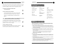
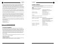
XAP IR Remote Control
Installation & Operation Manual
ClearOne Communications, Inc. ~ 1825 Research Way, Salt Lake City, UT 84119 ~ tel 1-800-945-7730 ~ fax 1-800-933-5107
ii
Table of Contents
Table of Contents
1
Introduction
Introduction
Introduction . . . . . . . . . . . . . . . . . . . . . . . . . . . . . . . . . . . . . . . . . . . . . . . . .1
Unpacking . . . . . . . . . . . . . . . . . . . . . . . . . . . . . . . . . . . . . . . . . . . . . . . . . . . . . . . . .1
Product Registration . . . . . . . . . . . . . . . . . . . . . . . . . . . . . . . . . . . . . . . . . . . . . . . . . .2
Professional Services Group . . . . . . . . . . . . . . . . . . . . . . . . . . . . . . . . . . . . . . . . . . . . .2
Installation . . . . . . . . . . . . . . . . . . . . . . . . . . . . . . . . . . . . . . . . . . . . . . . . .3
The XAP™ IR Remote Control system is designed to allow easy operation of XAP
products from your desk or conference table, rather than from the front panel or
G-Ware™ software of your ClearOne audio conferencing products or an expensive
external controller.
XAP IR Remote Receiver . . . . . . . . . . . . . . . . . . . . . . . . . . . . . . . . . . . . . . . . . . . . . . .3
Front Panel LEDs . . . . . . . . . . . . . . . . . . . . . . . . . . . . . . . . . . . . . . . . . . . . . . . . . . . .5
trol) and the base station infrared receiver. The remote control is used to operate or
Configuration . . . . . . . . . . . . . . . . . . . . . . . . . . . . . . . . . . . . . . . . . . . . . . . .5
customize certain features of the XAP system, such as connect, disconnect, dial a
Programming Functions . . . . . . . . . . . . . . . . . . . . . . . . . . . . . . . . . . . . . . . . . . . . . . . .5
Configuring G-Ware Remote Builder . . . . . . . . . . . . . . . . . . . . . . . . . . . . . . . . . . . . . . .6
Programming Example A . . . . . . . . . . . . . . . . . . . . . . . . . . . . . . . . . . . . . . . . . . . . . .8
Programming Example B . . . . . . . . . . . . . . . . . . . . . . . . . . . . . . . . . . . . . . . . . . . . . .10
telephone number, redial, activate speed dial, hook flash, adjust volume, and mute
It consists of two components: the handheld infrared transmitter (remote con-
the microphones.
The XAP IR Remote functions with various XAP stand-alone or combined systems. The remote’s default programming can be easily customized to fit your needs
Operation . . . . . . . . . . . . . . . . . . . . . . . . . . . . . . . . . . . . . . . . . . . . . . . . . . .12
Getting Started . . . . . . . . . . . . . . . . . . . . . . . . . . . . . . . . . . . . . . . . . . . . . . . . . . . . . .12
Remote Control Buttons . . . . . . . . . . . . . . . . . . . . . . . . . . . . . . . . . . . . . . . . . . . . . . . .13
Specifications . . . . . . . . . . . . . . . . . . . . . . . . . . . . . . . . . . . . . . . . . . . . . . . .15
Warranty . . . . . . . . . . . . . . . . . . . . . . . . . . . . . . . . . . . . . . . . . . . . . . . . . . .15
Compliance . . . . . . . . . . . . . . . . . . . . . . . . . . . . . . . . . . . . . . . . . . . . . . . . .16
Index . . . . . . . . . . . . . . . . . . . . . . . . . . . . . . . . . . . . . . . . . . . . . . . . . . . . . .18
by using G-Ware, the XAP system’s configuration software. In the event of a power
outage, the new programming will be stored in the receiver’s memory and will not
be lost or altered. The remote also provides positive feedback for the Mute LED and
In Use LED by actively monitoring the response of the controlled unit(s) and indicating the correct status of each function.
Professional Services Group
For additional help on how to install, set up, or operate the XAP IR Remote, please
contact ClearOne Technical Services Group at the number at the bottom of the
page. We welcome your comments so we can continue to improve our products and
serve your needs.
ClearOne Communications ~ 1825 Research Way ~ Salt Lake City, UT 84119
Technical Services
XAP IR Remote Control Installation and Operation Manual
ClearOne Part No. 800-170-050 June 2002 (Rev. 2.0)
© 2002 ClearOne Communications, Inc. All rights reserved. No part of this document may be reproduced in any
Telephone:
1.800.283.5936 (USA) or 1.801.974.3760
Fax:
1.801.977.0087
E-mail:
[email protected]
Web site:
www.clearone.com
form or by any means without written permission from ClearOne Communications. Printed in the United States
of America. ClearOne Communications reserves specific privileges. Information in this document is subject to
change without notice.
Technical Services Group ~ 1-800-283-5936 (USA) ~ 1-801-974-3760
Technical Services Group ~ 1-800-283-5936 (USA) ~ 1-801-974-3760
2
Introduction
Sales and Customer Service
3
Installation
Installation
Telephone:
1.800.945.7730 (USA) or 1.801.975.7200
Fax:
1.800.933.5107 (USA) or 1.801.977.0087
E-mail:
[email protected]
XAP IR Remote Receiver
Installation is simple. Plug the XAP IR Remote Receiver into the RS-485 Remote
ClearOne Communications EuMEA GmbH
Panel A or Remote Panel B connector located on the back of the ClearOne unit.
Leonhardstr. 16-18, D-90443 Nuremberg, Germany
Telephone:
+49 911 955159-0
Fax:
+49 911 955159-10
E-mail:
[email protected]
Product Registration
Please register your XAP IR Remote online by visiting www.clearone.com. When
your product is properly registered, ClearOne Communications is better able to serve
MUTE
IN USE
READY
you should you require technical assistance. Registration information is also used to
notify you of upgrades and new product information.
Figure 2. XAP IR Remote Control Receiver
Product Returns
If you need to return your XAP IR Remote unit to ClearOne for service, please call
the Technical Services Group to obtain a return authorization number.
Alternatively, you can connect the receiver to a network of ClearOne Control
Panels which are connected to one of the RS-485 ports on the rear of the ClearOne
unit. In this case, connect the IR receiver as the last device in the daisy chain.
Unpacking
Up to five control panels and one IR receiver can be connected to an RS-485 port.
You should have received the following items with your XAP IR Remote Control.
Refer to the table below for maximum cable runs. The distances indicated are
for category five twisted-pair cable.
R
ON
1
OFF
2
3
ABC
4
GHI
6
MNO
8
9
TUV
WXYZ
*
VOLUME
FLASH
SPEED
DIAL
MUTE
OFF
REDIAL
Installation & Operation Manual
MUTE
IN USE
READY
#
0
MUTE
ON
XAP IR Remote Control
DEF
5
JKL
7
PQRS
Infrared Remote Receiver
Part 910-170-150
PROGRAM
Manual
Part 800-170-050
CONFERENCE
CALL
Infrared Remote Transmitter
Part 460-160-005
+
AAA
-
+
AAA
-
AAA Batteries (2)
Part 590-002-001
# of Remote Devices
1
2
3
4
5
6
Maximum Distance
3,000 ft/914 meters
2,500 ft/762 meters
1,600 ft/488 meters
1,200 ft/366 meters
1,000 ft/305 meters
800 ft/244 meters
Figure 3. Category five cable run distances
Figure 1. XAP IR Remote Control System
Technical Services Group ~ 1-800-283-5936 (USA) ~ 1-801-974-3760
Technical Services Group ~ 1-800-283-5936 (USA) ~ 1-801-974-3760
4
Installation
Telephone
Set
MUTE
IN USE
XAP IR Receiver
OUTPUT 6
OUTPUT 7
OUTPUT 8
INPUT 5
INPUT 6
INPUT 7
INPUT 8
OUTPUT 1
OUTPUT 2
OUTPUT 3
OUTPUT 4
MIC 1
There are three LEDs on the front of the XAP IR Remote—Mute, In Use, and
• Mute. The Mute LED flashes red when microphones are muted (default). You
can program this LED to illuminate to another command in the Remote
Builder window of G-Ware. See Configuration (below) for more information.
SPEAKER
OUTPUT 5
Front Panel LEDs
Ready.
Analog
Telephone
Line
XAP 400
2A
5
READY
Speaker Connection
10W, 4 to 16Ω
VOLTAGE RANGE 100V-240V
FREQUENCY 50Hz/60Hz
Configuration
MIC 2
MIC 3
MIC 4
• In Use. The In Use LED glows red whenever a phone participant is on the
line. The programming of this LED cannot be changed.
= Microphone
1
2
3
4
Figure 4. Typical XAP IR Remote Receiver installation
• Ready. The Ready LED glows red when the receiver is connected to a XAP or
PSR1212 product, indicating the system is ready for a valid command. The
programming of this LED cannot be changed.
When a button is pressed, the Ready LED flashes, indicating a command has been
received.
DIP switch configuration
Located on the rear of the receiver are five DIP switches. These switches are default
programmed at the factory to allow the receiver to operate without adjustment
when it is connected to one of the RS-485 Remote Panel ports on the rear of the
Configuration
ClearOne conferencing unit.
If you are connecting the IR Remote receiver to a network of ClearOne Control
Panels (which are connected to one of the Remote Panel ports), ensure that DIP
switch 5 is set to on; this serves as the termination of the daisy chain, since the IR
Remote is always connected as the last device in the chain. Set DIP switches 1–4
As an example, if you have three Control
Panels connected to Remote Panel A and you want
to connect an IR Remote receiver to the daisy
chain, the receiver would be number 3 (the Control
Panels being numbers 0, 1, and 2). Therefore, the
DIP switch settings for the IR receiver would be
1=Off, 2=Off, 3=On, 4=On, and 5=On.
IR Remote Receiver Number
according to the table in Figure 5.
0
1
2
3
4
5
6
7
8
9
10
11
1
On
Off
On
Off
On
Off
On
Off
On
Off
On
Off
DIP Switch
4
3
2
On On On
On On On
Off On On
Off On On
On Off On
On Off On
Off Off On
Off Off On
On On Off
On On Off
Off On Off
Off On Off
The XAP IR Remote Control is programmed by default to operate a single XAP 400
with an amplifier and speaker connected to Output 8; however, it is easy to customize should you require different specifications. If you want to use the factory
defaults, proceed to Operation on page 12. Below are instructions for setting up the
remote control in ClearOne G-Ware software, the user interface for XAP products.
5
On
On
On
On
On
On
On
On
On
On
On
On
Figure 5. DIP switch settings
✍
Programming Functions
XAP IR Remote system defaults
The XAP IR Remote is programmed by default to operate the XAP 400/TH2
Telephone Interface as follows: The On, Off, 0-9, *, #, Flash, Redial, Speed Dial,
and Conference Call keys activate any XAP 400/TH2 on the expansion bus network
regardless of its type and device ID. This is because of the default ** programming,
which allows the selection of any device on the network.
✍
Buttons programmable in G-Ware are illustrated in Figure 12 (page 12).
Always connect the IR Remote receiver to the last Control Panel when connecting to
a daisy chain of Control Panels. Only the last device in a daisy chain should have the
last DIP switch set to On (to terminate the chain).
Technical Services Group ~ 1-800-283-5936 (USA) ~ 1-801-974-3760
Technical Services Group ~ 1-800-283-5936 (USA) ~ 1-801-974-3760
6
Configuration
Configuring G-Ware Remote Builder
1. Open the Remote Builder window in G-Ware by clicking the Remote Builder
Flow Screen button or Remote Builder toolbar button.
Configuration
7
6. Click the Active Command or Inactive Command button to set the command for operation when the button is active or inactive.
7. Select the Device Type, ID, and Command from their respective lists. When
you select a command, a description of it appears in the Command
Description box.
Figure 6. Remote
Builder Flow Screen
button
8. Select the command parameters from the argument lists. The parameters that
are available depend on the command selected. When you select an argument,
a description of it appears in the Argument Description box.
Figure 7. Remote
Builder toolbar button
Figure 8. Remote Builder window
9. Click the Apply button to apply the command to the selected Active or
Inactive Command button. Or, click Clear to reset the command to default
settings.
Repeat steps 5-9 for each additional button you want to configure.
2. Select a remote ID number from the Select Remote ID list and IR Remote
from the Select Remote Type drop-down lists. Note that the Select Remote
ID must correspond to the ID you established with the DIP switches (see
page 4).
10. Click Close to exit the Remote Builder.
3. Click Change Name to create a more descriptive name for the remote which
is displayed in addition to the remote ID number (limit 20 characters).
can be 40 digits long and can have a 20-character name. These numbers and labels
4. In the Telephone Interface section, select the Device Type and ID of the unit
(XAP 400 or XAP TH2) that you want the XAP IR remote to use when making and receiving calls. The default settings are ** which will select any telco
device found on the network. If you have multiple telco devices in your network, you must specify which unit will be used to make and receive calls so
that multiple telco devices won’t be activated.
can be called by a single command. Any valid touch-tone digit and the pause charac-
Speed dial
The XAP IR Remote Control system supports 10 speed dial numbers. Each number
are stored in non-volatile memory of the XAP conferencing unit and each number
ter (comma) can be stored. All speed dial numbers are empty except for Speed Dial
9, which is programmed with ClearOne’s technical support number, and Speed Dial
10, which is programmed with the conference calling services number. See pages
14-15 for information about using speed dial numbers.
5. Select the button or LED you want to program from the Select Button/LED
list. You can also select the button or LED by clicking directly on the picture
of the remote. (Selectable buttons are colored white.)
Technical Services Group ~ 1-800-283-5936 (USA) ~ 1-801-974-3760
Technical Services Group ~ 1-800-283-5936 (USA) ~ 1-801-974-3760
8
Configuration
To configure speed dial numbers
9
2. Select the remote ID number of the remote you want to program from the
Select Remote ID list and IR Remote from the Select Remote Type dropdown lists.
1. Click the Dial button in the G-Ware Flow Screen.
The Dial window opens.
3. Select the Volume Up button from the Select Button/LED list. You can also
select the button by clicking directly on the Volume Up button in the remote
control depiction.
2. Click Edit in the Speed Dial section. This opens
the Speed Dial Edit window.
3. Enter the name and number to dial in the appropriate fields.
Configuration
Figure 9. Dial button
4. Click Save to save changes and exit.
Programming Example A
This example illustrates how to configure the remote control to adjust the
4. Click the Active Command button to set the command for operation when
the button is active.
5. Select 7 (for XAP 400) for the device Type
from the Type drop-down list.
6. Select the appropriate ID of the unit from
the DID list.
speaker output (output 9) of a XAP 400.
7. Select RAMP from the Command dropdown list.
To program volume control of output 9
8. Select channel 9 from the Channel list.
1. Open the Remote Builder window in G-Ware by clicking the Remote Builder
Flow Screen button or Remote Builder toolbar button.
9. Configure the Group, Rate, and Target lists. The Group list indicates the location of the XAP 400 in a network. The Rate list indicates the number of dB
per second that the volume ramps up. The Target list indicates the target dB
increase, which is 6dB (a decibel level selected for purposes of this example).
10. Click the Apply button to apply the command to the selected Active
Command button.
To configure the Volume Down button, follow the same procedure, except in Step 3,
select the Volume Down button, and in Step 9, select -6 (dB) in the Target list. You
would select -6 because you want the Volume Down button to decrease the volume
to -6dB. This means the Volume Up/Volume Down range is 12dB.
Click Close to exit the Remote Builder.
Figure 10. Remote Builder screen with Volume Up button configuration
Technical Services Group ~ 1-800-283-5936 (USA) ~ 1-801-974-3760
Technical Services Group ~ 1-800-283-5936 (USA) ~ 1-801-974-3760
10
Configuration
Configuration
11
Programming Example B
This example illustrates how to configure the remote control to mute all mics on
multiple connected units (in this case, a XAP 400 with a device ID of 0 and a
XAP 800). In this example, the XAP IR Remote receiver is connected to the
XAP 400.
For the XAP 800: 5 * Mute * M 1
To mute multiple units
The unmute macro has the following command lines:
For the XAP 400: 7 * Mute * M 0
For the XAP 800: 5 * Mute * M 0
2. After you have created and saved the macros, open the Remote Builder
screen in G-Ware and select the appropriate remote ID number from the
Select Remote ID drop-down list and IR Remote from the Select Remote
Type drop-down list.
3. Select the Mute On button from the Select Button/LED list. You can also
select the button by clicking the Mute On button in the remote control
depiction.
4. Click the Active Command button to set the command for operation when
the button is active.
5. Select 7 (for the XAP 400) for the device Type from the Type drop-down list.
6. Select 0 for the device ID from the DID list.
7. Select MACRO from the Command drop-down list.
8. Select the macro number of the “mute on” macro you created from the
Macro list. The Macro Label field will reflect the name you have given the
macro.
Figure 11. Remote Builder screen with Mute LED configuration
9. Click the Apply button to apply the command to the selected Active
Command button.
To configure the Mute Off button, follow the same procedure, except in Step 3,
1. Create two macros (one to mute, one to unmute) to mute all microphone
inputs on all connected units. This is accomplished using the Macro Editor in
G-Ware. See the respective XAP 400 or XAP 800 manual for details about
using the Macro Editor.
select the Mute Off button, and in Step 8, select the macro number of the “mute
off” macro you created.
When you are finished, click Close to exit the Remote Builder.
The mute macro has the following command lines:
For the XAP 400: 7 * Mute * M 1, where 7=Type (XAP 400), *=DID
(Device ID), Mute=command, *=Channel, M=(Mic) Group, and 1=Mute
Mode (on).
Technical Services Group ~ 1-800-283-5936 (USA) ~ 1-801-974-3760
Technical Services Group ~ 1-800-283-5936 (USA) ~ 1-801-974-3760
12
Operation
13
Operation
Remote Control Buttons
Operation
While within 25–40 feet of the receiver, point the remote control toward the receiver
and press the buttons to operate.
Getting Started
Once your remote is connected to your XAP system, you have configured it, and the
To place a call
Ready LED is lit, you can start using your remote control.
1. Press Telephone On (green) button. The In Use LED illuminates.
Operation is easy and straightforward. Please consult the diagram on the following page to learn how each button on your remote works.
TELEPHONE ON
(green) button
Press to get a dial tone.
ON
1
NUMBERS
Use these buttons to
dial telephone numbers.
* VOLUME UP
Press to raise the audio
level in the room. Can
also be programmed to
control the level of any
input or output.
* MUTE ON
Press to mute all
microphones in the room
(default). Can be programmed
to mute specific
microphones in the room or
to mute other devices.
FLASH
Provides a hook flash for
accessing features on your
PBX. Allows conferencing if
the PBX is set up to
accommodate a hook flash.
OFF
2
3
ABC
DEF
4
5
6
GHI
JKL
MNO
7
8
9
PQRS
TUV
WXYZ
*
2. Wait to hear dial tone.
3. Dial telephone number using dial pad. Or, press
Speed Dial and the location of the speed dial
number.
TELEPHONE OFF
(red) button
Press to end a call.
FLASH
SPEED
DIAL
MUTE
OFF
REDIAL
PROGRAM
CONFERENCE
CALL
3
DEF
4
5
6
GHI
JKL
MNO
7
8
9
PQRS
TUV
WXYZ
*
0
Press Telephone Off (red) button. The In Use LED
OFF
To adjust the volume in the room
·
MUTE
ON
2
ABC
extinguishes.
* VOLUME DOWN
Press to lower the audio
level in the room.
VOLUME
1
To end a call
·
#
0
ON
– or –
·
* MUTE OFF
Press to turn the mute
function off.
* PROGRAM
This button is not factoryconfigured. However, it
can be programmed in
G-Ware to execute a
command.
Press the Volume Up button to raise the volume.
Press the Volume Down button to lower the volume.
To mute microphones
·
Press the Mute On button.
MUTE
ON
Mute LED will flash on receiver when the Mute function is
active. This function mutes all microphones in the room.
* CONFERENCE CALL
This button is defaulted to
Gentner's conference call
number, which is preset in
Speed Dial 10.
SPEED DIAL
Press to dial telephone
numbers that have been
programmed into the
SPEED DIAL function. See
Configuration, page 5.
To turn off mute
·
REDIAL
Press to dial the last
telephone number.
Press the Mute Off button.
MUTE
OFF
Mute LED on receiver will turn off when mute function is off.
To access features from a PBX
* Programmable button in G-Ware software.
·
Press the Flash button.
FLASH
Figure 12. XAP IR Remote Control button descriptions
Technical Services Group ~ 1-800-283-5936 (USA) ~ 1-801-974-3760
Technical Services Group ~ 1-800-283-5936 (USA) ~ 1-801-974-3760
#
14
Operation
Please consult your PBX owner’s manual for specific requirements of your individual phone system. G-Ware can be used to adjust the hook flash duration to match
15
Specifications
Specifications
your PBX. This setting is located in the Telco Config window in G-Ware.
To redial the last telephone number dialed
·
Press the Redial button.
REDIAL
To dial a number stored in speed dial
·
Press the Speed Dial button. Select location (0-9) of the speed
dial number with the appropriate numeral button. Speed dial
SPEED
DIAL
memories 1-9 correspond to buttons 1-9; speed dial 10 uses
Transmitter
Receiver
System
Dimensions (LxWxH):
8" x 2.125" x 1.19"
20.3 x 5.4 x 3 cm
Dimensions (LxWxH):
5" x 2.75" x 1"
12.7 x 7 x 2.54 cm
Range:
25–40 feet (7.5–12 meters)
from transmitter to receiver
Battery type:
2 AAA
Power:
Powered by the XAP or
PSR1212 system
Angle of acceptance:
90°–120°
Battery life:
Approximately 1 year
button 0.
✍
The Program button is not factory-configured. However, it can be pro-
PROGRAM
grammed in G-Ware to execute a command.
Call services (stored in Speed Dial 10, which uses the 0 button).
Warranty
ClearOne Communications, Inc. (Manufacturer) warrants that this product is free of
defects in both materials and workmanship. Should any part of this product be defective, the Manufacturer agrees, at its option, to:
To dial a conference call center
The Conference Call button is defaulted to dial ClearOne’s Conference
Operating temperature:
32°F to 122°F/0°C to 50°C
Compliance approvals:
FCC, Industry Canada, and
CE
In order for the Speed Dial function to work, a telephone number must be programmed into the XAP product. Please see Speed Dial on page 7.
To change the button programming of your XAP IR Remote
Cable length:
6'/1.8 m
CONFERENCE
CALL
A. Repair or replace any defective part free of charge (except transportation charges) for a
period of one year from the date of installation for the end-user, provided the owner returns
the product to the Manufacturer at the address set forth below. No charge will be made for
parts or labor during this period;
B. Furnish replacement for any defective parts in the product for a period of one year from
the date of original purchase. Replacement parts shall be furnished without charge, except
labor and transportation.
This Warranty excludes assembled products not manufactured by the Manufacturer
whether or not they are incorporated in a Manufacturer product or sold under a
Manufacturer part or model number.
This warranty is void if:
A. The product has been damaged by negligence, accident, act of God, or mishandling, or has
not been operated in accordance with the procedures described in the operating and technical instructions; or,
B. The product has been altered or repaired by other than the Manufacturer or an authorized
service representative of the Manufacturer; or,
C. Adaptations or accessories other than those manufactured or provided by the Manufacturer
have been made or attached to the product which, in the determination of the
Manufacturer, shall have affected the performance, safety or reliability of the product; or,
D. The product’s original serial number has been modified or removed.
Technical Services Group ~ 1-800-283-5936 (USA) ~ 1-801-974-3760
Technical Services Group ~ 1-800-283-5936 (USA) ~ 1-801-974-3760
16
Compliance
17
Compliance
NO OTHER WARRANTY, EXPRESS OR IMPLIED, INCLUDING WARRANTIES OF MERCHANTABILITY OR FITNESS FOR ANY PARTICULAR USE, APPLIES TO THE PRODUCT. MANUFACTURER’S MAXIMUM LIABILITY HEREUNDER SHALL BE THE
AMOUNT PAID BY THE END-USER FOR THE PRODUCT. No person or entity authorized to
assume any obligation or other liability in connection with the products. No action, regardless
of form, arising out of or relating to the product or this Warranty, may be brought by end-user
more than one (1) year after the cause of action has accrued.
European Compliance
Manufacturer shall not be liable for punitive, consequential, or incidental damages, expenses,
or loss of revenue or property, inconvenience, or interruption in operation experienced by the
end user due to a malfunction in the purchased product. No warranty service performed on any
product shall extend the applicable warranty period.
Application of Council Directive(s):
1999/5/EC Radio equipment and
Telecommunications Terminal Equipment
(R&TTE) Directive
Manufacturer’s Name:
ClearOne Communications, Inc.
In case of unsatisfactory operation, the end-user shall promptly notify the Manufacturer at the
address set forth below in writing, giving full particulars as to the defects or unsatisfactory
operation. Upon receipt of such notice, the Manufacturer will give instructions respecting the
shipment of the product, or such other matters as it elects to honor this warranty as above provided. This warranty does not cover damage to the product during shipping and the
Manufacturer assumes no responsibility for such damage. All shipping costs shall be paid by
the customer.
Manufacturer’s Address:
1825 West Research Way
Model No.:
XAP IR Remote Control
This warranty extends only to the original end user and is not assignable or transferable. This
Warranty is governed by the laws of the State of Utah, without regard to the conflicts of interests provisions thereof.
ClearOne Communications, Inc.
1825 Research Way
Salt Lake City, Utah 84119
Compliance
This equipment has been approved in accordance with Council Directive 1999/5/EC “Radio
Equipment and Telecommunications Equipment.”
Conformity of the equipment with the guidelines below is attested by the CE mark.
EC Declaration of Conformity
Salt Lake City, Utah 84119 U.S.A.
Standard(s) to which Conformity is declared:
89/336/EEC “Electromagnetic Compatibility (EMC) Directive”:
EN 55022: 1994 (Emissions)
Specification for limits and methods of measure
ment of radio interference characteristics of
information technology equipment.
EN 55024: 1998 (Immunity)
Information technology equipment – Immunity
characteristics – Limits and methods of
measurement.
EN 61000-4-2: 1995/A1:1998
Electrostatic Discharge
EN 61000-4-3: 1996/A1:1998
Radiated RF Immunity
EN 61000-4-4: 1995
Electrical Fast Transients
FCC Part 15 compliance
This equipment has been tested and found to comply with the limits for a Class B digital
device, pursuant to Part 15 of the FCC rules. These limits are designed to provide reasonable
protection against harmful interference when the equipment is operated in a commercial environment. This equipment generates, uses, and can radiate radio frequency energy and, if not
installed and used in accordance with the instruction manual, may cause harmful interference
to radio communications. Operation of this equipment in a residential area is likely to cause
harmful interference, in which case the user will be required to correct the interference at
his/her own expense.
Changes or modifications not expressly approved by ClearOne Communications, Inc. could void
the user’s authority to operate the equipment.
Safety Information
CAUTION: Users should not attempt to make such connections themselves, but should contact
the appropriate electrical inspection authority, or electrician, as appropriate.
Technical Services Group ~ 1-800-283-5936 (USA) ~ 1-801-974-3760
Technical Services Group ~ 1-800-283-5936 (USA) ~ 1-801-974-3760
18
19
Index
Index
B
G
buttons 14
G-Ware 6-11
Conference Call 14
Flash 13
I
Mute Off 13
In Use LED 5, 13
Mute On 13
installation 3
number 13
M
Off 13
Mute LED 5, 13
On 13
Program 14
O
Redial 14
Operation 12
Speed Dial 14
Volume Down 13
P
Volume Up 13
programming 5
C
R
ClearOne’s Conference Call services 14
Ready LED 5
configuration 5
S
D
Speed dial 7, 8, 13, 14
DIP switches 4
Technical Services Group ~ 1-800-283-5936 (USA) ~ 1-801-974-3760
Technical Services Group ~ 1-800-283-5936 (USA) ~ 1-801-974-3760