1
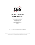
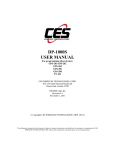
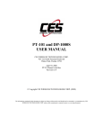
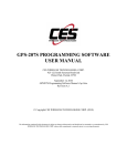
GPS-206 USER MANUAL CES WIRELESS TECHNOLOGIES, CORP. 925-122 South Semoran Boulevard Winter Park, Florida 32792 May 5, 2011 GPS206 Manual v3p0.doc Revision 3.0 © Copyright CES WIRELESS TECHNOLOGIES CORP. (2011) The information contained in this document is subject to change without notice and should not be construed as a commitment by CES WIRELESS TECHNOLOGIES CORP. unless such commitment is expressly given in a covering document. REGULATORY COMPLIANCE FCC The GPRS modem was tested and certified to meet FCC Parts 15 in a stand-alone configuration, which demonstrated that it complies with Part 15 emission limits. The GPS-206 uses an Enfora manufactured GPRS modem. FCC Part 22 & Part 24 is covered by the "modular approval" process for a transmitter. This approach, described by FCC Public Notice DA 00-131407 released June 26, 2000, is intended to afford relief to equipment manufacturers by eliminating the requirement for obtaining a new equipment authorization for the same transmitter when installed in a new device. In order to approve it without additional FCC certification approvals, the installation must meet the following conditions: For the transmitter to meet the MPE categorical exclusion requirements of 2.1091, the ERP must be less than 1.5 watts for personnel separation distance of at least 20 cm (7.9 in). Therefore, the maximum antenna gain cannot exceed +3.3dBi. If greater than 1.5 watts exists, then additional testing and FCC approval is required. R&TTE The GPRS modem has been fully tested and complies with all the requirements of EN301 489-1, EN301 489-7 and EN60950-1:2001. Compliance to EN301 511 has been demonstrated by testing on the GPS-206. Disclaimer The information and instructions contained within this publication comply with all FCC, GCF, PTCRB, R&TTE, IMEI and other applicable codes that are in effect at the time of publication. The GPS-206 uses an Enfora manufactured GPRS modem. CES Wireless Technologies disclaims all responsibility for any act or omissions, or for breach of law, code or regulation, including local or state codes, performed by a third party. CES Wireless Technologies strongly recommends that all installations, hookups, transmissions, etc., be performed by persons who are experienced in the fields of radio frequency technologies. CES Wireless Technologies acknowledges that the installation, setup and transmission guidelines contained within this publication are guidelines, and that each installation may have variables outside of the guidelines contained herein. Said variables must be taken into consideration when installing or using the product, and CES Wireless Technologies shall not be responsible for installations or transmissions that fall outside of the parameters set forth in this publication. CES Wireless Technologies shall not be liable for consequential or incidental damages, injury to any person or property, anticipated or lost profits, loss of time, or other losses incurred by Customer or any third party in connection with the installation of the Products or Customer's failure to comply with the information and instructions contained herein. © CES Wireless Technologies Corp – 2011 Page 2 of 23 CHANGE LOG Date Author 2010-10-01 Doug Hamilton 2010-10-19 2011-05-05 Doug Hamilton Doug Hamilton Description Added this Change Log. Added description of the LEDs in Section 1.6 3.6.2: Changed descriptive requirements for the Garmin interface. Added information on the Auxiliary Expansion Cable © CES Wireless Technologies Corp – 2011 Page 3 of 23 TABLE OF CONTENTS REGULATORY COMPLIANCE ...............................................................................................................2 CHANGE LOG...........................................................................................................................................3 TABLE OF CONTENTS.............................................................................................................................4 TABLE OF FIGURES.................................................................................................................................5 TABLES......................................................................................................................................................5 WARRANTY..............................................................................................................................................6 COPYRIGHT .............................................................................................................................................6 1.0 Introduction...........................................................................................................................................7 1.1 About the GPS-206............................................................................................................................7 1.2 About This Manual............................................................................................................................7 1.3 Basic Package Contents.....................................................................................................................7 1.4 Accessories........................................................................................................................................7 1.5 System Requirements........................................................................................................................7 1.6 GPS-206 Front and Back View.........................................................................................................7 2.0 Specifications.........................................................................................................................................9 2.1 System Information...........................................................................................................................9 2.2 GPRS Packet Data.............................................................................................................................9 2.3 GPS Functionality.............................................................................................................................9 2.4 Environment......................................................................................................................................9 2.5 Certifications.....................................................................................................................................9 2.6 SIM Card/Interface/I/O......................................................................................................................9 2.7 Power................................................................................................................................................9 2.8 Battery Specifications......................................................................................................................10 3.0 Installation...........................................................................................................................................10 3.1 Mounting Dimensions.....................................................................................................................10 3.2 Installing Cables..............................................................................................................................11 3.2.1 HRNS057 - 8-Pin I/O Connector.............................................................................................11 3.3 Installing the SIM (Subscriber Identity Module) Card.....................................................................12 3.4 Connecting the GSM/GPRS and GPS Antenna...............................................................................12 3.5 Connecting Power...........................................................................................................................13 3.6 Connecting a Garmin Nüvi PND to the GPS-206............................................................................13 3.6.1 Requirements...........................................................................................................................14 3.6.2 GPS-206 Programming............................................................................................................14 3.6.3 Cables.......................................................................................................................................15 3.7 Auxiliary Expansion Cable .............................................................................................................15 3.7.1 Schematic.................................................................................................................................15 3.7.2 Specifications...........................................................................................................................15 3.7.3 Wiring......................................................................................................................................16 4.0 Support................................................................................................................................................17 Appendix 1 – Cable Wiring Diagrams.......................................................................................................18 Appendix 2 – Troubleshooting..................................................................................................................20 A2.1 Verifying the GPS-206 has Established a GSM Connection.........................................................20 A2.2 Verifying the GPS-206 has Established a GPRS Connection.......................................................20 A2.3 Verifying the GPS-206 has Acquired a GPS Satellite Fix............................................................21 Appendix 3 – Configuration Form.............................................................................................................22 Cellular Carrier Information..................................................................................................................22 Server Information................................................................................................................................22 Position Reporting.................................................................................................................................22 Ignition Reporting.................................................................................................................................23 GeoStatuses...........................................................................................................................................23 © CES Wireless Technologies Corp – 2011 Page 4 of 23 TABLE OF FIGURES Figure 1: Front View of the GPS-206. Note the SIM Card Access..............................................................8 Figure 2: Back View of the GPS-206..........................................................................................................8 Figure 3: Mounting dimensions of a GPS-206...........................................................................................10 Figure 4: 8-Pin Connections......................................................................................................................12 Figure 5: Garmin FMI section in the DP-1000S........................................................................................15 Figure 6: Auxiliary Expansion Cable Schematic.......................................................................................15 Figure 7: Wiring for Power Only (HRNSxx).............................................................................................18 Figure 8: Wiring for Power and Serial Interface (PRG-xx).......................................................................18 Figure 9: Wiring for Power and I/O...........................................................................................................19 TABLES Table 1: 8-pin I/O Connector Functionality...............................................................................................11 Table 2: Manufacturer Part Numbers to Build Cables...............................................................................12 Table 3: Auxiliary Expansion Cable Specifications...................................................................................16 © CES Wireless Technologies Corp – 2011 Page 5 of 23 WARRANTY Complete Warranty details can be found at the CES Wireless web site: www.ceswireless.com CES Wireless Technologies Corp., (CES Wireless), warrants this product to be free from defects in material and workmanship for 12 months from date of shipment. If such malfunction occurs, it will be repaired or replaced (at our option) without charge for materials or labor if returned to the factory. This warranty does not apply to parts damaged due to improper use- including accident, neglect, unreasonable use, and improper installation - or to unauthorized alterations or modifications of the equipment. It does not extend to damage incurred by natural causes such as lightning, fire, floods, or other such catastrophes, or to damage caused by environmental extremes, such as power surges and or transients. It does not extend to microprocessors if is determined that the failure of a micro is due to static damage, application of improper voltages to the unit, or other problems not related to circuit design. In such case or in the case of a desire to update the micro to a different version of software, such request must be specified in writing, and there will be a charge agreed upon by both parties. Software products provided by CES Wireless are only compatible with currently supported Microsoft® operating systems. This product is warranted to meet published specifications and to operation as specified only properly programmed and installed. CES Wireless is not responsible for any operational problems caused by system design, cellular coverage, outside interference, or improper installation. A qualified two-way radio technician or engineer must complete installation and programming of this CES Wireless product. Equipment for repair must be returned to the factory, freight prepaid, only with prior authorization. Please call 407-679-9440 for an RMA number. A brief letter describing the nature of the defect should be included with the merchandise. Repair by other than CES Wireless will void this warranty. In-warranty merchandise must be shipped, freight prepaid, to CES. CES Wireless will return the repaired or replaced equipment prepaid to purchaser, within the United States. Outside the US the customer must pay freight. This warranty applies to the original purchaser of the equipment only. CES Wireless is not liable under this warranty, or any implied warranty, for loss of use or for other consequential loss or damage experienced by the purchaser. Some states do not permit the exclusion or limitation of implied warranties or consequential damages. This warranty provides special legal rights, and the purchaser may have other rights that vary from state to state. Complete current Warranty details can be found at the CES Wireless web site: www.ceswireless.com COPYRIGHT The information in this manual and any software in this product remain the property of CES Wireless Technologies Corp. Duplication or disclosure is not permitted without the prior written consent of CES Wireless. CES Wireless reserves the right to change products, specifications, and installation data at any time, without notice. All information contained in this document is carefully prepared and offered in good faith as a guide in the installation, operation, use and servicing of our products. Installers must insure that the final installation operates satisfactory, within relevant regulatory requirements. We accept no responsibility for incorrect installations. Windows XP and 2000 are registered trademarks of Microsoft. All other trademarks are the property their respective owners. A CES Wireless publication. © Copyright CES Wireless 1997-2011 © CES Wireless Technologies Corp – 2011 Page 6 of 23 1.0 Introduction The GPS-206 is one of the smallest and most economical GPS asset tracking devices available today. This device is neither weather, dust or splash proof. GPS and event data is made available on-board the GPS-206 for transmission to FleetLinc (CES web based subscriber fleet management service). The GPS-206 can also be licensed for use with POWER-trak™ PC/Server software. Please contact CES for further direction with this. 1.1 About the GPS-206 The GPS-206 is an Automated Vehicle Locating (AVL) device that utilizes a GSM/GPRS cellular modem and a Global Positioning Satellite (GPS) module. Working together, these technologies allow the GPS206 to simultaneously act as a stand alone GPS reporting device and wireless data retrieval unit. The GPS-206 provides a flexible AVL solution with two Inputs and one Output. The GPS-206 is designed to work as a stand-alone device in a vehicle. It requires DC power and an antenna (GPS and GSM). 1.2 About This Manual This manual contains instructions on how to install and configure the GPS-206. Please follow the instructions closely to avoid damaging the GPS-206. 1.3 Basic Package Contents The basic package will contain the following: • • 1.4 GPS-206 - GPS/GSM/GPRS Tracking and Fleet Management Device 8-pin interface connector with DC cable (HRNS-xx) Accessories The following accessories are available from CES Wireless Technologies: • • • • • • • • 1.5 ANT-xx Magnetic mount, combo, multi band GSM/GPS antenna ANT-xx Through-hole/fixed mount, combo, multi band GSM/GPS antenna ANT-xx Loose/covert, combo, multi band GSM/GPS antenna ANT-xx Fixed mount, GSM only antenna ANT-xx Magnetic mount, GPS only antenna ANT-xx Fixed mount, GPS only antenna PRG-xx Programming Cable - 8-pin Serial I/O cable with DB-9 Connector DP-1000S Programming Software (can be downloaded from the CES FTP site, and is also available on CD-SOFT1 CD). System Requirements It is necessary to have a computer running Windows 2000, Windows XP or Windows Server 2003 to program the device. The system must include a serial port in order to configure the GPS-206. 1.6 GPS-206 Front and Back View Front View: On the front of the GPS-206 is the GSM SIM Card Access. Note: the SIM Card Lock on the right side of the access window. To the right of the SIM Card Access are three LEDs. The functionality of these LEDs is (left to right): © CES Wireless Technologies Corp – 2011 Page 7 of 23 USR1 (Green) – This LED indicates the state of the GSM connection. If blinking the GPS206 is attempting to establish the connection. If solid the GSM connection has been established. PWR GPS (Red) – When this LED is illuminated it indicates that the GPS206 has power. USR2 (Red) – This LED indicates the state of the GPS fix. If illuminated the GPS206 has established a position fix from satellites in the GPS satellite constellation that are viewable from its current location. Figure 1: Front View of the GPS-206. Note the SIM Card Access. Back View: On the back of the GPS-206 are 3 connectors. On the left is the GPS Antenna connector (FAKRA Blue Coding C Antenna Connector for 3.3 Vdc GPS). In the middle is the 8-pin I/O connector (described in detail later in this manual). On the right is the Cellular Antenna (FAKRA Bordeaux Violet Coding D Antenna Connector for GSM). Figure 2: Back View of the GPS-206. © CES Wireless Technologies Corp – 2011 Page 8 of 23 2.0 Specifications Note: Specifications subject to change without notice. 2.1 System Information Dimensions Weight Housing: TX Power: 64.8 x 61 x 25.6mm L x W x H: Rugged plastic enclosure Class 4 (2W @850/900 MHz) Class 1 (1W @1800/1900 MHz) 850/900/1800/1900 Frequency: 2.2 GPRS Packet Data Mode: Protocol: Coding Schemes: Packet Channel: 2.3 Class B, Multislot 10 GSM/GPRS Rel 97 AMR Rel 99 CS1-CS4 PBCCH/PCCCH GPS Functionality Connector: Antenna: 2.4 Fakra 3.3V Active Environment Operating: Storage: Humidity: Vibration: 2.5 -30°C to +85°C -40°C to +85°C Up to 95% non-condensing In accordance with SAE J1211 Certifications FCC: GCF: PTCRB: Industry Canada CE Mark Emark RoHS Compliant 2.6 Part 15, 22 & 24 Version 3.27.0 Version 3.12.0 Yes Yes Yes Yes SIM Card/Interface/I/O SIM Access: GSM Antenna: I/O Connector: 2.7 External Fakra 10 Pin 2 User Inputs (0-40V) 1 Output (0-3V) Ignition Sense Serial Data in/out Power Band Mode Ave (mA) Peak (A) GSM 850/900 1TX/RX 250 1.6 © CES Wireless Technologies Corp – 2011 Page 9 of 23 GSM 1800/1900 2.8 Idle <40 1TX/RX 215 Idle <40 1.3 Battery Specifications The GPS-206 uses power either from the vehicle battery, or from an optional internal battery. The battery specifications are as follows: Nominal voltage: 3.6 VDC Nominal Capacity: 230 mAH when discharged at 46mA to 2.5V Maximum and Normal Charge voltage Minimum discharge voltage: Charge current: 3.0 4.2 V 2.5V 100mA Installation The instructions in this section describe the hardware installation of the GPS-206. To install the GPS-206 in a vehicle follow these steps: • • • • Choose a convenient location in the vehicle – either in the trunk or interior of a vehicle. Avoid locations that might expose the GPS-206 to excessive heat or moisture. Hold the GPS-206 in place and mark the location for mounting screw holes Using the markings as a guide, drill mounting holes in those positions Align the GPS-206 in the drilled holes and secure it with mounting screws The GPS-206 is NOT a waterproof or sealed device. Care must be taken to ensure that the device is kept away from water and other liquids. The GPS-206 can be mounted inside a weather proofed box if necessary. 3.1 Mounting Dimensions Figure 3: Mounting dimensions of a GPS-206 © CES Wireless Technologies Corp – 2011 Page 10 of 23 The GPS-206 should be used as a template to mark screw holes for installation. The mounting holes are designed for a number 8 screw. 3.2 Installing Cables To ensure proper operation of the GPS-206 please follow these precautions: • • • • • Remove power from the GPS-206. Do not create sharp bends, loops or crimps in the cables. Attach all cables to the vehicle and equipment in such a way as to reduce stress or wear caused by the vibration generated by moving vehicles. No more than a combined total of ten (10) pounds force can be applied to the GPS-206 connectors. Properly terminate all power cables. 3.2.1 HRNS057 - 8-Pin I/O Connector HRNS057 is an 8-pin external I/O connector and cable. This connector provides power and can be used to interface the GPS-206 with other devices. (Note crimp tool needed and pins – part number). CES Wireless Technologies can also provide optional cables with connectors. The part numbers vary with the cable’s intended use. Please contact your CES Wireless Technologies sales or support executive for more information. You may also build your own cable. Table 1 describes the functionality of this 8-pin connector. CES recommends using 20-gauge wire when building the connector. Pins that are not planned for usage should be left open without anything connected to them. Pin Number 1 2 3 4 5 6 7 8 Functionality Switched Power (Ignition) Serial Data In (RS232) Serial Data Out (RS232) Ground Unswitched Power (Battery) Input 1 Input 2 Output 1 (Default state is High) HRNS057 Color Codes White No Connection Co Connection Black Red Blue Green Brown Table 1: 8-pin I/O Connector Functionality The following figure shows the pin connections for the 8-pin connector. © CES Wireless Technologies Corp – 2011 Page 11 of 23 Figure 4: 8-Pin Connections The manufacturer part numbers for the parts needed to build the cables is noted in the following table. Item Connector Pins Manufacturer Molex Molex Crimp Tool Molex Part Number 43025-0800 43030-0008 20-24 AWG 43030-0011 26-30 AWG 63819-0000A Table 2: Manufacturer Part Numbers to Build Cables 3.3 Installing the SIM (Subscriber Identity Module) Card The SIM card is an integral part of any GSM terminal device. The SIM card may be installed by simply inserting the SIM card in the SIM slot provided in the front of the device. With the SIM locking mechanism on the right, the SIM card is inserted into the GPS-206 with the notch on the SIM card on the left and going in first. NOTE: Not all DP-1000S are provided with SIM cards. The SIM card will be provided by CES Wireless Technologies only if GSM/GPRS data service is purchased along with the device. If purchasing the SIM card separately take steps to ensure that the SIM card is provisioned by the operator for data. It should also be provisioned for SMS if this functionality is desired. NOTE: Always take care to protect the SIM card. The GPS-206’s GSM/GPRS related functionality will not operate without the SIM card installed. Ensure the power to the GPS-206 is disconnected before inserting the SIM card. Failure to do so might result in an unusable GPS-206 or a damaged SIM card. 3.4 Connecting the GSM/GPRS and GPS Antenna The GSM/GPRS/GPS combo Antenna is available from CES Wireless Technologies in three versions: magnetic mount, through-hole or loose/covert. These antennas are: • • ANT-06 ANT-07 Magnetic mount, combo, multi band GSM/GPS antenna Through-hole/fixed mount, combo, multi band GSM/GPS antenna © CES Wireless Technologies Corp – 2011 Page 12 of 23 • ANT-13 Loose/covert, combo, multi band GSM/GPS antenna • • • ANT-19 ANT-01 ANT-02 Fixed mount, GSM only antenna Magnetic mount, GPS only antenna Fixed mount, GPS only antenna - The GSM/GPRS antenna connector on the GPS-206 is a FAKRA Bordeaux Violet Coding D antenna connector. The antenna must be connected to the connector labeled “GSM”. - The GPS antenna connector on the GPS-206 is a FAKRA Blue Coding C Antenna Connector. The antenna must be connected to the connector labeled “GPS”. Ensure the power to the GPS-206 is disconnected before connecting the GPS or GSM/ GPRS antenna. Failure to do so might result in an unusable GPS-206. 3.5 Connecting Power The GPS-206 has an input voltage range of 7 - 40 V DC. The power and ignition pins can support 7 - 40 V DC input voltage. The user has an option to connect these wires depending on the desired functionality. Described below are the desired functionality and their associated wire connecting procedure: Power to the GPS-206 can be supplied in three different methods, depending upon the application. GPS-206 Always ON • Connect the power and ground wires of the GPS-206 to the battery leads. The GPS-206 will always remain ON as long as the battery lasts. In addition, the GPS-206 will remain on until its internal lithium-ion battery is depleted (approximately 1 hour). • The GPS-206 will be non-operational when the input voltage and current requirements are not met (battery drains – both external and internal). • The Ignition wire has to be left open (not connected). GPS-206 Turns Off when Ignition Turned Off • Connect the power line of the GPS-206 to an auxiliary power source, i.e. ignition. • Connect the ground wire to the chassis or negative terminal of the battery • The Ignition wire has to be left open (not connected). GPS-206 with Ignition Turned Connected to Provide Ignition On/Off Events • Connect the power and ground wires of the GPS-206 to the battery. • Connect the ignition wire of the GPS-206 to an auxiliary power source, i.e. ignition. • Device goes through a reset upon ignition on. 3.6 Connecting a Garmin Nüvi PND to the GPS-206 Do not attempt to enter route information or adjust the Garmin PND while driving. Failure to pay full attention to the operation of your vehicle could result in death, serious injury or property damage. You assume total responsibility and risk for using this device. This interface FMI v2 PND being requires the Garmin FMI v2. Not all GARMIN PNDs with FMI v2 support all commands available. Please verify the Protocol Support Data of the Garmin used. © CES Wireless Technologies Corp – 2011 Page 13 of 23 A Garmin Nüvi Personal Navigation Device (PND) may be used in conjunction with the GPS-206 providing the capability to 1. Send text messages from the PND to the host application (i.e. PT3) • Text messages can be entered on the PND using its on screen keyboard and then sent to the host application. 2. Receive text messages from the host application • A text message can be entered in the host application and then sent to the display or inbox of the PND. 3. Driver login and logout • Using a numeric ID the driver of the vehicle can log in and out. This information is sent to the host application. 4. Driver status • The status of the driver can be sent from the PND to the host application. The statuses are defined in the host application and sent to each device. By pressing the desired status the driver can change their status from (for example) In Service to En Route or At Job and so on. 5. Stop processing • Stops (destinations) can be sent from the host application to the PND. Thus, the PND can be provided with a route to follow for the day or for just the next destination. 3.6.1 Requirements The interface of the GPS206 to a Garmin requires the following 1. Interface cable • The cable required varies by the Garmin Nüvi PND. Please contact CES for a quote on the cable required. 2. Garmin Nüvi that supports the Garmin FMI v2. • Please refer to the Garmin website for information on compatible devices (www.garmin.com). 3. Purchase of the Garmin FMI password for the GPS206. • This unlocks the interface to the Garmin FMI in the GPS-206. • The password is unique for each GPS-206. The IMEI of each GPS-206 is required to obtain the correct password that device. 3.6.2 GPS-206 Programming To activate the GPS-206 to provide Garmin support, follow two simple steps. 1. Enable the feature using the CES DP-1000S Software 2. Enter the unique Password obtained from CES or your Dealer that activates the Garmin functionality Enabling: To program the GPS-206 for Garmin support the Enable Garmin FMI checkbox in the Garmin FMI group on the GPS tab of the DP-1000S must be checked. Password: The password to unlock the Garmin FMI functionality must be entered in the Garmin FMI Password edit box. Note: If the GPS-206 is being reprogrammed and the password to unlock the Garmin support was sent previously then it does not need to be sent again. On the GPS tab in the DP-1000S programming software is a section titled “Garmin FMI”. © CES Wireless Technologies Corp – 2011 Page 14 of 23 Figure 5: Garmin FMI section in the DP-1000S 3.6.3 Cables Since the different Garmin Nüvi PNDs use different interface cables the cabling information will be included with the interface cable when purchased from CES. 3.7 Auxiliary Expansion Cable The Auxiliary Expansion Cable (CES P/N: HRNS-062) for the GPS-206 adds 6 additional inputs and 2 outputs to the already rich feature set of the device. The Auxiliary Expansion Cable passes the existing inputs, output and ignition sense in addition to providing the additional functionality. 3.7.1 Schematic Below is a schematic of the Auxiliary Expansion Cable. Figure 6: Auxiliary Expansion Cable Schematic Cable 1: This cable connects to the GPS-206. Cable 2: This cable passes the existing GPS-206 Inputs (1 and 2) , the existing Output (1) and also has the 2 additional Outputs on it (2 and 3). Cable 3: This cable passes the existing Ignition input and also has the 6 additional Outputs on it (7 through 12). Cable 4: This cable provides Power and Ground to the GPS-206. There are two additional wires. These are reserved for future use. 3.7.2 Specifications Power Low Power Digital Inputs Digital Outputs 8 to 32 VDC 15 mA 8 (2 on GPS-206 plus 6 on Auxiliary Expansion Cable 1 (Open collector on GPS-206) plus 2 on Auxiliary © CES Wireless Technologies Corp – 2011 Page 15 of 23 Size Expansion Cable (Open collector 400 mA) 1.96” x 1.95” x 0.8” Table 3: Auxiliary Expansion Cable Specifications 3.7.3 Wiring The additional inputs and outputs on the Auxiliary Expansion Cable are wired in the same manner as the existing inputs and output on the GPS-206. Refer to Appendix 1, Figure 9 for more information. © CES Wireless Technologies Corp – 2011 Page 16 of 23 4.0 Support If you need help, we are easily accessible …. Telephone: Call 407-679-9440, and ask for product support. Fax: 407-679-8110 Email: [email protected] Skype: Please email [email protected] to obtain your currently assigned support engineer’s Skype address. Product support may ask you to E-MAIL a copy of the programmed parameters to us for analysis. To do this, go to FILE on the DP-1000S main menu, and click on SAVE AS. Note the path to the saved file in the save file dialog. Attach this file to an e-mail and send it to you product support representative or to the e-mail address noted above. Product support may ask you to PRINT a copy of the programmed parameters, and fax to for analysis. To do this, go to FILE on the DP-1000S main menu, and click on PRINT. Support Resources: www.ceswireless.com FTP Site: Please go to www.ceswireless.com and register for an FTP site User Name and Password © CES Wireless Technologies Corp – 2011 Page 17 of 23 Appendix 1 – Cable Wiring Diagrams Figure 7: Wiring for Power Only (HRNSxx) Figure 8: Wiring for Power and Serial Interface (PRG-xx) © CES Wireless Technologies Corp – 2011 Page 18 of 23 Figure 9: Wiring for Power and I/O © CES Wireless Technologies Corp – 2011 Page 19 of 23 Appendix 2 – Troubleshooting All the troubleshooting steps require the DP-1000S to be in “Manual Mode”. To enable this mode select the Program menu and select “Mode – Manual”. If this selection is not shown the software is in this mode already. The software can return to automatic mode by selecting the Program menu and then selecting “Mode – Auto”. A2.1 Verifying the GPS-206 has Established a GSM Connection To verify that the GPS-206 has established a GSM connection follow these steps. Is the antenna attached? Is the SIM card installed? The SIM card must be installed to establish a connection. In the DP-1000S, select the Commands tab. This selection is only displayed when the software is in Advanced Mode. Click on the “Verify GSM Status” button. The GPS-206 will reply in the communications text box. If you do not get a reply from the GPS206 verify that it has power and that the correct serial port is selected in the software. GPS-206 response: the GPS-206 responds with “+CREG: followed by two parameters, comma separated. o The desired response is “+CREG: 0,1” or “+CREG: 0,5”. o Parameter 1 0: disable network registration unsolicited result code 1: enable network registration unsolicited result code 2: enable network registration and location information unsolicited result code +CREG o Parameter 2 0: not registered, ME is not currently searching a new operator to register to 1: registered, home network 2: not registered, but ME is currently searching a new operator to register to 3: registration denied 4: unknown 5: registered, roaming o If the desired response is not received please discuss the programming of the SIM card with your cellular service provider. A2.2 Verifying the GPS-206 has Established a GPRS Connection To verify that the GPS-206 has established a GPRS connection follow these steps. Is the antenna attached? Is the SIM card installed? The SIM card must be installed to establish a connection. In the DP-1000S, select the Commands tab. This selection is only displayed when the software is in Advanced Mode. Click on the “Verify GPRS Status” button. The GPS-206 will reply in the text box at the bottom of the software. If you do not get a reply from the GPS-206 verify that has power and that the correct serial port is selected in the software. GPS-206 response: the GPS-206 responds with “%CGREG: followed by two parameters, comma separated. o The desired response is “%CGREG: 0,1” or “%CGREG: 0,5”. o Parameter 1 0: disable network registration unsolicited result code 1: enable network registration unsolicited result code +CGREG 2: enable network registration and location information unsolicited result code +CGREG © CES Wireless Technologies Corp – 2011 Page 20 of 23 Parameter 2 0: not registered, ME is not currently searching a new operator to register to 1: registered, home network 2: not registered, but ME is currently searching a new operator to register to 3: registration denied 4: unknown 5: registered, roaming o If the desired response is not received please discuss the programming of the SIM card with your cellular service provider. If the desired response is received but there is still an issue then the GPRS Activation needs to be verified. o Click on the Verify GPRS Activation button. o The GPS-206 response will be “$NETIP:” followed by 3 IP Addresses. For example, the GPS-206 should return something similar to this: $NETIP: "166.214.220.151", "066.102.163.232", "066.209.010.202" o If AT$NETIP returns all zeros, send the following command: AT$CGEER. This can be done by typing the command into the “Command to send” field in the Other section on the Commands tab. There are three common responses: $CGEER: no PDP reject cause (Everything should be working OK) $CGEER: requested service option not subscribed (APN is incorrect or SIM has not been enabled for data mode.) $CGEER: user authentication failed (username and/or password is incorrect.) o If these three IP Addresses are not returned received please discuss the programming of the SIM card with your cellular service provider. The information form the CGEER command may assist the carrier in determining the cause of the issue. o A2.3 Verifying the GPS-206 has Acquired a GPS Satellite Fix To verify that the GPS-206 has acquired a GPS Satellite fix follow these steps. Please note that it does take a few minutes for the GPS receiver to acquire a fix the first time. After that it should acquire a fix fairly quickly. Is the antenna attached? Does the antenna have a clear view of the sky? The GPS-206 cannot establish a GPS fix if the antenna is inside a building or if the sky is obscured by trees, buildings, tunnels, etc. It is also quite difficult for it to establish a fix if the antenna has only a partial view of the sky (i.e. it is near a window). In the DP-1000S, select the Commands tab. This selection is only displayed when the software is in Advanced Mode. Click on the “Read GPS” button. The GPS-206 will reply in the communications window. If you do not get a reply from the GPS206 verify that has power and that the correct serial port is selected in the software. GPS-206 response: the GPS-206 responds with a series of sentences that are produced by the internal GPS receiver. Of particular interest is the “$GPRMC” sentence which should be the next to last sentence that is produced. o “$GPRMC,,V,,,,,,,,,,N*53” is a sample of an invalid sentence. o “$GPRMC,042159.00,A,2835.1039,N,08118.3645,W,000.0,000.0,090407,03.7,W,A*03” is a sample of a valid sentence. o For information on the “GPRMC” sentence please search the internet. Entering “GPRMC Sentence”, without the quotes, into your favorite search engine should return the desired results. © CES Wireless Technologies Corp – 2011 Page 21 of 23 Appendix 3 – Configuration Form Revision 1.0. May 5, 2011 Cellular Carrier Information Select the cellular carrier from the list of carriers whose programming information is known to CES. Otherwise, enter the required information. If purchasing cellular service from CES no entry is required. Carriers AT&T (Cingular) Required information if the cellular carrier is not in the list above. APN: User Name: Password: Gateway Number (for SMS): Server Information If not using FleetLinc the following information is required. The Server must have a static IP Address. The Port used must be routed correctly through the firewall/router and the server must also have this port open. Server’s Static IP Address Port (UDP) Position Reporting Position reporting intervals are determined by the values of 3 parameters. These are Minimum Time, Maximum Time and Distance. The default programming is to send position every 5 minutes when the vehicle has moved 1000 feet and to send every hour when it is idle. If fixed time interval reporting is desired all that is required is the minimum time interval. Please note that sending position uses data and if this done too frequently it is quite possible that there will be data usage overages. These can get quite costly. Use Fixed Time Interval position reporting. Time interval: Report more frequently while moving and less while idle or parked. Moving time interval: Idle time interval: , Distance required for movement: . , Our default values for these parameters are as follows. These parameters were calculated from reviewing the usage patterns of hundred of companies and thousands of mobile devices. Fixed Interval 5 minutes Report more frequently while moving 1 minute while moving 60 minutes while idle 1000 feet (~305 meters) required for movement © CES Wireless Technologies Corp – 2011 Page 22 of 23 Ignition Reporting If the Ignition Input (aka switched power) will be connected to the vehicle’s ignition as well as having the power connection connected to the vehicle’s battery then the device is capable of reporting the state of the ignition as it changes. Enable Ignition reporting. Notes: (1) the connections to the vehicle’s power and ignition must be made; (2) the reporting of ignition state does use data. Be sure to consider the effect of this on the cellular data plan. GeoStatuses The GPS205, GPS206 and PT101 are all capable of storing 25 GeoStatuses. This form is for the basic GeoStatus configuration. It is assumed that the default values for some parameters are acceptable. GeoStatus No. 1 2 3 4 5 6 7 8 9 10 11 12 13 14 15 16 17 18 19 20 21 22 23 24 25 Latitude Longitude Radius Other For other advanced features including SMS Messaging, advanced input reporting, etc. please contact CES. © CES Wireless Technologies Corp – 2011 Page 23 of 23