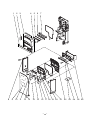
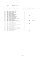
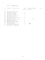
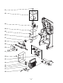
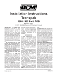
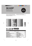
1
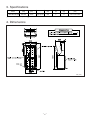
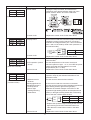
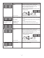
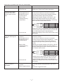
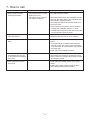
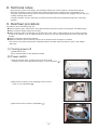
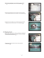
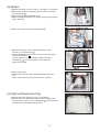
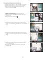
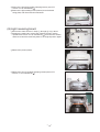
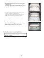
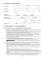
April 2006 No. U122 HAND DRYER HAND BOOK (For HONG KONG) Model: FOR DEALERS JT-SB216DS-W-AUS Nameplate Repair work should be performed by the manufacturer, its service agent or similarly qualified person in order to avoid a hazard. Notice: The term of validity is one year from the issued date. Contents Safety precautions.....................................................................3-4 1. Features................................................................................. 4 2. Names and functions of the hand dryer's components.......... 5 2-1 Configuration diagram and appearance diagram ............. 5 2-2 Operating procedure......................................................... 5 3. Specifications......................................................................... 6 4. Dimensions ............................................................................ 6 5. Wiring diagrams..................................................................... 7 6. Troubleshooting................................................................ 8-12 7. How to call ........................................................................... 13 8. Technical notes .................................................................... 14 9. Overhaul procedure........................................................ 14-20 10. Sequence timing chart ......................................................... 21 11. Description of circuit operation ....................................... 21-22 12. Circuit diagram and items to check ................................ 23-24 13. Board diagram and items to check ...................................... 25 14. Parts list.......................................................................... 26-34 Safety precautions ●Please read the following items carefully before using this product, and perform the maintenance and repair work of the product correctly and safely. ●The types and levels of the dangers from mishandling this product are categorized and indicated by the signs shown below. Warning Items that may cause death or serious injury if the product is mishandled. Caution for electric shock Turn off the power If it is absolutely necessary to inspect the circuitry while turning on electricity, exercise caution not to touch live parts. (Touching live parts may cause electric shock.) • Be sure to turn off the ground fault circuit interrupter and the power switch of the product's main body prior to starting repair work. (The charge voltage in the circuitry remains for another minute or so, even after the power is turned off and the LED is unlit; therefore, wait for at least 1 minute before disassembling the product.) Caution for electric shock Modification prohibited (Not turning off the power may cause electric shock.) Never modify the product. (Modifying may cause electric shock, fire, and/or injury.) Use proper parts and tools Prohibited Use the parts listed in the service parts list of the subject model with appropriate tools when repairing. Conduct electric work correctly • Use the designated electric wires, and conduct electric work according to the Electrical Equipment Technical Standard, Internal Wiring Regulation, and Installation Work Guide. • Be sure to check whether the terminals and fixed wiring are securely connected. (Improper connection or installation may cause electric shock and/or fire.) Implement by always following instructions Implement by always following instructions (Using improper parts and tools may cause electric shock, fire, and/or injury.) Implement by always following instructions Check insulation Upon completing repair work, always measure an insulation resistance. Verify that it is at least 1 MΩ, and then turn on the power. (Inadequate insulation may cause electric shock.) Implement by always following instructions Scratches and deterioration Be sure to replace scratched and/or deteriorated fixed wiring and lead wires. (They may cause electric shock and/or fire.) Avoid misuse Implement by always following instructions • This appliance is not intended for use by young children or infirm persons unless they are adequately supervised by a responsible person to ensure that they can use the appliance safely. • Young children should be supervised to ensure that they do not play with the Implement by always appliance. following instructions Caution Items that may cause injury and/or damage to buildings and/or fixtures if the product is mishandled. Wear gloves Always wear a pair of gloves during inspection or repair work. (Not wearing gloves may cause injury.) Implement by always following instructions —3— Items to check during repair work • Inspect the condition of the earth. Correct it if improperly grounded. Also, check to see if a ground fault circuit interrupter is being installed. If not, install one. • Check to see whether or not the air filter and the drain tank are installed securely in place. • Do not leave a towel or other object in the hand-drying area. • Never place any object on the main body nor cover it. • Make sure that the product is not being used in any of the following locations: Locations where the temperature can exceed 0°C to 40°C. Locations where the humidity can exceed 5%RH to 95%RH. Locations where the unit may come into direct contact with water. Locations where the unit is under direct or strong sunlight. (May cause sensor to malfunction.) Locations where there is a lot of condensation. Do not use with chemicals (detergents, etc.) on your hands. (This may reduce the productive life of the unit.) Do not use in locations where corrosive, neutral, or reductive gases are present. (This may reduce the productive life of the unit and/or cause malfunctions.) Locations where solt damage may occur. Places lower than -20m or higher than 2000m above sea level. ●Upon completing repair work, verify that the product operates normally. Clean the product's main body and surrounding area, and notify the customer of the completion of the repair work. 1. Features 1 Speed drying Equipped with a turbo fan, the hand dryer blows away drops of water on the hands with a high-speed jet air from a large air volume, high-speed rotary DC brush-less blower, thus quickly draying the hands. 2 Easy to use The rubbing of the hands is no longer necessary. With the hand dryer, you can dry both hands by just inserting and then removing them slowly. 3 Hygienic • The hand dryer is automatically started by a sensor. Thus, there is no need to touch the hand dryer with your wet hands. It is very hygienic. 4 Antibacterial • The hand dryer uses a silver inorganic substance; thus, maintaining an antibacterial effect for an extended period of time. • The hand dryer meets the antibacterial effect standard defined by the Society of Industrial Technology for Antimicrobial Articles (SIAA). 5 Easy maintenance The hand dryer does not require a paper or cloth towel, thus eliminating the dumping of paper waste and the exchanging of towels. Also, the hand dryer is easy to clean. 6 Highly safe with mischievous use prevention timer To prevent continuous operations of the hand dryer by mischievous use or malfunction, it has a built-in timer that automatically stops drying upon reaching a specific period of time. 7 Economical The monthly electricity expense is the only expense the hand dryer requires. Thus, it is extremely economical for use over an extended period of time. —4— 2. Names and functions of the hand dryer's components 2-1 Configuration diagram and appearance diagram 2-2 Operating procedure With both hands open, insert them all the way in. The unit will come on automatically. Pull them out slowly, letting the air blow the water off. Repeat until dry —5— Pull hands all the way out. 3. Specifications Model Voltage (Vac) Frequency (Hz) Phase Power consumption (W) Current (A) Weight (kg) Dimensions (W ✕ D ✕ H) (mm) JT-SB216DS-W-AUS 220-240 50-60 single-phase 650 4 11 300 ✕ 220 ✕ 687 The drain tank capacity is 0.8 . 4. Dimensions Unit (mm) —6— 5. Wiring diagrams —7— 6. Troubleshooting Precautions when diagnosing malfunctions: ● When servicing, be sure to recreate the malfunction 2 to 3 times before initiating repairs. ● When servicing, always keep proper footing. ● When servicing, make sure that the cord is pulled out of the outlet, or the breaker is off if no mains connector is built in the product, so as no electrical shock or injury to occur. Pay sufficient attention when working on the product. ● Always connect the power wire properly. ● When removing the circuit board, always hold it at both ends and remove carefully so as not to apply force to the surface mounted parts. ● When removing the circuit board, be careful of the metal edges on the board. ● When inserting or extracting pin connectors on the circuit board, hold the entire housing. Do not pull on the lead wires. ● If a malfunction of the printed circuit board is suspected, check for any broken copper-printed pattern, burnt or discolored parts. ● Be sure to restore same settings as those on the one just replaced. * The names of the parts indicated are compatible with those listed under the "Name of part" in the chapter "Parts list". Description of error modes below LED1 LED2 [●] Lit [●] Unlit [✩] Blinking (0.4 sec on/0.4 sec off) [✻] Fast blinking (0.1 sec on/0.1 sec off) Error mode display LED1 LED2 Power Inspection ● ● (No display, no operation) Cause Check procedure and action to take 1.Power off 2.Current fuse 3.Motor temperature fuse • Is the power supply connected? • Is the power switch on? • Measure the resistance between the current fuses on the control board. Measured value Decision/action 0Ω Normal * Replace the control board if the measured resistance value is other than the normal value shown in the table at right. • Is the motor's lead wire connector connected? • Measure the resistance between the motor's two "blue" lead wires. Measured value Decision/action 0Ω Normal * Replace the motor if the measured resistance value is other than the normal value shown in the table at right. —8— Error mode display LED1 LED2 Power Inspection ● ● (No display, no operation) LED1 LED2 Power Inspection ● ● (Operates, but no display) Cause Check procedure and action to take 4.Power switch • Unplug the relay connector, and measure the resistance at two places between each pair of the power switch's "brown" and "blue" lead wires. 5.Control circuit • Replace the control circuit if other than above. 1.Display board • Is the sensor's lead wire connector (CN2) connected? • Unplug the control circuit's CN2 (3-pin connector), measure the voltage between pins 1 and 2 as well as pins 1 and 3 of the CN2 by diode check (measure on the lead wire side). Measured value Decision/action 1.5 to 1.8V Normal LED1 LED2 Power Inspection ✩ ✩ (Heat sink overheat) 2.Control circuit • Replace the control circuit if other than above. 1.Filter clogged with dust • Is the filter clogged with dust and the like? → If so, clean the filter. • Are the temperatures of the control circuit and electronic parts too high? → If so, turn OFF the power switch and lower the temperatures to normal temperatures (40 ˚C or less). • Replace the control circuit if other than above. 2.PTC operation (control circuit) 3.Control circuit LED1 LED2 Power Inspection ✩ ● (Mischievous use prevention timer) 1.Continuous operation 2.Stained sensor's windows 3.Disengaged sensor 4.Displaced sensor's board positions 5.Sensor light emitting/receiving diode failure • When the operation time exceeds 30 seconds, the operation stops by the activated mischievous use prevention timer. • Are the sensor's three windows stained? • Is the sensor's lead wire connector connected? • Are the sensor's board positions displaced (top/bottom light emitting boards, light receiving board)? • Measure the forward voltages of the LEDs on the top/bottom light emitting boards and the photo diode (PHD) on the light receiving board with a measuring device that has a diode check function. – side + side 6.Control circuit Tester Item name Measured value Decision LED 0.9 to 1.2V Normal Photo diode 0.5 to 0.8V Normal * Replace the top/bottom light emitting boards and the light receiving board if the measured values are other than the normal values shown in the table above. • Replace the control circuit if other than above. —9— Error mode display LED1 LED2 Power Inspection ● ✩ (Motor lock) Cause Check procedure and action to take 1.Motor • Measure the winding resistance. (Measure the resistance values between "black and white," "red and black," and "white and red" wires of the 1-pin connector coming from the motor.) * Replace the motor if the measured values are other than the normal value shown in the table at right. Measured value Decision Approx. 3.4 to 3.7Ω Normal LED1 LED2 Power Inspection ✩ ● (Overvoltage, low voltage, power supply frequency detection) LED1 LED2 Power Inspection ● ✻ (Microcomputer RAM abnormality) LED1 LED2 Power Inspection ● ● (Overcurrent detection) 2.Control circuit • Replace the control circuit if other than above. 1.Excess voltage applied • Is a rated power supply voltage of 220 to 240 V being applied? • Is a rated power supply voltage of 220 to 240 V being applied? • Is a power supply frequency 50 or 60 Hz? 2.Low voltage 3.No power supply frequency 4.Control circuit • Replace the control circuit if other than the above. 1.Control circuit • Replace the control circuit. 1.Motor • Measure the winding resistance. (Measure the resistance values between "black and white," "red and black," and "white and red" wires of the 1-pin connector coming from the motor.) * Replace the motor if the measured values are other than the normal value shown in the table at right. Measured value Decision Approx. 3.4 to 3.7Ω LED1 Power ● LED2 Inspection ✩ 2.Control circuit • Replace the control circuit if other than above. 1.Control circuit • Replace the control circuit. (Current detection circuit abnormality) — 10 — Normal Phenomena of problems other than error mode display Phenomenon Cause Check procedure and action to take Lighting does not turn on. 1.Lighting board 2.Control circuit • Replace the light receiving board. • Replace the control board if other than above. The hand dryer starts drying as soon as the power switch is turned ON. 1.Stained sensor's windows 2.Disengaged sensor 3.Displaced sensor's board positions 4.Sensor light emitting/receiving diode failure • Are the sensor's three windows stained? • Is the sensor's lead wire connector connected? • Are the sensor's board positions displaced (bottom light emitting boards, light receiving board)? • Measure the forward voltages of the LEDs on the bottom light emitting boards and the photo diode (PHD) on the light receiving board with a measuring device that has a diode check function. – side + side 1.Stained sensor's windows 2.Disengaged sensor 3.Displaced sensor's board positions • Are the sensor's three windows stained? → Clean the windows if stained. • Is the sensor's lead wire connector connected? • Are the sensor's board positions displaced? → Install the sensor light boards in their proper positions if displaced (top light emitting boards, light receiving board). • Measure the forward voltages of the LEDs on the top light emitting boards and the photo diode (PHD) on the light receiving board with a measuring device that has a diode check function. 4.Sensor light emitting/receiving diode failure – side + side Tester Item name Measured value Decision LED 0.9 to 1.2V Normal Photo diode 0.5 to 0.8V Normal * Replace the top light emitting boards and the light receiving board if the measured values are other than the normal values shown in the table above. • Replace the display board or the control circuit if other than above. 5.Control circuit Abnormal noise is generated. Item name Measured value Decision LED 0.9 to 1.2V Normal Photo diode 0.5 to 0.8V Normal * Replace the bottom light emitting boards and the light receiving board if the measured values are other than the normal values shown in the table above. • Replace the display board or the control circuit if other than above. 5.Control circuit The hand dryer does not stop after removing the hands. Tester 1.Suction of foreign particles 2.Filter clogged with dust • Are foreign particles being attached to the motor's fins? • Is the filter clogged with dust? — 11 — [Reference data] LED display list Description When normal Abnormal 1 Abnormal 2 Abnormal 3 [●] Lit [●] Unlit LED1 Power LED2 Inspection ● ● ● ● ✩ ● ● ● ✩ ● ● ● ● ✩ ✩ ✩ ● ✩ ● ✻ ● ● Power switch OFF Power switch ON Mischievous use prevention timer Motor rotating excessively, out of step Motor startup error, locked Overcurrent Overvoltage, low voltage, no power supply frequency Fin overheating Current detection circuit abnormality Microcomputer abnormality Blown fuse [✩] Blinking (0.4 sec on/0.4 sec off) [✻] Fast blinking (0.1 sec on/0.1 sec off) — 12 — Main cause of occurrence Continuous operation, sensor stained/disengaged Main circuit, motor demagnetized Main circuit, motor's wire open/disconnected Main circuit, motor short-circuited Main circuit, power supply, 5A-fuse blown out (excess voltage applied) Main circuit, no fin, operated at high temperature Main circuit Main circuit Current fuse, temperature fuse, power supply 7. How to call Phenomenon 1 1.No air comes out after inserting the hands. Phenomenon 2 • The indicator lamps on the display are not lit. • The right indicator lamp on the display is blinking. Action to take • Turn ON the power switch. • Because the hand dryer was operated over 30 seconds, the safety device was activated, thus automatically stopping the unit. • Are foreign particles and/or stains attached to the sensor part? • Is the hand dryer exposed to direct sunlight? * Change the installation location, or block sunlight with sunshade so that the sensor part is not exposed to direct sunlight. 2.The airflow is too low to dry the hands quickly. • Is the filter closed with dust? (Clean the filter as often as once a week.) 3.Water leaks from the hand dryer. • Is the drain tank full with water? (If so, drain water.) * If the hand dryer is operated with the drain tank full, water may soak into the main body. To prevent this, an overflow hole is provided in the drain tank. • Is the drain tank installed properly? 4.Air does not come out immediately after turning on the power and inserting the hands. • After the power switched is turned on, the hand dryer needs one second to charge the control circuit. Therefore, the hand dryer does not blow air during this period. 5.Odor emanates from the hand dryer. • Is the drain tank full with water? (If so, drain water.) • Is there any foreign particle inside the drain tank? (Remove the foreign particle.) — 13 — 8. Technical notes • By employing a mono-form design, the hand dryer blends into various shapes of architectural spaces. • By using an angular nozzle, the hand dryer reduces air blow back, making it more comfortable to use. • The joint of the hand insertion section has been reduced by half. It minimizes the clogging of dust in the joint, making cleaning much easier. • The hand insertion section, drain tank and drain hose are treated by an antimicrobial process, improving hygiene. 9. Overhaul procedure Precautions when overhauling the unit: ● Before replacing parts, take steps in accordance with the instructions listed in the chapter "Troubleshooting". ● When servicing, always keep proper footing. ● When servicing, make sure that the cord is pulled out of the outlet, or the breaker is off if no mains connector is built in the product, so as no electrical shock or injury to occur. Pay sufficient attention when workingon the product. ● Always connect the power wire properly. ● Make sure that the proper functioning of the unit is restored when the repair is complete. * The names of the parts indicated are compatible with those listed under the "Name of part" in the chapter "Parts list". (1) Turning power off 1Shutdown the unit. 2Turn off the breaker on the distribution board. (2) Power switch 1Pull out the drain tank, and then remove the front panel clamping screws (two special silver screws 4 x 16, indicated by ●). 2Remove the connector cover clamping screw (one PTT screw 4 x 16, indicated by ●). 3Remove the relay connector (indicated by ●). — 14 — 4Remove the maintenance cover clamping screws (marked by ▼) (five special black screws 4 x 16, indicated by ●). 5Pull out the maintenance cover, and then remove the switch cover clamping screw (one PTT screw 4 x 16, indicated by ●). 6Open the lid of the switch cover, and then remove the switch clamping screw (one PPT screw 3 x 10, indicated by ●). (3) Display board 1Perform the same work as in steps 1 through 4 of (2) above. 2Pull out the maintenance cover, and then remove the display board lead wires (indicated by ●). 3Remove the display board from the mounting spacers (indicated by ●). — 15 — (4) Control board 1Perform the same work as in steps 1 through 3 of (2) above. 2Remove the control board clamping screw (one PTT screw 4 x 16, indicated by ●). 3Remove the cord clip clamping screw (one PTT screw 4 x 16, indicated by ▲). 4Remove the line filter clamping screw (one PTT screw 4 x 16, indicated by ). 5Remove the terminal cover clamping screw (one PTT screw 4 x 16, indicated by ●). 6Remove the earth lead wire (green / yellow) from the terminal. 7Pull out the control board, and then remove the control board cover clamping screw (one PTT screw 4 x 6, indicated by ●). 8Remove the control board lead wires, and then remove the bushing (indicated by ●). — 16 — (5) Blower 1Perform the same work as in steps 1 through 8 of (4) above. 2Remove the drain hose clamping screw (one PTT screw 4 x 16, indicated by ●). 3Remove the bushing (indicated by ▲). *When installing the bushing, be sure to securely inlay it all the way to the base. 4Remove the relay connector (indicated by ●). 5Remove the blower cover clamping screws (four PTT screws 4 x 16, indicated by ●). * When installing the blower cover, be sure to securely inlay the part indicated by . * Once the blower cover is installed, slide the line filter (indicated by ▲) over the lead wires (red, white and black) of the blower. 6Remove the blower. *Replace the packing of the disassembled part with a new one. * When replacing the packing, be careful not to twist it. (6) Light emitting board (top) 1Perform the same work as in step 1 of (2) above. 2Remove the cover clamping screws for light emitting board (top) (two PTT screws 4 x 16, indicated by ●), and disconnect the lead wires of the light emitting board. — 17 — (7) Light emitting board (bottom) 1Perform the same work as in steps 1 through 6 of (5) above. 2Perform the same work as in steps 1 and 2 of (6) above. 3Remove the right side panel clamping screws (two PTT screws 4 x 16, indicated by ●). 4Remove the left side panel clamping screws (two PTT screws 4 x 16, indicated by ●). 5Remove the reactor clamping screw (one PTT screw 4 x16, indicated by ▲). 6Remove the reactor (indicated by ). 7Remove the left reinforcing plate clamping screws (four PTT screws 4 x 16, indicated by ●; one PPT screw 4 x 16, indicated by ▲). 8Remove the right reinforcing plate clamping screws (four PTT screws 4 x 16, indicated by ●; one PPT screw 4 x 16, indicated by ▲). 9Remove the panel (front) clamping screws (five PTT screws 4 x 16, indicated by ●). 0Remove the cord clamping screw (one PTT screw 4 x 16, indicated by ▲). — 18 — ARemove the board fixing plate clamping screws (two PTT screws 4 x 16, indicated by ●). BRemove the light emitting board (bottom) from the board fixing plate, and disconnect the lead wires. (8) Light receiving board 1Perform the same work as in steps 1 through B of (7) above. 2Reverse the main body, remove the clamping screws (twelve special black screws 4 x 16, indicated by ●) from the rear surface, and then reverse the main body back to the original position again. 3Remove the panel (center). 4Remove the duct (T-shaped) clamping screws (three PTT screws 4 x 16, indicated by ●). — 19 — 5Remove the panel (rear). * Be careful not to drop the water immersion protective rubber (indicated by ●). * Replace the packing of the disassembled part with a new one. * When replacing the packing, be careful not to twist it. 6Remove the light receiving board holder clamping screws (two PTT screws 4 x 16, indicated by ●). * Replace the packing of the disassembled part with a new one. * When replacing the packing, be careful not to twist it. 7Remove the light receiving board from the holder. Remove the two claws (indicated by ●). * Replace the packing of the disassembled part with a new one. * When replacing the packing, be careful not to twist it. *Precautions when replacing Product Cautions: ● Reverse the order to replace the Product. ● Make sure that the proper functioning of the unit is restored when the repair is complete. — 20 — 10. Sequence timing chart 11. Description of circuit operation (1) Precautions for turning ON/OFF the power switch 1When the power switch is turned ON, the power indicator lamp (LED1) and lighting lamps (LED3 to LED6) are lit after one second, and the hand dryer can then be operated. • If the power switch is turned OFF (or if power failure occurs) while the blower motor is rotating, in order to protect the circuitry, the hand dryer will not operate for five seconds the next time the power switch is turned ON (or power failure is recovered) when the hands are inserted. • The hand dryer does not operate when the hands are inserted while the power indicator lamp and lighting indicator lamps are unlit. The microcomputer (IC1) performs initial settings such as determining the power supply frequency and setting the hand detection sensor's sensitivity. 2When the power switch is turned OFF, the power indicator lamp and lighting lamps are unlit, and the operation of the hand dryer is disabled. • It requires approximately 60 seconds for the voltage in the circuitry to discharge. Therefore, wait at least 60 seconds before plugging/unplugging the connector or replacing the circuitry. • If an abnormality occurs, the hand dryer continues to show error display until electric power in the circuitry finishes discharging (i.e., until the microcomputer resets) even after the power switch is turned OFF. 3In regions where the power supply voltage is either 220 VAC or 230 VAC, the air volume and power consumption in the initial operation after the power switch is turned ON may be lower than those in the second and succeeding operations, although it is within the normal ranges. • The hand dryer detects the power supply voltage and sets the blower motor output so that the rated air volume and power consumption are used with each power supply voltage of 220 VAC, 230 VAC or 240 VAC. • The hand dryer determines the power supply voltage and sets the blower motor output in the following cases: - When 15 seconds have elapsed after the power switch is turned ON - When the blower motor has stopped in the event the hand dryer was operated within 15 seconds • Immediately after the power switch is turned ON, the hand dryer cannot detect an accurate power supply voltage because of the effect of the rush current. Therefore, the blower motor output is temporarily set at 240 VAC. • When the hand dryer is operated within 15 seconds of turning ON the power switch, it is operated at either 220 VAC or 230 VAC with a setting of 240 VAC in regions where the power supply voltage is either 220 VAC or 230 VAC. Therefore, the air volume and power consumption will slightly decrease. — 21 — (2) Hand detection and hand dryer operation 1Each of the top and bottom hand detection sensors is an infrared radiation sensor mainly consisting of a light emitting sensor (infrared LED) and a light receiving sensor (photodiode). 2The light emitting sensors of the top and bottom hand detection sensors continuously emit pulses. 3When a hand is inserted into the hand-drying area, the lights from the light emitting sensors are blocked; thus, there will be no output from the light receiving sensors. Through this, the hand dryer detects that a hand has been inserted into the dryer. 4When the bottom hand detection sensor detects a hand, the blow motor is turned ON and the operation starts. 5Once the operation has started, it continues as long as either the top or bottom hand detection sensor detects a hand. 6After that, if one second elapses while both the top and bottom hand detection sensors do not detect a hand, the blower motor is turned OFF, and the operation stops. 7The hand dryer continuously operates up to 30 seconds. • Once 30 seconds have elapsed, the hand dryer stops operating even if the top or bottom hand detection sensor detects a hand. • This is a feature that assumes the presence of a foreign matter in the hand-drying area. The hand dryer will resume its operation when a hand is removed once and then inserted again. (3) Control of the blower motor 1A DC brushless motor is used as a blower motor. It does not have a Hall sensor that detects the position of the rotor. Instead, it is driven by determining the position of the rotor and the direction of rotation by the back electromotive force (voltage) of the motor winding. 2The microcomputer (IC1) drives the blower motor by controlling the MOSFET (driving transistor) at a power stage via the drive IC (IC2). — 22 — 12. Circuit diagram and items to check 0V (CN5 4P) 15V (CN5 2P) Clock frequency 8MHz (lC1 19P) 5V (CN2 1P) Reset input 5V (lC1 18P) — 23— DC311V to 339V (stopping) (DB1 +) AC220V to 240V (TAB1–TAB2) Carrier frequency 16.7kHz (lC1 8P) — 24— 13. Board diagram and items to check — 25 — 14. Parts list Please note the following when using the parts list. 1. When ordering parts, always indicate the part number, part name, and number of parts required. 2. Parts are not always available, and it may take time for you to receive them. 3. There may be specification improvements or prices changes. 4. Specifications and prices are as of April 2006. 5. Parts marked are critical for safety. To maintain safety and performance, always replace these parts with the parts prescribed. 6. The numbers that are circled in the exploded view are the same as the reference number for the part being indicated. Description of screw abbreviations Screw 4 × Screw diameter 16 Length Abbreviation PC screw PRC screw PP screw SW · PP screw PPT screw PCT screw PTT screw PT screw SET screw SQ · SET screw P · SET screw PMT screw HS · SET screw P · R · W screw P · C · W screw P · R · C · W screw R · W screw PW · PP screw SW-PW · PP screw Description Cross recess flat head machine screw Cross recess oval head machine screw Cross recess pan head machine screw Cross recess pan head screw with spring washer Cross recess tapping screw Cross recess flat head tapping screw Cross recess truss head tapping screw Cross recess truss head machine screw Slotted head stop screw Square head stop screw Pan head stop screw Primer truss head screw Hexagon head stop screw Cross recess round wood screw Cross recess flat head wood screw Cross recess round and flat wood screw Slotted round wood screw Cross recess pan head screw with small washer Cross recess pan head machine screw with spring washer and flat washer — 26 — Model No. 1. 2. 3. 4. 5. 6. 7. 8. 9. 10. 11. 12. 13. 14. 15. 16. 17. 18. 19. 20. 21. 22. 23. 24. 25. 26. JT-SB216DS-W-AUS Parts No. M45 M45 Y45 M45 M45 M45 M45 M45 M45 Y45 M45 M45 M45 H00 M45 M45 M45 D40 H00 M45 M45 Y45 M45 M45 M45 Y45 632 632 610 632 632 632 632 632 632 610 632 641 632 231 225 632 632 038 163 632 632 609 632 606 632 609 853 829 806 828 173 851 827 836 800 368 822 810 045 005 224 176 823 344 007 832 837 802 831 018 174 803 Name of part Tube Switch door Panel(back) Sensor fix plate Light/sensor board Packing Sensor holder Side panel(left) Front panel Wiring diagram Panel holder(left) Protect plate Special screw 4×16 PPT screw 4×16 Cord clip Sensor light board Panel holder(right) Cord clip PTT screw 4×16 Air supply duct Side plate(right) Panel(front) Sensor fix plate Special screw 5×30 Sensor light board Panel(under) Q'ty Critical Remarks pcs/unit for safety 1 1 1 1 1 1 1 1 1 1 1 1 2 2 2 1 1 2 42 1 1 1 1 6 1 1 27 Lighting JT-19S-B Black JT-19S-D Light JT-19S-C Price 1 2 3 4 5 6 7 6 19 19 19 6 19 19 19 19 19 19 8 9 10 11 12 13 14 15 16 17 18 19 20 — 28 — 21 22 23 24 25 26 Model No. 31. 32. 33. 34. 35. 36. 37. 38. 39. 40. 41. 42. 43. 44. 45. 46. 47. 48. 49. 50. 51. JT-SB216DS-W-AUS Parts No. M45 M45 Y45 M45 Y45 M45 X40 Y45 M45 M45 M45 D41 M45 M45 M45 M45 M45 M45 M45 M45 Y45 632 632 606 632 606 632 256 610 606 632 632 233 632 632 632 632 632 632 632 632 610 815 816 802 803 258 810 228 800 095 172 802 018 834 809 805 808 137 806 047 804 220 Name of part Drain tank Tank cover Base Hook(upper) Switch Switch cover Cord band Maintenance cover Spacer Display board Installation panel Special screw 4×16 Filter Tank base Support piece(front) Filter rail Rivet Support piece(back) Special screw 4×16 Hook(under) Cord Q'ty Critical Remarks pcs/unit for safety 1 1 1 1 1 1 1 1 3 1 1 18 1 1 2 2 2 2 13 1 1 29 JT-19S-A Price 31 32 33 34 35 36 37 38 39 40 19 49 42 15 49 49 48 45 49 46 49 47 49 42 43 44 45 46 47 — 30 — 48 49 50 51 41 Model No. 61. 62. 63. 64. 65. 66. 67. 68. 69. 70. 71. 72. 73. 74. 75. JT-SB216DS-W-AUS Parts No. M45 D41 M45 Y45 M45 M45 M45 M45 M45 M45 M45 M45 Y45 M45 M45 632 006 632 606 632 632 632 632 632 632 608 632 606 632 632 813 363 225 225 839 817 046 852 833 229 227 812 400 230 814 Name of part Critical Remarks Q'ty pcs/unit for safety Blower cover Lead band Cord bush Cord bush Protect cover Drain pipe Special screw 4×50 Packing Air exhaust duct O ring Blower stopper Blower case Blower Floating rubber Air supply cover 1 2 1 1 1 1 1 1 1 1 1 1 1 1 1 31 Grey Price 68 69 19 68 70 71 61 62 72 68 68 73 63 64 65 19 62 19 74 18 19 66 75 42 42 67 19 — 32 — Model No. 81. 82. 83. 84. 85. 86. 87. 88. 89. 90. 91. 92. 93. 94. 95. 96. 97. 98. JT-SB216DS-W-AUS Parts No. H00 M45 Y45 M45 M34 M45 K81 H00 Y45 M45 M45 H00 Y45 M45 M45 M45 Y45 Y45 000 632 606 632 981 632 481 141 606 632 632 312 606 632 632 632 606 606 487 819 179 821 225 818 236 005 219 835 226 007 220 825 228 227 171 180 Name of part Critical Remarks Q'ty pcs/unit for safety PTT screw 4×8 Cover Reactor Insulation sheet Cord bush Box(reactor) Terminal block PPT screw 4×20 Noise filter assy Terminal cover Cord bush PTT screw 4×6 Lead wier(set) Board cover Cord bush Cord bush Circuit board Line filter 3 1 1 1 1 1 1 1 1 1 1 1 1 1 1 1 1 1 33 3P JT-19M3 ESD-R-25D-B Price 81 82 83 81 84 85 86 87 88 19 89 90 19 91 92 93 94 95 96 97 98 19 19 — 34 — Printed in Japan April, 2006 35 <MEE>