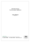
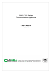
1
CAR-5030 Series Communication Appliance User′′s Manual Revision: 1.0 Portwell Inc. 8th Floor, No. 242, Bo-Ai St., Shu-Lin City, Taipei County 238, Taiwan TEL: +886-2-7705-8888 FAX: +886-2-7731-9988 http://www.portwell.com Table of Contents Chapter 1 Introduction ........................................................................................................... 2 1.1 About This Manual...........................................................................................................2 1.2 Manual Organization .......................................................................................................2 1.3 Technical Support Information .........................................................................................2 1.4 Board Layout ...................................................................................................................3 1.5 System Block Diagram ...................................................................................................4 1.6 Product Specifications ...............................................................................................................5 Chapter 2 Getting Started ............................................................................................. 7 2.1 Included Hardware ........................................................................................................7 2.2 Before You Begin ............................................................................................................7 2.3 Hardware Configuration Setting .......................................................................................8 2.4 The Chassis ..................................................................................................................14 2.5 Open the Chassis ..........................................................................................................14 2.6 Install a Different Processor ...........................................................................................15 2.7 Remove and Install DIMM .............................................................................................18 2.8 Remove and Install Compact Flash Card ......................................................................21 2.9 Remove and Install Battery ............................................................................................21 2.10 Install HDD ....................................................................................................................22 2.11 Ear Mount Kit Installation ..............................................................................................22 2.12 Remove EZIO / LCD .....................................................................................................24 2.13 Remove Power Supply ...................................................................................................26 2.14 Remove main board ......................................................................................................28 2.15 Use a Client Computer ...................................................................................................30 Note: Terminal software may need to update for correct console output. ....................... 30 Chapter 3 BIOS Setting .......................................................................................... 33 3.1 BIOS Setup Information .................................................................................................33 Chapter 4 Appendixes ......................................................................... 5.1 CAR-5030 Ethernet modules configuration ...................................... CAR-5030 Series User’s Manual 1 Chapter 1 Introduction 1.1About This Manual This manual contains all required information for setting up and using the CAR-5030 series. CAR-5030 provides the essential platform for delivering optimal performance and functionality in the value communications appliance market segment. This manual should familiarize you with CAR-5030 operations and functions. CAR-5030 series provide Up to five PCI-E x8 slot support proprietary NIC to serve communication applications like Firewall, requiring ten Ethernet ports to connect external network (internet), demilitarized zone and internal network. CAR-5030 series overview: Supports Dual Sandy Bridge-EP socket R 130W 16 DDR3 1600 RDIMM slots for each CPU Two USB ports and one RJ45 port on COM1. Dual 3.5” SATA/ SAS HDD User-friendly LCD control panel Three PCI-Ex8 and one PCI-Ex4 add-on card slots. Provides absolute high flexibility of customized I/O configuration for front accessible PCI-E modules 1.2 Manual Organization This manual describes how to configure your CAR-5030 system to meet various operating requirements. It is divided into three chapters, with each chapter addressing the basic concept and operation of this system. Chapter 1: Introduction. This section describes how this document is organized. It includes brief guidelines and overview to help find necessary information. Chapter 2: Hardware Configuration Setting and Installation. This chapter demonstrated the hardware assembly procedure, including detailed information. It shows the definitions and locations of Jumpers and Connectors that can be used to configure the system. Chapter 3: Operation Information. This section provides illustrations and information on the system architecture and how to optimize its performance. Chapter 4: This section describes how to programming software. It includes EZIO. 1.3 Technical Support Information Users may find helpful tips or related information on Portwell's web site: http:// www.portwell.com A direct contact to Portwell's technical person is also available. For further support, users may also contact Portwell’s headquarter in Taipei or local distributors. Taipei Office Phone Number: +886-2-7705-8888 CAR-5030 Series User’s Manual 2 1.4Board Layout Figure 1-1 CAR-5030 Series User’s Manual Board Layout of CAR-5030 M/B 3 1.5 System Block Diagram Figure 1-2 CAR-5030 Basic Block Diagram CAR-5030 Series User’s Manual 4 1.6 Feature Product Specifications Detailed Description 1 CPU 2 CPU Board 3 System Memory 16 DDR3 1600 RDIMM slots for each CPU 4 Power Supply 500W/ 600W 1+1 Redundant PSU w/ smart fan 5 Ethernet 6 SATA & IDE Interfaces Dual Sandy Bridge-EP socket R 130W CAPB-5030VR Support ECC, R and U DIMM Dimension: TBD Up to five PCI-E x8 slot support proprietary NIC Dual 3.5” SATA/ SAS HDD EZIO 2 Drawable 3.5” HDD Kit USB interface: dual-USB connectors RS232 interface: RS232 port with RJ45 connector for system console, tab-down, no LED. Dual Mgnt. Ports One IPMI port 7 Front Panel Hardware power on/off Button F/D button Drawable Ethernet module LED: System LED: Power, Data access Ethernet LED: For every Ethernet interface there should be LEDs for link status and speed of LAN-ports, which should be built in the connector. AC power inlet 8 Rear Panel Power switch Two expansion module for PCI-Ex8 9 Dimension 2U Dimension: 438(W) x 626 (D) x 88 (H) (TBD) 11 Environmental requirement Operating Storage Temperature 0°C to 40°C -10°C to 70°C Relative Humidity 20 to 90% RH Acoustics CAR-5030 Series User’s Manual 5 to 95% RH @55℃ (EZIO) 5 Feature Detailed Description w/o EZIO @70℃ Operating Shock 0.5 Sine s ock, 10G peak, 10 +/- 3 ms on (X,Y,Z) axis Vibration 0.5G (Peak) / 5~5 0 Hz, 2hours at ach of Z axis Storage (Packaged) Sine Wave,2.0G/ 5~500 Hz, 2hours at ach axis(X,Y,Z) Transpor ation (Packaged) 0.5 sine shock 50 peak on each surface. Dr p (Packaged) Portwell standard from level 1 to 4 Random Vibration (Packaged) Sine Wave,2.8G/ 5~500 Hz, 1hours at each axis(X,Y,Z) CAR-5030 Series User’s Manual 6 Chapter 2Getting Started This section describes how the hardware installation and system settings should be done. 2.1Included Hardware The following hardware is included in package: CAR-5030 Communication Appliance System Board One null serial port cable 2.2Before You Begin To prevent damage to any system board, it is important to handle it with care. The following measures are generally sufficient to protect your equipment from static electricity discharge: When handling the board, to use a grounded wrist strap designed for static discharge elimination and touch a grounded metal object before removing the board from the antistatic bag. Handle the board by its edges only; do not touch its components, peripheral chips, memory modules or gold contacts. When handling processor chips or memory modules, avoid touching their pins or gold edge fingers. Restore the communications appliance system board and peripherals back into the antistatic bag when they are not in use or not installed in the chassis. Some circuitry on the system board can continue operating even though the power is switched off. Under no circumstances should the Lithium battery cell used to power the real-time clock be allowed to be shorted. The battery cell may heat up under these conditions and present a burn hazard. WARNING! 1. "CAUTION: DANGER OF EXPLOSION IF BATTERY IS INCORRECTLY REPLACED. REPLACE ONLY WITH SAME OR EQUIVALENT TYPE RECOMMENDED BY THE MANUFACTURER. DISCARD USED BATTERIES ACCORDING TO THE MANUFACTURER’S INSTRUCTIONS" 2. This guide is for technically qualified personnel who have experience installing and configuring system boards. Disconnect the system board power supply from its power source before you connect/disconnect cables or install/remove any system board components. Failure to do this can result in personnel injury or equipment damage. 3. Avoid short-circuiting the lithium battery; this can cause it to superheat and cause burns if touched. 4. Do not operate the processor without a thermal solution. Damage to the processor can occur in seconds. 5. Do not block air vents. Minimum 1/2-inch clearance required. CAR-5030 Series User’s Manual 7 2.3Hardware Configuration Setting 2.3.1 CAR-5030 System Board Jumper In general, jumpers on CAR-5030 system board are used to select options for certain features. Some of the jumpers are configurable for system enhancement. The others are for testing purpose only and should not be altered. To select any option, cover the jumper cap over (Short) or remove (NC) it from the jumper pins according to the following instructions. Here NC stands for “Not Connected”. CAR-5030 Series User’s Manual 8 Jumper List JP3: Slot E(J12) PCI express width *1-2: two x8(default), 2-3: by Riser card Open: x16 JP5: Factory test use only *1-2 3-4(default) JP7: CMOS clean *1-2: Normal (default), 2-3: clear JP9: Factory test use only *open (default) JP11: Auto power ON *1-2 enable (default), Open: Disable J76: SATA DOM Power Select *2-3 GND (default), 1-2: VCC JP4: NMI button *open (default) JP6: Factory test use only *Open (default) JP8: GPIO port(J52) power selector *1-2: 5Voltage (default), 2-3: 3.3Voltage JP10: Factory test use only *1-2 3-4(default) JP12: Watchdog timer reset *1-2 enable (default), Open: Disable J78: Mgmt. Board RES/PB Switch *1-2 PB (default), 2-3: RB LED List D2 : (Green) 5VSB indicator, Power standby D3 : (Orange) VCC3 indicator, Power ON Thermal sensor List RT1 : CPU1 PWM temperature sensor RT2 : CPU1 VSA temperature sensor RT3 : CPU0 VSA temperature sensor RT4 : CPU0 PWM temperature sensor RT5 : CPU1 temperature sensor RT6 : System temperature sensor RT7 : CPU0 temperature sensor CAR-5030 Series User’s Manual 9 Connector List J1/ J10/J13/J30/J32/J34/J35/J45: N/A J3: Chassis Fan 2 J5: Power supply SM bus for IPMI J7: ATX PSU main connector J9: AUX +12V input for CPU0 J11: AUX +12V input for CPU1 J14: CPU 1, CH H DIMM1 J16: CPU 1, CH G DIMM1 J18: CPU 0, CH D DIMM1 J20: CPU 0, CH C DIMM1 J22: CPU 1, CH E DIMM0 J24: CPU 1, CH F DIMM0 J26: CPU 0, CH A DIMM0 J28: CPU 0, CH B DIMM0 J31: PS2 Keyboard / Mouse J36: CPU 1(left) FAN J38: IPMI J40: SATA port 0 (6 Gb/s) J42: IPMB J44: COM 2 (for Ezio)* J47: SAS port 1 J49: COM 2 J51: LPC debug port* J53: Over Temperature LED connector J55: TPM J57: USB 2/3 (aux USB)* J59: Front Fan J61: Front Fan J63: Front Fan J65: PCI express x8 slot B (CPU 0)* J67 ~ J73/J75: N/A J2: Chassis Fan 1 J4: Host SM bus J6: PM bus connector J8: Chassis Fan 3 J12: PCIe expansion x16 slot E J15: CPU 1, CH H DIMM0 J17: CPU 1, CH G DIMM0 J19: CPU 0, CH D DIMM0 J21: CPU 0, CH C DIMM0 J23: CPU 1, CH E DIMM1 J25: CPU 1, CH F DIMM1 J27: CPU 0, CH A DIMM1 J29: CPU 0, CH B DIMM1 J33: CPU 0 (right) FAN J37: Cable PCI express x8* J39: PCI express slot D x8 + x4* J41: SATA port 1 (6 Gb/s) J43: CF socket J46: SATA port 4 (SATA DOM only) J48: SAS port 0 J50: Cable PCI express x8 J52: GPIO* J54: VGA* J56: System Management Link J58: CASEOPEN J60: Front Fan J62: Front Panel Control J64: PCI express x8 slot A (CPU 1)* J66: PCI express x8 slot C (CPU 0)* J74: Expansion slot M ABM-5020 manager board connector U29: CPU 1 socket U30: CPU 0 socket *With detail pin list J49: COM 2 9 7 5 3 1 10 8 6 4 2 9 GND 10NC 7 DTR 5 TXD 3 RXD 1 CD 8 RI 6 CTS 4 RTS 2 DSR 7 GP34 8 GP23 5 GP35 6 GP22 3 GP36 4 GP31 1 GP37 2 GP30 5 GND 6 GND 3 NP 4 NP 1 MOUSE DATA 2 KEY DATA J52: GPIO 9 7 5 3 1 10 8 6 4 2 9 GND 10 POWER J31: PS/2 KEYBOARD MOUSE 9 7 5 3 1 10 8 6 4 2 9 MOUSE CLK 10 KEY CLK 7 VCC(+5V) 8 VCC(+5V) CAR-5030 Series User’s Manual 10 J57: USB 2(3) 9 7 5 3 1 10 8 6 4 2 9 SBV3 (+5V) 10 NC 7 SBD-3 8 GND J62: Front Panel Control 4 PWR 2 PWR LED+ LED 1 IDE 3 IDE LED+ LED- 5 SBD+3 6 SBD+2 3 GND 4 SBD-2 6 8 PWR ON+ 10 LDFPWRON5 RESET- 7RESET+ 9 LDF+ 1 NC 2 SBV2 (+5V) 12 FAULT LED+ 11 CHASSIS LED+ 14 FAULT LED13 CHASSIS LED- J51: LPC debug port 2 4 6 8 10 1 3 5 7 9 2 VCC3 1 LAD0 4 RESET# 3 LAD1 6 LFRAME# 5 LAD2 7 V-SYNC 8 GND 5 BLUE 6 DDC_DATA 4 N/A 3 RXD 6 N/A 5 TXD 8 33MHZ CLOCK 10 GND 7 LAD3 J54: VGA 9 7 5 3 1 10 8 6 4 2 9 H-SYNC 10NC 3 GREEN 4 GND 1 RED 2 DDC_CLOCK J44: EZ-IO (COM 2) 2 4 6 8 10 1 3 5 7 9 2 N/A 1 GND 8 N/A 75V 10 N/A 9 N/A J64/J65/J66: PCI express x8(or x4 2pcs) expansion slot pin define B1 +12V A1 VCC B2 +12V A2 +12V B3 +12V A3 +12V B4 GND A4 SLOT ID BIT0 B5 SMB_CLOCK A5 VCC B6 SMB_DATA A6 VCC B7 GND A7 VCC3 B8 3.3V A8 VCC3 B9 SLOT ID BIT1 A9 VCC3 B10 3.3V DUAL A10 VCC3 B11 WAKE- A11 PERST- B12 PWRGD- A12 GND B13 GND A13 REFCLK+1 B14 PET+0 A14 REFCLK-1 B15 PET-0 A15 GND B16 GND A16 PER+0 B17 RSVD A17 PER-0 B18 GND A18 GND B19 PET+1 A19 RSVD CAR-5030 Series User’s Manual 11 B20 PET-1 A20 GND B21 GND A21 PER+1 B22 GND A22 PER-1 B23 PET+2 A23 GND B24 PET-2 A24 GND B25 GND A25 PER+2 B26 GND A26 PER-2 B27 PET+3 A27 GND B28 PET-3 A28 GND B29 GND A29 PER+3 B30 REFCLK+0 A30 PER-3 B31 REFCLK-0 A31 GND B32 GND A32 RSVD B33 PET+4 A33 RSVD B34 PET-4 A34 GND B35 GND A35 PER+4 B36 GND A36 PER-4 B37 PET+5 A37 GND B38 PET-5 A38 GND B39 GND A39 PER+5 B40 GND A40 PER-5 B41 PET+6 A41 GND B42 PET-6 A42 GND B43 GND A43 PER+6 B44 GND A44 PER-6 B45 PET+7 A45 GND B46 PET-7 A46 GND B47 GND A47 PER+7 B48 PE_WIDTH0- (L: x8, H: x4) A48 PER-7 B49 GND A49 GND *J64: SLOT A ID BIT 0/1 equal 00** J65: SLOT B ID BIT 0/1 equal 01 ** *J66: SLOT C ID BIT 0/1 equal 10 CAR-5030 Series User’s Manual 12 J37/J50 PCI express cable x8 pin define A1 GND B1 GND A2 PET+0 B2 PER+0 A3 PET-0 B3 PER-0 A4 GND B4 GND A5 PET+1 B5 PER+1 A6 PET-1 B6 PER-1 A7 GND B7 GND A8 PET+2 B8 PER+2 A9 PET-2 B9 PER-2 A10 GND B10 GND A11 PET+3 B11 PER+3 A12 PET-3 B12 PER-3 A13 GND B13 GND A14 REFCLK+ B14 3.3V A15 REFCLK- B15 3.3V A16 GND B16 3.3V A17 SMB_CLOCK B17 GND A18 SMB_DATA B18 GND A19 GND B19 GND A20 CPRSNT# B20 PWRGD# A21 PE_WIDTH0- (L: x8, H: x4) B21 RESET# A22 GND B22 GND A23 PET+4 B23 PER+4 A24 PET-4 B24 PER-4 A25 GND B25 GND A26 PET+5 B26 PER+5 A27 PET-5 B27 PER-5 A28 GND B28 GND A29 PET+6 B29 PER+6 A30 PET-6 B30 PER-6 A31 GND B31 GND A32 PET+7 B32 PER+7 A33 PET-7 B33 PER-7 GND B34 GND A34 CAR-5030 Series User’s Manual 13 2.4The Chassis The system is integrated in a customized 2U chassis (Fig. 2-1, Fig. 2-2). On the front panel user will find a 4-push-button LCD module (EZIO), two USB ports and a COM port and Ethernet ports. CAR-5030 Fig. 2-1 Front view of the chassis Fig. 2-2 Rear view of the chassis 2.5Open the Chassis 1.Please loosen the screw of top cover: two at the left and right side, last one at the rear side, to remove the top lead (Fig. 2-3). Fig. 2-3 Take off screws 2.The top lead (Fig. 2-4) can be removed from the base stand (Fig. 2-5). CAR-5030 Series User’s Manual 14 Fig. 2-4 The top lead Fig. 2-5 The base stand 2.6Install a Different Processor To install a CPU 1. Local the CPU socket on the motherboard CAR-5030 CPU socket B ILM 2. Press the load lever with your thumb (A), then move it to left (B) until it is released from the retention tab 3. Lift the load lever in the direction of the arrow to a 135° angle CAR-5030 Series User’s Manual 15 4. Lift the load plate with your thumb and forefinger to a 100° angle (A), then push the PnP cap from the load plate window to remove (B) 5. Position the CPU over the socket, making sure that the gold triangle is on the bottom-left corner of the socket. The socket alignment key should fit into the CPU notch 6. Close the load plate (A), then push the load lever (B) until it snaps into the retention tab CAR-5030 Series User’s Manual 16 Configure Processor Speed The system was designed to self-detect its CPU speed. So it does not require any system adjustment. Once the system CPU does not run frequency correctly, try to clean CMOS or enter BIOS setup to load failsafe default then load optimal default one time. CAR-5030 Series User’s Manual 17 2.7Remove and Install DIMM Follow these steps to upgrade RAM module: 1. Unlock a DIMM socket by pressing the retaining clips outward 2. Align a DIMM on the socket such that the notch on the DIMM matches the break on the socket 3. Firmly insert the DIMM into the socket until the retaining clips snap back in place and the DIMM is properly seated CAR-5030 Series User’s Manual 18 Follow these steps to remove a DIMM: 1. Simultaneously press the retaining clips outward to unlock the DIMM 2. Remove the DIMM from the socket Follow these steps for DIMM configuration: 1. Memory socket A0 ~D1 are controlled by CPU0 2. Memory socket E0 ~H1 are controlled by CPU1 3. If users use only CPU0, memory can’t be used when installed on socket A0~D1 4. When user installs memory, please install them from A0, B0, C0, D0, E0, F0, G0 or H0 first. (Black socket) 5. Memory speed support depends on the types of CPU. CPU1 CAR-5030 Series User’s Manual CPU0 19 6. Follow the table below for memory installation: For Nehalem/Westmere CPU. Memory optimal performance for main board with CPU 0 installed. Branch 0 Branch 1 2 DIMM A0 B0 4 DIMM A0 B0 8 DIMM A0 A1 Branch 2 Branch 3 D0 B0 B1 D1 C0 D0 C1 C0 Memory optimal performance for main board with CPU 1 installed. Branch 0 Branch 1 2 DIMM E0 F0 4 DIMM E0 F0 8 DIMM E0 E1 Branch 2 Branch 3 H0 F0 F1 H1 G0 H0 G1 G0 Memory optimal performance for main board with two CPUs installed CPU0 Branch 0 Branch 1 8DIMM A0 B0 16 DIMM A0 A1 B0 CPU1 Branch 2 Branch 3 D0 B1 D1 D0 C1 Branch 0 Branch 1 C0 E0 F0 C0 E0 E1 F0 Branch 2 Branch 3 H0 F1 H1 H0 G0 G1 G0 Memory speed support table Speed (MHz) CPU0 Branch 0 Branch 1 800,1066 1333 A0 B0 800,1066 A0 A1 B0 CAR-5030 Series User’s Manual CPU1 Branch 2 Branch 3 D0 B1 D1 D0 C1 Branch 0 Branch 1 C0 E0 F0 C0 E0 E1 F0 Branch 2 Branch 3 H0 F1 H1 H0 G0 G1 G0 20 2.8Remove and Install Compact Flash Card 1. Insert the Compact Flash Card (Fig. 2-7) into the CF interface (Fig. 2-8). Fig. 2-6 Compact Flash Card Fig. 2-7 Insert Compact Flash Card into the CF interface 2.The completed installation of Compact Flash Card is shown as Fig. 2-8 Fig. 2-8 Completion of Compact Flash Card 2.9Remove and Install Battery 1. Press the metal clip back to eject the button battery (Fig. 2-9). 2. Replace it with a new one by pressing the battery with fingertip to restore the battery (Fig. 2-10). Fig. 2-9 Eject the battery CAR-5030 Series User’s Manual Fig. 2-10 Restore the battery 21 2.10Install HDD The system has an internal drive bay for one 3.5" SATA hard disk drive. If the HDD is not preinstalled, user can install it by himself. Follow the steps below to install the HDD: 1. Fasten the four screws to lock HDD and bracket together (Fig. 2-11a, 2-11b). Fig. 2-11a A 3.5”SATA HDD and the HDD bracket Fig. 2-11b Fix HDD to the bracket 2. Install HDD tray to CAR-5030 system (Fig. 2-12). Fig. 2-12a Connect HDD bracket to CAR-5030 Fig. 2-12b Fix HDD into CAR-5030 system system then push the switch in. 2.11Ear Mount Kit Installation The CAR-5030 series shipped with 2 ear mount kits. The following is the installation instruction of these ear mounts: 1. Take out the L shape ear mount kits. One ear mount fits on one side of the chassis, 2. Placing the side with four holes agonists the chassis and the side with two holes face outward. (Fig. 2-13.1) 3. If users need to mount system from front. Fasten five screws on each side (Fig. 2-13.1). And push the system from front into rack mount. CAR-5030 Series User’s Manual 22 Fig.2-13.1 Fasten the screws to the side 4. If users need to mount system from rear. Fasten nine screws on each side (Fig. 2-13.2 and Fig. 2-13.3). And push the system from rear into rack mount. Fig.2-13.2 Fasten the screws to the side CAR-5030 Series User’s Manual Fig.2-13.3 Fasten the screws to the side 23 2.12Remove EZIO / LCD The CAR-5030 series support EZIO modules. The following is the remove instruction of these EZIO/LCD modules: 1. Remove all cables from EZIO (Fig. 2-14, 2-15, 2-16). Fig.2-14 Remove the EZIO cable from EZIO Fig.2-15 Cut the cable collector. Fig.2-16 Remove the front panel cable from main board CAR-5030 Series User’s Manual 24 2. Remove the front panel from chassis. (Fig. 2-17a, 2-17b). Fig.2-17a Please loosen the screw of top cover: two at the left and right side, last one at the rear side, to remove the top lead Fig.2-17b Remove screws and rack. 3. Remove the EZIO kit from chassis. Fig.2-18 Remove the screws from EZIO kit 4. Final remove the EZIO/LCD module. Fig.2-20 Remove EZIO/LCD from EZIO kit CAR-5030 Series User’s Manual 25 2.13Remove Power Supply The following is the remove step instruction of power supply. 1. Remove the power modules Fig.2-21.1 Remove the screw to unlock the power module. Fig.2-21.2 Pull out the power modules. 2. Remove all power cables from main board and HDD bay. Remove I2C cable from board. Fig.2-23 Remove all power cables from board and HDD Fig.2-24 Remove all cables from the board. bay. Fig.2-23 Remove I2C cable. CAR-5030 Series User’s Manual 26 3. Remove all screws from power supply. Fig.2-25.1 Remove the screws. Fig.2-25.2 Remove the screws. 4. Push the power supply inside system then lift up power supply to pull out the power supply. Fig.2-26.1 Push the power supply into system first. CAR-5030 Series User’s Manual Fig.2-26.2 Lift up and Pull out the power supply. 27 2.14Remove main board The section shows how to remove the main board. 1. Remove all add-on modules or LOM devices from system first. Fig.2-27 Remove all add-on modules. 1. Fig.2-28 1.Remove the screws. 2. .Remove the LOM from the socket. 2. Remove following items from main board: cables, CPU cooler, CPU, memory. Fig.2-29 Remove CPU cooler, CPU and memory. All SATA and power cble. Fig.2-30 Remove all fan cable from board. 3. After remove above items, and push the PnP cap back to CPU socket. Users can start remove all screws from board. CAR-5030 Series User’s Manual 28 Fig.2-31 Remove all screws from main board. P.S After remove all screws from board. User can remove main board. Please be genteelly and carefully. Avoid colliding board with chassis bottom sticks. It may damage the main components. CAR-5030 Series User’s Manual 29 2.15Use a Client Computer Connection Using Hyper Terminal To access CAR-5030 via the console, Hyper Terminal is one of many choices. Follow the steps below for the setup: Fig.2-36 Connect null serial port cable to CAR-5030 console management port. Note: Terminal software may need to update for correct console output. 1. Execute HyperTerminal under C:\Program Files\Accessories\HyperTerminal 2. Enter a name to create new dial CAR-5030 Series User’s Manual 30 3. For the connection settings, make it Direct to Com1. 4. Please make the port settings to Baud rate 19200, Parity None, Data bits 8, Stop bits 1 5. Turn on the power of CAR-5030 system, after following screen was shown: CAR-5030 Series User’s Manual 31 6. User can see the boot up information of CAR-5030. 7. When message “Hit <DEL> if user want to run Setup” appear during POST, after turning on or rebooting the computer, press <Tab> key immediately to enter BIOS setup program. This is the end of this section. If the terminal did not port correctly, please check the previous steps. CAR-5030 Series User’s Manual 32 Chapter 3 BIOS Setting 3.1 BIOS Setup Information Power on the system, press the <Del> to run BIOS setup (remote mode is <Tab>). After you press the <Delete> key, the main BIOS setup menu displays. You can access the other setup screens from the main BIOS setup menu, such as the Chipset and Power menus. The BIOS setup/utility uses a key-based navigation system called hot keys. Most of the BIOS setup utility hot keys can be used at any time during the setup navigation process. These keys include <F1>, <F4> <Enter>, <ESC>, <Arrow> keys, and so on. Control Keys Key ↑↓Up /Down Left/Right +Plus/ Minus Function The Up and Down <Arrow> keys allow user to select a setup item or subscreen. The Left and Right <Arrow> keys allow user to select a setup screen. For example: Main screen, Advanced screen, Chipset screen, and so on. The Plus and Minus <Arrow> keys allow user to change the field value of a particular setup item. For example: Date and Time. CAR-5030 Series User’s Manual 33 CAR-5030 Series User’s Manual 34 Main Menu When user enters the Setup Utility, user see the Main setup screen. User can always return to the Main setup screen by selecting the Main tab. There are two Main Setup options. They are described in this section. System Date / Time Use this option to change the system time and date. Highlight System Time or System Date using the <Arrow> keys. Enter new values through the keyboard. Press the <Tab> key or the <Arrow> keys to move between fields. The date must be entered in MM/DD/YY format. The time is entered in HH:MM:SS format. CAR-5030 Series User’s Manual 35 Advanced BIOS Setup Select the Advanced tab from the setup screen to enter the Advanced BIOS Setup screen. You can select any of the items in the left frame of the screen, such as SuperIO Configuration, to go to the sub menu for that item. You can display an Advanced BIOS Setup option by highlighting it using the <Arrow> keys. All Advanced BIOS Setup options are described in this section. The Advanced BIOS Setup screen is shown below. The sub menus are described on the following pages. IDE Configuration Setup From the IDE Configuration screen, press <Enter> to access the sub menu. Use the up and down <Arrow> keys to select an item. The settings are described on the following pages. CAR-5030 Series User’s Manual 36 SUPER IO CONFIGURATION You can use this screen to select options for the Super I/O settings. Use the up and down <Arrow> keys to select an item. Use the <Plus> and <Minus> keys to change the value of the selected option. The settings are described on the following pages. The screen is shown below. REMOTE ACCESS CONFIGURATION Remote Access Configuration You can use this screen to select options for the Remote Access Configuration. Use the up and down <Arrow> keys to select an item. Use the <Plus> and <Minus> keys to change the value of the selected option. The settings are described on the following pages. The screen is shown below Remote Access You can disable or enable the BIOS remote access feature here. CAR-5030 Series User’s Manual 37 Serial Port Number Select the serial port you want to use for console redirection. You can set the value for this option to either COM1. USB Configuration You can use this screen to select options for the USB Configuration. Use the up and down<Arrow> keys to select an item. Use the <Plus> and <Minus> keys to change the value of the selected option. The settings are described on the following pages. The screen is shown below. Legacy USB Support Legacy USB Support refers to the USB mouse and USB keyboard support. Normally if this option is not enabled, any attached USB mouse or USB keyboard will not become available until a USB compatible operating system is fully booted with all USB drivers loaded. When this option is enabled, any attached USB mouse or USB keyboard can control the system even when there is no USB drivers loaded on the system. Set this value to enable or disable the Legacy USB Support. The Optimal and Fail-Safe default setting is Disabled. CAR-5030 Series User’s Manual 38 CPU Configuration You can use this screen to select options for the CPU Configuration. Use the up and down<Arrow> keys to select an item. Use the <Plus> and <Minus> keys to change the value of the selected option. Note: The CPU Configuration setup screen varies depending on the installed processor. Boot Settings Select the Boot tab from the setup screen to enter the Boot BIOS Setup screen. CAR-5030 Series User’s Manual 39 BOOT DEVICE PRIORITY Use this screen to specify the order in which the system checks for the device to boot from. To access this screen, select Boot Device Priority on the Boot Setup screen and press<Enter>. The following screen displays: Exit Menu Select the Exit tab from the setup screen to enter the Exit BIOS Setup screen. You can display an Exit BIOS Setup option by highlighting it using the <Arrow> keys. All Exit BIOS Setup options are described in this section. The Exit BIOS Setup screen is shown below. Saving Changes and Exit When you have completed the system configuration changes, select this option to leave CAR-5030 Series User’s Manual 40 Setup and reboot the computer so the new system configuration parameters can take effect. Select Exit Saving Changes from the Exit menu and press <Enter>. Discard Changes and Exit Select this option to quit Setup without making any permanent changes to the system configuration. Select Exit Discarding Changes from the Exit menu and press <Enter>. Saving Changes and Exit Reset the system after saving the changes. Discard Changes and Reset Reset system setup without saving any changes. Save Changes Save changes done so far to any of the setup options. Discard Changes Discard Changes done so far to any of the setup options. Restore Defaults Restore/Load Default values for all the setup options. Save as User Defaults Save the changes done so far as User Defaults. Restore User Defaults Restore the User Defaults to all the setup options. CAR-5030 Series User’s Manual 41