1
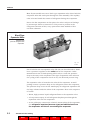
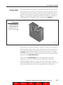
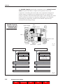
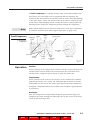
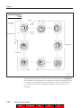
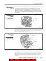
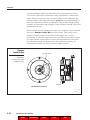
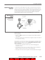
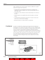
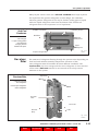
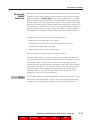
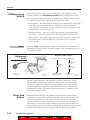
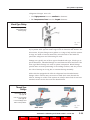
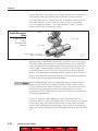
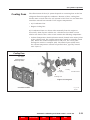
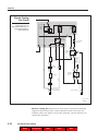
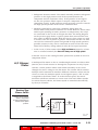
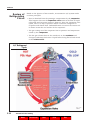
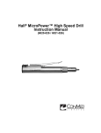
Section 3
A/C System Components
In the previous sections, we referred to the functions of the A/C
components. Here’s how each one works in closer detail.
A/C System
Components
Evaporator
Expansion
Valve
Receiver-Drier*
Condenser
Expansion
Valve
Compressor
Fig. 3-1
752f301
The expansion valve receives liquid refrigerant from the high-pressure
components (compressor and receiver/drier). In order for the system to
develop pressure, the flow of refrigerant must be met with a restriction.
The expansion valve provides the needed restriction in the system. It
creates the difference between the high-pressure side of the system and
the low-pressure side.
Capillary Tube
Traditional
Expansion Valve
Controls amount of
refrigerant into
evaporator core.
*Built into
sub-cool condenser
on some models
Diaphragm
Chamber
Equalizer Circuit
(for Internal Equalizer
Type)
Diaphragm
HeatSensing
Tube
Valve
Outlet
Inlet
Pressure
Spring
Fig. 3-2
752f302
TOYOTA Air Conditioning and Climate Control – Course 752
Home
Bookmarks
Next
Print
Exit
3-1
Section 3
Most Toyota models now use a block-type expansion valve where both the
evaporator inlet and outlet pass through the valve assembly. The capillary
tube is located inside the stream of refrigerant leaving the evaporator.
Due to the low temperature at this point, the valve is subject to blockage
by microscopic debris or internal ice if any water is present in the
refrigerant. Because of this, every system has some method to filter
out these elements.
Block-Type
Expansion Valve
Releases high
pressure refrigerant into
evaporator.
Valve
Fig. 3-3
752f303
Not all vehicles use an expansion valve like the one described above. Some
have a pressure-regulator at the outlet end of the evaporator. Other
manufacturers use a fixed-opening orifice tube to create the pressure
drop at the entry to the evaporator. This type of expansion valve relies on
the cycling of the compressor clutch to vary the flow and prevent icing.
The expansion valve is located at the inlet of the evaporator. A small
passage creates a pressure drop as the refrigerant enters the evaporator.
The pressure drop occurs as the small spray of refrigerant expands to fill
the large volume inside the tubes of the evaporator. Here is the sequence
of events:
• Warm, high-pressure liquid refrigerant flows to the expansion valve
• A low-pressure spray of cold refrigerant droplets pass through the
expansion valve into the evaporator
• As the cold spray contacts the relatively warm tubing of the evaporator,
the refrigerant vaporizes (becomes a gas) and absorbs heat from
the evaporator and the air surrounding the evaporator
3-2
TOYOTA Technical Training
Home
Bookmarks
Next
Print
Exit
A/C System Components
Evaporator
The action between the expansion valve and the evaporator is the key to
heat transfer in the system. The evaporator is the heat exchanger for the
low-pressure side of the system. It is the key heat exchanger in the A/C
system. All incoming or recirculated air passes through the evaporator. In
doing so, the evaporator absorbs heat from the cabin air (car interior) or
incoming fresh air so this heat can be carried to the condenser.
Evaporator
• Removes heat from
interior as refrigerant is
released into the core.
• Dehumidifies air by condensing moisture on the
fins.
Fig. 3-4
752f304
Evaporators are typically multiple-flow designs and made from aluminum.
Since the surface fins or plates of the evaporator are usually colder than
the air flowing past them, any moisture (water vapor) in the air tends to
condense and form liquid droplets on the fins. The moisture eventually
drains from the evaporator case through a drain hose to the ground. This
process is called dehumidification.
This process of dehumidifying is not only important to passenger
comfort, but can also be used in cold or humid climates to reduce
windshield fogging. However, a large amount of heat must be removed
from water vapor in order to condense it, so extreme humidity reduces the
ability of the evaporator to lower the temperature of the incoming air.
TOYOTA Air Conditioning and Climate Control – Course 752
Home
Bookmarks
Next
Print
Exit
3-3
Section 3
Expansion
Valve/
Evaporator
Interaction
Since the evaporator surface temperature can be close to 32° F (0° C),
there could be a problem in high humidity conditions when moisture
vapor condenses on the evaporator and freezes. This frozen water forms
an insulating layer that prevents air from reaching the evaporator to
exchange heat.
In order to prevent icing, the expansion valve can change the size of
the spray orifice (opening). The size of the orifice is controlled by a
spring-loaded diaphragm that moves according to a heat-sensing tube
(bulb). This bulb, called the capillary tube is located at the outlet of the
evaporator. A thin, hollow tube connects the sensing tube to the
diaphragm chamber. The sensing tube contains refrigerant and senses the
evaporator temperature which changes the pressure inside the tube. The
capillary tube transfers this pressure to the diaphragm to push against
the spring and open the expansion valve to control refrigerant flow to the
evaporator. Less flow = less heat transfer; more flow = more heat transfer.
For example, if there is a high heat load in the vehicle, the evaporator
temperature will be relatively high (more heat transfer). The refrigerant
in the sensing tube will therefore expand and the increased pressure will
tend to open the expansion valve more. This increases refrigerant flow
and heat transfer in the evaporator. When the system stabilizes, the
evaporator surface temperature should remain constant at about
32° F (0° C) in order to provide the greatest heat-removing capacity.
The traditional expansion valve has external equalization. The block-type
expansion valve is internally vented. This helps prevent flooding the
evaporator during operation with a high heat load.
Compressor
The compressor is driven by a drive belt and is a type of pump which
moves a compressible gas, as opposed to a pump that moves a liquid
(e.g. water pump). The air compressor in your repair shop and the intake
and compression strokes in a 4-stroke cycle engine are two other examples
of compressors.
In order for the refrigerant to exchange heat at the condenser, it must be
hotter than the air outside the vehicle. The compressor accomplishes this
by raising the pressure, and therefore, the temperature of the refrigerant.
3-4
TOYOTA Technical Training
Home
Bookmarks
Next
Print
Exit
A/C System Components
An important difference between a compressor and a pump is that a
compressor cannot pump liquids. Since liquids cannot be compressed,
a compressor filled with liquid will either lock up or break depending on
the amount of torque applied to its pulley by the engine crankshaft. More
commonly, the reed valve assembly that controls gas flow inside will be
destroyed when a compressor hydraulically locks.
Most compressors have a “bolt-on” fitting block to provide connections to
the low-pressure side of the system (suction side) and high-pressure side
of the system (discharge port). There may also be fittings on or near the
compressor to connect pressure gauges.
Reed Valve
Control of
Refrigerant Flow
Discharge Reed Valve
Reed valves control
both suction and
discharge flow.
Discharge Reed Valve
Fig. 3-5
Suction Reed Valve
752f305
Various Toyota vehicles use or have used one of the following types of A/C
compressors:
•
Piston
•
Through-Vane
•
Swash-plate
•
Variable Capacity
•
Scroll-type
Piston-type compressors have valves to control the flow of intake and
exhaust gases. For simplicity, A/C compressors use spring-tensioned
stainless steel reed valves which allow gas flow in one direction and only
when a significant pressure difference exists between the chamber of the
compressor and the intake or outlet passages. The earliest compressors
were belt-driven using two- or three-pistons with connecting rods and a
TOYOTA Air Conditioning and Climate Control – Course 752
Home
Bookmarks
Next
Print
Exit
3-5
Section 3
crankshaft supported by ball bearings. Lubrication is provided by a
splash from a sump in the compressor base. Construction of reciprocating
compressors are very similar to a four-stroke cycle lawn mower engine.
Discharge
Suction
Piston-type A/C
Compressor
Reed Valve Construction.
Down-Stroke
Up-Stroke
Fig. 3-6
752f306
Through-Vane (TV) compressors replaced reciprocating, piston-type
compressors. Through-vane compressors reduce rotating mass by
eliminating pistons in favor of sliding vanes which seal against the
compressor housing at both ends. These compressors are lubricated by
oil from a pressurized chamber in the rear of the compressor.
Discharge Reed Valve
Through-Vane
Compressor
Discharge Valve
Exhaust Port
Rotor
Sludging Valve
Vane
Through-Vane
Rotor Housing
Intake Port
Fig. 3-7
752f307
With four pulses per revolution, TV compressors provide high efficiency
and minimal vibration. However, unlike conventional compressors that
build pressure against a reed valve until it opens, TV compressors
perform compression internally. Because of this, they tend to run hotter
than conventional compressor designs. In addition, for this reason, they
are equipped with an internal pressure release called a sludging valve.
3-6
TOYOTA Technical Training
Home
Bookmarks
Next
Print
Exit
A/C System Components
This valve prevents damaging the through-vanes or the reed valve (which
should “see” only refrigerant gas) by allowing liquid oil to escape from the
compression area into an oil chamber.
Some Toyota vehicles use a swash-plate (also called “wobble plate”) type
compressor. Some models use multiple, opposed pistons arranged around
a single swash-plate with two compression chambers for each cylinder.
The cylinders connect to reed valves and common inlet and outlet passages
at each end. The swash-plate converts the rotary motion of the shaft into
smooth back and forth motions of the pistons. This design provides
reduced vibration and allows more pulses per revolution than a two-piston
reciprocating compressor.
TOYOTA Air Conditioning and Climate Control – Course 752
Home
Bookmarks
Next
Print
Exit
3-7
Section 3
The Variable Capacity swash-plate compressor uses a solenoid control
valve that opens and closes to adjust the low-pressure inlet to the
compressor. Controlling the suction side of the compressor changes the
volume capacity according to the cooling load of the A/C system. This
change in pressure affects the swash-plate angle. It also changes the piston
stroke and thus the amount of refrigerant discharged to the condenser.
Controlling the compressor volume in this manner improves A/C
performance and energy savings.
Variable Capacity
Compressor and
Solenoid Valve
Shoe
Crank Chamber
Piston
Variable stroke of pistons.
Shaft
Solenoid Control
Valve
Piston
Lug Plate
Swash-Plate
Heat Load: Large
Fig. 3-8
Cylinder
752f308
Heat Load: Small
Solenoid Control Valve
Solenoid Control Valve
Low Pressure: High
Low Pressure: Low
Internal Pressure of
Swash-Plate
Chamber: Low
Internal Pressure of
Swash-Plate
Chamber: High
Swash-Plate Angle: Large
Swash-Plate Angle: Small
Piston Stroke: Large
Piston Stroke: Small
Cooling Performance: Large
Cooling Performance: Small
Fig. 3-9
752f309
3-8
TOYOTA Technical Training
Home
Bookmarks
Next
Print
Exit
A/C System Components
A Scroll Compressor is a spirally wound, fixed scroll and variable scroll
that form a pair. The fixed scroll is integrated with the housing. The
rotation of the shaft causes the variable scroll to rotate while maintaining
in the same space. Thus, the volume of the space that is created by both
scrolls varies. This changing volume creates the suction, compression and
discharge forces needed for refrigerant gas flow through the compressor.
Some hybrid models use an electrical motor drive scroll-type compressor
to continue operation even when engine stops (refer to page 3-10).
Note:
Scroll Compressor
Scroll-type A/C
Compressor
Shaft
Magnetic
Clutch
Intake
Port
Oil Separator
Discharge
Port
Pins
Variable
Scroll
Fixed
Scroll
Fixed Scroll
Discharge
Port
Fig. 3-10
752f310
Operation
Suction:
As the capacity of the compression chamber which is created between the
variable scroll and the fixed scroll increases with the revolution of the
variable scroll, refrigerant gas is drawn in from the intake port.
Compression:
As the variable scroll revolves, the capacity of the compression chamber
gradually decreases. As a result, the refrigerant gases drawn in become
compressed and are sent to the center of the fixed scroll. The refrigerant is
completely compressed when the variable scroll completes approximately
2 revolutions.
Discharge:
After the refrigerant is compressed (refrigerant gas pressure high), the
refrigerant gas exits through the discharge port in the center of the fixed
scroll via the discharge valve.
TOYOTA Air Conditioning and Climate Control – Course 752
Home
Bookmarks
Next
Print
Exit
3-9
Section 3
Scroll Compressor
Cycle
Suction
Discharge
Port
Intake
Port
Fixed
Scroll
Variable Scroll
Compression
Discharge
Fig. 3-11
752f311
Some scroll compressors in Toyota vehicles contain a built-in oil separator.
This chamber helps separate the compressor oil from the refrigerant that
circulates in the refrigeration system. Excess oil in the scroll section of
the compressor can lower compressor efficiency and in some cases,
damage it.
3-10
TOYOTA Technical Training
Home
Bookmarks
Next
Print
Exit
A/C System Components
Compressor
Clutch
A drive belt from the crankshaft pulley drives the compressor. Some
systems use V-belts and some use a flat, multirib belt to help reduce
frictional loss and noise. On some models, a single serpentine V-belt
drives all the engine accessories including the A/C compressor. In this
kind of system, an automatic tensioner maintains the correct serpentine
belt tension.
Idler Pulley
Serpentine Belt
System
Some models have
a single belt that drives
multiple components.
A/C
Compressor
Pulley
Fig. 3-12
Crankshaft Pulley
752f312
The compressor clutch engages and disengages the compressor as needed.
With the clutch disengaged (not energized), there is no refrigerant flow
and the compressor pulley spins freely.
Compressor
Clutch
Stator Coil
Engages compressor by
electromagnetic action.
Rotor
Shim
Bearing
Pressure Plate
Fig. 3-13
752f313
The single-plate clutch has an electromagnetic pressure plate to allow
the compressor pulley to freewheel or drive the compressor as conditions
demand. The clutch is normally disengaged. When a relay is energized,
the electromagnetic coil pulls the spring-loaded pressure plate into
the clutch.
TOYOTA Air Conditioning and Climate Control – Course 752
Home
Bookmarks
Next
Print
Exit
3-11
Section 3
The electromagnet allows A/C operation to be controlled by an electric
circuit. The compressor clutch relay is also controlled by a temperature
signal from the evaporator and a pressure switch in the refrigerant line.
In most systems, the compressor clutch cycles ON and OFF periodically to
allow the evaporator to warm up (defrost) during periods of high cooling
demand. An evaporator cold enough to freeze moisture around it does not
transfer heat as well.
Some variable capacity compressors don’t use a magnetic clutch. Instead
they use a Damper Limiter (DL)-type drive pulley. This pulley uses a
damper to absorb torque fluctuations of the engine and a limiter
mechanism. In case the compressor locks, the limiter mechanism causes
the spoke portion of the pulley to break. This separates the pulley from
the compressor shaft and prevents the drive belt from breaking. To
reduce pulley weight, the pulley portion is made of plastic.
Damper
Limiter Pulley
Spoke Portion
• Absorbs torque
fluctuations.
• Protects drive belt if
compressor locks.
Damper
Limiter Mechanism
Fig. 3-14
752f314
3-12
TOYOTA Technical Training
Home
Bookmarks
Next
Print
Exit
A/C System Components
Belt Protection
Sensor
To reduce the overall length of the engine, accessories may be driven by
just one or two belts. The A/C compressor and power steering pump are
usually driven by the same belt. However, if the compressor were to seize,
the belt could break which would cause a loss of power steering assist.
A belt protection system is used on all Toyota models to reduce the
potential safety hazard of a loss of power steering.
Belt Protection
Sensor
Lock Sensor
• Signals ECU that
compressor is locking.
• See text below.
Coil
Pulse Plate
O-Ring
Magnet
Front Shaft
Fig. 3-15
752f315
The belt protection circuit of the A/C amplifier or ECU monitors the
following signals:
• Engine rpm (Ne) is monitored at the Engine Control Module (ECM) or
at the ignitor.
• Compressor shaft rpm is measured by a magnetic pickup in the side of
the compressor housing.
The amplifier or A/C ECU will compare these signals to determine if Ne is
different from the compressor rpm by more than 60 percent for more
than 0.6 seconds. If it does, the system will:
• De-energize the compressor clutch relay. This will disengage the
compressor clutch.
• The amplifier will also cause the indicator lamp in the A/C button or
display to flash (to alert the driver of the malfunction).
• The system will reset when the ignition is switched OFF then ON again.
TOYOTA Air Conditioning and Climate Control – Course 752
Home
Bookmarks
Next
Print
Exit
3-13
Section 3
Other conditions can cause the sensor to detect a difference in speed
between the engine and compressor:
• A system that is overcharged with refrigerant or refrigerant oil.
Compressor lockup is possible due to the extremely high pressures
that could result.
• A slipping A/C drive belt due to loose tension and/or oil or water on
the belt.
• A loss of signal to the amplifier from either the ignitor or the rpm
sensor.
• A malfunctioning compressor clutch due to an open circuit in the
source wire or in the clutch windings.
• Mechanical failure or lockup inside the compressor.
Condenser
In order to condense hot refrigerant gas (vapor) from the compressor
discharge port into a liquid, heat must transfer out of the refrigerant into
the outside air. To do this, the condenser is located in front of the radiator
in the air stream so the maximum temperature differential exists to
transfer the heat. Condensers are typically made of aluminum and have a
single flow or serpentine path (as shown) which increase the time available
for heat transfer. Some systems now use multiple-path condensers with
two or three shorter serpentine sections connected in parallel. This
maximizes the time the refrigerant stays in the condenser for increased
heat transfer.
Condenser
• Condenses hot,
high pressure gases
into a liquid.
• Heat dissipates to
outside air.
Tube
Gaseous
Refrigerant
Liquid
Refrigerant
Fin
Fig. 3-16
752f316
3-14
TOYOTA Technical Training
Home
Bookmarks
Next
Print
Exit
A/C System Components
Many Toyota vehicles now use a sub-cool condenser that helps separate
the liquid from the gaseous refrigerant. In this design, the condenser
redirects gaseous refrigerant to the top for further cooling (gas-to-liquid)
while the liquid refrigerant exits from the bottom. This ensures all
refrigerant sent to the evaporator is in a liquid state.
Sub-Cool
Condenser
• Current models use
sub-cool type.
Condensing Portion
Multiflow Condenser
Modulator
Gaseous
Refrigerant
• Super cooling portion
more efficiently
changes gaseous
bubbles into liquid.
Liquid
Refrigerant
Fig. 3-17
Super-Cooling Portion
ReceiverDrier
752f317
The amount of refrigerant flowing through the system varies depending on
heat load and ambient (outside) temperature. Because of this,
extra refrigerant must be available for these different conditions. The
receiver-drier acts as a storage tank for extra refrigerant. It also contains
a filter and a desiccant material in an internal sack to help remove
moisture in the system.
Sight Glass
Receiver-Drier
IN
• Removes moisture
from refrigerant.
• Stores liquid refrigerant.
OUT
• Filters refrigerant.
Drier
Receiver
Tube
Desiccant
Filter
Receiver
Body
Fig. 3-18
752f318
TOYOTA Air Conditioning and Climate Control – Course 752
Home
Bookmarks
Next
Print
Exit
3-15
Section 3
The outlet of the receiver-drier connects to a siphon tube that goes to the
bottom of the container. This acts as a liquid/vapor separator and ensures
only liquid refrigerant is supplied to the expansion valve. In addition,
the end of the siphon tube has a very fine mesh screen to filter debris from
the refrigerant and oil. This protects the expansion valve and the
compressor from mechanical damage.
To protect the expansion valve from being blocked by ice, any moisture
in the refrigerant is removed as it passes through a desiccant in the
receiver-drier. A desiccant is a chemical that bonds water (H2O) with other
molecules to form a different molecule. There is a limit to the amount of
moisture the desiccant can hold. After the desiccant becomes saturated,
any additional moisture will pass through the system. A receiver-drier left
open (fittings removed) on the shelf or in the vehicle for about 10 minutes
(80% humidity) will become fully saturated and unusable.
The receiver-drier desiccant material is different in HFC134a and older
CFC-12 systems. Do not interchange them. Moisture inside the system
is absorbed by the desiccant and is not fully removed during system
evacuation or the vacuum process prior to recharging. Moisture remaining
inside the system or receiver-drier can result in internal icing of the
expansion valve and cause erratic system operation.
Note:
The receiver-drier is a service part and should be replaced any time
the system has leaked, or been left open (even for a short time), or when a
component such as a compressor or reed valve has failed.
In some systems, the receiver-drier contains a sight glass that allows you
to visually confirm that only liquid refrigerant is passing on to the
expansion valve. This may be useful during preliminary diagnosis, but it
is not accurate in determining if the system has the proper amount of
refrigerant. Some models use a “modulator-drier” that is part of the
condenser. On some Toyota models, the functions of a receiver-drier are
built into the sub-cool condenser; desiccant is stored in the modulator
portion of the sub-cool. On other models, the receiver-drier is separate
from the sub-cool condenser.
3-16
TOYOTA Technical Training
Home
Bookmarks
Next
Print
Exit
A/C System Components
Pressure
Relief
Devices
For safety, every pressurized system must have some sort of pressure-relief
system to reduce excess system pressure before it can become a hazard.
In an A/C system, a fusible plug was one type of safety device. A fusible
plug is a hollow bolt filled with a soft, low-temperature solder. The plug
then threads into the top of the receiver-drier. If the pressure in the high
side of the system exceeds a predetermined limit (400 psig or 30 bar) or if
the temperature exceeds 220° F (110° C), the solder melts out of the bolt
and the pressurized gas escapes. On current models, a pressure switch
de-energizes the compressor when system pressure becomes excessive.
Possible causes of excessive pressure or temperature:
• Restriction in the high side of the system
• Overheating condenser due to restricted airflow or fan failure
• System overcharged with refrigerant
• Abnormal heat source (e.g. steam cleaner)
After the system is repaired replace the receiver-drier.
On some other vehicles, a pressure relief valve performed the function
of the fuse plug. Threaded into the compressor valve assembly, the relief
valve opened when the system pressure exceeded 400 psig (30 bar). It
only stayed open until the pressure fell below a lower limit. That avoided
a total loss of refrigerant. A/C systems using a relief valve may also have
a pressure switch to de-energize the compressor as described above.
Although effective, this type of safety device vents refrigerant to the
atmosphere, which is no longer allowable.
Note:
The pressure relief valve was not designed to reseal after it opened. If you
suspect the valve has opened, replace it after recovering the remaining
refrigerant in the system and repairing the cause of the malfunction.
TOYOTA Air Conditioning and Climate Control – Course 752
Home
Bookmarks
Next
Print
Exit
3-17
Section 3
Multipressure
Switch
There may be one or more pressure switches in the refrigerant lines.
Current models use a Multipressure Switch that contains two or even
three pressure-sensing circuits. It is located in the high-pressure line of
the system (between the compressor and expansion valve).
• Low pressure – The low-pressure sensing circuit switches the compressor
OFF. This prevents system damage due to the reduced amount of
lubricant as a result of low system pressure. An external leak will also
be detected by this sensing circuit.
• Medium pressure – The A/C control unit monitors pressures within
this range to control the operation of the high-speed condenser fan.
• High pressure – Excessively high system pressure indicates a malfunction.
This sensing circuit switches OFF the compressor clutch to prevent
system damage.
Note:
The term “psig” indicates gauge pressure that takes into consideration
atmospheric pressure of 14.5 pounds per square inch and displays it as “0”
on a pressure gauge.
Multipressure
Switch
Magnetic Clutch Control
Source Voltage
Source Voltage
Low
Pressure
(NC)
Medium
Pressure
(NC)
4 Pins
3 Pressures
Fig. 3-19
752f319
Condenser Fan
(High Speed)
High
Pressure
(NC)
Compressor
Clutch
Fig. 3-20
752f320
During normal operation, the amplifier cycles the compressor clutch
ON and OFF to maintain an evaporator temperature of approximately
32° F (0° C). When the amplifier detects a malfunction in the system, it
will de-energize the compressor clutch and flash the A/C signal lamp.
A Diagnostic Trouble Code will generate and will stay in memory until
the ignition switches OFF.
Lines and
Hoses
3-18
Refrigerant flows through the system in rigid metal lines and flexible
rubber hoses. Connections at each component and between lines provide
convenient installation in the vehicle as well as to service and repair
system components. Since the high-pressure side contains a high-pressure liquid, it uses much smaller diameter lines than the low side, and
being a closed system, the volume of refrigerant is always the same at any
point in the system. Only the pressure and the physical state of the
TOYOTA Technical Training
Home
Bookmarks
Next
Print
Exit
A/C System Components
refrigerant changes. As a rule:
•
The high-pressure lines are smallest in diameter.
• The low-pressure lines have the largest diameter.
Block-Type Fitting
Block-type fittings
help position and
secure piping.
Fig. 3-21
752f321
Unlike stationary refrigeration systems (appliance or building), mobile
A/C systems must operate under high levels of vibration and motion. For
this reason, all joint fittings use a gasket or O-ring to help seal the system.
O-rings are made of various materials; each selected to deal with the
particular refrigerant and lubricating oil used.
Fittings are typically one of three types: threaded tube-type, block-type or
quick-disconnect. Threaded fittings are used between hoses and lines. The
more rigid block fittings are used at system component. Block fittings
provide more accurate positioning of the sealing surfaces, and they reduce
the risk of tearing an O-ring due to rotation during assembly.
Older vehicles equipped with CFC-12 refrigerant have threaded metric
fittings. Other vehicles may use metric or SAE (inch unit) threads for
CFC-12. Fittings in a HFC-134a system are always metric and do not have
notched corners on the hex nuts for identification.
Thread-Type
Fittings
• HFC-134a “O” ring
slip-type fit.
• CFC-12 “O” ring was
crush-type fit.
• CFC-12 fittings have
notch in nut position.
CFC-12
HFC-134a
TOYOTA Air Conditioning and Climate Control – Course 752
Home
Bookmarks
Next
Print
Exit
Fig. 3-22
752f322
3-19
Section 3
A quick-disconnect type fitting uses a plastic clamp lock to connect the
tube endings. This type of fitting has no threads. One tube end has
an O-ring that fits into a mating tube end. The plastic clamp keeps the
tube ends together to create a leak-free seal. To service the system
(e.g. evacuating the system — the system must be empty), a special
remover tool is used to release the clamp.
Quick-Disconnect
Fitting
Clamp
• Clamp holds tubes
in place.
A/C Tube
• See removal SST
page 4-11.
A/C Tube
Note: When assembled,
clamp can still rotate.
Fig. 3-23
752f323
With threaded or threadless tube fittings, in order to ensure the proper
seal under high system pressures and temperatures, A/C O-rings rest
within a machined area instead of just being compressed between two
surfaces like a common gasket. In order to ensure a correct seal, the
O-ring must be the correct one. An O-ring that looks about right may
make a joint impossible to assemble without damage or may result in a
leak. O-rings should be lubricated with the correct system refrigerant oil
to prevent nicks or scratches during assembly.
Note: With threaded fittings, the correct tightening torque is important for a
proper seal. Too little torque will not provide enough pressure on the
O-ring to seal and may allow the fitting to move. Too much torque may
distort the fitting and make it difficult to disassemble later. Torque
specifications for the different types and sizes of fittings are described in
the Vehicle Repair Manual.
In order to apply the right tightening torque, the threads must be
lubricated with oil. To prevent twisting and to relieve tension on rigid and
flexible lines, hold one fitting stationary with an open-end or flare-nut
wrench while tightening the other fitting. In the case of a threaded tube
fitting, the male end should be held while tightening the female threaded
nut.
3-20
TOYOTA Technical Training
Home
Bookmarks
Next
Print
Exit
A/C System Components
Cooling Fans
The effectiveness of the A/C system depends on removing heat as the hot
refrigerant flows through the condenser. Because of this, cooling fans
become more critical when the A/C system is ON. There are two fans that
contribute toward heat transfer in the engine compartment:
• A/C Condenser Fan
• Engine Cooling Fan
A/C Condenser Fans are driven either manually from the engine or
electrically. Some Toyota vehicles use a belt-driven fan. Most current
vehicles use electric fans. A fan circuit contains the following components:
• Coolant Temperature Switch (thermo-switch) located in the water jacket
of the cylinder head. The coolant temperature switch is normally closed
(NC). When the coolant temperature is cold/cool, the circuit path
through the switch is complete (ON). The switch opens (OFF) when
the coolant temperature exceeds a specified value, typically around
190° F (90° C).
Cooling Fans
Two types:
Mechanically or
Electrically driven.
Pulley
Fluid
Coupling
Fan Bracket
Cooling Fan
Engine Cooling Fan
Fig. 3-24
Condenser Fans
752f324
TOYOTA Air Conditioning and Climate Control – Course 752
Home
Bookmarks
Next
Print
Exit
3-21
Section 3
Electric Cooling
Fan Circuit
1 2F
Fan relays activate
cooling fans at low or
high speed depending on
coolant temperature or
system pressure.
1
5
Engine
Main
Relay
30A
RDI
FAN
3
2
30A
CDS
FAN
4
10 2A
1
W
1
2D
3
2
Radiator
Fan Relay
L
M
4
1
R
2
A1
A/C Condenser
Fan Motor
8 2A
2 2D
4 2A
6 2D
5
B
L
B-R
L-B
4
Radiator
Fan Relay
No. 2
3
5
1
2
2
5
5
B-R
W-R
A2
A/C High
Pressure SW
R1
Radiator
Fan Motor
2
M
1
B-R
1 EA1
B-w
B-R
1
W-B
5
5
5
1
2
5
3
Radiator
Fan Relay
No. 3
W3
Water Temp.
SW
1
1
2
5
W-B
5
W-B
W-B
3 2A
From Magnetic
Clutch Relay
<26-4><27-5>
3 2E
W-B
B
EB
W-B
W-B
2 EA1
Front Left Fender
Front Left Fender
EB
Fig. 3-25
752f325
Electric cooling fan systems were first used in transverse-mounted
engines in front-wheel drive vehicles (the drive belt is not near the
radiator). Since the fan(s) is electrically powered, various sensors can
control fan operation.
3-22
TOYOTA Technical Training
Home
Bookmarks
Next
Print
Exit
A/C System Components
• Refrigerant Pressure Switch. This switch normally monitors refrigerant
pressure in the high-pressure side of the system (between the
compressor and the expansion valve). If the pressure is too high or
too low, the pressure switch opens to stop the compressor (via the
compressor clutch). A mid-pressure setting on many cars also controls
the high speed operation of the electric condenser fans.
• Normally Open Relays control the condenser fan(s) when the
thermo-switch and pressure switches are closed. However, when either
switch opens (sensing excessive pressure or temperature), the relays
are connected in the circuit to energize the fans. The wiring diagram
on the previous page shows a typical system that uses two fans that
may rotate at different speeds. With this circuit, three relays are used
to connect each fan to power or ground. This means that the two fans
can each be connected to power and ground for high speed operation
(parallel circuits) or they can be connected in series so each fan sees
about half of battery voltage (about 6 volts) for low speed operation.
• In the circuit, if either sensor shows high resistance (caused by a loose
wire or corroded terminal) the fans will always run at high speed.
A fail-safe circuit in the cooling fan ECU protects the system in case of a
component failure.
A/C Blower
Motor
A multispeed fan motor in the air conditioning ductwork circulates cabin
(interior) air or fresh exterior air through the evaporator. In early Toyota
vehicles, a multi-position switch and resistor assembly in the circuit
changes the source voltage to the fan motor. The resistor block contains
multiple outlet terminals to introduce different resistance values into the
circuit to create the multiple speeds. At its highest speed, a full 12 volts
is supplied to the blower motor. To reduce blower speed, the switch
introduces a different resistance to create each of the lower blower speeds.
In current Toyota vehicles, the blower speed is controlled electronically
by the A/C controller.
Resistor-Type
Blower Switch
12V
Current passes through
some or all portions
of resistor depending on
blower switch speed
position.
Lo
M
Fan Motor
Blower Switch
Hi
Resistor Block
Fig. 3-26
752f326
TOYOTA Air Conditioning and Climate Control – Course 752
Home
Bookmarks
Next
Print
Exit
3-23
Section 3
Review of
Refrigeration
Circuit
Based on the physics of heat transfer, an automotive A/C system works
on these principles:
• Heat is absorbed from the passenger compartment by the evaporator.
This happens because the expansion valve restricts the flow of liquid
refrigerant and increases pressure. However, when the expansion valve
opens, there is a drop in pressure which causes the refrigerant to
evaporate and absorb heat. Dehumidification occurs as the interior air
is drawn across the cool surface of the evaporator.
• The gas coming out of the evaporator has its pressure and temperature
raised by the compressor.
• The hot gas releases heat to the outside air at the condenser and
changes (condenses) back into a liquid before being filtered and stored
at the receiver-drier.
A/C Refrigerant
Cycle
Fig. 3-27
752f327
3-24
TOYOTA Technical Training
Home
Bookmarks
Next
Print
Exit
A/C System Components
TOYOTA Air Conditioning and Climate Control – Course 752
Home
Bookmarks
Next
Print
Exit
3-25