1
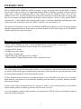
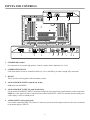
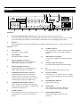
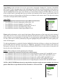
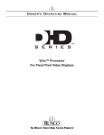
Rear Panel
5
6
11
13
SYSTEM CONTROL INTERFACE
INPUTS
Serial No
Pr
R
Y
G
Pb
B
V
Runco International
Union City, CA
Y
G
CAUTION: TO REDUCE THE RISK OF ELECTRIC
SHOCK, DO NOT REMOVE COVER. NO USERSERVICEABLE PARTS INSIDE. REFER SERVICING
TO QUALIFIED SERVICE CENTER.
HD1
2
1
Pr
R
!
AVIS: RISQUE DE CHOC ELECTRIQUE-NE PAS OUVRIR
TRIGGERS
3
IR
Model
OUTPUTS
CAUTION
RISK OF ELECTRIC SHOCK
DO NOT OPEN
H
WARNING: TO REDUCE THE RISK OF FIRE
Pb
B
OR ELECTRIC SHOCK, DO NOT EXPOSE
THIS APPLIANCE TO RAIN OR MOISTURE.
HD2
Video Processor / Controller
R
Pr
G
Y
B
Pb
H
V
SDI
Pb
Pr
S-Video 1
Y
100-230VAC 50-60 Hz, 165 Watts Max
H
V
1
H/V
DVI Out
DVI 1
DVI 2
2
3
4
Option
Component Video
Video
7
8
S-Video 2 RS-232 Out
9
10
12
RS-232 Control
14
Made In USA
15
16
17
OUTPUTS:
1.
ANALOG OUTPUTS (BNC Connectors) (This output is not used when married to the VX-2c)
The various output lines used to drive the analog input of the display device. Individually, the jacks are: V=vertical
sync, H=horizontal sync, B=Blue, G=Green, R=Red. Connect these to the corresponding projector inputs.
2.
DVI OUT
The DVI digital link used to drive the digital input of an HDCP compliant display device. Connect to the projector’s
DVI inputs.
INPUTS:
10.
S-VIDEO 2 INPUT
This is the input for S-video #2 from sources such
3.
DVI 1 (Digital)
as Satellite receivers, S-VHS VCR’s and DVD
DVI input #1, HDCP compliant.
players.
4.
DVI 2 (Digital)
11.
TRIGGERS 1/2/3 (Outputs)
DVI input #2, HDCP compliant.
Connection for 3 different 12V trigger controlled
devices.
5.
HD 1 (Analog BNC connectors)
High Definition input #1, accepts RGB(HV) or
12.
RS-232 OUT (RJ-11 Connector)
YPrPb, 480p, 720p, 480i, 576i or 1080i.
To transmit control signals to the plasma display.
6.
HD 2 (Analog BNC connectors)
13.
IR
High Definition input #1, accepts RGB(HV) or
Wired input from an external remote control.
YPrPb, 480p, 720p, 480i, 576i or 1080i.
7.
COMPONENT INPUT (RCA connectors)
Standard Definition (480i/576i) Component
(YPrPb) input. This is the input for component
video from sources such as DVD players. (Do not
set DVD player in progressive output mode).
8.
COMPOSITE INPUT (RCA connector)
This is the input for Composite Video input from
sources such as Laser disc players, VCRs and other
miscellaneous video sources.
9.
S-VIDEO 1 INPUT
This is the input for S-video #1 from sources such
as Satellite receivers, S-VHS VCR’s and DVD
players.
12
14.
RS-232 CONTROL
Connection for an external RS-232 controller
device to integrate the DHD with system automation
control.
15.
POWER INPUT (100-230v)
Plug in main power here.
16.
MAIN FUSE
This is the main AC input fuse. (Main Fuse:
5mm x 20mm, 500mA, 250V, Slow Blow)
17.
MAIN POWER SWITCH
Disconnects or applies main power to the
processor.