1
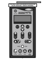
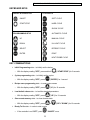
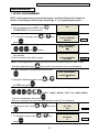
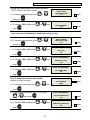
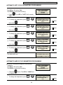
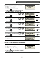
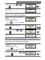
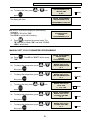
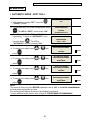
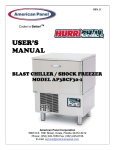
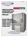
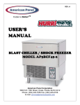
REV. E Cooler is Better!TM USER’S MANUAL BLAST CHILLERS (SHOCK FREEZERS) MODEL AP24BC250-3 MODEL AP24BCF300-3 MODEL AP40BC350-3 MODEL AP40BCF450-3 American Panel Corporation 5800 S.E. 78th Street, Ocala, Florida 34472-3412 Phone: (352) 245-7055 Fax: (352) 245-0726 E-mail: [email protected] AP24BC250-3, AP24BCF300-3, AP40BC350-3, AP40BCF450-3 Manual INDEX INTRODUCTION 3 CONTROLLER FEATURES OPERATING MODES AUTOMATIC MODE MANUAL MODE OPERATING CYCLES PRINTER (OPTIONAL) PC CONNECTION (OPTIONAL) 3 3 3 4 4 4 4 INSTALLATION OF REMOTE UNITS 5 REQUIREMENTS TO BE MET DURING INSTALLATION (8 STEPS) INSTALLATION AT THE SAME LEVEL INSTALLATION AT DIFFERENT LEVELS CONNECTION PIPING FOR REMOTE CONDENSING UNITS 5 5 6 6 INSTALLATION 7 WARNINGS PREPARATION INSTALLATION LOCATION DIMENSIONS ELECTRICAL AND REFRIGERATION SPECIFICATIONS CONNECTION TO THE REMOTE UNIT CONDENSATE DRAINAGE CONNECTION VERIFYING CORRECT INSTALLATION SPACES AROUND THE CABINET STARTING & TESTING THE UNIT 7 7 7 7 7 8 8 8 8 9 9 USING THE HURRICHILL™ TECHNOLOGY 10 BLAST CHILLING SHOCK FREEZING SOFT CHILL CYCLE HARD CHILL CYCLE SHOCK FREEZE CYCLE 10 10 10 10 10 PANNING AND LOADING 11 PANNING LOADING 11 11 CONTROL PANEL FOR MODELS AP24 & AP40 BLAST CHILLERS / SHOCK FREEZERS 12 KEYBOARD KEYS KEY COMBINATIONS 13 13 PROGRAMMING 14 1. INITIAL PROGRAMMING 2. PROGRAMMING THE CYCLES AUTOMATIC SOFT CYCLE PARAMETERS PROGRAMMING AUTOMATIC HARD CYCLE PARAMETERS PROGRAMMING AUTOMATIC SHOCK CYCLE PARAMETERS PROGRAMMING UV LIGHT CYCLE PARAMETERS PROGRAMMING DEFROST CYCLE PARAMETERS PROGRAMMING HEATED PROBE CYCLE PARAMETERS PROGRAMMING 14 17 18 18 19 20 21 21 1 AP24BC250-3, AP24BCF300-3, AP40BC350-3, AP40BCF450-3 Manual MANUAL SOFT CYCLE PARAMETERS PROGRAMMING MANUAL HARD CYCLE PARAMETERS PROGRAMMING MANUAL SHOCK CYCLE PARAMETERS PROGRAMMING 3. RECIPE NAME PROGRAMMING 22 23 24 25 OPERATION 26 1. 2. 3. 4. 5. 6. 7. 8. 9. 26 27 28 29 29 29 30 31 32 AUTOMATIC MODE - SOFT CHILL MANUAL MODE - SOFT CHILL HARD CHILL CYCLE SHOCK FREEZE CYCLE UV (STERILIZATION) CYCLE DEFROST CYCLE HEATED FOOD PROBE PREPARING AND USING THE OPTIONAL PRINTER TO CLEAR DATA PRINTER 32 LOADING A ROLL OF PAPER REMOVING A ROLL OF PAPER OPERATING THE PRINTER MAINTENANCE REPLACING THE RIBBON (NO PAPER IN THE PRINTER) REPLACING THE RIBBON (WITH PAPER IN THE PRINTER) 33 33 33 33 33 34 MAINTENANCE AND CLEANING 34 CLEANING THE CONDENSER CLEANING THE STORAGE COMPARTMENT 34 35 WIRING DIAGRAMS 35 COMPUTER CONNECTION 39 PARTS LIST 40 STANDARD WARRANTY 41 ORDERING PRINTER SUPPLIES (RIBBON & PAPER) 42 2 AP24BC250-3, AP24BCF300-3, AP40BC350-3, AP40BCF450-3 Manual INTRODUCTION Blast Chiller Models AP24BC250-3 and AP40BC350-3 are used to rapidly chill cooked foods to temperatures suitable for refrigerated storage. They are capable of lowering the core temperature of most foods from 160o F to 40o F in 90 minutes. Chiller/Freezer Models AP24BCF300-3 and AP40BCF450-3 have the same chilling capabilities as the Blast Chiller Models and when the shock freezing option is selected, are capable of lowering the core temperature of most foods from 160o F to 0o F in 4 hours. Food is loaded into 12" x 20" x 2-1/2" pans. AP24 and AP40 models are sized to accept one rack containing up to 40 pans (24 for AP24). All models can have as options: UV sterilization, an integral temperature recording device (printer) and 2 or 4 food probes instead of one. All models employ a high velocity flow of cooled air to assure even cooling of the food product, and to quickly bring the food temperature through the danger zone in which bacteria multiply rapidly. This is done in accordance with the requirements of HACCP, FDA and all applicable state regulations. CONTROLLER FEATURES The electronic control system is solid state and is based on the latest microprocessor technology. The display is VFD Industrial Type. It displays (4) lines of 20 characters each and allows operator viewing from any angle. The display is programmed to show clear step-by-step instructions and operating data. It is capable of storing 250 sets of data and 150 recipes. The unit has built-in safety and self-diagnostic systems. The controller notifies the operator if various faults, as listed below, should occur: ¾ Power supply failure / Restoration of power ¾ Faulty air temperature probe ¾ Faulty food temperature probe ¾ High air temperature (above 140o F) ¾ Low air temperature (below -35o F) ¾ High food temperature (above 180o F) ¾ Low food temperature (below 35o F) As an option, the unit can be operated by a PC. The PC interface allows the operator to remotely program the unit, operate it, download the data and print the data. OPERATING MODES The operator can choose from the following modes: AUTOMATIC MODE This is the preferred mode, in which all the food probes are active and take part in controlling the chilling or freezing process. The cycle will never proceed to its next step until all the probes have reached their set breaking temperatures. The operator needs only to select the recipe number of the food to be controlled by each probe (up to 150 recipes can be programmed), then insert each probe into its food. It is recommended that the operator remove the food when its temperature starts to flash and the display shows “Ready”. The unit will automatically switch into holding mode (cavity air temperature between 35o F and 42o F) when all the food have reached the end cycle programmed temperature. 3 AP24BC250-3, AP24BCF300-3, AP40BC350-3, AP40BCF450-3 Manual MANUAL MODE Operating time is set manually, by the operator, for the meal that has been chosen. Air temperature is controlled by the air probe. If the food probes have been inserted into the food they will provide temperature readouts only. The unit will automatically switch into the holding mode at the end of the cycle. OPERATING CYCLES The operator can choose from the following 6 operating cycles: MODE FOOD TEMP. AT END SOFT CHILL 38 F TO 40 F o o o o HARD CHILL 38 F TO 40 F SHOCK FREEZE DEFROST 0 F N/A UV (optional) N/A HEAT PROBE N/A o USES NOTES: FOR LOW DENSITY FOODS AIR TEMP. IS 28 F TO 35 F FOR MEDIUM & HIGH DENSITY FOODS FOR LONGER STORAGE TO DEFROST THE EVAPORATOR, NOT THE FOOD TO STERILIZE THE CAVITY, NOT THE FOOD TO HEAT THE FOOD PROBE o o o o AIR TEMP. STARTS AT 0 F, RISES TO 28 F TO o o 35 F WHEN FOOD CORE TEMP. REACHES 60 F o AIR TEMP. IS -25 F USE AFTER SHOCK FREEZING CYCLE USE WHEN DESIRED ALLOWS EASIER EXTRACTION FROM THE FOOD NOTE: All Chill & Freeze Cycles automatically go into HOLDING MODE when the selected temperature is reached and remain there until the operator stops the cycle. PRINTER (OPTIONAL) An optional strip recorder provides a record of the unit’s operating parameters during the cycle and the following holding period. The information recorded includes date, time, cycle identification, product identification and product core temperature at prescribed intervals. PC CONNECTION (OPTIONAL) The unit can be programmed and operated from a remote PC via modem and software (Windows 95, 98, NT, XP). Maximum distance is 4000 ft. Full instructions are supplied on a computer disc, which is furnished when the computer connection is ordered. 4 AP24BC250-3, AP24BCF300-3, AP40BC350-3, AP40BCF450-3 Manual INSTALLATION OF REMOTE UNITS REQUIREMENTS TO BE MET DURING INSTALLATION (8 STEPS) COMPRESSOR FIG. 1 1. Inclination of the piping. FIG. 2 2. Fastening of brackets on insulated piping. FIG. 3 3. Airtight welding. FIG. 4 4. Create the vacuum and load the line. 5. Check for leaks. 6. Open the shut-off valves (A & B, FIG.4) on both sides of remote unit and of cabinet. 7. Check the exact load of refrigerant in the liquid passage gauge. 8. Make sure all the refrigerant taps are open. INSTALLATION AT THE SAME LEVEL If the condensing unit is going to be installed at the same level with the cabinet, follow the instructions in FIG. 5 FIG. 5 5 AP24BC250-3, AP24BCF300-3, AP40BC350-3, AP40BCF450-3 Manual INSTALLATION AT DIFFERENT LEVELS If the remote condensing unit is installed at a higher level than the cabinet (FIG. 6) insert a siphon in the return line at every 6 ft. of difference in height. If the remote condensing unit is installed at a lower level than the cabinet (FIG. 7) it is not necessary to insert any siphons. FIG. 7 FIG. 6 Insert a siphon at the beginning (a) and at the end (b) of each riser CONNECTION PIPING FOR REMOTE CONDENSING UNITS MODEL SUPPLY LINE DIA. INTAKE LINE DIA. AP24BC250-3 1/2" 1-1/8" AP24BCF300-3 5/8" 1-3/8" AP40BC350-3 5/8" 1-3/8" AP40BCF450-3 7/8' 1-5/8" 6 AP24BC250-3, AP24BCF300-3, AP40BC350-3, AP40BCF450-3 Manual INSTALLATION WARNINGS READ ALL OF THE INSTRUCTIONS IN THIS MANUAL BEFORE YOU ATTEMPT TO INSTALL THE EQUIPMENT. ALWAYS DISCONNECT THE UNIT FROM THE POWER SOURCE BEFORE PERFORMING ANY SERVICE OR MAINTENANCE. INSTALLATION AND SERVICE MUST BE PERFORMED BY A QUALIFIED SERVICE AGENCY APPROVED & AUTHORIZED BY AMERICAN PANEL CORPORATION. DOING OTHERWISE MAY VOID THE WARRANTY. Note: Any changes made to the equipment without authorization from the factory will void the warranty. PREPARATION Check the integrity of the unit once it is unpacked. Check that the available power supply corresponds to the ratings on the unit's nameplates and that correctly rated electrical protection is provided. Quick disconnect must be provided for this unit by the installer. If additional refrigerant should be needed, be certain to use the correct type. Make certain that adequate drainage is provided; Be certain that the remote condensing unit is positioned within the range indicated on page 8 (CONNECTION TO THE REMOTE UNIT) in this manual and that it is connected as specified and in accordance with all applicable electrical codes. INSTALLATION ALL MODELS HAVE REMOTE CONDENSING UNITS. The condensing unit and the cabinet must be connected and installed in accordance with the following instructions: LOCATION Ambient air temperature for air cooled condensing units should be no greater than 90oF to ensure the rated performance. A remote condensing unit must be located away from direct sunlight if installed outdoors, or, if it is indoors, a water cooled condensing unit should be used. DIMENSIONS MODEL LEFT - RIGHT FRONT - BACK HEIGHT FRONT-BACK W/ DOOR OPEN AP24BC250-3 54-3/8” 46-1/4” 86-5/8” 81” AP24BCF300-3 54-3/8” 46-1/4” 86-5/8” 81” AP40BC350-3 59” 50-1/8” 86-5/8” 85” AP40BCF450-3 59” 50-1/8” 86-5/8” 85” 7 AP24BC250-3, AP24BCF300-3, AP40BC350-3, AP40BCF450-3 Manual ELECTRICAL AND REFRIGERATION SPECIFICATIONS MODEL VOLTAGE CABINET REMOTE CONSENSER POWER SUPPLY BTU/H AT 14°F EVAP. TEMP. TYPE AMPS CORD & 105°F COND. TEMP. 8 14-4 25,000 MEDIUM TEMP. -10°F/+40°F AP24BC250-3 208/3/60 AP24BCF300-3 208/3/60 8 14-4 AP40BC350-3 208/3/60 10 14-4 35,000 MEDIUM TEMP. -10°F/+40°F AP40BCF450-3 208/3/60 10 14-4 70,000 MEDIUM/LOW TEMP. -40°F/+40°F 50,000 MEDIUM/LOW TEMP. -40°F/+40°F NOTES: 1. The condensing unit and the cabinet must be connected to separate electrical power supplies. 2. Each wire must be connected to its corresponding terminal. 3. The ground wire must be connected to an efficient ground terminal. CONNECTION TO THE REMOTE UNIT The specified diameters (see chart on page 6) for the copper tubing used to connect the remote condensing unit to the cabinet are adequate for a separation of up to 60 feet. For greater distances, contact the factory for instructions. NOTES: 1. The insulation used on the piping must be of high quality and must have closed cells. 2. Refer to pages 5 and 6 for connection drawings. 3. Quick disconnects MUST be mounted where shown. 4. Note the information regarding the installation of siphons (traps) when the cabinet and the remote condensing unit are at different levels. They are NOT needed when the condensing unit is at a lower level than the cabinet. CONDENSATE DRAINAGE CONNECTION It is important that the condensate from the evaporator is properly drained. The drain line from the evaporator exits from the rear of the cabinet. It must be connected in conformance with local regulations. VERIFYING CORRECT INSTALLATION a. b. c. d. e. Check that there are no refrigerant leaks. Check that the refrigerant piping is insulated fully and correctly. Check that siphons (traps) have been installed. Check that the required quick disconnects have been installed. Check all electrical connections and that the power supply is of proper voltage (208 VAC +/- 5%, 3 ph., 60 Hz.). f. If the condensing unit is water cooled, check the connection to the water supply and the setting of the pressure valve. g. Check the provision for drainage of condensate water. h. If a unit has been transported in a non-vertical position (e.g. on its back) or if it has been overturned during installation, WAIT AT LEAST TWELVE HOURS BEFORE TURNING IT ON. i. If the condensing unit has been outside in cold temperatures, turn on the power to it for at least twelve hours before installation. j. Make sure that the refrigerant is Type 404A and adjust the expansion valve if necessary. k. Make sure that the fans of an air cooled condensing unit blow the air "UP". 8 AP24BC250-3, AP24BCF300-3, AP40BC350-3, AP40BCF450-3 Manual l. Make sure that the fans inside the cabinet rotate clockwise. m. Make sure that the cabinet has been leveled. SPACES AROUND THE CABINET x At least 15" clear space is required above the unit for service. x At least 6" clear space is required on both sides of the cabinet. x At least 6" clear space is required on the rear of the cabinet for drain hookup and maintenance. x Enough space should be provided in front of the cabinet to fully open the door. The same space should be provided on the back of the cabinet for units with pass-thru doors. STARTING & TESTING THE UNIT 1. To charge the unit, use the "HARD" cycle and the "MANUAL" mode. Set for two hours of operation to allow enough time to fully charge the unit. IMPORTANT: Immediately after starting the unit, check that the fans inside the cabinet are rotating CLOCKWISE, and that the fans in the condensing unit are rotating in accordance with the arrows on the blades. Improper rotation will damage the unit and void the warranty. 2. Start the unit per 1. above and in accordance with the following operating instructions, then perform at least one complete blast chilling or shock freezing cycle. When done, instruct the client on the correct use of the unit. 3. By the end of the cycle the unit should have pulled down to 0o F (AP24BCF300-3, AP40BCF450-3) or 10 o F (AP24BC250-3, AP40BC350-3). It should have been cycling between 0o F and 10o F (AP24BCF300-3, AP40BCF450-3) or between 10o F and 20o F (AP24BC250-3, AP40BC350-3) and the sight glass must be clear. 4. As soon as possible after the unit has been started, check the power consumption, the standard pressure measurements and the operation of all the controls. NOTE: The refrigerating system works on pressure. An electro valve mounted on the top of the cabinet is controlled by the electronic controller. When the temperature of the air in the cabinet falls to the programmed low temp setting, the electro valve will close (0 VAC) and the unit will pump down. When the temperature of the air in the cabinet rises to the programmed high temp setting, the electro valve will open and refrigeration will start. 9 AP24BC250-3, AP24BCF300-3, AP40BC350-3, AP40BCF450-3 Manual USING THE HURRICHILL™ TECHNOLOGY BLAST CHILLING All cooked food rapidly loses its quality and aroma if it is not served promptly. Natural bacteria growth, the main reason why food becomes stale, takes place at an exponential rate between 140°F and 40°F. However lower temperatures have a hibernating effect that increases as the temperature drops, thereby gradually reducing bacterial activity until it stops altogether. Only fast reduction of the temperature at the product's core allows its initial characteristics to be maintained intact. The HurriChill™ blast chiller gets food through this high-risk temperature band rapidly, cooling the core of the product to 40°F within 90 minutes. This conserves food quality, color and aroma while increasing its storage life. After blast chilling, the food can be preserved at 38˚F for up to 5 days. SHOCK FREEZING For storage over the medium-long term, food has to be shock frozen (to 0°F or below). Freezing means converting the water contained in food into crystals. Thanks to the high speed at which low temperature penetrates the food, the HurriChill™ shock freezer assures the formation of small crystals (micro-crystals) that do not damage the product in any way. Uncooked raw products, semi-processed foods and cooked foods can be treated safely. When the food is thawed, no liquids, consistency, weight or aroma will be lost, and all its initial qualities will remain unchanged. SOFT CHILL CYCLE (160°F to 40°F) This cycle is recommended for "delicate", light, thin products or small piece sizes, such as vegetables, creams, sweets, fish products and fried foods. Soft chilling lowers the food temperature quickly, but extremely delicately so as not to damage the outside of the food. This is the ideal cycle to chill any food quickly but delicately, even in haute cuisine. HARD CHILL CYCLE (160°F TO 40°F) Hard chilling is suited for "dense" products and products with a high fat content, in large pieces or those products typically more difficult to chill. Careful chilling control ensures that the end temperature of 40°F is reached at the core of the product, with no danger of freezing and damaging the product, not even on its surface. SHOCK FREEZE CYCLE (160°F TO 0°F) This cycle is recommended when you want to store food for several weeks or months at temperatures below 0°F. Freezers are suited for storing ready frozen foods, but not for freezing them. During shock freezing, the liquids contained in the food are transformed into micro-crystals that do not harm the tissue structure. When the food is thawed, its quality will be excellent. It is especially suited for all semi-processed foods and raw products. 10 AP24BC250-3, AP24BCF300-3, AP40BC350-3, AP40BCF450-3 Manual PANNING AND LOADING PANNING 1. Standard pan depth is 2-1/2”. Other depths can be used but are not recommended as their use would require an increase in the cycle time. 2. Stainless steel or aluminum pans are recommended, as plastic containers will increase the chilling time. 3. Crockery or stainless steel cylinders, 6” dia. and 10” max. height, are acceptable. 4. Slack filled Cryovac bags can be used if placed on wire shelves. 5. Most foods should be covered with stainless steel or aluminum lids, or with aluminum foil. 6. Foods should be left UNCOVERED in the following circumstances: a. When a dry surface is desired, such as with fried chicken, fish or potatoes. b. When the food has a relatively large surface, such as with chicken breasts, Salisbury steaks, etc. c. For large roasts of beef, turkey, etc. d. For pastry and other bakery products. 7. Some foods, such as roast beef, will continue to cook after removal from the oven. To avoid this, they should be chilled uncovered. 8. Food probes should be at the center of the food in the pan. 9. Always wipe the probe with an alcohol swab after removing it from the food then place the probe in the holding device. LOADING 1. Place the pans on the mobile cart so that the pan ends will face the fans and the cold air will be drawn over the length of the pans. 2. The shelves should be loaded so that there is no less than 1 inch between the bottom of one pan and the top of the next. Also be certain that there is sufficient space between the top of any probe and the bottom of the pan above. 3. Place the loaded cart in the center of the chilling cabinet between the refrigeration coil and the fans. 11 AP24BC250-3, AP24BCF300-3, AP40BC350-3, AP40BCF450-3 Manual CONTROL PANEL FOR MODELS AP24 & AP40 BLAST CHILLERS / SHOCK FREEZERS 12 AP24BC250-3, AP24BCF300-3, AP40BC350-3, AP40BCF450-3 Manual KEYBOARD KEYS ON/OFF & START/STOP CYCLE KEYS ON/OFF SOFT CYCLE START/STOP HARD CYCLE SHOCK CYCLE AUTOMATIC CYCLE PROGRAMMING KEYS UP MANUAL CYCLE DOWN UV LIGHT CYCLE SELECT DEFROST CYCLE ENTER PRINT HEAT PROBE CYCLE KEY COMBINATIONS ¾ Initial Programming state – to initially set the device o With the display reading "OFF", press and hold (“START/STOP”) for 5 seconds ¾ Cycles programming state – to initially set the cycles o With the display reading "OFF", press (“ENTER”) for 1 second ¾ Recipe name programming state – to enter recipe names o With the display reading "OFF", press (“A”) for 10 seconds ¾ Load default values state – to load the standard parameters o With the display reading "OFF", press (”UP”) for 10 seconds ¾ Clear events memory state – to clear obsolete data o With the display reading "OFF", press + (”UP”+”DOWN”) for 10 seconds ¾ Ready To Go state – in order to start a cycle O “ON/OFF” once. If the controller is not "OFF", press 13 AP24BC250-3, AP24BCF300-3, AP40BC350-3, AP40BCF450-3 Manual PROGRAMMING 1. INITIAL PROGRAMMING NOTE: Initial programming is preset at the factory. Use this section only if changes are desired. If no changes are to be made, skip to Page 17 ( 2. Programming the cycles ). OFF a. With the display reading "OFF", press ("START/STOP") for a few seconds. INITIAL PROGRAMMING b. To change the language, press press or then SELECT LANGUAGE ENGLISH . c. Enter the default password by pressing, in order, the and buttons. If the entered password is wrong the display will show, for 3 seconds: Then the controller will go back to step c. ENGLISH Blinks INITIAL PROGRAMMING ENTER PASSWORD: *** INITIAL PROGRAMMING WRONG PASSWORD TRY AGAIN TRY AGAIN Blinks NOTE: If a wrong password is introduced three times the controller will go into “OFF” state. During the password typing, button can be used to delete one or more characters. d. If you do not wish to change the password, press INITIAL PROGRAMMING . CHANGE PASSWORD? NO or To change the default password, press for "YES" then press . The password will always be a combination of three of the six available cycles: ("SOFT", "HARD", "SHOCK", "DEF", "UV", "HEAT PROBE"). . Type the new password, then press Be sure to remember the new password and keep a record of it in a safe place. INITIAL PROGRAMMING e. To change the year, press or then press SET YEAR 2006 . 2006(year) Blinks INITIAL PROGRAMMING f. To change the month, press press or then . 14 SET MONTH 07 07(month) Blinks AP24BC250-3, AP24BCF300-3, AP40BC350-3, AP40BCF450-3 Manual INITIAL PROGRAMMING g. To set the day, press or then press SET DAY 03 . h. To set the hour, press or (be sure to continue to press the buttons until the hour and "AM" or "PM" show correctly) then press 03(day) Blinks INITIAL PROGRAMMING SET TIME 10:25 AM . 10(hours) Blinks INITIAL PROGRAMMING i. To set the minutes, press or then press SET TIME 10:25 AM . 25(minutes) Blinks INITIAL PROGRAMMING j. To change the number of probes, press then press or k. To change the temperature, press INITIAL PROGRAMMING HIGH AIR ALARM 140 °F or 140 Blinks . The low air alarm temperature should be left at -35 oF *. However, if a change is desired: l. To change the temperature, press then press 1 Blinks . The high air alarm temperature should be left at 140 oF. However, if a change is desired: then press AIR PROBES NUMBER? 1 INITIAL PROGRAMMING LOW AIR ALARM -35 °F * or -35 Blinks . o *- 35 F for shock freezers (AP24BCF300-3, AP40BCF450-3) - 5o F for blast chillers (AP24BC250-3, AP40BC350-3) INITIAL PROGRAMMING m. To change the number of probes, press then press or FOOD PROBES NUMBER? 1 1 Blinks . NOTE: Standard configuration has only one food probe. However, a maximum of 4 probes can be used with these models. The high food alarm temperature should be left at 180 oF. However, to make a change: n. To change the temperature, press then press INITIAL PROGRAMMING HIGH FOOD ALARM 180 °F or . 15 180 Blinks AP24BC250-3, AP24BCF300-3, AP40BC350-3, AP40BCF450-3 Manual The low food alarm temperature should be left at 35 oF. However, to make a change: o. To change the temperature, press then press or INITIAL PROGRAMMING SOFT & HARD LOW FOOD ALARM 35 °F 35 Blinks . INITIAL PROGRAMMING p. To change to YES or NO, press or then SHOCK FREEZE? YES * YES Blinks . press * YES for shock freezers (AP24BCF300-3, AP40BCF450-3) NO for blast chillers (AP24BC250-3, AP40BC350-3) and go to step r. q. To change the temperature, press INITIAL PROGRAMMING SHOCK FREEZE LOW FOOD ALARM -5 °F or -5 Blinks . then press INITIAL PROGRAMMING r. To change to YES or NO, press press or then UV CYCLE? NO NO Blinks . INITIAL PROGRAMMING s. To change to YES or NO, press press or then DEFROST CYCLE? YES YES Blinks . INITIAL PROGRAMMING t. To change to YES or NO, press press or then PC CONNECTION? NO NO Blinks . For YES, the display will show: The P.C. baud rate should be left at 38400. However, to make a change: PC BAUDRATE 38400 or u. To change the baud rate, press press INITIAL PROGRAMMING 38400 Blinks then . v. To change the number (between 01 & 32), press or then press INITIAL PROGRAMMING CHILLER NETWORK ID # 01 . 01 Blinks INITIAL PROGRAMMING w. To change to YES or NO, press press or then . 16 PRINTER CONNECTION? NO NO Blinks AP24BC250-3, AP24BCF300-3, AP40BC350-3, AP40BCF450-3 Manual For YES, the display will show: The printer baud rate should be left at 1200. However, to make a change: x. To change the baud rate, press press INITIAL PROGRAMMING PRINTER BAUDRATE 1200 or 1200 Blinks then . INITIAL PROGRAMMING y. To change the timing, press press or then PRINT & SAVE EVENTS EVERY 15 MIN 15 Blinks . INITIAL PROGRAMMING z. To change to YES or NO, press press or then PRINT DURING CYCLE NO NO Blinks . INITIAL PROGRAMMING aa. To change to YES or NO, press or then RECIPES? NO NO Blinks . press INITIAL PROGRAMMING bb. To change to YES or NO, press press or then NAFEM COMMUNICATION NO NO Blinks . INITIAL PROGRAMMING The display will show for 2 seconds: Then the controller will go into “OFF” state. COMPLETE NOTE: During programming key can be used to return to the previous screen (except at the steps 1h, 1i and 3d, when it has different functions). key is used to confirm the settings and advance to the next screen. At any time, to bring the controller to “OFF” state, just pres the (“ON/OFF”) button. 2. PROGRAMMING THE CYCLES OFF a. With the display reading "OFF", press . b. Enter the password (see page 14), then press PARAM. PROGRAMMING ENTER PASSWORD *** . 17 AP24BC250-3, AP24BCF300-3, AP40BC350-3, AP40BCF450-3 Manual AUTOMATIC SOFT CYCLE PARAMETERS PROGRAMMING The LED for "A" will be "ON". The LED'S for cycles will be blinking. c. Press "ON". . The LED for "SOFT" will be steady d. To change the temperature, press then press or 35 Blinks PARAM. PROGRAMMING AUTOMATIC SOFT CYCLE FOOD TEMPERATURE 40 °F or 40 Blinks PARAM. PROGRAMMING AUTOMATIC SOFT CYCLE HOLDING LOW TEMP. 35 °F or 35 Blinks PARAM. PROGRAMMING AUTOMATIC SOFT CYCLE HOLDING HIGH TEMP. 42 °F 42 Blinks . h. To change the temperature, press then press PARAM. PROGRAMMING AUTOMATIC SOFT CYCLE HIGH AIR TEMPERATURE 35 °F . g. To change the temperature, press then press 28 Blinks . f. To change the temperature, press then press or PARAM. PROGRAMMING AUTOMATIC SOFT CYCLE LOW AIR TEMPERATURE 28 °F . e. To change the temperature, press then press PARAM. PROGRAMMING AUTOMATIC MODE CHOOSE PROGRAMMING CYCLE or . PARAM. PROGRAMMING AUTOMATIC SOFT CYCLE The display will show: PROGRAMMING COMPLETE AUTOMATIC HARD CYCLE PARAMETERS PROGRAMMING After about 2 seconds the display will automatically change to: The LED for "A" will be "ON". The LED'S for cycles will be blinking. PARAM. PROGRAMMING AUTOMATIC MODE CHOOSE PROGRAMMING CYCLE i. Press the button. The LED for "HARD" will be steady "ON". j. To change the temperature, press PARAM. PROGRAMMING AUTOMATIC HARD CYCLE LOW AIR TEMP PART 1 0 °F * or 18 0 Blinks AP24BC250-3, AP24BCF300-3, AP40BC350-3, AP40BCF450-3 Manual then press . * 0o F for shock freezers (AP24BCF300-3, AP40BCF450-3) 10o F for blast chillers (AP24BC250-3, AP40BC350-3) k. To change the temperature, press then press or PARAM. PROGRAMMING AUTOMATIC HARD CYCLE HIGH AIR TEMP PART 1 10 °F ** 10 Blinks PARAM. PROGRAMMING AUTOMATIC HARD CYCLE BREAKING TEMP 60 °F 60 Blinks PARAM. PROGRAMMING AUTOMATIC HARD CYCLE LOW AIR TEMP PART 2 28 °F 28 Blinks PARAM. PROGRAMMING AUTOMATIC HARD CYCLE HIGH AIR TEMP PART 2 35 °F 35 Blinks PARAM. PROGRAMMING AUTOMATIC HARD CYCLE HARD FOOD TEMP. 40 °F 40 Blinks PARAM. PROGRAMMING AUTOMATIC HARD CYCLE HOLDING LOW TEMP. 35 °F 35 Blinks . o ** 10 F for shock freezers (AP24BCF300-3, AP40BCF450-3) 20o F for blast chillers (AP24BC250-3, AP40BC350-3) l. To change the temperature, press then press . m. To change the temperature, press then press or . q. To change the temperature, press then press or . p. To change the temperature, press then press or . o. To change the temperature, press then press or . n. To change the temperature, press then press or PARAM. PROGRAMMING AUTOMATIC HARD CYCLE HOLDING HIGH TEMP. 42 °F or . PARAM. PROGRAMMING AUTOMATIC HARD CYCLE The display will show: PROGRAMMING COMPLETE AUTOMATIC SHOCK CYCLE PARAMETERS PROGRAMMING 19 42 Blinks AP24BC250-3, AP24BCF300-3, AP40BC350-3, AP40BCF450-3 Manual After about 2 seconds the display will automatically change to: The LED for "A" will be "ON". The LED'S for cycles will be blinking. PARAM. PROGRAMMING AUTOMATIC MODE CHOOSE PROGRAMMING CYCLE button (for shock freezers only). r. Press the The LED for "SHOCK" will be steady "ON". s. To change the temperature, press then press or -15 Blinks PARAM. PROGRAMMING AUTOMATIC SHOCK CYCLE FOOD TEMPERATURE 0 °F or 0 Blinks PARAM. PROGRAMMING AUTOMATIC SHOCK CYCLE HOLDING LOW TEMP -4 °F or -4 Blinks PARAM. PROGRAMMING AUTOMATIC SHOCK CYCLE HOLDING HIGH TEMP 3 °F 3 Blinks . w. To change the temperature, press then press PARAM. PROGRAMMING AUTOMATIC SHOCK CYCLE HIGH AIR TEMPERATURE -15 °F . v. To change the temperature, press then press -25 Blinks . u. To change the temperature, press then press PARAM. PROGRAMMING AUTOMATIC SHOCK CYCLE LOW AIR TEMPERATURE -25 °F . t. To change the temperature, press then press or or . PARAM. PROGRAMMING The display will show: AUTO SHOCK CYCLE PROGRAMMING COMPLETE UV LIGHT CYCLE PARAMETERS PROGRAMMING After about 2 seconds the display will automatically change to: The LED for "A" will be "ON". The LED'S for cycles will be blinking. x. Press the button. The LED for "UV LIGHT" will be steady "ON". 20 PARAM. PROGRAMMING AUTOMATIC MODE CHOOSE PROGRAMMING CYCLE AP24BC250-3, AP24BCF300-3, AP40BC350-3, AP40BCF450-3 Manual y. To change the time, press press or then PARAM. PROGRAMMING UV CYCLE CYCLE TIME H 00:30 MIN 00:30 Blinks . PARAM. PROGRAMMING UV CYCLE The display will show: PROGRAMMING COMPLETE DEFROST CYCLE PARAMETERS PROGRAMMING After about 2 seconds the display will automatically change to: The LED for "A" will be "ON". The LED'S for cycles will be blinking. z. Press the button. The LED for "DEFROST" will be steady "ON". The defrost type must be left AIR FLOW. aa. Press PARAM. PROGRAMMING DEFROST CYCLE CHOOSE TYPE AIR FLOW . bb. To change the time, press press PARAM. PROGRAMMING AUTOMATIC MODE CHOOSE PROGRAMMING CYCLE or then PARAM. PROGRAMMING DEFROST CYCLE TOTAL TIME 05 MIN AIR FLOW Blinks 05 Blinks . PARAM. PROGRAMMING DEFROST CYCLE The display will show: PROGRAMMING COMPLETE NOTE: The defrost is done by running the evaporator fan for 5 minutes with the door open. HEATED PROBE CYCLE PARAMETERS PROGRAMMING After about 2 seconds the display will automatically change to: The LED for "A" will be "ON". The LED'S for cycles will be blinking. PARAM. PROGRAMMING AUTOMATIC MODE CHOOSE PROGRAMMING CYCLE button. The LED for "HEATED cc. Press the PROBE" will be steady "ON". dd. To change the temperature, press then press or . 21 PARAM. PROGRAMMING HEATED PROBE CYCLE HEATING TEMPERATURE 30 °F 30 Blinks AP24BC250-3, AP24BCF300-3, AP40BC350-3, AP40BCF450-3 Manual ee. To change the time, press press or then PARAM. PROGRAMMING HEATED PROBE CYCLE HEATING TIME 05 SEC 05 Blinks . PARAM. PROGRAMMING HEATED PROBE CYCLE The display will show: PROGRAMMING COMPLETE After about 2 seconds the display will automatically change to: The LED for "A" will be "ON". The LED'S for cycles will be blinking. ff. PARAM. PROGRAMMING AUTOMATIC MODE CHOOSE PROGRAMMING CYCLE Press to program the manual mode. The "M" LED will be steady "ON" and the 6 "CYCLE LED's" will all blink. MANUAL SOFT CYCLE PARAMETERS PROGRAMMING gg. Press "ON". . The LED for "SOFT" will be steady hh. To change the temperature, press then press ii. To change the temperature, press or ll. or 35 Blinks PARAM. PROGRAMMING MANUAL SOFT CYCLE TOTAL TIME H 01:30 MIN then 01:30 Blinks PARAM. PROGRAMMING MANUAL SOFT CYCLE HOLDING LOW TEMP 35 °F or 35 Blinks PARAM. PROGRAMMING MANUAL SOFT CYCLE HOLDING HIGH TEMP 42 °F 42 Blinks . To change the temperature, press then press PARAM. PROGRAMMING MANUAL SOFT CYCLE HIGH AIR TEMPERATURE 35 °F . kk. To change the temperature, press then press 28 Blinks . To change the time, press press PARAM. PROGRAMMING MANUAL SOFT CYCLE LOW AIR TEMPERATURE 28 °F . then press jj. or PARAM. PROGRAMMING MANUAL MODE CHOOSE PROGRAMMING CYCLE or . 22 AP24BC250-3, AP24BCF300-3, AP40BC350-3, AP40BCF450-3 Manual PARAM. PROGRAMMING MANUAL SOFT CYCLE The display will show: PROGRAMMING COMPLETE MANUAL HARD CYCLE PARAMETERS PROGRAMMING After about 2 seconds the display will automatically change to: The LED for "M" will be "ON". The LED'S for cycles will be blinking. PARAM. PROGRAMMING MANUAL MODE CHOOSE PROGRAMMING CYCLE mm.Press the button. The LED for "HARD" will be steady "ON". nn. To change the temperature, press then press or PARAM. PROGRAMMING MANUAL HARD CYCLE LOW AIR TEMP PART 1 0 °F * 0 Blinks PARAM. PROGRAMMING MANUAL HARD CYCLE HIGH AIR TEMP PART 1 10 °F ** 10 Blinks PARAM. PROGRAMMING MANUAL HARD CYCLE TIME 1 H 01:00 MIN 01:00 Blinks PARAM. PROGRAMMING MANUAL HARD CYCLE LOW AIR TEMP PART 2 28 °F 28 Blinks PARAM. PROGRAMMING MANUAL HARD CYCLE HIGH AIR TEMP PART 2 35 °F 35 Blinks PARAM. PROGRAMMING MANUAL HARD CYCLE TIME 2 H 01:00 MIN 01:00 Blinks . o * 0 F for shock freezers (AP24BCF300-3, AP40BCF450-3) 10o F for blast chillers (AP24BC250-3, AP40BC350-3) oo. To change the temperature, press then press or . o ** 10 F for shock freezers (AP24BCF300-3, AP40BCF450-3) 20o F for blast chillers (AP24BC250-3, AP40BC350-3) pp. To change the time, press press or . qq. To change the temperature, press then press rr. or . To change the temperature, press then press or . ss. To change the time, press press then or then . 23 AP24BC250-3, AP24BCF300-3, AP40BC350-3, AP40BCF450-3 Manual tt. To change the temperature, press then press or PARAM. PROGRAMMING MANUAL HARD CYCLE HOLDING LOW TEMP. 35 °F 35 Blinks PARAM. PROGRAMMING MANUAL HARD CYCLE HOLDING HIGH TEMP. 42 °F 42 Blinks . uu. To change the temperature, press then press or . PARAM. PROGRAMMING MANUAL HARD CYCLE The display will show: PROGRAMMING COMPLETE MANUAL SHOCK CYCLE PARAMETERS PROGRAMMING After about 2 seconds the display will automatically change to: The LED for "M" will be "ON". The LED'S for cycles will be blinking. PARAM. PROGRAMMING MANUAL MODE CHOOSE PROGRAMMING CYCLE vv. Press the button (for shock freezers only). The LED for "SHOCK" will be steady "ON". ww. To change the temperature, press then press then press or PARAM. PROGRAMMING MANUAL SHOCK CYCLE HIGH AIR TEMPERATURE -15 °F -15 Blinks then PARAM. PROGRAMMING MANUAL SHOCK CYCLE TOTAL TIME H 04:00 MIN 04:00 Blinks PARAM. PROGRAMMING MANUAL SHOCK CYCLE HOLDING LOW TEMP. -4 °F -4 Blinks . zz. To change the temperature, press or . aaa.To change the temperature, press then press or . yy. To change the time, press then press -25 Blinks . xx. To change the temperature, press press or PARAM. PROGRAMMING MANUAL SHOCK CYCLE LOW AIR TEMPERATURE -25 °F or . 24 PARAM. PROGRAMMING MANUAL SHOCK CYCLE HOLDING HIGH TEMP. 3 °F 3 Blinks AP24BC250-3, AP24BCF300-3, AP40BC350-3, AP40BCF450-3 Manual PARAM. PROGRAMMING MANUAL SHOCK CYCLE The display will show: PROGRAMMING COMPLETE After about 2 seconds the display will automatically change to: PARAM. PROGRAMMING MANUAL MODE CHOOSE PROGRAMMING CYCLE NOTE: PROGRAMMING FOR "DEFROST", "UV" & "HEAT PROBE" WILL BE THE SAME IN MANUAL MODE AS IT IS IN AUTOMATIC MODE (see pages 20-22). 3. RECIPE NAME PROGRAMMING OFF a. With the display reading "OFF", press the button and hold it for 10 seconds. b. Enter your password (see page 14), then press RECIPES PROGRAMMING . c. Press ENTER PASSWORD *** or to change to the desired recipe number (from 1 to 150), then press move you to the "NAME" line. d. Using or required, then press 1 Blinks which will type the letters or numbers . To confirm the recipe and go to the next one press ENTER RECIPE NUMBER 1 ENTER RECIPE NAME . f a mistake is made in writing a recipe, use the desired location and correct it using to go to or . There is a blank space after number 9. It can be used to add a space or delete a letter. Press when the recipe is corrected. To finish the recipe name programming press (“ON/OFF”). 25 ENTER RECIPE NUMBER 1 ENTER RECIPE NAME CHICKEN_ _ Blinks AP24BC250-3, AP24BCF300-3, AP40BC350-3, AP40BCF450-3 Manual OPERATION 1. AUTOMATIC MODE - SOFT CHILL OFF a. With the display reading "OFF", press the (“ON/OFF”) button. b. To select the soft cycle, press the appropriate button . The LED for "SOFT" will be steady "ON". c. The LED's for “AUTOMATIC” and “MANUAL” are now blinking. To select an “AUTOMATIC” cycle, press RED FOOD PROBE ENTER RECIPE NUMBER 1 CHICKEN 1 Blinks YELLOW FOOD PROBE ENTER RECIPE NUMBER 2 ROAST BEEF or then 2 Blinks BLUE FOOD PROBE ENTER RECIPE NUMBER 1 CHICKEN or then 1 Blinks GREEN FOOD PROBE ENTER RECIPE NUMBER 2 ROAST BEEF 2 Blinks . g. To choose your recipe, press press then . f. To choose your recipe, press press SOFT CYCLE . e. To choose your recipe, press press or CHOOSE OPERATING CYCLE CHOOSE MODE AUTO / MAN press the button . The LED for “AUTOMATIC” will now be steady "ON". d. To choose your recipe, press OPERATING MODE or then . NOTE: This screen is shown only if the RECIPE parameter is set to “ON” in the INITIAL PROGRAMMING. A 4 food probe configuration is shown. The red food probe only will be active in the standard configuration. To enter additional recipe names, refer to Page 25 "RECIPE NAME PROGRAMMING". 26 AP24BC250-3, AP24BCF300-3, AP40BC350-3, AP40BCF450-3 Manual READY TO START The display will show: PRESS START alternating with 03.07.2006 AIR 1 10:28 AM 75°F 00:00 alternating with h. Press the cycle. PRESS START Blinks ("START/STOP") button to start the R / CHICKEN Y / ROAST BEEF B / CHICKEN G / ROAST BEEF The display will show briefly: STARTING CYCLE . . . Then the display will show: 03.07.2006 AIR 1 140°F 143°F 141°F 142°F 10:28 AM 75°F 00:00 alternating with R / CHICKEN Y / ROAST BEEF B / CHICKEN G / ROAST BEEF 140°F 143°F 141°F 142°F 00:00 Will count up The AUTOMATIC mode uses both the food probes and air probe temperatures to control the cycle. When all the food temperatures have reached the final setting of 40o F, the unit will automatically go into holding mode and a beep will sound for 5 seconds. The elapsed time and food temperature readouts will blink. 03.07.2006 AIR 1 The display will show: 11:57 AM 34°F alternating with R / CHICKEN Y / ROAST BEEF B / CHICKEN G / ROAST BEEF The operator can now end this cycle by pressing the The display will show briefly: 01:29 01:29 Blinks 40°F 40°F 40°F 40°F 40°F is alternating with Ready ("START/ STOP") button. STOPPING CYCLE . . . OPERATING MODE Then the display will show: CHOOSE OPERATING CYCLE 2. MANUAL MODE - SOFT CHILL 27 AP24BC250-3, AP24BCF300-3, AP40BC350-3, AP40BCF450-3 Manual F INSTEAD OF AUTOMATIC you wish to select a MANUAL cycle, perform steps 1.a, 1.b, 1.c, 1.d, 1.e, 1f and 1.g (above), except in step 1.c press button instead of button . The LED for "MANUAL" will then be steady "ON". The readouts in those steps will be the same as before. NOTE: Cycle time can be changed only in Cycle Programming mode. To change the programmed cycle time for any cycle see the instructions on Pages 17 to 25. h. Press the ("START/STOP") button to start the cycle. The display will show briefly: STARTING CYCLE . . . Then the display will show: 03.07.2006 AIR 1 10:41 AM 75°F 01:29 alternating with R / CHICKEN Y / ROAST BEEF B / CHICKEN G / ROAST BEEF 140°F 143°F 141°F 142°F 01:29 Will count down The MANUAL mode uses time and the air probe temperature to control the cycle. The default total time for a soft cycle is 90 minutes. After the 90 minutes the unit will automatically go into holding mode. 03.07.2006 AIR 1 The display will show: 10:41 AM 34°F 00:00 alternating with R / CHICKEN Y / ROAST BEEF B / CHICKEN G / ROAST BEEF The operator can now end this cycle by pressing The display will show briefly: 40°F 40°F 40°F 40°F ("START/ STOP"). STOPPING CYCLE . . . OPERATING MODE Then the display will show: CHOOSE OPERATING CYCLE 3. HARD CHILL CYCLE 28 00:00 Blinks AP24BC250-3, AP24BCF300-3, AP40BC350-3, AP40BCF450-3 Manual To perform a hard chill cycle, follow steps 1 or 2 (above), EXCEPT in step 1.b (above) press instead of . 4. SHOCK FREEZE CYCLE To perform a shock freeze cycle, follow steps 1 or 2 (above), EXCEPT in step 1.b (above) press instead of . 5. UV (STERILIZATION) CYCLE a. To perform a UV cycle remove all food, then press the b. Press the UV cycle. OPERATING MODE CHOOSE OPERATING CYCLE (“UV LIGHT”) button. ("START/STOP") button to start the 03.07.2006 11:43 AM UV CYCLE READY TO START The display will show briefly: STARTING CYCLE . . . Then the display will now show: 03.07.2006 11:43 AM UV CYCLE UV TIME After 30 minutes the display will show: The controller will beep for a few seconds. 29:59 READY TO START Blinks 29:59 Will count down to 00:00 03.07.2006 12:13 PM UV CYCLE COMPLETE The operator can now end this cycle by pressing The display will show briefly: ("START/ STOP"). STOPPING CYCLE . . . OPERATING MODE Then the display will show: CHOOSE OPERATING CYCLE 6. DEFROST CYCLE 29 COMPLETE Blinks AP24BC250-3, AP24BCF300-3, AP40BC350-3, AP40BCF450-3 Manual The defrost cycle runs the evaporator fan for 5 minutes with the door open. OPERATING MODE CHOOSE OPERATING CYCLE a. To perform a defrost cycle, press the ("DEFROST") button. 03.07.2006 12:15 PM DEFROST CYCLE b. Open the door. OPEN THE DOOR! c. Press the defrost cycle. ("START/STOP") button to start the 03.07.2006 12:15 PM DEFROST CYCLE READY TO START The display will show briefly: READY TO START Blinks STARTING CYCLE . . . 03.07.2006 12:15 PM DEFROST CYCLE Then the display will now show: DEFROST TIME After 5 minutes the display will show: The controller will beep for a few seconds. 04:59 04:59 Will count down to 00:00 03.07.2006 12:20 PM DEFROST CYCLE COMPLETE The operator can now end this cycle by pressing The display will show briefly: ("START/ STOP"). STOPPING CYCLE . . . OPERATING MODE Then the display will show: CHOOSE OPERATING CYCLE 7. HEATED FOOD PROBE 30 COMPLETE Blinks AP24BC250-3, AP24BCF300-3, AP40BC350-3, AP40BCF450-3 Manual OPERATING MODE a. To select the heated food probe, press ("HEATED PROBE"). CHOOSE OPERATING CYCLE If the food probe temperature is over 30oF, the display will show: After a few seconds it will go back to reading: HEATED FOOD PROBE NOT NEEDED OPERATING MODE CHOOSE OPERATING CYCLE If the food probe temperature is les than 30oF, the display will show: b. Open the door. c. Press the cycle. ("START/STOP") button to start the The display will now show: HEAT FOOD PROBE OPEN THE DOOR! HEAT FOOD PROBE READY TO START READY TO START Blinks HEATING FOOD PROBES After 5 seconds the display will show: HEATING COMPLETE EXTRACT THE PROBES OTE: To stop any cycle before it has finished, press he controller will beep for a few seconds. If you still want to stop the cycle, press ("START/STOP") again. If you do NOT want to stop, do nothing and the cycle will continue. ("START/STOP"). UNIT IN PROCESS DO YOU WANT TO STOP? 8. PREPARING AND USING THE OPTIONAL PRINTER 31 HEATING COMPLET E Blinks AP24BC250-3, AP24BCF300-3, AP40BC350-3, AP40BCF450-3 Manual OFF a. With the display reading "OFF", press the (“PRINT”) button. b. To start printing, press the button. ("START/STOP") After a few seconds the display will show: and the printer will be printing. PRINT EVENTS MEMORY READINGS LEFT 249 PRINT EVENTS MEMORY PRINTING . . . 9. TO CLEAR DATA a. To clear existing data that is no longer needed from OFF the controller, from the "OFF" display, press and together for about 10 seconds. CLEAR EVENTS MEMORY? b. Press . NO NO Blinks CLEAR EVENTS MEMORY? c. Press . YES CLEAR EVENTS MEMORY? d. Enter your password, then press . ENTER PASSWORD *** CLEAR EVENTS MEMORY? e. Wait about 40 seconds, PLEASE WAIT . . . after which the display will show, for only 2 seconds: CLEAR EVENTS MEMORY? COMPLETE The display will go back to "OFF" and all 257 reading spaces will be available. PRINTER NOTE: The optional printer is delivered fully installed 32 YES Blinks AP24BC250-3, AP24BCF300-3, AP40BC350-3, AP40BCF450-3 Manual LOADING A ROLL OF PAPER 1. Remove the paper cover by pressing on the groove patterns to pop the front edge up. Lift off the cover. 2. Press the rocker switch to the left. The light will go off. 3. Unroll several inches of paper. 4. Cut a straight edge on the paper roll if it is jagged. This will facilitate the entry of the paper into the printer. 5. Slide the paper (with the roll above the paper) through the slot connecting the paper compartment and the printer compartment. It can be slid in about 1/4” before it stops. 6. While holding the paper in place, press the rocker switch to the Paper Feed position and hold it there. The printer will activate and a rubber roller will pull the paper into the printer compartment. Release the switch when an inch of paper has emerged from the top of the printer. 7. Slide the paper through the slot in the printer cover. 8. Push the back of the printer cover down and into place. 9. Press the front of the printer cover down to lock in place. 10. Put the paper spindle into the paper roll and place the roll with the spindle onto the snaps near the back of the printer. Turn the paper roll to take up any slack. Make sure the roll of paper turns freely. If it does not turn freely, the paper will jam and can possibly damage the print mechanism. REMOVING A ROLL OF PAPER 1. Using the Paper Feed Switch, advance the paper about one inch beyond the paper cutter. 2. Lift the paper roll away from the printer housing and cut the paper feeding to the printer with scissors. Try to make the cut as square as possible to help the next time you reload the paper. 3. Pull the remaining paper through the printer mechanism. Be sure to pull the paper from the top (paper cutter side). WARNING: Pulling the paper out from the back of the printer will damage the print mechanism. OPERATING THE PRINTER The Paper Feed switch on the printer is a rocker type switch. Push the left side of the rocker switch to toggle the printer ON or OFF. A red light will go on when the printer switch is ON. Push the right side of the switch to advance the paper. MAINTENANCE When printing becomes difficult to see, replace the ribbon in your printer with an Epson HX-20 cartridge ribbon. If your printer is used infrequently, the print impression may become weak because the ribbon dried out. In that case, advance the ribbon to a new section by holding down the Paper Feed switch for several seconds. REPLACING THE RIBBON (NO PAPER IN THE PRINTER) 1. Turn the printer OFF. 33 AP24BC250-3, AP24BCF300-3, AP40BC350-3, AP40BCF450-3 Manual 2. Four small grooves are embossed on each side of the printer cover. Push down on one or both of these areas until the printer cover tilts up, then lift the cover completely off. 3. Push down on the right side of the ribbon cartridge where it is marked “PUSH”. Remove the cartridge. 4. Install the new cartridge. Be sure the cartridge is inserted firmly to prevent weak or irregular printing. The cartridge must be properly seated and aligned for best printing 5. Turn the cartridge “knob” (marked by an arrow) clockwise to take up slack. 6. Replace the cover. 7. Replace the paper. REPLACING THE RIBBON (WITH PAPER IN THE PRINTER) 1. It is possible to insert the ribbon cartridge if there is already paper in the printer. 2. Hold the cartridge at each end with thumb and forefinger and slide it over the paper and into the printer compartment. Be sure the paper goes between the ribbon cartridge and the ink ribbon. If you get ribbon ink on the printer case, wipe it off immediately as once it dries it is difficult to remove. MAINTENANCE AND CLEANING CLEANING THE CONDENSER 34 AP24BC250-3, AP24BCF300-3, AP40BC350-3, AP40BCF450-3 Manual For correct and efficient operation of the blast chiller, it is necessary that the condenser be kept clean so that air can circulate around it freely and come into contact with the whole of its surface. This operation (to be performed every 30 days, max.) can be accomplished using a brush (non-metallic) to remove all the dust and dirt from the condenser fins. Remove the finned grid to gain access to the condenser. Fig. 1 CLEANING COMPARTMENT THE STORAGE Clean the inside of the storage compartment daily to avoid altering the taste and aroma of the food. Clean the inside, the grid supports and the grids with a non-corrosive detergent and then rinse thoroughly. The storage compartment and its internal components have been designed to aid all cleaning operations. Clean the outside surfaces regularly with a detergent for stainless steel and dry using a soft cloth. Always defrost the unit (see manual). DO NOT USE ABRASIVES, SOLVENTS OR GLASS WOOL (Fig. 3). Fig.2 Avoid using sharp implements and abrasives, especially when cleaning the evaporator (Fig. 2). NOTE: If additional refrigerant should be needed, be certain to use the correct type and amount as shown on the nameplate. WIRING DIAGRAMS 35 Fig. 3 AP24BC250-3, AP24BCF300-3, AP40BC350-3, AP40BCF450-3 Manual 36 AP24BC250-3, AP24BCF300-3, AP40BC350-3, AP40BCF450-3 Manual 37 AP24BC250-3, AP24BCF300-3, AP40BC350-3, AP40BCF450-3 Manual 38 AP24BC250-3, AP24BCF300-3, AP40BC350-3, AP40BCF450-3 Manual COMPUTER CONNECTION 39 AP24BC250-3, AP24BCF300-3, AP40BC350-3, AP40BCF450-3 Manual PARTS LIST PART # 990059 990060 990074 990075 990103 990104 990105 990108 990129 990134 990137 990145 990147 990150 990155 990156 990159 990161 990178 991014 991025 991037 991042 991043 991044 991045 991046 991047 991048 993018 993024 993025 993038 DESCRIPTION PRINTER RELAY 10 A FINDER (UV) TRANSFORMER 208V/24V/12V TRANSFORMER FOR PRINTER ELECTRONIC BOARD "BLUE SYS" (D) PC CONNECTION BOX CONNECTION CABLE, SERIAL AIR PROBE PT100 EVAPORATOR FANS CONTACTOR EVAPORATOR FAN FOOD PROBE – NON HEATED (BC MODELS) FOOD PROBE – HEATED (BCF MODELS) MAGNETIC DOOR SWITCH RELAY 10 A FINDER SOLENOID, DANFOSS SOLENOID SOCKET UV LAMP, 6W PRINTER POWER CABLE AC ADAPTOR PC CONNECTION BALL VALVE CASTEL B5 EXPANSION VALVE TES2 AP24 ORIFICE 01 AP40 ORIFICE 02 AP24 EVAPORATOR AP24 EVAPORATOR AP40 EXPANSION VALVE TES 5 AP40 BALL VALVE CASTEL L02 AP40 BALL VALVE CASTEL L04 AP24 SOLENOID VALVE EVR 15 DOOR GASKET 40T 33-3/4"X72-3/4" DOOR HINGE DOOR LOCK DOOR SWEEP 40 AP24BC250-3, AP24BCF300-3, AP40BC350-3, AP40BCF450-3 Manual STANDARD WARRANTY AMERICAN PANEL CORP. 5800 S.E. 78th Street, Ocala, Florida 34472-3412 American Panel Corporation products are warranted to the original user installed within the United States and Puerto Rico to be free from defects in materials and workmanship under normal use and service for the applicable period shown in the chart below. NOTE: This Warranty does not apply to altered or misused parts. BLAST CHILLERS / SHOCK FREEZERS (ONLY) WARRANTY COVERS Complete unit PARTS LABOR 1 year from date of shipment 1 year from date of shipment Additional 4 years NONE NONE NONE COMPRESSOR ONLY Food probes, UV and incandescent lamps American Panel Corporation agrees to repair or replace at its option, FOB Factory, any part which proves to be defective due to defects in material or workmanship during the warranty period, providing the equipment has been properly installed, maintained and operated in accordance with the HurriChill™ User’s Manual. Refer to the above chart for details and exceptions for various equipment items. Labor covered by this warranty must be authorized by American Panel Corporation and performed by a factory-authorized service agency. This warranty does not apply to remote or pre-assembled remote refrigeration systems requiring electrical inter-wiring or refrigerant piping provided by others. In no event shall American Panel Corporation be liable for the loss of use, revenue or profit or for any other indirect, incidental, special or consequential damages including, but not limited to, losses involving food spoilage or product loss. American Panel Corporation reserves the right to withdraw this warranty if it is determined that the equipment is not being operated properly. There are no other warranties expressed or implied. During the warranty period, all requests for service MUST be made before any work is begun. Such requests must be directed to American Panel Corporation Service Department, which will issue written authorization when applicable. Without this authorization, the Warranty may be voided. The Service Department can be contacted by mail at American Panel Corp., 5800 S.E. 78th Street, Ocala, Florida 34472-3412; or by telephone at 1-800-327-3015; or by fax at (352) 2450726. Proper installation is the responsibility of the dealer, the owner-user, or the installing contractor. It is not covered by this Warranty. 41 AP24BC250-3, AP24BCF300-3, AP40BC350-3, AP40BCF450-3 Manual ORDERING PRINTER SUPPLIES (RIBBON & PAPER) Replacement paper and ribbons for the optional printer for your blast chiller can be ordered from a local distributor of Weigh-Tronix supplies. To locate a distributor near you: If you have access to the internet: Go to www.wtxweb.com Enter your zip code or city / state If you do not have access to the internet: Call American Panel at 1-800-327-3015 Listing of Weigh-Tronix items and part numbers: Weigh-Tronix Item Description Paper (Roll) Ribbon, Black Weigh-Tronix Part Number 22335-0018 22332-0029 42