1
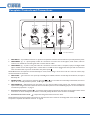
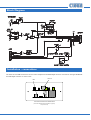
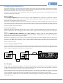
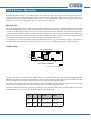
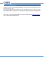
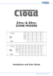
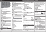
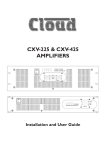
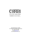
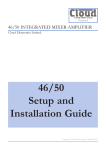
LM-2 Series Remote Mic/Line Mixer/Control Modules MIC LEVEL MIC LEVEL 5 6 MUSIC LEVEL 5 7 4 9 2 10 1 0 7 4 8 3 6 2 8 2 4 2 10 1 0 6 7 2 1 0 8 2 1 0 LINE INPUT MIC LEVEL 6 5 9 2 10 1 0 6 7 4 8 3 4 5 6 1 9 2 3 2 8 3 10 1 0 MIC PRIORITY 5 6 LINE INPUT 7 4 8 2 10 9 3 MIC INPUT 0 MUSIC LEVEL 7 4 10 1 LM-2D LM-2 5 9 2 MIC INPUT 10 7 8 3 9 3 6 4 7 4 LINE INPUT 6 5 6 5 10 MIC PRIORITY 5 4 1 9 3 3 2 8 0 MIC PRIORITY MIC INPUT 9 10 1 5 4 8 3 6 MUSIC LEVEL 7 4 5 1 9 3 6 5 3 1 0 LM-2A Installation Guide LM-2 Installation Guide v1.0 1 Contents Introduction..................................................................................................................................... 3 Mounting - mechanical................................................................................................................... 3 Faceplate Controls and Connections............................................................................................ 4 Block Diagram................................................................................................................................. 5 Installation - connections............................................................................................................... 5 Configuring the Facility Port........................................................................................................................................ 7 Connecting multiple LM-2s.......................................................................................................................................... 7 Local inputs................................................................................................................................................................... 7 Remote controls.......................................................................................................................................................... 8 LM-2 Priority Operation................................................................................................................ 9 Mic priority:................................................................................................................................................................... 9 Full priority:................................................................................................................................................................... 9 Power considerations.................................................................................................................... 10 2 LM-2 Installation Guide v1.0 Introduction The LM-2 is a remote module for use with the following Cloud products: • Z4MK3 and Z8MK3 Zone Mixers • 46-120 and 46-120MEDIA Zone Mixing Amplifiers It cannot be used with any other Cloud product. NOTE: Unless specifically stated otherwise, all references to “LM-2” in this Installation Guide can be taken to apply to all LM-2 mechanical and cosmetic variants. The LM-2 module combines the functions of a remote input connection plate, local audio mixer and a remote control for the host unit’s background music. Inputs for both a microphone and a stereo line signal (for a local music source) are provided, with individual level controls. The stereo channels are summed to mono, and then mixed with the mic input. The remote control facilities are equivalent to those on a Cloud RSL-6 remote control module, and allow selection of background music source and level control for the host’s Zone to which the LM-2 is connected. (Note that the 46-120 and 46-120MEDIA have a single Facility Port, for Zone 1 only.) The LM-2 is connected to the host unit’s Facility Port by a single screened Cat 5 cable with RJ45 connectors. A link connector is provided to permit multiple LM-2s to be installed in the same Zone. Mounting - mechanical LM-2 (UK version) The Cloud LM-2 fits a standard UK-style dual-gang electrical back box. The box used should have a depth of at least 35 mm. LM-2A (US version) The Cloud LM-2A fits a standard US dual-gang electrical ‘J’ box in vertical orientation. The box used should have a depth of at least 1¼”. LM-2D (German/Austrian version) The Cloud LM-2D fits a DIN-standard double-gang back box (requiring 2 x 68 mm dia cut-outs), of the type used in various countries including Germany and Austria. The box used should have a depth of at least 35 mm. LM-2 Installation Guide v1.0 3 Faceplate Controls and Connections 4 5 MIC LEVEL 5 6 5 9 2 7 4 5 6 1 9 2 10 1 0 3 2 8 3 10 1 6 4 8 3 7 MUSIC LEVEL 7 4 6 0 MIC PRIORITY 5 6 7 4 8 9 3 2 MIC INPUT 1 LINE INPUT 2 10 1 3 0 8 LM-2 UK version illustrated 1. MIC INPUT – 3-pin XLR3F connector for dynamic microphones. Note that the LM-2 does not provide phantom power. 2. LINE INPUT (a) – 2 x phono (RCA) sockets for connection of sources such as CD players, audio mixers, radio mic receivers, etc; suitable for line level signals with a nominal level of 0 dBu. 3. LINE INPUT (b) – 3-pole 3.5 mm jack socket for connection of sources such as computers, laptops and digital media players; suitable for line level signals with a nominal level of +8 dBu. A source plugged into this input will be summed to mono and mixed with any source connected to the phono inputs 2 . NOTE: Both stereo line inputs are summed internally to mono; hence, if using a mono source such as a radio mic receiver, only one channel need be connected. 4. MIC LEVEL – gain control for mic input. Up to 60 dB gain is available; with the control fully anti-clockwise, the input is effectively ‘off’. 5. MUSIC LEVEL – gain control for whichever line input ( 2 or 3 ) is in use.With the control fully anticlockwise, the source will be ‘off’; in the fully clockwise position, 10 dB of gain is provided. 6. MIC PRIORITY – default function for this button is to give the microphone input priority over both the module’s line input and the background music selected at the host unit.This operation can be modified by jumpers on the rear PCBs. See “LM-2 Priority Operation” on page 9. 7. BACKGROUND MUSIC SOURCE – six-position switch selecting which of the host unit’s six Line Inputs will be routed to the Zone to whose Facility Port the LM-2 is connected (usually the Zone where the LM-2 is installed). 8. BACKGROUND MUSIC LEVEL – adjusts the background music level in the Zone. NOTE: Switches and internal jumpers will need to be set in the host unit in order for the background music controls to operate as required. See “Remote controls” on page 8. 4 LM-2 Installation Guide v1.0 7 and 8 Block Diagram RJ45 RJ45 Installation - connections The LM-2 has two PCBs mounted on the rear of the faceplate.The OUTPUT RJ45 connector is located on the upper PCB while the LINK RJ45 connector is on the lower: LINK OUTPUT LOCATION OF REAR RJ45 CONNECTORS (‘DIN’ version illustrated. Sketch simplified; only primary components shown) LM-2 Installation Guide v1.0 5 The LM-2’s OUTPUT connector should be connected to the host unit’s FACILITY PORT for the Zone in which it is installed* with screened Cat 5 cable and shielded RJ45 plugs. 100 m max Connect to OUTPUT socket Connect to FACILITY PORT Screened Cat 5 cable OUTPUT LINK LM-2 (UK version illustrated) The maximum total Cat 5 cable length should not exceed 100 m. If further modules are being “linked” together (see below), this figure applies to the overall cable run from the host unit to the “furthest” module in the chain. IMPORTANT: Because the cables carry low-level audio, only screened Cat 5 should be used, the foil screen of the cable being bonded to the metal screening can of the plugs. If an LM-2 is being installed in very close proximity to the host unit, it may be possible to use ready-made screened Cat 5 “patch” cables of short length. In all other situations, shielded RJ45 plugs should be crimped onto the installed screened Cat 5 cable using the pinout shown below. PIN USE Cat 5 CORE 1 Audio ‘cold’ phase (-) White + Orange 2 Audio ‘hot’ phase (+) Orange 3 Priority VCA control White + Green 4 +15 V Blue 5 0V White + Blue 6 -15 V Green 7 Music level control (0 to 10 V) White + Brown 8 Music source select control (0 to 10 V) Brown Screen for system music controls Connector shell SCN * There is no reason why the module cannot be connected to the Facility Port of a Zone other than that in which it is installed – though this is likely to be an unusual installation scenario. 6 LM-2 Installation Guide v1.0 Configuring the Facility Port The mic and line inputs on the LM-2 module will be available in the Zone as soon as the module is connected to the host unit’s Facility Port for that Zone. The volume of the mic and line inputs will be determined solely by the level controls on the LM-2 faceplate and unaffected by any of the host unit’s front panel controls. In order for the remote control section (background music source and level controls to operate correctly), the host unit must be set for remote control operation. Z4MK3 and Z8MK3: Set the MUSIC CONTROL button on the host unit’s rear panel to REMOTE (in) for the Zone in use. The button is adjacent to the REMOTE SOURCE + LEVEL connector immediately above the FACILITY PORT. This will disable the host unit’s front panel music source and level controls for the Zone. Sometimes it is desirable to permit remote control of music level but keep music source selectable only on the host unit. In this case, internal jumper J1 on the sub-board for the Zone in use should be moved from ‘SW’ to ‘FR’. This will render the LM-2’s music source switch inoperative, and return source selection to the front panel. See the Z4MK3/Z8MK3 Installation and User Guide for full details and jumper locations. 46-120 and 46-120MEDIA: These units only have a single Facility Port, for Zone 1. Thus the LM-2 can only be installed in Zone 1. (If the LM-2 needs to be added to a different Zone in an existing system, this restriction may be simply overcome by swapping outputs and renaming the Zones.) Set the two REMOTE MUSIC CONTROL buttons (LEV and SRC) for ZONE 1 on the rear panel to REMOTE (in). The buttons are immediately below the 4 x 3-pin REMOTE CONTROL PANEL CONNECTORS. This will disable the host unit’s front panel music source and level controls for Zone 1. Sometimes it is desirable to permit remote control of music level but keep music source selectable only on the host unit. In this case, set the SRC button for ZONE 1 back to FRONT PANEL (out). This will render the LM-2’s music source switch inoperative, and return source selection to the front panel. See the 46-120/46-120MEDIA’s Installation and User Guide for full details and jumper locations. Connecting multiple LM-2s Two or more LM-2s may be installed in the same Zone by employing the LINK connector on the lower rear PCB. The primary purpose of this feature is so that microphones and music sources may be connected into the audio system at different locations within a single Zone (typically one of large area or complex layout). Connect to OUTPUT socket Connect to OUTPUT socket OUTPUT Screened Cat 5 cable OUTPUT LINK Connect to FACILITY PORT LINK Connect to LINK socket LM-2 (UK version illustrated) Screened Cat 5 cable Local inputs When modules are “daisy-chained” together in this way, the audio signals from each module are summed together to produce a single mono feed to the host unit. Thus two (or more) microphones may be connected within a zone and either or both used as wished, with individual mic level controls at their respective modules. An internal gating circuit on each module automatically “disconnects” any chained modules which are not in use, to minimise noise contribution. Should this the gate function not be required for any reason, it may be disabled by linking two solder pads on the lower PCB - see page 8. (Remove the lower PCB from the faceplate before attempting to make this link.) This also applies to multiple music sources simultaneously connected (though the possibility of resulting cacophony makes this a less likely scenario!) LM-2 Installation Guide v1.0 7 LM-2 LOWER PCB PHONOS XLR DISABLE LINK GATE LINK THESE TWO PADS NOTE: Users should be aware when using simultaneous microphone and/or music sources from multiple linked modules that the operation of the LM-2’s Priority function may become unpredictable, and if the function is enabled, one microphone may disable another, for example. We recommend that the Priority function is not used under these circumstances. Remote controls When modules are linked, only one may act as the remote control for each of the host unit’s background music functions: source and level. The MUSIC SOURCE and MUSIC LEVEL controls 7 and 8 (see “Faceplate Controls and Connections” on page 4) on all but one of the linked modules must be disabled. This is done by moving jumpers J1 and/or J3 on the upper PCB as required. J4 LM-2 UPPER PCB J1 J3 LOCATION OF JUMPERS Link indicates default jumper setting The default setting for J1 and J3 is LOCAL; this enables both the faceplate background music source and level controls. Set both jumpers to LINK to “pass” the remote control functions to the LM-2 connected at the LINK connected. Note that the two functions – background music source selection and background music level – may be disabled individually, so that one LM-2 in a Zone could control the music source and another the music volume. FUNCTION LOCAL LINK J1 Source select Local LM-2 selects music source Linked LM-2 music source J3 Level Local LM-2 music volume Linked LM-2 sets music volume sets selects Note that it is also possible to “daisy-chain” standard Cloud RL-1 and RSL-6 remote control plates to the LINK connector. This would be useful if additional background music control points were required in the Zone, but not additional system inputs. Please refer to the Technical Notes section at www.cloud.co.uk for further information on this topic. 8 LM-2 Installation Guide v1.0 LM-2 Priority Operation If the MIC PRIORITY button on the LM-2 faceplate is not pressed, mic and/or line signals connected at the module will be routed to the Zone to whose Facility Port the LM-2 is wired, and heard through the audio system at volumes which can be controlled from the MIC LEVEL and MUSIC LEVEL controls on the faceplate. These locally-connected signals will be mixed within the host unit with any background music currently selected for that zone. Mic priority: The LM-2’s Priority facility has two modes of operation, selected by jumpers on the upper rear PCB.The default mode operates thus: with MIC PRIORITY pressed, a signal at the microphone input will cause the line input signal connected at the same module to “duck” by 30 dB, giving the speaker priority over the music.The attack time (how quickly the music level drops when the mic is used) and release time (how quickly it recovers after the mic signal stops) are pre-set, and optimised for best audible results. The priority control signal is also sent to the host unit, where it additionally “ducks” whichever Line Input is currently selected in the Zone. Thus the LM-2 mic input has priority over both local and global music sources. It is important to note that any Priority functions set within the host unit – e.g., Line 6 Priority or Paging – will operate as normal. However, if Line 6 Priority is selected and active, the Line 6 source will still be ducked by the LM-2’s Mic Priority. Full priority: LM-2 UPPER PCB J1 J3 LINK LOCAL LM-2 MIC MIC MAX LINK LOCAL J2 J4 LOCATION OF JUMPERS Link indicates default jumper setting If jumpers J2 and J4 are moved from their default settings to the alternative setting, Priority operation changes. When MIC PRIORITY is pressed, the module’s summed output is used to derive the priority control signal that is sent back to the host unit, and the signal is at the voltage required by the host unit to fully mute the background music. The result is that a signal at either the LM-2’s mic input or line input will fully mute the selected Line Input at the host unit, and thus any source connected at the LM-2 will take full priority over the Zone’s background music. As with the default mode, any priority functions set within the host unit itself will still operate normally, though if Line 6 priority is selected and active, the Line 6 source will be overridden by the LM-2 Priority. MODE J2 J4 PRIORITY SOURCE BACKGROUND MUSIC Mic Priority MIC MIC LM-2 mic input 30 dB ducking Full Priority LM-2 MAX Sum of LM-2 mic input and line input Full muting LM-2 Installation Guide v1.0 9 Power considerations The LM-2 is powered from the host unit’s FACILITY PORT via the Cat 5 connection. The LM-2 consumes 12 mA of current from the host unit’s power supply. In the majority of installations, the host unit will have ample spare current capacity to power one or more LM-2s. However, installers should note that this may not be case in a very large system with multiple remote modules in several Zones. If there is any doubt about the power capability, please refer to the host unit’s Installation and User Guide where full details of power supply ratings can be found. Should you have any questions concerning the installation and connection of the LM-2, please visit www.cloud.co.uk/resources, where you will find additional technical information. 10 LM-2 Installation Guide v1.0 LM-2 Installation Guide v1.0 11 Cloud Electronics Limited 140 Staniforth Road Sheffield S9 3HF England Tel: +44 (0)114 244 7051 Fax: +44 (0)114 242 5462 email: [email protected] web: www.cloud.co.uk Cloud Electronics USA 2065 Sidewinder Drive, Suite 200, Park City, Utah 84060. United States of America. Toll Free: 0855 810 0161 Web: www.cloudusa.pro E-mail: [email protected]