1
11.14 Completion of the Installation
Check that all the gas and water connections on the manifold
have been tightened.
Undo the two screws and remove the connections cover panel.
Refer to Fig. 29.
Connect the mains supply lead to the appliance and secure the
cable clamp. Refer to Fig. 29.
Check that there is sufficient loose lead to allow the release of the
facia panel assembly.
Connect the earth lead. The earth lead of the mains supply must
be longer than the live and neutral leads.
Fit the facia mounted clock or programmer. Full instructions are
sent with the control. Refer to Fig. 30.
Connect any external controls ensuring that the leads pass through
the appropriate cable clamp. Refer to Section 11 and Fig. 31.
Test for gas soundness as described in BS6891.
If the appliance is not to be commissioned immediately, replace the
connection cover panel and the cabinet.
Check that the gas and electricity services have been turned off.
If Z is between 425 - 725mm it is not necessary to cut the
terminal assembly or use a second extension duct as the length
can be set telescopically.
If Z is greater than 725mm then two extension duct assemblies will
be required, the first assembly being cut to length as plain tubes.
If more than two extension ducts are needed in any section to
achieve the required length then the final section of the
assembly must not be less than 275mm without cutting the
terminal assembly.
NOTE: The flue duct of the final extension must be 30mm longer
than the air duct.
Each section must be connected to the previous section of the
flue bend by fixing the flue ducts together and then similarly
fixing the air ducts which engage the elbows.
Fit the assembly as described in Section 11.9, 11.10 as
appropriate.
Make good the internal and external brickwork or rendering.
11.13 Vertical Adapter for Horizontal Flues
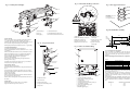
An adapter is available for an initial short section of vertical flue.
Refer to Fig. 28.
Measure and cut the flue as described in Section 11.12.
The first, vertical, section (equivalent to dimension X) is
measured from the top of the boiler casing. Cut the vertical
section of the extension duct to 167mm less than the measured
distance. Do not remove the socketed ends.
The minimum measured distance is 167mm.
Seal the air duct to the spigot using silicone sealant.
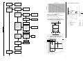
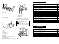
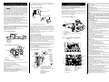
Fig. 27 - Elbow to Flue Turret
Assembly.
4
5
7
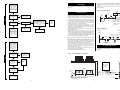
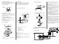
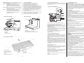
Fig. 50. Combustion Chamber Insulation.
3
2
6
1
2
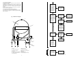
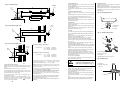
Fig. 29. Facia connections
2
1. Pump
2. Pressure gauge connection
3. System connection hose
4. Air vent fixing clip
5. Air vent cartridge
6. By-pass pipe
7. 0-Ring
3
2
120mm
1
4
3
7 Relief Valve
Remove the clip-on facia cover, cabinet, unscrew the single screw
and lower the facia onto the lower support lugs.
Check that the appliance has been fully drained.
Disconnect the relief valve discharge pipe .
Pull down the fixing clip and pull out the relief valve. Refer to Fig. 17.
NOTE: The clip does not need to be fully removed.
1
1. Combustion chamber assembly
2. Rear insulation panel
3. Side insulation panel
4. Front insulation panel (fixed to combustion chamber
front cover)
100mm
*5mm
Flue Turret
Fig. 52. Pressure Gauge connection.
5 Combustion Chamber Insulation.
Remove inner casing door and combustion chamber cover.
Slide the damaged insulation panel from the appliance
Rear
Remove heat exchanger. Refer to Fig 61.
Remove the side insulation panels.
Slide the rear insulation forward and up to remove.
Replacement is the reverse of removal. Refer to Fig 50.
Bend
*When connecting to an elbow the flue duct must be
5mm longer than the air duct.
4
5
14
ST2
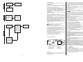
Fig. 28 Vertical Adapter.
13
6
Series
connection
point
Flue Duct
Air Duct
7
11
9
8
1. Controls connector
cover
2. Controls connector
cover fixing screws (2)
3. Facia control panel
4. Earth connection (tags)
Adapter
5. Earth connection
(screws)
6. Cable clamp
7. Fuse F1 2A (slow)
8. Cable clamps
(pump and fan)
Flue Spigot
18
12
10
8
9. ST15 Pump
10. ST1 Fan
11. Fuse F2 1.25A (slow)
12. Commissioning switch
(gas valve mode switch)
13. Internal controls
connectors
14. Mains and external
controls connectors
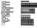
Fig. 54. Water flow turbine.
6 Pressure Gauge
Remove the clip-on facia cover, cabinet, unscrew the single screw
and lower the facia panel onto the lower support lugs. Refer to
Fig. 39 and 40. Check that the appliance has been fully drained.
Slide the captive clip upwards and remove the pressure-sensing
head. Refer to Fig. 52.
Unclip the gauge head from its mounting bracket and remove.
Refer to Fig. 51.
Check the condition of the O-ring at the pressure capillary head
before fitting the replacement gauge.
1
3
2
Fig. 51. Pressure Gauge head
1
1. Flow turbine
2. Clips (2)
3. O-ring
4. Filter/Flow restrictor
4
2
4
24i White 8 l/min
28i Blue 10 l/min
3
8 Flow Turbine/ Filter/ Restrictor
Drain the DHW circuit as described at the start of Section 16.
Remove the clip-on facia cover, cabinet, unscrew the single screw
and lower the facia panel onto the lower support lugs.
Separate the turbine in-line electrical connector.
Remove the two fixing clips and withdraw the turbine assembly.
1. Pump
2. Pressure gauge capillary
3. Pressure gauge head
4. Mounting bracket
27