1
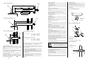
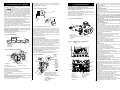
TEST G
Is the boiler in a very
cold environment (less
than 5°C)?
No
2.3 Electrical Supply
230V - 50Hz. Load 152 watts. External fuse 3A, Internal fuses F1
- 2A, F2 - 1.25A (20mm).
Replace control board.
Note: A damp board
could cause this fault.
2.4 Gas Supply
The appliances require a maximum of 3.17 m3/h of natural gas
(G20) or 1.23 m3/h of propane (G31) [28i] or 2.74 m3/h of natural
gas (G20) or 1.06 m3/h of propane (G31) [24i].
The installation and the connection of the gas supply to the appliance
must be in accordance with BS6891 in GB and, IS813 in Eire.
The meter or regulator should deliver a dynamic pressure of 20 mbar
(G20) or 37mbar (G31) at the appliance, which is equivalent to about
18.5 mbar or 36 mbar at the gas valve inlet pressure test point.
Yes
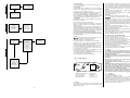
TEST H
Boiler is running in
“Autofrost stat” mode.
See Section 17.
Hot water
temperature always
too hot during a
demand (not
regulating).
The Central Heating Temperature control knob provides for the
selection of domestic hot water only (turned fully anti-clockwise)
or central heating and domestic hot water (turned clockwise).
A facia mounted programmer is provided as an optional extra. A
remote mounted programmer may be connected to the
appliance.
There is provision for the connection of a mains voltage room
thermostat and/or a frost thermostat.
The electronic controls prevent rapid cycling of the appliance in
the central heating mode.
2.8 System
These appliances are suitable for sealed systems only.
All dirt must be flushed from the system before
connecting the appliance. The system can be pre-piped and
flushed before the appliance is fitted. If a system cleaner has
been used then it must be completely removed before initially
filling the system and adding, where necessary, an inhibitor.
The connections in the system must withstand an operating pressure of
upto 3 bar.
Radiator valves must conform to BS2767: 10:1977.
Table 3 gives the pump head available for the system and the
required temperature differential.
A drain cock must be fitted to the lowest point and an air vent to
the highest point of the system.
In Eire the requirements in respect of the system given in the
current Irish Building Regulations must be followed and further
guidance is available in Annex M of IS813.
2.5 Installation
The appliance is suitable for indoor installation only and for use
with a sealed system only.
Do not place anything on top of the appliance.
This is a room sealed appliance and a separate combustion air
supply is not required in any room or compartment in which the
appliance is fitted.
If the appliance is fitted in a cupboard or a compartment is built
around it after installation, then the structure must conform to the
appropriate standards. However, because of the low casing losses,
there is no need for cooling ventilation openings in the compartment
provided that the specified clearances are maintained.
The spaces specified for servicing must be maintained.(See Table 8).
There is space for the service pipes to pass through the side channels at
the back of the appliance.
Hot water sensor
could be off or poorly
fixed to pipe.
Repair or replace.
2.9 Showers, Bidets, Taps and Mixing Valves
All taps and mixing valves must be suitable for the available
mains pressure and temperatures up to 65oC.
It may be necessary to fit a pressure reducing valve.
Hot and cold mains fed water can be supplied to overrim bidets
but is subject to local water company requirements.
The flow of water from individual outlets varies on all mains fed
systems that are not fitted with flow balancing valves.
Thermostatically controlled or pressure equalising shower valves
give extra comfort and protection.
If a pressure equalising valve is fitted then the domestic hot
water temperature should be set to maximum.
2.6 Flue
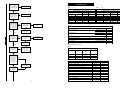
Does the problem
occur in CH mode
only?
TEST I
Yes
No
Problem occurs in the
HW mode only.
Check flow sensor:
with boiler cool,
slowly open a HW tap.
Does the boiler ignite
with a flow of about
3 l/min?
(Check using a
measuring jug and
stop watch i.e 500ml
in 10 sec.
No
Turbine sticking or
seized.
Replace the turbine.
Yes
Standard Multi-Directional Horizontal Flue Kit can be
adjusted from 425mm to 725mm without cutting.
The minimum length is 265 mm with cutting.
Extended flue lengths up to a maximum of 3m are available.
Optional 45° and 90° flue bend kits are available NOTE: When
using flue bends the maximum flue length is reduced.
If access to the flue terminal will be a problem then a kit is available
to enable the horizontal flue to be fitted from inside the house.
Do not allow the flue terminal fitted to the outside wall to
become obstructed or damaged.
A terminal guard, Type K2, GC 393 553, is available from Tower
Flue Components, Vale Rise, Tonbridge, TN9 1TB.
A vertical flue system is available with a maximum height of
4.1m including the flue terminal assembly.
Refer to the separate vertical flue system booklet .
2.10 Safety
The appliance must not be operated with the inner casing
cover removed or without being full of water and pressurised.
The gas and electricity supplies must be turned off before
working on the appliance.
The appliance can only be electrically isolated externally.
Temperature monitoring controls are fitted to prevent
overheating.
Automatic frost protection is provided together with
automatic pump seizure protection.
The gas valve solenoids are automatically checked for gas
soundness.
IMPORTANT: Where back-flow prevention devices, including
water meters, are fitted the expansion of hot water into cold
water main can be prevented. This can result in a pressure
build-up that may cause damage to the boiler and household
devices such as showers, washing machines etc.
In these cases we recommend that a mini-expansion vessel
be fitted adjacent to the boiler in the cold water inlet pipe.
The domestic hot water circuit should be in copper pipe.
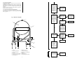
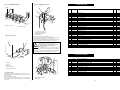
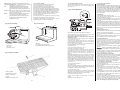
Fig. 1. Facia controls
It is not possible to
easily isolate the fault.
The most likely causes
are control board (fail),
heat exchanger
(blocked) or
gas valve (sticking).
6
3
5
4
1
2
2.11 Operation
2.11.1 Central Heating:
A demand for heat will ignite the burner.
It will operate at minimum pressure for 19 seconds before
increasing to the maximum pressure over a period of 1 minute
and then automatically match the system requirements. At the
end of the demand the burner will go out, the pump will
continue to run for up to 3 minutes and the fan for 35 seconds.
There is an anti-cycle time of 3 minutes.
1. Central Heating temperature 4. Optional timer
control On/Off knob
5. Fault indicator and
2. System pressure gauge
reset button
3. Burner ON indicator
6. User guide location
2.7 Controls
The electronic control system and gas valve modulate the heat
input in response to the domestic hot water temperature and the
central heating setting.
42
3