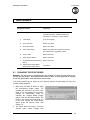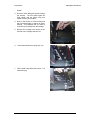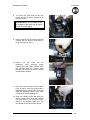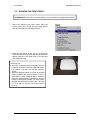
1
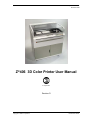
Z406 System User Manual November 2002 Z®406 3D Color Printer User Manual Z Corporation Revision D Copyright © 2002 Z Corporation Part Number 09504 Z Corporation Z406 System User Manual Table of Contents: 1 YOUR Z406 SYSTEM .................................................................................................. 6 1.1 2 3 INTRODUCTION ................................................................................................... 6 1.1.1 OVERVIEW...................................................................................................................6 1.1.2 HOW IT WORKS ..........................................................................................................7 1.2 THE PARTS OF THE Z406 3D PRINTER........................................................... 10 1.3 THE PARTS ON THE PRINTER ASSEMBLY AND GANTRY ............................ 11 1.4 Z406 SYSTEM COMPONENTS .......................................................................... 12 1.4.1 STEP 1: IMPORTING THE FILE.................................................................................13 1.4.2 STEP 2: PREPARING THE 3D PRINTER ..................................................................13 1.4.3 STEP 3: PRINTING THE PART..................................................................................13 PREPARING THE Z406 SYSTEM TO PRINT ........................................................... 14 2.1 HARDWARE CONTROLS ................................................................................... 14 2.2 PREPARING THE 3D PRINTER ......................................................................... 15 2.2.1 FILLING THE FEED BOX WITH POWDER ................................................................16 2.2.2 CLEANING THE SERVICE STATION ........................................................................18 2.2.3 CHECKING FLUID LEVELS .......................................................................................20 2.2.4 CHECKING POWDER OVERFLOW BIN....................................................................21 2.2.5 PUTTING THE MACHINE ONLINE ............................................................................22 SETTING UP THE BUILD.......................................................................................... 23 3.1 OPEN OR IMPORT THE FILE............................................................................. 23 3.2 ORIENTING THE PART ...................................................................................... 24 3.2.1 PART CONTAINING AN OPENING OR HOLLOW AREA ..........................................24 3.2.2 PART CONTAINING OVERHANGS ...........................................................................24 3.3 CHECKING BUILD SETTINGS ........................................................................... 25 3.3.1 3.4 4 PRINTING THE BUILD ........................................................................................ 27 POST PROCESSING THE PART.............................................................................. 28 4.1 REMOVING THE FINISHED PART..................................................................... 28 4.2 DEPOWDERING THE PART............................................................................... 29 4.3 DRYING THE PART ............................................................................................ 30 4.3.1 STARCH AND PLASTER PARTS ..............................................................................30 4.3.2 ZCAST PARTS ...........................................................................................................30 4.4 2 POWDER SETTINGS .................................................................................................26 INFILTRATING THE PART.................................................................................. 31 Z Corporation Service (781)852-5050/(887)88-ZCORP Z406 System User Manual 4.4.1 5 6 Z Corporation USING Z CORP. RECOMMENDED RESIN ...............................................................31 ADVANCED USER FEATURES ................................................................................32 5.1 ORIENTATION FOR SPEED ...............................................................................32 5.2 ORIENTATION FOR STRENGTH .......................................................................32 5.3 ORIENTATION TO PREVENT WARPING ..........................................................32 MAINTENANCE .........................................................................................................33 6.1 CHANGING THE PRINT HEADS.........................................................................33 6.2 ALIGNING THE PRINT HEADS...........................................................................36 6.3 COLOR ALIGNMENT...........................................................................................42 6.4 FLUSHING THE BINDER ....................................................................................44 6.5 OILING THE FAST AXIS......................................................................................44 6.6 OILING THE SNOWPLOWS (FOR NON-ZCAST POWDER USERS)................45 6.7 CLEAN UNDER THE GANTRY ...........................................................................45 6.8 OIL SLOW AXIS FRONT RAIL (FOR ZCAST POWDER USERS)......................46 6.9 REPLACING THE SCRAPER BLADE (FOR ZCAST POWDER USERS) ..........47 6.10 CHANGING THE BINDER SUPPLY ....................................................................48 6.11 CHANGING MATERIAL SYSTEM .......................................................................49 7 8 9 TROUBLESHOOTING ...............................................................................................54 7.1 THE BINDER SOLUTION IS BEING APPLIED IN ERRATIC STRIPES .............54 7.2 THE SOFTWARE FREEZES DURING USE ......................................................54 7.3 THIN PLANAR PARTS ARE WARPING 7.4 NOTHING HAPPENS WHEN I TRY TO PRINT 7.5 MY STARCH-BASED PARTS ARE UNUSUALLY “CAKEY” ...............................55 7.6 PARTS ARE UNUSUALLY WEAK OR CRUMBLY..............................................55 7.7 PRINTER LOOKS LIKE IT IS PRINTING, BUT IS NOT LAYING DOWN BINDER55 ..........................................................54 ..............................................54 Z406 SYSTEM DETAILS............................................................................................56 8.1 DESCRIPTION OF REAR I/O PANEL .................................................................56 8.2 SYMBOLS USED .................................................................................................57 8.3 SYSTEM SPECIFICATIONS................................................................................58 8.4 MATERIAL STORAGE PRECAUTIONS..............................................................59 8.5 ERROR CODES...................................................................................................59 INDEX .........................................................................................................................66 www.zcorp-users.com 3 Z Corporation Z406 System User Manual Table of Figures Figure 1. The Printing Process ................................................................................................. 7 Figure 2: The Z406 System Shelling and Infrastructure Features............................................ 8 Figure 3: Illustration of Z406 System Print Orientations .......................................................... 9 Figure 4: The Z406 3D Printer ................................................................................................ 10 Figure 5: Gantry and Printer Assembly................................................................................... 11 Figure 6: Z406 System Components ...................................................................................... 12 4 Z Corporation Service (781)852-5050/(887)88-ZCORP Z406 System User Manual Z Corporation Use of Equipment The Equipment was manufactured under patents licensed to Z Corp. to be used for the fabrication of appearance models and prototypes. Other uses may be restricted; contact Z Corporation for further information. The Equipment is designed to be used by design engineers and other professionals in the production of early-stage 3D appearance models and prototypes. The Equipment is not to be used to produce, either directly or indirectly, medical or other products that may require precise dimensions or tolerances to ensure the safe and effective operation of such products. You agree to indemnify, defend and hold Z Corporation and its officers, directors and employees harmless from and against any and all claims, losses, damages, costs and expenses resulting from any use of the Equipment other than for the production of early-stage appearance models and prototypes. If you have purchased all relevant casting-specific products as recommended by Z Corp. (castingspecific service contract, hardware, software, and consumables), as well as a casting license, then you are authorized to utilize the Equipment to fabricate molds for casting. www.zcorp-users.com 5 Z Corporation Z406 System User Manual 1 YOUR Z406 SYSTEM 1.1 1.1.1 INTRODUCTION OVERVIEW This Z406 3D Color Printer Manual will speed you along the path towards quickly and inexpensively building parts. The manual contains the following sections: 1. Introduction. This section will give you an overview of the principles behind the Z406 System, familiarize you with the terminology we will use to describe the Z406 System and introduce you to some of the features of this manual. This section concludes with an outline of the three quick and easy steps to printing parts. 2. Preparing the Z406 System to Print. This section will guide you through putting powder, binder solution and washer fluid in the Z406 3D Printer, and preparing the system to print a part. 3. Setting Up The Build. This section gives you a brief overview of how to set up a build on the ZPrint Software. For more information about the softwre and its features, please refer to the ZPrint User Manual. 4. Printing the Part. This section describes the steps of actually printing the part. 5. Post Processing a Part. This section guides you through removing your printed part, removing any excess powder and infiltrating the part with resin to improve strength and finish. 6. Advanced User Features. This section will help you get the maximum performance out of your Z406 System. 7. Maintenance. This section contains instructions for keeping your Z406 3D Printer in proper condition through regular preventative maintenance. 8. Troubleshooting. This section offers some troubleshooting tips. 9. Z406 System Details. This section contains system specifications about the Z406 3D Printer. 10. Index. 6 Z Corporation Service (781)852-5050/(887)88-ZCORP Z406 System User Manual 1.1.2 Z Corporation HOW IT WORKS The Z406 System is based on the Massachusetts Institute of Technology’s patented 3DP (3D Printing) technology. The software first converts a three-dimensional design built using 3D CAD (and saved in VRML or STL format) into cross-sections or slices that can be between 0.003” – 0.009” thick. The Z406 3D Printer then prints these cross-sections one after another from the bottom of part to the top. Inside the Z406 3D Printer there are two pistons (see Figure 1.) The feed piston is represented in the diagrams below on the left and is shown in the ‘down’ position filled with powder. The build piston is the piston on the right, shown below in the ‘up’ position. Also represented in the diagrams is the roller (drawn as a circle) and the print assembly (drawn as a square.) On the Z406 Printer, the roller and the print assembly are mounted together on the gantry which moves horizontally across the build area. To begin the 3D printing process, the Z406 System first spreads a layer of zp series powder in the same thickness as the cross section to be printed. The Z406 print heads then apply a binder solution to the powder causing the powder particles to bind to one another and to the printed crosssection one level below. The feed piston comes up one layer and the build piston drops one layer. The Z406 System then spreads a new layer of powder and repeats the process, and in a short time the entire part is printed. Step 1: As the gantry traverses left to right, the roller collects powder. Step 2: The roller spreads a thin layer of powder over the build piston. Step 4: As the gantry traverses right to left, the print head prints the part cross-section. Step 3: The roller discharges excess powder down the powder overflow chute. Step 5: The feed piston moves up one layer, the build piston moves down one layer, and the process is repeated. Figure 1. The Printing Process www.zcorp-users.com 7 Z Corporation Z406 System User Manual The Z406 System employs several techniques to quickly build parts. First, binder solution is applied in a higher concentration around the edges of the part, creating a strong “shell” around the exterior of the part. Within parts, the Z406 3D Printer builds an infrastructure by printing strong scaffolding within part walls with a higher concentration of binder solution. The remaining interior areas are printed with a lower saturation, which gives them stability, but prevents over-saturation, which can lead to part distortion of the part. Interior infrastructure printed at a higher saturation Other interior areas printed at lower saturation Exterior walls printed at higher Figure 2: The Z406 System Shelling and Infrastructure Features After printing, the part is removed from the powder bed, depowdered and dried. The part can then be infiltrated with wax, epoxy, or other materials to increase strength and durability. You will have the part in your hands and can start improving your design within the same day—usually within hours. Because the powder layers support the structures being printed above, the Z406 System prints parts without support structures and can print parts with complex geometries that are impossible for other systems. There are several important characteristics of the Z406 System that will help you print the best parts for your intended purpose. Part Placement. The software will automatically place the parts within the build box to maximize build speed, the most important criteria for the majority of our users. The software positions the parts with the smallest dimension in the z (vertical) axis. In addition to part placement, the following other characteristics should be considered. Strength. The ultimate strength of the part will be somewhat affected by its orientation within the print box. The part will be strongest along the y-axis and the x-axis and less strong along the z-axis. This is because the cross sections are printed in continuous strips along the y or the “fast” axis (the print heads direction of travel), bands across the x or the “slow” axis (the gantry direction of travel) and laminated layers along the z-axis. (See figure 3 below.) This discussion only applies to untreated parts; once parts are infiltrated, they uniformly take on the strength characteristics of the infiltrating material. 8 Z Corporation Service (781)852-5050/(887)88-ZCORP Z406 System User Manual Z Corporation z-axis Less Strong x-axis Strong Strong y-axis Figure 3: Illustration of Z406 System Print Orientations Accuracy. The accuracy of the system depends on the materials you choose. You can employ the anisotropic scaling feature in the software to adjust for expected shrinkage and bring your parts into true scale. More information on anisotropic scaling factors are found in Section 3.31, Powder Settings.. www.zcorp-users.com 9 Z Corporation 1.2 Z406 System User Manual THE PARTS OF THE Z406 3D PRINTER Power Switch (Hold down for 6-8 seconds to shut off Printer.) Feed Box Light Overflow Chute Print Heads Service Station Build Box Control Panel Overflow Bin WasteBottle Primary Color Binder Clear Binder Bottle Washer Fluid Figure 4: The Z406 3D Printer 10 Z Corporation Service (781)852-5050/(887)88-ZCORP Z406 System User Manual 1.3 Z Corporation THE PARTS ON THE PRINTER ASSEMBLY AND GANTRY Head Clamp Cover Spreader Roller Carriage Cover Print Heads Gantry Head Release Lever Head Clamp Latch Figure 5: Gantry and Printer Assembly www.zcorp-users.com 11 Z Corporation 1.4 Z406 System User Manual Z406 SYSTEM COMPONENTS ZD4i Depowdering Station Z406 3D Printer ZW4 Automated Waxer Figure 6: Z406 System Components 12 Z Corporation Service (781)852-5050/(887)88-ZCORP Z406 System User Manual Z Corporation Printing a Part Overview Printing a part using the Z406 3D Printer is fast, easy, clean and fully compatible with an office environment. This manual will show tips on how to print the most challenging parts, but for most purposes, printing a part is as simple as 1-2-3. 1.4.1 STEP 1: IMPORTING THE FILE OPENING A FILE – Upon launching the ZPrint Software, you will be presented with the ‘Open’ dialog box. Select the file you wish to print. The software allows you to open a variety of monochrome and color file formats including STL, PLY, SFX, VRML (WRL), BLD, ZEC, ZBD and ZCP files. The software also allows you to move and scale your part, or pick a color for monochrome (STL) files before printing. 1.4.2 STEP 2: PREPARING THE 3D PRINTER Carefully following the steps outlined in Chapter 2, you can prepare the 3D printer in less than ten minutes. You will put powder in the feed piston, and ensure fluid levels are correct and that the powder overflow bin is empty. 1.4.3 STEP 3: PRINTING THE PART The Z406 3D Printer prints most parts in minutes and prints even the largest parts in a few hours. You may then remove the part, depowder any excess powder and, if desired, dry and infiltrate the part with wax or other materials to give the part the desired strength and finish. The post-processing phase takes less than ten minutes for small parts and only an hour or so for the most massive parts. Once you have completed these steps you are ready to start using parts to improve design, communicate with other departments and reduce the time it takes you to get new products to market. www.zcorp-users.com 13 Z Corporation Z406 System User Manual 2 PREPARING THE Z406 SYSTEM TO PRINT 2.1 HARDWARE CONTROLS The front control panel on the Z406 3D Printer has the following features: PLEASE NOTE: When the system is online, all buttons except the Online button are disabled. LCD Panel. Displays the current status of the Z406 3D Printer. Feed Up/Down Buttons. Allows user to raise or lower the piston in the Feed Box. A light tap raises or lowers one layer thickness; holding down causes continuous motion. Online Button. Enables and disables printer communication. 14 Build Up/Down Buttons. Allows users to raise or lower the Build Box. A light tap raises or lowers one layer of thickness; holding down causes continuous motion. Spread Button. This button allows you to move the gantry from left to right. Moving the gantry from left to right allows you to spread powder over the build box. Holding down this button will result in continuous spreading of powder. Z Corporation Service (781)852-5050/(887)88-ZCORP Z406 System User Manual 2.2 Z Corporation PREPARING THE 3D PRINTER If the machine is off, switch it on by pressing and releasing the Power ON/OFF Switch. The red power light and yellow error light will turn on. Then the Gantry will move slowly as it orients itself. We recommend that you leave the machine on at all times—in sleep mode the machine will exercise the print heads during periods of inactivity to prevent clogging. 1. Wait for the green Online light indicating that the power-up procedure has completed. The warm up process should take between 60 and 90 seconds. 2. Take machine offline by pressing and releasing the Online Button. 3. Open the Top Cover to gain access to the build area. Technical Tip LEAVE THE MACHINE ON! This allows the printer to perform a periodic self maintenance. www.zcorp-users.com 15 Z Corporation 2.2.1 Z406 System User Manual FILLING THE FEED BOX WITH POWDER 1. Press and hold the Feed Down button until the piston reaches the bottom of the Feed Box. The piston will stop when it reaches the bottom. The Front Display will read “F: 100% B: 100%” 2. Carefully scoop powder from the bucket and place in the feed piston. 3. Grip the Powder Scoop and using a stabbing motion, insert it repeatedly a few inches into the loose powder to compact it. Continue for about 10-15 seconds until the powder feels firm. 4. For each powder bag added to the Feed Box, repeat steps 2, 3 and 4. 5. When Feed Box is filled to top, take the Tamper and slowly press it onto the powder surface. Be careful not to “slap” the Tamper into the Feed Box, which will produce airborne particles. About 10-15 pounds of force will give a smooth, flat, and compact surface. Failure to firmly pack Feed Box will affect part quality. 16 Z Corporation Service (781)852-5050/(887)88-ZCORP Z406 System User Manual Z Corporation 6. Vacuum up any powder spilled on the Top Deck. 7. Spread the gantry so that it is above the feed piston. Press and hold the Feed Up Button until the surface of the powder is even with the Top Deck. 8. Raise the build piston until it is approximately one inch from the top. Pour powder into the build piston and tamp down until the powder is even. 9. Raise the build piston until the level of powder is approximately an eighth of an inch above the Top Deck. 10. Press and hold the Spread Button until a uniform bed of powder is formed in the Build Box. Make sure powder is even throughout the Build Box. WARNING: Use only powder supplied by Z Corporation. Use of any other material may impact the performance and/or safety of your Z406 System and will void warranty of equipment. Technical Tip Keep powder containers closed when not in use to keep powder dry. Scoop powder carefully to minimize airborne powder. Make sure that you carefully vacuum up excess powder. It only takes a minute, and the tidier the machine is, the less often it will need maintenance! Carefully read the Material Safety Data Sheet for powder before use. www.zcorp-users.com 17 Z Corporation 2.2.2 Z406 System User Manual CLEANING THE SERVICE STATION Squeegee Print Head Parking Caps Nozzl e Figure 9: Service Station Detail The Service Station cleans the array of the print heads during printing. The Service Station should be cleaned after every build. This should remove any deposits of powder. Make sure Parking Caps are dry before beginning the build. 18 Z Corporation Service (781)852-5050/(887)88-ZCORP Z406 System User Manual Z Corporation To clean the Service Station: 1. Move the gantry to the left of the top deck by pressing the ‘Spread’ button. 2. Lift the Top Cover. 3. Manually lift up the metal plate covering the service station. 4. Squirt distilled water onto the squeegee and wipe clean with the small brush provided with your Z406 3D Printer until all debris is removed. 5. Squirt the distilled water onto the parking cups and wipe clean with the small brush until all debris is removed. 6. Use a paper towel to soak up any standing water in the parking caps. www.zcorp-users.com 19 Z Corporation Z406 System User Manual 7. Squirt distilled water on the nozzles. Use the brush to clean off any debris. 8. When finished, replace the service station cover. 9. Close the Top Cover. 10. Return the gantry ‘Spread’ button. 2.2.3 by pressing the CHECKING FLUID LEVELS 1. Open the front cabinet doors. 2. Check the binder bottles and waste bottle. If the clear binder bottle and zc3 wash fluid are half full or empty, refill them. If the waste bottle is half full or more, empty it out. Waste should be treated in accordance with local regulations. Binder Solution Color Binder Solution Cleaning Solution Waste 3. Refill the primary color binder before every build. Pull out the color binder rack. 20 Z Corporation Service (781)852-5050/(887)88-ZCORP Z406 System User Manual 4. Unscrew and remove primary color binder bottle. Z Corporation the 5. Fill the bottle up with binder. Replace binder bottle in the proper order – cyan, magenta, yellow (from front to back). WARNING: Do not recycle waste solution. The waste is contaminated with powder and use of this waste in the Z406 3D Printer will clog the fluid system. Use only binder supplied by Z Corporation. Use of any other material may impact the performance and safety of your Z406 System and will void warranty. 2.2.4 CHECKING POWDER OVERFLOW BIN 1. Check the Overflow Bin at the right side of the machine. Slide the Overflow Bin out and check the level of powder. If the powder is more than half way full, empty the Bin before proceeding. www.zcorp-users.com 21 Z Corporation Z406 System User Manual 2. Use the vacuum to clean off the Filter found above the Overflow Bin. 3. Slide the Bin back into place. Make sure it is pushed all the way in. 2.2.5 PUTTING THE MACHINE ONLINE Press the ‘Online’ button. The green ‘Online’ Indicator Light will illuminate. The Z406 3D Printer is now ready to print. Technical Tip Keep the Machine Clean! Make sure that you have enough powder to complete the build. It is wise to always begin a build with a full feed box. CHECK THE OVERFLOW BIN! If the overflow bin becomes full, powder will back up through the system and cause errors with your printer. CHECK FLUID LEVELS! Make sure you have enough fluid to complete the build. Make sure the waste bottle is empty. Keep your Z406 3D Printer as clean as possible. The cleaner it is, the better it will function. Carefully read the MSDS for binder and wash fluid before use. 22 Z Corporation Service (781)852-5050/(887)88-ZCORP Z406 System User Manual Z Corporation 3 SETTING UP THE BUILD This chapter will briefly explain how to set up the build, check the 3D Print Settings, and print. For more information about the features in the ZPrint Software, please refer to the ZPrint User Manual. PLEASE NOTE: If the ZPrint Software has not been installed, install the software. Instructions are located in Section 1.1 of the ZPrint User Manual. 3.1 OPEN OR IMPORT THE FILE 1. Open the ZPrint Software. The open dialog box will appear. 2. Choose the file you wish to open. 3. Click ‘Open’ or double-click the file. 4. Choose the dimensions and powder type you will be using. 5. Click ‘OK’. 6. The file will be brought into the software and sliced. If you would like to open additional files, choose the ‘Import’ option under the File menu. www.zcorp-users.com 23 Z Corporation 3.2 ORIENTING THE PART 3.2.1 PART CONTAINING AN OPENING OR HOLLOW AREA • If the part has an opening or is hollow, place the opening or hollow side up. This will allow for the removal of powder during the gross depowdering process. 3.2.2 Part with Opening Hollow Part PART CONTAINING OVERHANGS • Unsupported overhangs should be placed on the left hand-side and as close to the build plate as possible. The plaster powder, being extremely fine, is more fluid in the build. Placing a small solid piece underneath overhanging surfaces would reduce the movement of the overhang. • Cylindrical features will be more accurate when their axis is parallel to the z-axis. For example, if you were to print a bottle, the bottle would best be printed standing up, with the mouth of the bottle facing the top of the Printer. 24 Z406 System User Manual 2.0 1.4 Z Corporation Service (781)852-5050/(887)88-ZCORP Z406 System User Manual 3.3 Z Corporation CHECKING BUILD SETTINGS ALWAYS check build settings before printing: 1. Choose the ‘3D Print Setup’ option from the File menu (or toolbar). 2. Check that the selected printer, powder type, and powder settings for the build are correct. The software settings are the recommended values. 3. If the settings need to be changed, select ‘Override’. Press ‘OK’ to confirm. For more information on how to change the settings, please refer to the ZPrint User Manual. • It is also strongly recommended that slice viewing and collision detection (if more than one part is being printed) be used before beginning the build. These features are found under the View menu of the software. • Slice Viewing allows you to view the cross sections of the part to identify any slice errors. • Collision detection will scan through the slices and report the layer in which part overlapping is found. www.zcorp-users.com 25 Z Corporation 3.3.1 3.3.1.1 Z406 System User Manual POWDER SETTINGS Anisotropic Scaling Values Anisotropic scaling values scale the model to accommodate any shrinkage or expansion of the part either due to characteristics of the material system or infiltrant system. A scaling value of one (1) is equal to 100% of the part in a specific axis. If the part shrinks 1% in a certain axis, the correct anisotropic scaling value would be 1.01 in that axis. The ZPrint Software will display the recommended values for each powder type. The scaling factors may differ according to wall thickness and geometry of the part. A higher accuracy level may be obtained by measuring the part and adjusting anisotropic scaling values as needed. To obtain new anisotropic scaling factors that are part specific, print the part with scaling factors of one (1) in all axes. Once the part is completed, post-process the part. Measure the x-, y-, and z-axes. Divide the nominal value by the measured value. For example, if the printed part had a nominal value of 1 and had a measured value of 0.98, the scaling value would be 1.02. After calculating the anisotropic scaling values, input them into the software and reprint the part and follow the post-processing procedure. 1. Plaster Material System The plaster material system has been found to remain dimensionally accurate during printing and thus, the recommended anisotropic scaling values are one (1) in all axes. If the infiltrant system being used changes the accuracy of the part, please alter the values as needed. 2. Starch Material System The shrinkage found in the starch material system is proportional to the part geometry and the drying time of the part. The longer the part is left to dry, the larger the shrinkage value. The part is most stable in the x and y-axis and shrinks more in the z-axis. Thus, the anisotropic scaling factor of the z-axis will always be greater than the values for both the x- and y-axes. 3. ZCast Material System The ZCast material system has been found to remain dimensionally accurate during printing and thus, the recommended anisotropic scaling values are one (1) in all axes. 26 Z Corporation Service (781)852-5050/(887)88-ZCORP Z406 System User Manual Z Corporation 3.3.1.2 Saturation Values The saturation values determine how much binder is placed on the powder to print the part. The part is made up of two areas, the shell and the core, as described in Section 1.1.2, How It Works. Thus, there are two saturation values, one for the shell and core. In general, the shell saturation is higher than the core saturation. The ZPrint Software will display the recommended values for each powder type. 1. Plaster Material System The shell and core saturation values for the plaster material system are generally constant values, meaning that there is only one value for all geometry types. 2. Starch Material System The shell and core saturation values for the starch material system depend on part geometry. A thick walled part will have lower shell saturation than a thin walled part. Core saturation is dependent on the wall thickness of the part. The thinner the wall thickness the higher the core saturation; the thicker the wall thickness the lower the core saturation. The ZPrint Software will recommend shell and core saturation values based on the part geometry. If parts come out weak, increase the saturation values by 10%; if parts are difficult to depowder, decrease the saturation values by 10%. 3. ZCast Material System The shell and core saturation values for the ZCast material system are generally constant values, meaning that there is only one value for all geometry types. 3.4 PRINTING THE BUILD It is strongly recommended that the build settings be confirmed before printing. To check build settings, choose ‘3D Print Setup’ under the File menu or click on the icon located on the taskbar. After all build settings have been confirmed: 1. Choose ‘3D Print’ under the File menu. 2. A dialog box will appear asking that powder and fluid levels be checked. 3. Press ‘OK’ to confirm that these have been checked to begin the build. Once the build has begun, a dialog box will appear reporting the status of the build. www.zcorp-users.com 27 Z Corporation Z406 System User Manual 4 POST PROCESSING THE PART 4.1 REMOVING THE FINISHED PART After the build is complete, remove the finished parts from the build box as follows: 1. With starch-based parts, wait approximately ten to fifteen minutes to ensure that the uppermost layers of the part have had a chance to dry. With plaster-based parts, leave the part in the bed for approximately 30-60 minutes. With ZCast parts, leave parts in the bed for approximately 30-60 minutes. 2. Take the machine offline by pressing the Online Button. 3. Lift the Top Cover. 4. Vacuum off any powder on the deck. 5. Press the Feed Down button to lower the feed piston. 6. Place a tray on the top of the Feed area. 7. Take a moment to look at the computer screen and determine exactly where parts lie in the build box. 8. Without raising the build piston, begin vacuuming powder out of the build box. Hold the end of the hose on a 20° to 30° degree angle over the powder so the hose inlet is 1/4” to 3/8” above the surface of the powder. This generates enough of a draft to lift loose powder without damaging the parts. 9. Vacuum powder away from the buried parts, and clean powder out of the margins against the walls of the Build Box. 10. To gain access to the sides of the parts, raise the Build Piston by holding down the Build Up button. 11. Remove the part and place on the tray. The part is now ready to be depowdered. WARNING: When performing any vacuuming operation, use the vacuum provided as part of the Z406 System. Vacuuming powder can generate static electricity, and use of a non-grounded vacuum will create static charges, which may affect the operation of the Z406 System and harm the operator. 28 Z Corporation Service (781)852-5050/(887)88-ZCORP Z406 System User Manual 4.2 Z Corporation DEPOWDERING THE PART 1. Place parts inside depowdering unit. 2. Using the compressed air system included in the Depowdering Station, remove any excess powder that remains in any concave surfaces. Technical Tip The air pressure on your Depowdering Station is adjustable. For bulky parts, turn the air pressure up. For more delicate parts, turn the air pressure down. www.zcorp-users.com 29 Z Corporation 4.3 4.3.1 Z406 System User Manual DRYING THE PART STARCH AND PLASTER PARTS To infiltrate starch or plaster parts with wax, the parts must be hot and dry. Preheat part at 165 degrees Fahrenheit in the Automated Waxer or in a drying oven, remembering that drying time and part wall thickness are directly related. If the average wall thickness is ¼”, then the part should be in the drying oven for 30 minutes. If average wall thickness is ½” inch, the part should be in the drying oven for 45 minutes. Use the chart below as a guide. Average Wall Thickness Drying Time 1/8 inch 15 minutes 1/4 inch 30 minutes 1/2 inch 45 minutes 1 inch or greater 90 minutes For instructions on how to use the Waxer, please refer to the Waxer User Manual. 4.3.2 ZCAST PARTS ZCast parts need to be dried at 400oF (204oC) for 2-6 hours. Drying times will depend on the mass of the part(s) and oven temperature. The parts need to dry in an oven with an air temperature of 400oF (204oC). PLEASE NOTE: Mold preparation and metal pouring requires adequate ventilation to ensure that exposures to dust, particulates, fumes and vapors are controlled below occupational exposure limits. Ventilation designs need to meet each customer’s respective governmental health and safety requirements. A reference frequently used by U.S. firms to comply with OSHA regulations is the American Conference of Governmental Industrial Hygienists Industrial Ventilation Manual. 1. Properly dried ZCast parts will have a golden brown finish. 2. Depowder part again after drying to ensure that you have a clean mold. Raw ZCast Part 30 Dried ZCast Part Z Corporation Service (781)852-5050/(887)88-ZCORP Z406 System User Manual 4.4 Z Corporation INFILTRATING THE PART The parts can be infiltrated with a variety of materials to produce a range of material properties. As an early stage design tool, it may not be necessary to infiltrate the parts at all. If you wish to use the parts for focus groups or to send to vendors, you may wish to infiltrate with resin, a two-part epoxy or other material for greater durability and longer life. For information on other possible infiltration materials call us at Z Corporation, or visit our website at www.zcorp-users.com 4.4.1 USING Z CORP. RECOMMENDED RESIN 1. Read and understand the Safety Information on the resin container label. 2. Dry the part as outlined in Section 5.3, Drying the Part. 3. In a well-ventilated area, place the part on waxed paper or on another non-stick surface. 4. Apply a thin coat of resin to the entire part by gently squeezing the bottle and letting the resin drip onto the part. 5. Once the entire part is coated, let it dry for 45 minutes to one hour. To stop the part from sticking to the wax paper, pick it up and move it every ten minutes until dry. 6. Once the part is dry, it can be sanded to improve the surface finish (250 grit sandpaper works best). This operation should be performed while wearing a dust mask. 7. To further improve the surface finish, the part can be waxed. To wax a part infiltrated with resin the part must be heated at 165 degrees Fahrenheit for one to three minutes before waxing. PLEASE NOTE: Please carefully read the Material Safety Data Sheet for resin before use. www.zcorp-users.com 31 Z Corporation Z406 System User Manual 5 ADVANCED USER FEATURES 5.1 ORIENTATION FOR SPEED Parts oriented with their largest dimension along the y or “fast” axis (print heads direction of travel), next longest along the x or “slow” axis (gantry direction of travel) and shortest dimension along the zaxis will print the fastest. Because speed is the most important feature for the majority of our customers, the software will automatically position parts with the shortest dimension along the z-axis. 5.2 ORIENTATION FOR STRENGTH In Section 1.1.2, How it Works, we explain that part features that lie in the x-y plane will be stronger than those aligned along the z-axis. If a part has a particularly delicate feature, especially one shaped like a thin rod, you might find aligning that feature in the x-y plane to be most successful. 5.3 ORIENTATION TO PREVENT WARPING Very thin planar part features printed in starch-based powder may warp if they dry unevenly or are excessively heated. (This problem will not occur with plaster-based powder). Thin, planar features aligned along the z-axis will dry more evenly than those with thin planar features that lie flat along the top of the build box. Also, be careful when drying parts with thin planar features in the drying oven. We find that thoughtful positioning and limited drying time effectively control warping in starch-based powder. 32 Z Corporation Service (781)852-5050/(887)88-ZCORP Z406 System User Manual Z Corporation 6 MAINTENANCE Maintenance Action: 1. Change Print Heads Frequency: Every 30 Billion Pixels (each print head in monochrome mode), 15 Billion Pixels (each print head in color mode), or when needed 2. Flush Binder If not used regularly 3. Oil the Fast Axis Before every build 4. Oil the Snowplows Before every build 5. Clean Under Gantry Before every build when using starch powder; Every week when using plaster powder 6.1 5. Vacuum Filter Before each build 6. Clean Service Station Before each build 7. Oil Slow Axis Rail (ZCast Users ONLY) Before each build 8. Replacing the Scaper Blade (ZCast Powder Users ONLY) As needed CHANGING THE PRINT HEADS WARNING: Do NOT touch or contaminate the gold contacts on either the print heads or the carriage with your fingers. Avoid spilling binder on the contacts. If you do get binder or anything else on the gold contacts, clean them with an alcohol swab. If the print becomes faint or begins to print unevenly replace the print heads (Z Corp. part number 13524) as follows: 1. Make sure the Z406 3D Printer is using the monochrome binder supply. The software will alert you if you are in color mode. If you are operating in color mode, change to monochrome mode by choosing the ‘Change Binder Supply’ option under the 406 Service Menu. The binder in the system should be clear. If it is not clear, choose the ‘Flush Binder’ option under the Service menu. See Section 7.4. 2. The Printer should be Online. From the ‘Service’ menu, select ‘Change Print www.zcorp-users.com 33 Z Corporation Z406 System User Manual Heads’. 3. Press the ‘Start’ dialog box button to begin the process. The front panel lights will flash rapidly and the gantry and print heads will move into position. 4. Wait for the Printer to finish moving and the front panel lights to change to slowly blinking. This indicates that it is safe to remove the print heads from the carriage. 5. Remove the carriage cover screw on the left side of the carriage and lift cover. 6. Push head release lever away from you. 7. Lift the head clamp latch and unhook. Lift head clamp up. 34 Z Corporation Service (781)852-5050/(887)88-ZCORP Z406 System User Manual Z Corporation 8. To remove the print head, lift the blue handle and pull up gently. Repeat for all four print heads. PLEASE NOTE: All print heads should be changed at the same time to ensure proper print head logging. 9. Before inserting new print head, clean the contacts with an alcohol crush swab (Z Corp. part number 12073.) 10. Remove the print head from the packaging. After removing plastic covering from print heads contacts, clean the contacts with the alcohol swab provided. Let alcohol dry before inserting print head into carriage. 11. Insert the new print head and push down firmly on top to make sure print heads is seated properly in the carriage. Close and latch the printhead clamp. Push head release lever forward towards you. 12. Close the carriage cover and press the ‘Online’ button once. Once the machine has come back on line, press the ‘Done’ button on the software dialog box. The print heads will now need to be aligned. www.zcorp-users.com 35 Z Corporation 6.2 Z406 System User Manual ALIGNING THE PRINT HEADS PLEASE NOTE: After every print head change, you must perform the alignment procedure. 1. Select the ‘Service Print Head’ option under the Service menu. This will get the print heads started and verify that they are operating correctly. 2. Bring the build piston all the way up, open the top cover and place the alignment pad and any additional backing required in the build area, to the right and rear of the build area. Technical Tips – 3. • Use the Z Corporation alignment pads. They are bound on two sides so that the paper lays flatter. If the paper is not flat, you may get erroneous results. • When the alignment paper is too low on the Build Pallet, the pattern will become blurred. To print a sharp pattern, place additional pad or cardboard (from the alignment pad) underneath to raise the height of the alignment paper. For best results, the pad should be at the height of the Top Deck. If it is too high up, the roller will hit the pad and move it. 36 Z Corporation Service (781)852-5050/(887)88-ZCORP Z406 System User Manual Z Corporation 4. Close the Top Cover and put the Printer online. 5. Select the ‘Alignment’ option under the 406Service menu. 6. Click on ‘Print Test Pattern’ in the alignment dialog box. It will take a minute to initialize the Printer, send the pattern, and print. 7. After the alignment pattern has printed, lift the Top Cover, and carefully remove the top, printed sheet of the alignment pad. 8. For each print head to be aligned, there are two numbers to be chosen. To do this, look at the alignment pattern and decide which pattern looks best. www.zcorp-users.com 37 Z Corporation Z406 System User Manual These additional targets will be most even when the alignment is correct. Bull's eye targets, one for each head. When it looks well centered, the head is in alignment. F1, S1 etc. correspond to the entries in the dialog box. These reticules are for the slow axis. Notice how the lines are centered for the '0' choice. These reticules are for the fast axis. Notice how the lines are centered for the '0' choice. This area warms up the heads to get them printing evenly. It does not factor into the alignment. In this pattern, a properly aligned set has four longer lines with three shorter lines centered between them. Print head 0 is the reference, print heads 1 through 5 are aligned to print head 0. Each row is labeled at the left, F1 and S1 correspond to Fast1 and Slow1 on the dialog box and following. 38 Z Corporation Service (781)852-5050/(887)88-ZCORP Z406 System User Manual Z Corporation See the examples below for properly and improperly aligned reticules. Normal reticule patterns: Fast axis to the left Good fast axis reticule Fast axis to the right The three short lines are interleaved with the long lines. Examples of problem reticules: Slow axis too low Good slow axis reticule. Slow axis too high The three short lines are interleaved with the long lines. www.zcorp-users.com 39 Z Corporation Z406 System User Manual 9. Look up the numbers that are next to the best-aligned pattern as described above. 10. Choose ‘Edit Alignment’ alignment dialog box. in the Technical Tips – If you have printed problem reticules, and are not able to choose the best aligned pattern, choose ‘Set Defaults’ under the Edit Alignment option and continue alignment procedure. 11. Enter numbers for each row into the corresponding (fast and slow axis) boxes: F1 – Head 1, Fast S1 – Head 1, Slow F2 – Head 2, Fast S2 – Head 2, Slow F3 – Head 3, Fast S3 – Head 3, Slow 12. Click ‘OK’. The software will ask you to update the INI file. Click ‘OK’ to update the Printer’s configurations. 13. Repeat steps 2-11 on a clean sheet of alignment paper until all alignment reticles line up at 0. 14. Look at target drawings to confirm alignment of print heads. 40 Z Corporation Service (781)852-5050/(887)88-ZCORP Z406 System User Manual Z Corporation All targets are evenly spaced. All bull's eyes are centered. 15. Purge print heads after alignment process with clear binder. This will clear print heads of black ink and fill them will clear binder. The process should take about 10 minutes. The LCD will display ‘Online’ when the Printer has completed the purge process. 16. Press ‘Done’ to dismiss the dialog box. 17. Unpark the gantry to expose the Service Station. 18. Clean the Service Station of any HP ink residue as described in Section 2.2.2, Cleaning the Service Station. Clean the deck and fast axis rails. Oil the fast axis rails. Technical Tips – The first 50 layers of your part will have a tint of black HP ink. You may place a flat brick, such as the L&R BRICKS.BLD, under Sample files, under your part to purge all black ink before printing your part. www.zcorp-users.com 41 Z Corporation 6.3 Z406 System User Manual COLOR ALIGNMENT PLEASE NOTE: You will need to color align the print heads only if your standard alignment did not align your print heads properly. 1. Make sure you have run through the standard alignment, purged the print heads, and changed the binder supply to color mode. 2. Spread powder onto the build piston. 3. Choose ‘Color Alignment’ under the 406Service menu. 4. Choose to print the ‘Pattern’ to print two layers. 5. The pattern shown on the left will print. 42 Z Corporation Service (781)852-5050/(887)88-ZCORP Z406 System User Manual Z Corporation 6. Look at the left and right edges of the squares. Look for the least color fringing on the sides. For each color choose the corresponding square in the dialog box. In this case, the ‘0’ square would be chosen among the blue squares. Click ‘OK’ to go on to the vertical alignment selection. 7. Look at the top and bottom edges of the squares with the least color fringing. For each color choose the corresponding square in the dialog box. Then click ‘OK’. 8. Choose ‘Yes’ to update the printer’s alignment. The printer will restart. 9. Remove the printed pieces, spread powder onto the build piston, and repeat the color alignment procedure until all squares are aligned at ‘0’. PLEASE NOTE: You may also choose to print the ‘Part’ instead of the ‘Pattern’. The part will consist of 100 layers. Printing the part will make it easier to see the color fringing. Color fringing is characterized by a difference in color on the edges from the top of the colored square (red, green, and purple). The part with the best color match is the best choice. Enter the corresponding numbers into the software dialog box, update the ini file, and repeat if necessary. www.zcorp-users.com 43 Z Corporation 6.4 Z406 System User Manual FLUSHING THE BINDER 1. If the machine is not in daily use, binder should be flushed bi-weekly for one minute. This may be done by choosing the ‘Flush Binder’ option under the ‘Service’ menu in the ZPrint Software. 2. The LCD will display ‘Flushing Binder’ 3. When finished, press the ‘Online’ button. PLEASE NOTE: If machine will not be in use for more than a month, replace binder gallon and color binder bottles with bottles of distilled water and flush the system for 5 minutes. Then purge print heads for 2 minutes. Leave the distilled water in the machine. When ready to use the Z406 3D Printer, replace distilled water with Z Corp. binder and flush system for three minutes. 6.5 OILING THE FAST AXIS Apply oil (supplied in the tool kit) to the pillow blocks located on the fast axis rail of the Printer assembly. There is one located on the top rail and two located on the lower rail on the edge of the carriage. This procedure should be done before every build. Pillow Block Pillow Block on lower rail 44 Z Corporation Service (781)852-5050/(887)88-ZCORP Z406 System User Manual 6.6 Z Corporation OILING THE SNOWPLOWS (FOR NON-ZCAST POWDER USERS) Two snowplows are located between the roller on the gantry. Snowplows needs to be oiled before every build. To oil snowplows, squeeze a few drops of oil into the wicks on the snowplow. Wick 6.7 CLEAN UNDER THE GANTRY Powder will adhere to the bottom surface of the gantry due to moisture accumulation. This may cause poor surface finish and dragging of powder over the build area. To prevent dragging of powder over the build area, it is recommended that the bottom surface of the gantry be cleaned before every build for starch powder users and every week for plaster powder users. 1. Empty build piston of powder. 2. Put Printer offline and lower build piston. 3. Put Printer online. 4. Unpark the carriage so that the gantry can be manually moved. 5. Clean bottom surface with moist paper towel and dry. Move gantry manually if needed. www.zcorp-users.com 45 Z Corporation Z406 System User Manual 6. Press ‘OK’ on the Software dialog box to repark. 6.8 OIL SLOW AXIS FRONT RAIL (FOR ZCAST POWDER USERS) Oil the slow axis rail before every build to prevent slow axis errors. 1. Squeeze a few drops of oil on the wicks located on the front bearing. 46 Z Corporation Service (781)852-5050/(887)88-ZCORP Z406 System User Manual 6.9 Z Corporation REPLACING THE SCRAPER BLADE (FOR ZCAST POWDER USERS) The plastic scraper blade will eventually become worn and will need replacement. Five replacement blades are included in the kit. To replace the blade, peel off the old blade. Take a new blade, remove the adhesive covering, place blade diagonally into the scraper until it reaches the back and then place adhesive strip onto the scraper. www.zcorp-users.com 47 Z Corporation Z406 System User Manual 6.10 CHANGING THE BINDER SUPPLY Changing the binder supply allows you to change between monochrome and color mode. To change binder supplies, choose the ‘Change Binder Supply’ option under the 406Service Menu. The software will inform you when the printer is finished changing binder supplies. 48 Z Corporation Service (781)852-5050/(887)88-ZCORP Z406 System User Manual Z Corporation 6.11 CHANGING MATERIAL SYSTEM IF USING ZCAST POWDER Before using ZCast powder, a hardware upgrade (Z406 ZCast Kit, part number 06105) is needed to prevent damage to your Printer. The three hardware changes are new snowplows, scraper blade assembly, and front bearing. A build plate is also included to help remove parts from the build envelope. Please ensure that these hardware changes have been made before proceeding. Scraper Blade Assembly Snowplows Front Bearing For information on how to design a ZCast mold, read the ZCast Design Guide which can be found in the Applications section of the User Group Website at www.zcorp-users.com. To change material systems on your Z406 3D Printer, use the procedure below: 1. Remove all powder from the feed and build envelopes. Place powder in a sealed container to prevent absorption of moistureinto the powder. 2. To prevent material contamination vacuum off any remaining powder from the feed and build plates, and the top deck. www.zcorp-users.com 49 Z Corporation Z406 System User Manual 3. Remove the powder from the Overflow Bin and empty into a sealed container. 4. To prevent any material contamination, vacuum any remaining powder in the Overflow Bin. 5. Before replacing the Overflow Bin, vacuum the Overflow Bin track. Then replace the Overflow Bin. 50 Z Corporation Service (781)852-5050/(887)88-ZCORP Z406 System User Manual Z Corporation 6. Change binder solution (color and clear binder) if necessary. zb52 Binder 7. Change Printer mode from color to monochrome or monochrome to color if needed. 8. If you changed binder solution, flush binder for two minutes by choosing the ‘Flush Binder’ option under the Service menu. 9. For ZCast Powder users, remove scraper assembly if you are changing over to ZCast powder. Or attach scraper assembly if using plaster or starch material. Use the 3/32 hex key tool that accompanied the Z406 ZCast Kit. www.zcorp-users.com 51 Z Corporation Z406 System User Manual 10. Set up the Printer as described in section 2.2.2, Filling the Feed Box with Powder. Change Powder Type 11. Open or import your file into the ZPrint Software using version 6.0 or higher. 12. Open up the 3D Print Setup dialog box. 13. Change Powder type in ZPrint Software. 52 Z Corporation Service (781)852-5050/(887)88-ZCORP Z406 System User Manual Z Corporation Recommended Saturation Values 14. Override or approve shell and core saturation values and anisotropic scaling factors. Review bleed compensation values. 15. Then proceed to printing your part. www.zcorp-users.com 53 Z Corporation Z406 System User Manual 7 TROUBLESHOOTING 7.1 THE BINDER SOLUTION IS BEING APPLIED IN ERRATIC STRIPES If the binder appears to be applied in fragmented stripes, check the following: 1. Rinse the squeegee clear of any debris. 2. Make sure binder supply is full. If this does not correct the problem, your print heads may be worn out. Replace the print heads as outlined above in Section 6.1, Changing the Print Heads. 7.2 THE SOFTWARE FREEZES DURING USE Exit the software by pressing Ctrl_Alt_Delete and choosing End Task from the Task Manager, then restart the software. 7.3 THIN PLANAR PARTS ARE WARPING In general, warping is caused by uneven drying of parts. By adjusting print orientation and drying time, warping can be minimized. You can take steps to ensure that drying is occurring evenly by: 7.4 • Reorienting your part within the build box. If a thin planar surface of a part lies flat along the top of the build box, the broad exposed area may dry unevenly and bow towards the top. Reorient the part so that the thin planar surface lies perpendicular to the top of the build box. • Ensure that you are not over-drying the part. Reduce drying time to a minimum. Refer to the guide in Section 4.3 Drying the Parts to select a drying time. • Decreasing the layer thickness without proportionally changing the minimum and maximum saturations will over saturate the part causing it to warp and may also cause individual layers to curl during printing. NOTHING HAPPENS WHEN I TRY TO PRINT • Is the serial cord connected properly? • Remove the cord and carefully reinstall ensuring that you tighten the screws only after making sure that it is tight in the socket. Do NOT over tighten the screws. Are any of the lights on the control panel illuminated? If the error and power light come on but nothing happens after that, shut the machine off and turn it back on again. The machine should come online. But if it does not, please call the Service Department. 54 Z Corporation Service (781)852-5050/(887)88-ZCORP Z406 System User Manual 7.5 Z Corporation MY STARCH-BASED PARTS ARE UNUSUALLY “CAKEY” • Is the saturation too high? If your parts (especially bulky parts) are unusually difficult to depowder, too much moisture has moved from the part into the immediately surrounding powder. The first is that you may have the saturation levels set too high for this type of part. Using a lower maximum setting will fix this problem. • Was the part left in the bed too long? If the part is delicate and requires a higher maximum setting, it will be helpful to remove the part from the bed as soon as possible after the completion of the build. Using the delay timer feature will allow you to cause the build to end at a convenient time. 7.6 PARTS ARE UNUSUALLY WEAK OR CRUMBLY • Is the data file known to be without errors? If the *.stl file is not near perfect you will have problems printing the part. Open the file in the software and inspect it layer by layer to ensure there are no gaps and the part does not overlap other parts. • Is there enough binder in the feed bottles? When you start the build, a reminder box will pop up asking you to check if there is enough binder in the feed bottles. If you plan to start a large build make sure binder bottles are full. 7.7 PRINTER LOOKS LIKE IT IS PRINTING, BUT IS NOT LAYING DOWN BINDER As you begin printing, carefully watch the Z406 Printer to see if it is printing normally. It may be that the print heads are not properly seated in the carriage. This can cause a bad connection with the temperature sensor and the print heads will overheat. Prolonged periods of attempting to print without binder flow will damage the print head. You will need to replace the print heads. www.zcorp-users.com 55 Z Corporation Z406 System User Manual 8 Z406 SYSTEM DETAILS 8.1 DESCRIPTION OF REAR I/O PANEL Power Input Main Power Fuse Diagnostic Video Connector Diagnostic Keyboard Connector Serial Input Connection Serial Port Connection: This is an RS-232 serial port for data transfer to and from the ZPrint software. The Z406 System uses 115k baud and has the same pin out as a standard PC compatible computer. The connection to the Windows computer running the software requires a 9 pin to 9 pin null modem cable (also known as a ‘laplink’ cable). This cable is supplied with your Z406 System; if a replacement is required, order Z Corporation part #10267. Diagnostic Connections (Video and keyboard): These connections are used while servicing your Z406 System. Nothing should be connected to them in normal operation. The diagnostic video connection is standard VGA output video. The keyboard connection is PS/2 style compatible. 56 Z Corporation Service (781)852-5050/(887)88-ZCORP Z406 System User Manual 8.2 Z Corporation SYMBOLS USED The following symbols are used on the Z406 3D Printer: This is the international symbol for ‘standby power’. It is used on the Z406 3D Printer power switch. The Z406 3D Printer is partially powered as soon as you plug it in. The power switch is momentary contact and toggles the machine from idle mode to full power on mode. This is the international symbol for ‘warning’ or ‘caution’. It indicates the need to consult your manual for further information. This symbol is in two places on the Z406 3D Printer. 1. It is used on the rear, lower left to call your attention to the fact that only authorized personnel should open the Z406 3D Printer rear cover. None of the normal operation and maintenance procedures described in this manual require you to remove this cover. 2. It is used on the front cover next to the handle to call your attention to the fact that you should be careful not to drop the cover when closing it. Due to the weight of the cover and the force of the air springs, it is possible to pinch or strain a finger or hand if it were to get caught between the bottom of the cover and the front slow axis rail. www.zcorp-users.com 57 Z Corporation 8.3 Z406 System User Manual SYSTEM SPECIFICATIONS Z406 3D Printer Dimensions: 40” x 31” x 44” high (102cm x 79cm x 112cm high) Z406 3D Printer Weight: 470 lbs. (210 kg) Power Requirements and Operating Conditions at Site of Installation: • Power Requirements: 100-240, 4 amps • Operating Conditions: 68 to 85ºF, 20 to 60% Relative Humidity, non-condensing. Lithium Battery: Internal to the Z406 3D Printer is a lithium coin cell type battery. This may be any one of the following: Type: CR2032, either Maxell, Panasonic, Renata, Sanyo or Sony. PLEASE NOTE: This battery is not in a user accessible area and is not user replaceable. The expected lifetime of the battery is in excess of five years. Replacement will be handled by your Z Corporation customer service representative. FCC Notice: Note: this equipment has been tested and found to comply with the limits for a Class A digital device, pursuant to part 15 of the FCC rules. These limits are designed to provide reasonable protection against harmful interference when the equipment is operated in a commercial environment. This equipment generates, uses, and can radiate radio frequency energy and, if not installed and used in accordance with the instruction manual, may cause harmful interferance to radio communications. Operation of this equipment in a residential area is likely to cause harmful interference in which case the user will be required to correct the interference at his own expense. CENELEC Class A Warning: Note: this equipment has been tested and found to comply with the limits for a Class A digital device, pursuant to EN 55022. Class A devices are for office and light industrial environments, and are not generally suitable for home use. WARNING: This is a Class A product. In a domestic environment this product may cause radio interference in which case the user may be required to take adequate measures. 58 Z Corporation Service (781)852-5050/(887)88-ZCORP Z406 System User Manual 8.4 Z Corporation MATERIAL STORAGE PRECAUTIONS Carefully read the Material Safety Data Sheets (MSDS) before using any Z Corporation materials. 8.5 Material Storage Usage Powder Store powder on pallets in a cool, dry, ventilated area away from sources of heat, moisture, and incompatible materials. Keep containers tightly closed. Use of powder in environments with more than 30% relative humidity will affect powder performance. Binder and Wash Fluid Store in cool, dry place, away from sun. Keep tightly capped. Binder and Wash Fluid are NOT recyclable. Print Head Store in cool, dry place, away from sun. Keep tightly capped. Infiltrants Store in cool, dry place, away from sun. Keep tightly capped. For more information, visit the User Group Website at www.zcorp-users.com. ERROR CODES PLEASE NOTE: %d and %x are place holders for numbers corresponding either to print head number or a value. 100 0 Unknown head error 100 1 Can't turn on head 5 + 12 V 100 2 ROM read failed for head %d 100 3 I2C read failed for head %d 100 4 Head %d fire voltage failed 100 5 Head %d temperature too low 100 6 Head %d temperature too high 100 www.zcorp-users.com Head %d current too high 59 Z Corporation Z406 System User Manual 7 100 8 Head cover is open 100 9 Head %d fire voltage stuck 101 0 Invalid head temperature 110 0 SYSTEM: out of memory in thread %d 120 0 THREAD %d: can't create events 120 1 THREAD %d: can't initialize window system 120 2 THREAD %d: can't make window 120 3 THREAD %d: can't begin 120 4 THREAD %d: can't set priority 120 5 THREAD %d: illegal state 120 6 THREAD %d: refuses to stop 120 7 THREAD %d: refuses to die 130 0 QUEUE: out of memory 130 1 QUEUE: can't create event 130 2 QUEUE: received null pointer 140 0 KEYBOARD: can't add callback 140 1 KEYBOARD: can't create pipe 140 2 60 KEYBOARD: error writing pipe Z Corporation Service (781)852-5050/(887)88-ZCORP Z406 System User Manual Z Corporation 140 3 KEYBOARD: error reading pipe 150 0 KEYMAP: duplicate key %d 150 1 KEYMAP: bad key index %d 160 0 COM%d is not a valid port 160 1 COM%d: queue is too small 160 2 COM%d: ETS monitor is using port 160 3 COM%d: port already in use 160 4 COM%d: can't create event 160 5 COM%d: can't create thread 160 6 COM%d: can't set priority 160 7 COM%d: bad interrupt number 160 8 COM%d: IRQ already in use 160 9 COM%d: can't save interrupt vector 161 0 COM%d: can't set interrupt vector 161 1 COM%d: UART isn't 16550 compatible 161 2 COM%d: input queue overrun 170 0 STATUS: spurious read event 170 www.zcorp-users.com STATUS: bad thread index %d 61 Z Corporation Z406 System User Manual 1 170 2 STATUS: unknown system message %d 170 3 STATUS: invalid state %d 170 4 STATUS: unknown dispatch type %d 170 5 STATUS: message queue overrun 170 6 STATUS: can't save state 170 7 STATUS: can't restore state 170 8 STATUS: too many held layers 180 0 PACKETS: layer is too big 190 0 LAYERS: spurious read event 190 1 LAYERS: zlib InflateInit error %d 190 2 LAYERS: zlib Inflate error %d 190 3 LAYERS: zlib InflateEnd error %d 190 4 LAYERS: missing layer info packet 190 5 LAYERS: layer is too big 200 0 STRIPES: spurious read event 200 1 STRIPES: bad saturation 200 2 STRIPES: too many lines per stripe 200 3 62 STRIPES: line is too long Z Corporation Service (781)852-5050/(887)88-ZCORP Z406 System User Manual Z Corporation 200 4 STRIPES: bad print mode %d 200 5 STRIPES: bad line offset 210 0 UNRLE: bad layer number 210 1 UNRLE: bad print mode %d 220 0 BMOCO: LM629 does not respond 220 1 BMOCO: can't reset motor %d 230 0 MOVER: bad axis 230 1 MOVER: axis %d destination out of range 230 2 MOVER: axis %d move intersects no-fly zone 230 3 MOVER: axis %d excessive position error 230 4 MOVER: axis %d timed out completing move 230 5 MOVER: axis %d didn't settle 230 6 MOVER: axis %d can't change acceleration 240 0 REZERO: axis %d can't find end of travel 240 1 REZERO: axis %d already over sensor 240 2 REZERO: axis %d timed out looking for sensor 240 3 REZERO: axis %d couldn't find sensor 250 www.zcorp-users.com SHAKER: can't read layer info 63 Z Corporation Z406 System User Manual 0 250 1 SHAKER: bad layer number 260 0 HEAD: bad ROM format 270 0 DRAWSPAN: bad bit number 270 1 DRAWSPAN: bad print mode 280 0 TIGERCOM: serial write timeout 280 1 TIGERCOM: serial read timeout 290 0 TIGER: bad head index 300 0 SEQUENCER: bad FIFO size 300 1 SEQUENCER: can't create event 300 2 SEQUENCER: can't create thread 300 3 SEQUENCER: can't set priority 300 4 SEQUENCER: bad interrupt number 300 5 SEQUENCER: can't save interrupt vector 300 6 SEQUENCER: can't set interrupt vector 300 7 SEQUENCER: not enough data 300 8 SEQUENCER: overrun while waiting for HF 300 9 SEQUENCER: stalled while waiting for HF 301 0 64 SEQUENCER: sequence didn't finish, flags = %x Z Corporation Service (781)852-5050/(887)88-ZCORP Z406 System User Manual Z Corporation 301 1 SEQUENCER: error in DPC, flags = %x 301 2 SEQUENCER: spurious interrupt, flags = %x 301 3 SEQUENCER: timed out finishing swath, flags = %x 310 0 PRINTER: spurious read event 310 1 PRINTER: bad dispatch type %d 310 2 PRINTER: unknown message %d 310 3 PRINTER: message queue overrun 320 0 MONITOR: can't create waitable timer 320 1 MONITOR: can't set waitable timer 320 2 MONITOR: thread took too long 330 0 TIMER: unknown time unit 340 0 SWITCHES: switch %d is undefined 350 0 KEYPAD: object already exists 350 1 KEYPAD: can't create event 350 2 KEYPAD: object not initialized 360 0 BLINK: object already exists 360 1 BLINK: object not initialized 360 www.zcorp-users.com BLINK: object has too many users 65 Z Corporation Z406 System User Manual 2 360 3 BLINK: undefined sequence 370 0 LCD: object already exists 370 1 LCD: object not initialized 370 2 LCD: object has too many users 380 0 LOWLEVEL: can't find PCI card 380 1 LOWLEVEL: error opening FPGA file 380 2 LOWLEVEL: invalid FPGA load 380 3 LOWLEVEL: bad IRQ number 390 0 SOCKETS: can't initialize WinSock interface 390 1 SOCKETS: WinSock 1.1 not supported 400 0 TCP: can't create event 400 1 TCP: can't launch thread 400 2 TCP: thread refuses to die 400 3 TCP: error %d creating socket 400 4 TCP: error %d setting socket option 400 5 TCP: error %d binding socket 400 6 TCP: error %d listening on socket 400 7 66 TCP: error %d accepting socket Z Corporation Service (781)852-5050/(887)88-ZCORP Z406 System User Manual Z Corporation 400 8 TCP: error %d selecting socket 400 9 TCP: error %d getting received byte count 401 0 TCP: error %d receiving from socket 401 1 TCP: error %d looking up host by name 401 2 TCP: error %d connecting to host 401 3 TCP: error %d sending to socket 401 4 TCP: error %d setting non-blocking mode 410 0 UDP: error %d creating socket 410 1 UDP: error %d setting socket mode 410 2 UDP: error %d setting socket option 410 3 UDP: error %d binding socket 410 4 UDP: error %d looking up host by name 420 0 ZDNS: can't launch thread 420 1 ZDNS: thread refuses to die 430 0 NETWORK: can't find ethernet device 430 1 NETWORK: can't get device configuration 430 2 NETWORK: can't set device configuration 440 www.zcorp-users.com BITBUS: object already exists 67 Z Corporation Z406 System User Manual 0 440 1 BITBUS: object not initialized 440 2 BITBUS: readback error 450 0 FLUIDS: object already exists 450 1 FLUIDS: object not initialized 450 2 FLUIDS: unsupported pump rate 460 0 CARWASH: object already exists 460 1 CARWASH: object not initialized 460 2 CARWASH: carwash is stuck 460 3 CARWASH: can't finish squirt 470 0 BINDER: weak pressure from pump %d 470 1 BINDER: can't write plumbing state 470 2 68 BINDER: invalid plumbing type %d Z Corporation Service (781)852-5050/(887)88-ZCORP Z406 System User Manual Z Corporation 9 INDEX 3 3D Print, 27 Import, 23 Open, 23 Filling the Feed Box with Powder, 16 Flushing the Binder, 44 A Aligning the Print Heads. See Alignment Alignment, 36 Edit Alignment, 40 G Gantry Clean, 45 Anisotropic Scaling Values, 26 Plaster, 26 Starch, 26 ZCast Powder, 26 I Import File, 23 B Build, 23 Collision Detection, 25 Open File, 23 Part Orientation, 24 Printing, 27 Setting Up, 23 Build Settings, 25 M Massachusetts Institute of Technology, 7 Material Storage, 59 O Oiling the fast axis, 44 Oiling the Slow Axis Rail, 46 Open File, 23 3D Print Setup, 25 Override, 25 P C Changing the Material System, 49 Changing the Print heads, 33 Checking Fluid Levels, 20 Checking Powder Overflow Bin, 21 Cleaning the Service Station, 18 Collision Detection, 25 Color Alignment, 42 Control Panel, 14 D Part infiltration, 31 Part Orientation, 24 Circular Features, 24 Hollow Area, 24 Opening, 24 Overhangs, 24 Post Processing, 28 Powder Anisotropic Scaling Values, 26 Saturation Values, 27 Settings, 26 Powder Settings, 26 Print Heads Align, 36 Purge, 41 Depowdering Parts, 29 Drying Parts, 30 ZCast Powder, 30 Printing the Build, 27 E Error Codes, 59 R Refill the primary color binder, 20 Removing finished parts, 28 F File www.zcorp-users.com 69 Z Corporation Z406 System User Manual S Saturation Values, 27 Plaster, 27 Starch, 27 ZCast Powder, 27 Scraper Blade T Troubleshooting, 54 V Vacuum off the Filter, 22 Replacement, 47 Shelling, 8 Speed, 32 Strength, 32 Striping of Binder Solution, 54 System Specifications, 58 70 W Warping, 32, 54 Z Corporation Service (781)852-5050/(887)88-ZCORP