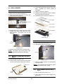
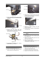
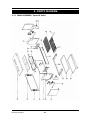
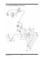
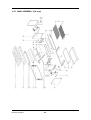
1
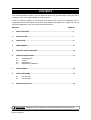
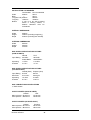
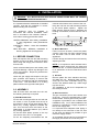
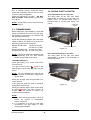
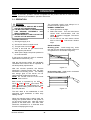
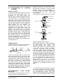
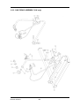
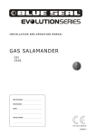
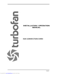
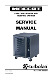
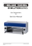
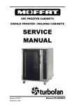
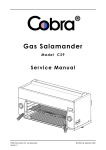
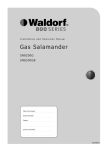
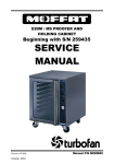
G91 GAS SALAMANDER
SERVICE MANUAL
Revision 3/F3547
-1-
WARNING: ALL INSTALLATION AND SERVICE REPAIR WORK MUST BE CARRIED
OUT BY QUALIFIED PERSONS ONLY.
Revision 3/F3547
-2-
CONTENTS
This manual is designed to take a more in depth look at the G91 gas salamander for the purpose of
making the units more understandable to service people.
There are settings explained in this manual that should never require to be adjusted, but for
completeness and those special cases where these settings are required to change, this manual
gives a full explanation as to how, and what effects will result.
SECTION
PAGE NO.
1.
SPECIFICATIONS ........................................................................................................ 5
2.
INSTALLATION ............................................................................................................ 7
3.
OPERATION ................................................................................................................. 9
4.
MAINTENANCE ............................................................................................................ 11
5.
TROUBLE SHOOTING GUIDE..................................................................................... 12
6.
SERVICE PROCEDURES............................................................................................. 14
6.1
6.2
6.3.
6.4
Fault Diagnosis
Access
Replacement
Adjustment / Calibration
7.
SPARE PARTS............................................................................................................. 20
8.
PARTS DIAGRAMS...................................................................................................... 21
8.1
8.2
9.
Non UK Units
UK Units Only
SERVICE CONTACTS .................................................................................................. 29
IMPORTANT: MAKING ALTERATIONS MAY VOID WARRANTIES AND APPROVALS.
Revision 3/F3547
-3-
Revision 3/F3547
-4-
1. SPECIFICATIONS
MODEL: G91
25
390
400
900
450
GAS ENTRY
5
SIDE
FRONT
PLAN
LEGEND
- Gas connection entry point - ½” BSP female
Dimensions shown in millimetres.
Revision 3/F3547
-5-
INSTALLATION CLEARANCES
Sides
Back
Top (Non UK)
Top (UK)
Bottom
Combustible Non-Combustible
250mm
25mm
—
25mm
600mm
600mm
1200mm
1200mm
If unit is to be wall mounted
above a cooking surface, a
600mm clearance must be
maintained.
OVERALL DIMENSIONS
Width
Height
Depth
900mm
420mm (Including trough tray)
540mm (Including rack handle)
INTERNAL DIMENSIONS
Width
Height
Depth
685mm
260mm
330mm
GAS SUPPLY SPECIFICATION OPTIONS
(NON UK UNITS)
Natural
LPG
Input Rating
26 MJ/hr
24650 Btu/hr
26 MJ/Hr
24650 Btu/hr
Operating
Pressure
1.0 kPa
4.0”w.c.
2.75 kPa
11”w.c.
GAS SUPPLY SPECIFICATION OPTIONS
(UK UNITS ONLY)
Input Rating
Natural (G20)
8.8 kW
Propane (G31)
8.8 kW
Gas Rate
0.84 m³/hr
0.63 kg/hr
Operating
Pressure
15 mbar
6.0”w.c.
37 mbar
14.8”w.c.
GAS CONNECTION SPECIFICATIONS
½” BSP female
INJECTOR SIZES (NON UK UNITS)
Natural
Main Injectors Ø1.65 mm
Pilot Injectors Ø0.46 mm
LPG
Ø1.00 mm
Ø0.25 mm
INJECTOR SIZES (UK UNITS ONLY)
Natural
Main Injectors Ø1.70 mm
Pilot Injectors Ø0.32 mm
Revision 3/F3547
Propane
Ø1.05 mm
Ø0.23 mm
-6-
2. INSTALLATION
WARNING: ALL INSTALLATION AND SERVICE REPAIR WORK MUST BE CARRIED
OUT BY QUALIFIED PERSONS ONLY.
nutserts at the bottom rear corners of the unit.
It is important that this salamander is installed
correctly, and that the operation is correct
before handing over to the user.
Hang the unit from the wall mounting bracket
by the black plastic spacers. Tighten the
black spacers securely and by adjusting the
levelling screws/bolts, ensure that the unit is
level.
This appliance must be installed in
accordance with national installation codes
and in accordance with relevant national /
local codes covering gas and fire health.
UNITED KINGDOM -Gas Safety (Installation
& Use) Regulations 1984 (Amendment
1990).
AUSTRALIA - AG601 - 1992, Gas Installation
Code.
NEW ZEALAND - NZS5261, Installation of
Burning Appliances and Equipment.
Figure 2.1 - Wall Mounting Bracket
b) Bench Mounted
Lift the unit onto its back, remove all plastic
covering, and screw four legs (optional extra)
into the hank nuts at each corner of the
appliances.
2.1 BEFORE CONNECTION
Each unit requires the rack and wall mounting
bracket or legs to be fitted. Remove all these
items along with tray(s) and instruction book
from the unit.
Lift onto its legs and ensure the unit is level by
adjusting the feet.
NOTE: It is important to leave at least 25mm
(1") of air space around both the sides and
rear of this unit. It is also important that there
is no obstruction to the air intake slots below
the unit.
Check all dismantled parts and hidden parts
for transit damage. Report any damage to the
carrier and supplier. Report any deficiencies
to your supplier.
c) All Units
Check the gas supply with respect to the gas
type, pressure and capacity to ensure that
they are in accordance with the requirements
of this oven. This information is on a rating
plate located on the right hand side panel.
Remove plastic film from stainless steel tray
and slide into unit. Branding plate models screw tap into black enamelled trough tray
and fit in the stainless steel tray. Slide trough
tray into the unit.
The installation of the rack is dependent on
the cooking function.
2.2 ASSEMBLY
With all loose items removed from the unit,
the following assembly is required:
d) Gas Connection
The gas connection point is at the bottom rear
of the unit. The unit is supplied with ½" BSP
female thread. Ensure pipe is firmly secured.
a) Wall Mounted Units
Fix the wall mounting bracket to the wall with
six screws, in such a position that the top of
the bracket is level and at least 945mm (38")
above any cooking appliance beneath the
unit. This will insure that the bottom of the
Salamander is at least 600mm (24”) above
any cooking appliance.
A regulator is provided for use on Natural Gas
installations only. On LP Gas installations the
pressure is controlled by a supply regulator at
the LP Gas supply tank.
It is important that adequate sized piping is
run directly to the connection of the unit, with
as few tees and elbows as possible to give
maximum supply volume.
Fit the two black plastic spacers to the top
rear corners of the unit. Do not tighten.
An accessible shut-off valve must be fitted on
the supply line before the connection joint.
Fit the two adjusting screws/bolts into the
Revision 3/F3547
-7-
Use a suitable jointing compound which
resists the breakdown from LP Gas on every
joint from supply to appliance.
2.4 RATING PLATE LOCATION
Check all connections for leaks. DO NOT
USE A FLAME. Make good any joints found
to be faulty.
The rating plate for the G91 and G91B
salamanders is located on the RH side front
bottom corner. An internal rating plate is
located inside on the RH side lower front
corner.
Units manufactured from July 2002.
NOTE: All gas fitting must be carried out by a
qualified person.
Rating plate
location
2.3 COMMISSIONING
Before leaving the new installation, check that
all the connections are correct and gas tight,
and that the unit functions in accordance with
the operating instructions.
Check the operating pressure at the test point
nipple located at the bottom rear of the unit.
Operating pressures are as follows:
Natural Gas (Not UK)
LP Gas
1.00 kPa (4.0” WG)
2.75 kPa (11.0” WG)
Internal Rating Plate
Figure 2.2
Natural Gas (G20 UK) 15 mbar (6.0" WG)
Propane Gas (G31 UK) 37 mbar (14.8" WG)
Units manufactured up to July 2002.
NOTE: It is intended that after installation and
commissioning, that the pilot burners
should remain alight continuously.
The rating plate for the G91 and G91B
salamanders is located on the underside of
the RH side panel.
LIGHTING THE PILOT
Check gas supply is on, check main burner
controls are off.
Turn gas control to PILOT . Push in and
hold the gas control knob, then light the pilot
burner.
NOTE: On new installations the pilot will not
ignite until all air has been purged from
the gas lines.
When pilot is alight, keep knob pressed in for
10-20 seconds.
Rating plate
location
If pilot goes out when the knob is released,
repeat above instructions.
Figure 2.3
When pilot remains alight, rotate control knob
to HIGH
position and allow burners to
remain on for 20 minutes to remove any
moisture from the plaques.
NOTE:
1) Make sure that the gas supply is shut off
before any service or maintenance
work is carried out.
2) It is important to re-light the pilot after
reconnecting the gas supply or after
changing gas cylinders.
Revision 3/F3547
-8-
3. OPERATION
NOTE: A full user’s operation manual is supplied with the product and can be used for further
referencing of installation, operation and service.
3.1 OPERATION
The removable tray(s) must always be in
position when the grill is in use.
NORMAL OPERATION
WARNING:
1) NO MATERIALS SHOULD BE PLACED
ON TOP OF THIS APPLIANCE.
2) THE BOTTOM TRAY OF SALAMANDER
CAN BECOME EXTREMELY HOT
WHILE OPERATING.
3) NEVER OBSTRUCT THE FLUE OUTLET
ON TOP OF THE APPLIANCE.
1. Check pilot burner is alight.
2. Select the burner. Turn the main burner
control knob anti-clockwise until the
HIGH
position is engaged. The burner
will now light.
3. To turn unit off, set main burner control
knob to PILOT . Pilot burner remains
alight.
LIGHTING THE PILOT
1) Check gas supply is on.
2) Check main burner controls are off.
3) Turn gas control to PILOT
RACK POSITION
.
Branding plate - Install trough tray under
rack with the rack sloping as below to allow oil
and grease to run off into the trough tray.
4) Push in and hold the gas control knob,
then light the pilot burner.
5) When pilot is alight, keep knob pressed in
for 10-20 seconds.
If pilot goes out when the knob is released,
repeat above instructions (1-5).
With the pilot burners alight, the individually
controlled main burners can be operated to
suit food quantity requirements.
Figure 3.1
After two minutes operation, the burners
should be a "glowing orange" with the outer
extremities not burning at all. The stability
and orange glow of the burner can be
observed better if lights are turned off.
NOTE: On non-UK units the inner burner
does not burn.
No branding plate - Install rack in horizontal
position as illustrated below.
Each burner is operated by an OFF
/
PILOT
/HIGH /LOW gas control. The
HIGH
position is recommended for most
grilling, cheese melting functions and LOW
for a reduced heat.
Figure 3.2
The rack fitted to the salamander is selfsupporting when withdrawn to allow easy
loading of food.
When the branding plate is being used, the
sloping rack position allows oil and grease to
run off into the trough tray. Note the closed
position of the drain valve. This drain valve
should be connected to a ½" diameter hose
for ease of emptying the trough.
Revision 3/F3547
-9-
3.2 EXPLANATION OF CONTROL
SYSTEM
SAFETY SYSTEM
The purpose of the safety system is to shut off
the flow of gas if the pilot flame goes out. It is
comprised
of
the
flame
itself,
the
thermocouple, and the flame failure gas valve.
Inside the body of the gas valve is an
electromagnet connected to a spring loaded
plunger. When the electromagnet is
energized, it holds the plunger in, allowing gas
to flow through the valve.
When the
electromagnet
is
de-energized, the plunger snaps to the closed
Thermocouple
The pilot flame is lit by holding in the gas
control knob, which in turn temporarily pushes
the plunger inside the safety valve open and
allows gas to flow through. Once the burner
is lit, the thermocouple will begin to generate
millivolts (after about 10 to 30 seconds of
being heated) and will energize the
electromagnet inside the gas valve. Once
energized the electromagnet holds the
plunger inside the gas valve in the open
position. The plunger has to have been
pushed all the way in for the electromagnet to
be able to hold it in place. If the burner flame
goes out for some reason, the thermocouple
will cool after about 10 to 30 seconds and
stop generating millivolts. The electromagnet
will then de-energize, and the plunger will
snap shut, cutting off the flow of gas.
Electromagnet
Plunger
Gas flow
Shaft
Knob
Gas flow
Detail of each component in the safety system
is explained below.
Plunger
Figure 3.4
position, stopping the flow of gas.
THERMOCOUPLE
Millivolts are provided to the electromagnet by
the thermocouple (not shown) which
generates millivolts when heated.
The
thermocouple screws into a fitting at the back
of the gas valve to make an electric
connection. By pressing in the gas control
knob, the plunger can be temporarily held
open while lighting. There's two reasons for
this; gas has to flow through the safety valve
to make it possible to light the pilot burner,
and secondly the plunger has to be pushed all
the way in for the electromagnet to hold it in.
I.e.; the electromagnet is strong enough to
hold the plunger in once there, but is not
strong enough to pull it in by itself.
Sometimes a problem with the flame not
staying lit after releasing the button can be
attributed to not pushing the plunger all the
way in.
The thermocouple is a device that generates
electricity when heat is applied to the tip.
Insulator
Nut
Internal
Wire
Conductor
Tip
Figure 3.3
The tip of the thermocouple is located in the
pilot burner flame, and the nut at the other
end of the thermocouple screws into the back
of the gas valve. Inside the copper tubing is a
wire which is joined at the tip but insulated
from the rest of the tubing. These two parts
(the copper tubing and wire) make up the
"wiring" for an electrical circuit. When these
two dissimilar metals, wire and tip, are heated
an electrical voltage is produced. This type of
thermocouple generates between 7 and 30
millivolts when heated in the pilot flame.
ELECTROMAGNETIC
GAS VALVE
FLAME
The Troubleshooting Guide (Section 5) should
be used to identify any incorrect operation.
On correct identification of the operating fault
the Troubleshooting Guide will make
reference to the corrective action required, or
refer to the Fault Diagnosis section and/or
FAILURE
The purpose of the safety valve is to shut off
the flow of gas if the pilot flame goes out.
Revision 3/F3547
-10-
4. MAINTENANCE
4.1 CLEANING
4.2 ROUTINE PROCEDURES
STAINLESS STEEL SURFACES
It is recommended that a service check is
conducted every six months.
Clean with detergent. Baked on deposits or
discolouration may require a good quality
stainless steel cleaner. Always apply cleaner
when the salamander is cool and rub in the
direction of the "grain".
1) Visual check of the pilot and main burners,
to see if correct size flame, and colour on
main burner.
2) Check the gas pressure with a manometer
(water gauge).
VITREOUS ENAMEL SURFACES
3) Check and clean inside control area,
making sure that all connections are
secure.
Do not use wire brushes, steel wool or other
abrasive material. Clean the interior regularly
with a good quality domestic oven cleaner.
Remove the rack and side racks from the
salamander - this allows easy cleaning of the
flat enamelled side walls. Leave the tray in to
collect all residue.
4) Check condition of the gas supply pipe,
regulator and fittings.
5) Check for gas leaks at all fittings inside
and outside the salamander.
6) Check gas control operation, smooth to
operate.
Regrease gas controls if
required (refer section 6.4.3).
CRUMB TRAY AND GREASE TROUGH
Empty and clean daily.
7) Check thermocouple operation, pilot
should hold quickly after lighting, replace
thermocouple if required.
GENERAL
To achieve the best results, cleaning must be
thorough, and all controls and mechanical
parts checked and adjusted periodically by a
competent serviceman. If any small faults
occur, have them attended to promptly.
Don't wait until they cause a complete
breakdown. It is recommended that a service
check is conducted every six months.
Revision 3/F3547
-11-
5. TROUBLE SHOOTING
WARNING: ALL INSTALLATION AND SERVICE REPAIR WORK MUST BE CARRIED
OUT BY QUALIFIED PERSONS ONLY.
FAULT
PILOT WON’T LIGHT
POSSIBLE CAUSE
Knob on gas control won’t go
fully in.
REMEDY
Remove obstruction. Correct
control panel mounting.
Replace gas control.
(Refer service section 6.3.10)
PILOT FLAME SMALL
PILOT GOES OUT WHEN
KNOB RELEASED
No gas supply.
Ensure gas is connected and
on (bottles not empty).
Gas pressure too low.
Check gas supply pressure.
(Refer specifications section)
Blocked pilot injector.
Clean or replace pilot injector.
(Refer service section 6.3.6/
6.3.7)
Gas pressure too low.
Check gas supply pressure.
(Refer specifications section)
Pilot injector restricted.
Clean or replace pilot injector.
(Refer service section 6.3.6)
Releasing knob before the
thermocouple is heated.
Hold control in for longer (30 s),
see if pilot will stay lit.
Pilot flame too small.
Correct fault.
(Refer fault:Pilot Flame Small)
PILOT GOES OUT WHEN
MAIN BURNER COMES ON
MAIN BURNERS WILL NOT
LIGHT
Thermocouple faulty.
(Refer fault diagnosis 6.1.1)
Replace thermocouple.
(Refer service section 6.3.8)
Gas magnet faulty.
(Refer fault diagnosis 6.1.1)
Replace gas magnet.
(Refer service section 6.3.11)
Incorrect gas pressure.
Check supply / adjust pressure.
(Refer specifications section)
Faulty gas control.
Replace gas control.
(Refer service section 6.3.10)
Wrong size or blocked injectors. Replace / clean injectors.
(Refer service section 6.3.3)
Small pilot flame.
Correct fault.
(Refer fault:Small Pilot Flame)
Revision 3/F3547
Incorrect supply pressure.
Check supply correct pressure.
Faulty gas control.
Replace gas control.
(Refer service section 6.3.10)
-12-
FAULT
POSSIBLE CAUSE
REMEDY
BURNER FLAME INCORRECT Incorrect supply pressure.
Check supply pressure.
COLOUR / FLAME NOT
STABLE
Pilot too small.
Correct fault.
(Refer fault: Pilot flame small)
BURNER POPPING / BLOW
BACK
Revision 3/F3547
Incorrect injector sizes.
Check injector sizes and
replace if necessary.
(Refer service section 6.3.3)
Injector blocked.
Clean injector.
(Refer service section 6.3.3)
Gas leak in burner plaque.
(Refer fault diagnosis 6.1.2)
Replace burner.
(Refer service section 6.3.1)
Gas leak at the salamander
side wall gasket.
Replace gasket.
-13-
6. SERVICE PROCEDURES
WARNING: ALL INSTALLATION AND SERVICE REPAIR WORK MUST BE CARRIED
OUT BY QUALIFIED PERSONS ONLY.
WARNING: ENSURE GAS SUPPLY IS SWITCHED OFF BEFORE SERVICING.
SECTION
6.1
FAULT DIAGNOSIS .............................................................................................................15
6.1.1
6.1.2
6.2
Side Panel ...........................................................................................................15
REPLACEMENT ...................................................................................................................16
6.3.1
6.3.2
6.3.3
6.3.4
6.3.5
6.3.6
6.3.7
6.3.8
6.3.9
6.3.10
6.3.11
6.4
Pilot Drops Out ....................................................................................................15
Burner Popping / Blow-back ................................................................................15
ACCESS .............................................................................................................................15
6.2.1
6.3
PAGE NO.
Main Burner .........................................................................................................16
Burner Plaque (Non UK Units Only) ....................................................................16
Main Injector ........................................................................................................16
Pilot Burner (Non UK Units Only) ........................................................................16
Pilot Burner (UK Units Only)................................................................................17
Pilot Injector (Non UK Units Only) .......................................................................17
Pilot Injector (UK Units Only) ...............................................................................17
Thermocouple (Non UK Units Only) ....................................................................18
Thermocouple (UK Units Only)............................................................................18
Gas Control .........................................................................................................18
Gas Magnet .........................................................................................................18
ADJUSTMENT......................................................................................................................19
6.4.1
6.4.2
6.4.3
Gas Type Conversion..........................................................................................19
Low Fire Screw Adjustment.................................................................................19
Regreasing Gas Control ......................................................................................19
WARNING: ALWAYS CHECK/TEST FOR GAS LEAKS AFTER SERVICE REPAIRS ON
THE GAS SYSTEM.
Revision 3/F3547
-14-
6.1 FAULT DIAGNOSIS
6.2 ACCESS
6.2.1 SIDE PANEL
6.1.1 PILOT DROPS OUT
1) Remove the tray(s).
Pilot flame too small
2) Pull off control knob and remove control
panels (2 screws under panel).
If pilot can be lit but the flame is too small to
impinge on the thermocouple, then check the
gas pressure. If ok, remove pilot injector from
pilot burner and check for blockages and/or
correct size.
Thermocouple faulty
Check thermocouple connection to gas
control is firm (loose connections will cause
resistance in millivolt circuit and result in pilot
outage).
If connection is OK, then disconnect the
thermocouple from the solenoid, light the pilot,
and whilst holding the control knob in,
measure voltage between the thermocouple
and earth (e.g. the body of the gas control).
This should read approximately 30mV. If this
reading is less than 10mV then the
thermocouple is faulty—replace.
Two screws
Figure 6.2.1
3) Loosen the two outer screws at the side
panel rear (¼” AF spanner).
Gas magnet faulty
If thermocouple milli-voltage is above 10mV,
and the pilot still will not hold, then the gas
magnet is faulty - replace.
Two screws
6.1.2 BURNER POPPING / BLOW-BACK
Gas leak in burner plaque
Two screws
With burner operating check for hairline
cracks (these appear as brighter orange lines
on burner tiles. If visible, replace burner.
4) Remove the two screws on the underside
of the side panel.
5) Remove the side panel by pulling down.
Gas leak at gasket
6) Refitting is the reversal of the above
procedure.
If burner is ok, remove burner and check the
gasket for deterioration. If faulty replace.
Revision 3/F3547
Figure 6.2.2
-15-
6.3 REPLACEMENT
3) Cut out damaged plaque with a sharp craft
knife.
Replace the burner gasket if
necessary.
6.3.1 BURNER
4) Apply fire cement to plaque.
1) Remove the side panel (refer 6.2.1).
5) Fit plaque with blanked out area of plaque
facing the centre of the burner.
2) Remove the two centre fixing screws and
remove the centre bracket.
6) Reassembly is the reversal of steps 1-2.
Burner guard
Two screws
Burner clamps
Burner plaques
Figure 6.3.1
3) Holding the burner, remove the two screws
located in the control area which fix to the
burner flange. The burner can now be
removed.
Burner gaskets
Burner
Figure 6.3.4
6.3.3 MAIN INJECTOR
Two
screws
1) Remove the side panel (refer 6.2.1).
2) Unscrew the main burner injector.
Figure 6.3.2
4) Replace and reassemble in reverse order.
NOTE: On refitting, the burner gasket must
be inspected and replaced if damaged.
Injector
6.3.2 BURNER PLAQUE (NON UK UNITS
ONLY)
1) Remove burner (refer 6.3.1).
Figure 6.3.5
2) Remove burner guard, and the two screws
securing each burner clamp to the burner.
3) Clean or replace injector and reassemble
in reverse order.
NOTE: It is important that the injector aligns
centrally with the burner venturi.
Screws (x2)
6.3.4
Burner
Guard
1) Remove side panel (refer 6.2.1).
2) Undo pilot tube and thermocouple from
gas control.
Figure 6.3.3
Revision 3/F3547
PILOT BURNER (NON UK UNITS
ONLY)
-16-
Pilot supply
tube
Thermocouple
Pilot tube
Figure 6.3.9
Thermocouple
3) Remove the 2 screws securing the pilot
bracket (inside salamander) and withdraw
the pilot burner and bracket.
Figure 6.3.6
3) Remove two screws securing pilot bracket
(inside salamander) and withdraw the pilot
assembly.
2 screws
Figure 6.3.10
Two screws
Figure 6.3.7
4) Remove 2 screws securing the pilot
burner to bracket.
5) Fit new burner to bracket, and reassemble
in reverse order.
4) Remove the pilot supply tube and
thermocouple from pilot burner assembly,
and transfer to new pilot burner.
6.3.6 PILOT INJECTOR (NON UK UNITS
ONLY)
Thermocouple
1) Remove the pilot burner bracket (refer
6.3.4, steps 1-3).
2) Remove the pilot supply tube from the
pilot burner assembly.
3) Remove the pilot injector.
Pilot supply tube
4) Clean or replace injector as required, and
reassemble in reverse order.
Figure 6.3.8
5) Re-assemble in reverse order, ensuring
that the pilot spud is refitted.
6.3.7 PILOT INJECTOR (UK UNITS ONLY)
6.3.5 PILOT BURNER (UK UNITS ONLY)
1) Remove the side panel (refer 6.2.1)
1) Remove the side panel (refer 6.2.1)
2) Remove the pilot supply tube from the
pilot burner (refer figure 6.3.9).
2) Undo the pilot supply tube and the
thermocouple from the pilot burner.
3) Extract the injector from the pilot burner.
Revision 3/F3547
4) Replace and reassemble in reverse order.
-17-
6.3.8 THERMOCOUPLE (NON UK UNITS
1) Remove the pilot burner bracket from the
salamander (refer 6.3.4, steps 1-3)
2) Remove the two nuts securing
thermocouple to the pilot assembly.
the
Two screws
Thermocouple
Tip
location
Figure 6.3.12
4) Extract the gas control, replace and
reassemble in reverse order.
Figure 6.3.11
6.3.11 GAS MAGNET
3) Replace and reassemble in reverse order.
1) Remove side panel (refer 6.2.1).
NOTE: The thermocouple tip should be
located in line with the pilot hood.
2) Disconnect thermocouple and all piping
from the gas control.
3) Undo two screws securing gas control
bracket to salamander.
IMPORTANT:
WHEN SCREWING
THERMOCOUPLE BACK INTO GAS
CONTROL,
ONCE
THREADED
UP,
TIGHTEN UP ANOTHER ¼ TURN ONLY.
DO NOT OVER TIGHTEN.
4) Remove the gas control.
5) On suitable work surface, remove rear nut
from gas control.
6.3.9 THERMOCOUPLE (UK UNITS ONLY)
1) Remove the side panel (refer 6.2.1)
Rear Nut
Figure 6.3.13
2) Unscrew the thermocouple from the gas
control and the pilot burner (refer figure
6.3.9).
6) Extract gas magnet.
3) Replace and reassemble in reverse order.
7) Replace and reassemble in reverse order.
IMPORTANT:
WHEN SCREWING
THERMOCOUPLE BACK INTO GAS
CONTROL,
ONCE
THREADED
UP,
TIGHTEN UP ANOTHER ¼ TURN ONLY.
DO NOT OVER TIGHTEN.
Gas Control
Magnet
Figure 6.3.14
6.3.10 GAS CONTROL
1) Remove the side panel (refer 6.2.1).
2) Disconnect the thermocouple and all
piping to the gas control.
3) Undo two screws securing gas control
bracket to salamander.
Revision 3/F3547
-18-
Rear Nut
6.4 ADJUSTMENT / CALIBRATION
6.4.1 GAS TYPE CONVERSION
1) Remove main burner injectors refer 6.3.2),
and replace with alternative gas injector.
Two
Screws
LPG 1.00mm
Nat 1.65mm
2) Remove pilot burner injectors (refer 6.3.6 /
6.3.7) and replace with alternative gas
injector.
Figure 6.4.2
3) Withdraw spindle from gas control barrel,
noting it’s orientation.
LPG 0.25mm (0.010”)
Nat 0.46mm (0.018”)
3) Adjust burner to required pressure.
LPG 2.75 kPa (11” w.c)
Nat 1.00 kPa (4” w.c)
Spindle
NOTE: For LPG the supply cylinder has an
independent regulator, and therefore the
existing regulator must be removed from
the supply line.
Figure 6.4.3
4) Apply a suitable high temperature gas
cock grease or lubricant such as ROCOL A.S.P (Anti scuffing paste) / Dry Moly
Paste to the outside of the spindle.
For natural gas a suitable gas regulator
must be fitted to the supply line.
5) Replace spindle and re-assemble gas
control in reverse order.
4) Adjust the low fire rate (refer 6.4.2)
6.4.2 LOW FIRE RATE ADJUSTMENT
1) Pull off the control knob and remove the
control panel (2 screws at bottom of
panel).
2) With burner running and control in low fire
position, adjust low fire screw to achieve
an even low burn.
3) Replace control panel and control knob.
Low Fire Screw
Figure 6.4.1
6.4.3 RE-GREASING GAS CONTROL
1) Remove gas control (refer 6.3.10).
2) Remove two screws securing shaft of gas
control.
Revision 3/F3547
-19-
7. SPARE PARTS
PART NO
DESCRIPTION
13202
17963
13395
17965
23961
13315
13418
04050
13048
13347
Control Knob
Rack
Rack Handle
Side Rack (To serial number 214583)
Side Rack (From serial number 214584)
Stainless Steel Tray
Branding Plate
Trough Tray
4” Legs
Wall Mounting Bracket
Gas System - Non UK Units
17800
13848
20120K
32100
32165
11650
11651
13336K
Gas Control
Thermocouple
Pilot Burner Kit
Main Injector LP Gas 1.00mm
Main Injector Natural Gas 1.65mm
Injector Pilot LP Gas 0.25mm
Injector Pilot Natural Gas 0.46mm
Burner Kit
Gas System - UK Units Only
17800
19218
18691K
19215K
34105
34170
19217
18693
19214
Revision 3/F3547
Gas Control
Thermocouple
Pilot Burner LH Kit
Pilot Burner RH Kit
Main Injector Propane Gas 1.05mm
Main Injector Natural Gas 1.70mm
Injector Pilot Propane Gas 0.23mm
Injector Pilot Natural Gas 0.32mm
Burner
-20-
8. PARTS DIAGRAM
8.1.1 MAIN ASSEMBLY (Non UK Units)
Revision 3/F3547
-21-
Pos
Part No.
Description
1
004883
004040
004884
004041
017808
013879
023958
013332
013331
013872
004345
015487
004519
019220
011147
004046
013202
017799
013336K
013366K
014577
013367
023961
017965
017693
013395
013315
004050
013362
013418
004656
013048
015080
013347
013908
023068
INNER PANEL - L.H – FROM S/N 214584
INNER PANEL - L.H – TO S/N 214583
INNER PANEL - R.H – FROM S/N 214584
INNER PANEL - R.H – TO S/N 214583
INJECTOR SUPPORT BRACKET
SIDE PANEL
REAR REFLECTOR – FROM S/N 214584
REAR REFLECTOR – TO S/N 214583
TOP REFLECTOR
BACK PANEL
FRONT COVER
TOP COVER
MANIFOLD
PRESSURE TEST POINT
REDUCING BUSH - 1/4" x 1/8"
CONTROL PANEL
KNOB ASSEMBLY
PIPING ASSEMBLY (REFER SECTION 8.1.2)
BURNER ASSEMBLY KIT (INCLUDES ITEM 17)
BURNER PLAQUE KIT - MODIFIED (INCLUDES ITEM 17)
BURNER GUARD
BURNER GASKET
SIDE RACK – FROM S/N 214584
SIDE RACK – TO S/N 214583
RACK
RACK HANDLE
BOTTOM TRAY
TROUGH TRAY (G91B ONLY)
DRAIN VALVE (NOT SHOWN)
BRANDING PLATE (G91B ONLY)
NAME BADGE
LEG - 4" (NOT SHOWN)
FOOT PAD - 1" (NOT SHOWN)
WALL MOUNTING BRACKET (NOT SHOWN)
SPACER ASSEMBLY (NOT SHOWN)
SIDE RACK SCREW – FROM S/N 214584
2
3
4
5
6
7
8
9
10
11
12
13
14
15
16
17
18
19
20
21
22
23
24
GAS CONVERSION
012460
012515
Revision 3/F3547
NATURAL GAS TO LPG
LPG TO NATURAL GAS
-22-
3
8.1.2 GAS PIPING ASSEMBLY (Non UK Units)
Revision 3/F3547
-23-
Pos
Part No.
Description
1
032100
032165
025093
011740
025091
011147
015155
017815
015153
018978
017809
013848
024573
011287
011286
011650
011651
013342
020120K
017812
017811
018978
019220
013836
017800
017807
017810
004519
INJECTOR Ø1.00 mm - LPG
INJECTOR Ø1.65 mm - NATURAL GAS
LOCKNUT (FROM S/N 246144)
JET BACKNUT (UP TO S/N 246143)
MOUNTING BUSH (FROM S/N 246144)
REDUCING BUSH - 1/4” x 1/8” (UP TO S/N 246143)
ELBOW 3/8” x 1/4” F
HEX NIPPLE 1/4”
OLIVE - 3/8”
COMPRESSION NUT
INJECTOR SUPPLY PIPE
THERMOCOUPLE
THERMOCOUPLE LOCK-NUT (NOT ILLUSTRATED)
NUT - 1/4”
OLIVE - 1/4”
PILOT INJECTOR Ø0.010” - LPG
PILOT INJECTOR Ø0.018” - NATURAL GAS
PILOT BRACKET
PILOT BURNER KIT (INCLUDES ITEMS 9,10,11)
PILOT TUBE - R.H
PILOT TUBE - L.H
NUT
PRESSURE TEST POINT
ELBOW
GAS CONTROL
GAS CONTROL BRACKET
SUPPLY TUBE
MANIFOLD
011853
REGULATOR - NATURAL GAS ONLY (NOT ILLUSTRATED)
2
3
4
5
6
7
8
9
10
11
12
13
14
15
16
17
18
19
20
21
22
Revision 3/F3547
-24-
8.2.1 MAIN ASSEMBLY (UK only)
Revision 3/F3547
-25-
Pos
Part No.
Description
1
2
3
019243
---------019246
019247
019245
019228
013872
023959
019242
019395
019396
004886
004606
004885
004605
017808
019225
013879
019232
017807
004519
019220
013315
004050
013367
019214K
019229
019248
023961
017965
090402
004656
004607
013202
004046
013418
017963
013395
023068
TOP COVER
INSULATION
FLUE DUCT END - L.H
FLUE DUCT END - R.H
FLUE DUCT
BURNER MOUNTING PANEL
BACK PANEL
REAR REFLECTOR – FROM S/N 214584
REAR REFLECTOR – TO S/N 214583
PILOT COVER - L.H
PILOT COVER - R.H
INNER PANEL – R.H – FROM S/N 214584
INNER PANEL - R.H – TO S/N 214583
INNER PANEL L.H – FROM S/N 214584
INNER PANEL - L.H – TO S/N 214583
INJECTOR SUPPORT BRACKET
PILOT MOUNTING BRACKET
SIDE PANEL
PIPING ASSEMBLY
GAS CONTROL BRACKET
MANIFOLD
PRESSURE TEST POINT
BOTTOM TRAY
TROUGH TRAY (G91B MODEL ONLY)
BURNER GASKET
BURNER KIT (INCLUDE ITEM 21)
BURNER RETAINING CHANNEL
FRONT INSULATION PANEL
SIDE RACK – FROM S/N 214584
SIDE RACK – TO S/N 214583
INSULATION
BADGE
FRONT COVER
KNOB ASSEMBLY
CONTROL PANEL
BRANDING PLATE (G91B MODEL ONLY)
RACK
RACK HANDLE
SIDE RACK SCREW – FROM S/N 214584
4
5
6
7
8
9
10
11
12
13
14
15
16
17
18
19
20
21
22
23
24
25
26
27
28
29
30
31
32
33
GAS CONVERSIONS
20142
NAT -> LPG
20141
LPG -> NAT
Revision 3/F3547
-26-
9.2.2 GAS PIPING ASSEMBLY (UK only)
8.2.2
Revision 3/F3547
-27-
Pos
Part No.
Description
1
034170
034105
025093
011740
025091
024677
015155
015153
018978
019218
018471
018743
018740
018739
018693
019217
017809
018691K
019223
004519
011287
011286
013836
017810
018978
017807
017800
019220
017815
019224
019215
MAIN INJECTOR Ø1.70mm - NATURAL GAS
MAIN INJECTOR Ø1.05mm - PROPANE GAS
LOCKNUT (FROM S/N 246144)
JET BACKNUT (UP TO S/N 246143)
MOUNTING BUSH (FROM S/N 246144)
REDUCING BUSH 1/4" x 1/8" (UP TO S/N 246143)
ELBOW 3/8" x 1/4"
OLIVE - 3/8" COMPRESSION (NOT ILLUSTRATED)
COMPRESSION NUT
THERMOCOUPLE - 450mm
THERMOCOUPLE NUT (SUPPLIED AS PART OF ITEM 15 & 16)
THERMOCOUPLE SPACER (SUPPLIED AS PART OF ITEM 15 & 16)
NUT - 1/4" COMPRESSION (SUPPLIED AS PART OF ITEM 15 & 16)
OLIVE - 1/4" COMPRESSION (SUPPLIED AS PART OF ITEM 15 & 16)
PILOT INJECTOR Ø0.32mm - NATURAL GAS
PILOT INJECTOR Ø0.23mm - PROPANE GAS
JET SUPPLY PIPE
PILOT BURNER KIT - L.H (INCLUDES ITEMS 11)
PILOT SUPPLY TUBE - L.H
MANIFOLD
NUT - 1/4" COMPRESSION
OLIVE - 1/4" COMPRESSION
ELBOW 1/4" COMPRESSION x 1/8" BSP
SUPPLY PIPE
NUT - 10mm COMPRESSION
GAS CONTROL BRACKET
GAS CONTROL
PRESSURE TEST POINT
NIPPLE 1/4" BSP x 70mm
PILOT SUPPLY TUBE - R.H
PILOT BURNER ASSEMBLY - R.H
2
3
4
5
6
7
8
9
10
11
12
13
14
15
16
17
18
19
20
21
22
23
24
25
26
Revision 3/F3547
-28-
9. SERVICE CONTACTS
AUSTRALIA
VICTORIA - MOFFAT PTY
HEAD OFFICE AND MAIN WAREHOUSE
740 Springvale Road
Mulgrave VIC 3170
Spare Parts Department
NEW SOUTH WALES - MOFFAT PTY
Unit 8/142 James Ruse Drive
Rosehill NSW 2142
Spare Parts
Tel (03) 9518 3888
Fax (03) 9518 3838
Free Call 1800 337 963
Fax (03) 9518 3895
Free Call 1800 337 963
Fax (03) 9518 3895
QUEENSLAND - MOFFAT PTY
30 Prosperity Place
Geebung QLD 4034
Spare Parts
Free Call 1800 337 963
Fax (03) 9518 3895
SOUTH AUSTRALIA - MOFFAT PTY
28 Greenhill Rd
Wayville SA 5034
Spare Parts
Tel (08) 8274 2116
Fax (08) 8274 2129
Free Call 1800 337 963
WESTERN AUSTRALIA - MOFFAT PTY
PO Box 689
Joondalup Business Centre WA 6027
Spare Parts
Tel (08) 9305 8855
Free Call 1800 337 963
NATIONAL COVERAGE FOR 24 HOUR SERVICE OR MAINTENANCE DIAL
FREE CALL 1800 622 216 (AUSTRALIA ONLY)
CANADA
Lessard Agencies Limited
PO Box 97
Stn “D”
Toronto, ONT M6P 3J5
Tel (416) 766 2764
Fax (416) 760 0394
Free Call 1 888 537 7273
NEW ZEALAND
CHRISTCHURCH - MOFFAT LTD
16 Osborne St
PO Box 10-001
Christchurch
Spare Parts
Free Call 0800 Moffat
(0800 663 328)
Tel (03) 389 1007
Fax (03) 389 1276
AUCKLAND - MOFFAT LTD
4 Waipuna Road
Mt Wellington
Auckland
Spare Parts
Revision 3/F3547
Tel (09) 574 3150
Fax (09) 574 3159
Free Call 0800 Moffat
(0800 663 328)
-29-
UNITED KINGDOM
BLUESEAL LTD
Units 6-7 Mount St
Business Park
Birmingham B7 5QU
England
Tel 0121-327 5575
Fax 0121-327 9711
UNITED STATES OF AMERICA
MOFFAT INC.
3765 Champion Blvd
Winston-Salem
NC27115
Tel 1-800-551 8795
Fax 336 661 9546
NATIONAL COVERAGE FOR SERVICE OR MAINTENANCE DIAL
FREE CALL 1800 551 8795 (USA ONLY)
Revision 3/F3547
-30-