1
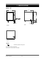
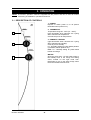
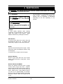
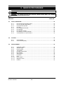
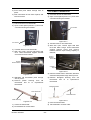
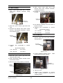
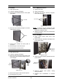
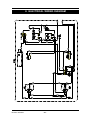
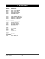
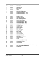
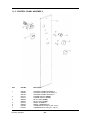
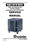
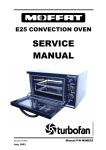
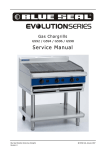
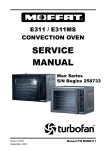
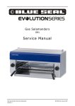
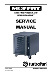
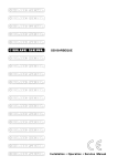
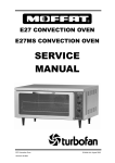
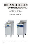
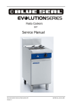
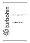
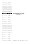
E87 PROOFER
SERVICE
MANUAL
Revision 2/F3520
-1-
WARNING: ALL INSTALLATION AND SERVICE REPAIR WORK MUST BE CARRIED
OUT BY QUALIFIED PERSONS ONLY.
Revision 2/F3520
-2-
CONTENTS
This manual is designed to take a more in depth look at the E87 prover for the purpose of making
the unit more understandable to service people.
There are settings explained in this manual that should never require to be adjusted, but for
completeness and those special cases where these settings are required to change, this manual
gives a full explanation as to how, and what effects will result.
SECTION
PAGE NO.
1.
SPECIFICATIONS .........................................................................................................5
2.
INSTALLATION .............................................................................................................7
3.
OPERATION ...................................................................................................................8
3.1
3.2
4.
Description of Controls
Explanation of Control System
MAINTENANCE .............................................................................................................10
4.1
4.2
Cleaning
Routine Procedures
5.
TROUBLE SHOOTING GUIDE ......................................................................................12
6.
SERVICE PROCEDURES ..............................................................................................14
6.1
6.2
6.3
Fault Diagnosis
Access
Replacement
7.
ELECTRICAL SCHEMATICS ........................................................................................20
8.
ELECTRICAL WIRING DIAGRAMS ..............................................................................21
9.
SPARE PARTS ..............................................................................................................22
10.
ACCESSORIES / OPTIONS ..........................................................................................23
11.
PARTS DIAGRAM .........................................................................................................24
11.1
11.2
12.
Main Assembly
Control Panel Assembly
SERVICE CONTACTS ..................................................................................................27
IMPORTANT: MAKING ALTERATIONS MAY VOID WARRANTIES AND APPROVALS.
Revision 2/F3520
-3-
Revision 2/F3520
-4-
1. SPECIFICATIONS
770
(30.3)
890
710
(28.0)
SIDE
FRONT
PLAN
LEGEND
- Electrical connection entry point
Dimensions shown in millimetres.
Dimensions in inches shown in brackets.
Revision 2/F3520
-5-
130
150
(5.9)
(5.1)
50
(1.95)
(35.0)
MODEL: E87
LOCATION
To ensure correct operation the following
minimum installation clearances are to be
adhered to:
Rear:
Left-hand side:
Right-hand side:
25 mm / 1”
25 mm / 1”
25 mm / 1”
PROVER INTERNAL DIMENSIONS
Width:
Height:
Depth:
Oven Volume:
460 mm / 18”
610 mm / 24”
660 mm / 26”
0.19 m³ / 6.5 ft³
PROVER RACK SIZE
Width:
Depth:
460 mm / 18”
660 mm / 26”
No. of rack positions:
8
Rack position spacing: 75 mm / 3”
ELECTRICAL SUPPLY SPECIFICATION
OPTIONS
100-120 V AC 60 Hz, 12.5 A, 1.5 kW @ 120 V
220-240 V AC 50 Hz, 7.5 A, 1.8 kW @ 240 V
ELECTRICAL
PLUG
REQUIREMENTS
SPECIFICATION
Australia
3-pin 250V 10A, AS/NZ 3112
Canada
3-pin 250V 15A, NEMA 6-15
New Zealand
3-pin 250V 10A, AS/NZ 3112
United Kingdom 3-pin 250V 13A fused, BS
1363A
United States 3-pin 250V 15A, NEMA 6-15
Other Countries 3-pin 250V 10A minimum, type
to meet country standards
Revision 2/F3520
-6-
2. INSTALLATION
WARNING: THIS APPLIANCE MUST BE GROUNDED.
WARNING: ALL INSTALLATION AND SERVICE REPAIR WORK MUST BE CARRIED
OUT BY QUALIFIED PERSONS ONLY.
ASSEMBLY OF CASTORS
It is most important that the prover is installed
correctly and that the operation is correct
before use. Installation shall comply with local
electrical, health and safety requirements.
1. Remove the castors from inside the
prover.
2. Remove side racks and water trough.
3. Lift and place the prover onto its back.
Attach the two swivel castors (with brake)
to the front of the prover with the screws
provided. Attach the two rigid castors to
the rear.
BEFORE CONNECTION TO POWER
SUPPLY
Unpack and check unit for damage and report
any damage to the carrier and dealer. Report
any deficiencies to your dealer.
Fit the
castors which are packed inside the unit.
Check that the available power supply is
correct to that shown on the rating plate
located on the right-hand side panel.
4. Lift the prover onto its castors and refit the
water trough and side racks.
DOUBLE STACKING UNITS
When it is desired to mount a Turbofan
Countertop Convection Oven on an E87
prover, a double stacking kit may be used.
Available from your dealer or Turbofan
distributor (see Spare Parts).
When mounting one prover on top of another,
a double stacking kit is also required.
220-240 V AC 50 Hz, 7.5 A, 1.8 kW @ 240 V
100-120 V AC 60 Hz, 12.5 A, 1.5 kW @ 120 V
LOCATION
To ensure correct operation the following
minimum installation clearances are to be
adhered to:
RATING PLATE LOCATION
Rear
Left-hand side
Right-hand side
25mm / 1”
25mm / 1”
25mm / 1”
The rating plate for the E87 prover is located
at the bottom left corner of the RH side panel.
ELECTRICAL CONNECTION
E87 provers are supplied with pre-fitted cords.
Ensure unit is fitted with correct cord and plug
for the installation (refer to the specifications
section).
Should changing of the cord be necessary,
gain access to the electrical connection
terminal block and strain relief clamp by
removing the control panel.
Rating Plate
Figure 2.2
Figure 2.1
Revision 2/F3520
-7-
3. OPERATION
NOTE: A full user’s operation manual is supplied with the product and can be used for further
referencing of installation, operation and service.
3.1 DESCRIPTION OF CONTROLS
1. POWER
Depress to switch power on or off (switch
illuminates when power is on).
2. THERMOSTAT
Temperature range 25 - 40°C (75 - 105°F).
Light illuminates when elements are cycling
ON to maintain set temperature.
Controls the prover air temperature.
1
3. HUMIDITY CONTROL
(Light illuminates when elements are cycling
ON to maintain set humidity).
Controls prover humidity.
LO - Humidity setting for butter based pastries
(croissants, Danish pastries etc).
MED / HI - Humidity setting for yeast based
breads and dough.
2
WATER
Open the prover door. Fill the water trough to
the halfway level in the trough front filling
snout, located on the right hand side.
Remember to top up the water trough when
the level is below the front snout.
3
Revision 2/F3520
-8-
3.2
immersed in the water tank. Should the water
tank level drop below the heating element the
humidity thermostat will cycle Off due to the
sensing bulb reacting to the radiated heat off
the heating element and will prevent the
humidity water tank heating element burning
out through excessive temperature.
EXPLANATION OF CONTROL
SYSTEM
The E87 Prover has a power On/Off switch on
the control panel and isolates power to the
humidity and heating fan and light circuits
when switched Off. When switched On the
switch will illuminate to indicate that the unit is
On and operational. The air circulation fan is
On continuously on all E87 models when the
power switch is in an On position.
E87 models require the operator to manually
fill the water tank and maintain the water tank
level as the water evaporates through
operation.
With all E87 models butter based products
such as croissants and danish pastries should
have the cabinet proofing temperature set
around 25°C (77°F) as higher proofing
temperatures will cause the butter to melt out
of the product, and for yeast based doughs
and breads the proofing temperature should
be set higher at around 40°C (105°F) in order
to activate the yeast in these products.
The proofing system operates on all models,
controls air temperature and humidity levels
by way of an air heating element controlled by
a mechanical bulb and capillary thermostat
and a water tank heating element controlled
by a mechanical bulb and capillary
thermostat.
The air heating element is positioned in the
bottom of the air circulation ducting inside the
cabinet and is directly controlled by the
user-adjustable thermostat mounted to the
control panel. The thermostat sensing bulb is
mounted inside the cabinet to control the
cabinet air temperature to the control panel
setting. An indicator light on the control panel
above this thermostat will illuminate when the
thermostat has the air heating element
operating and will cycling Off with the
thermostat to indicate when the temperature
reaches set point.
On all models the air circulation fan mounted
at the top of the air delivery ducting ensures
that the temperature and humidity throughout
the cabinet is even by creating a low velocity
air circulation system throughout the prover
cabinet. This system overcomes the natural
occurrence of hot air rising and therefore
higher humidity and temperature in the upper
positions of the cabinet as found with proofing
units without forced air circulation.
The user-adjustable thermostat and humidity
controls are required to allow adjustment of
cabinet temperature and humidity levels for
the variations of temperature and humidity
that different product types require.
The water tank heating element controlled by
the humidity level thermostat mounted to the
control panel is used to heat the water tank
water and maintain water tank temperature
between 50°C (122°F) and 80°C (176°F).
This water tank temperature is controlled by
the humidity level thermostat setting between
the adjustments of low and high humidity.
The evaporation rate of the water in the water
tank dependent on its temperature, provides
humidity into the cabinet and accordingly the
setting of the humidity thermostat controls the
rate of evaporation and therefore the humidity
level in the cabinet.
Two cabinet illumination lights are provided in
the E87 models and these 15 watt each
incandescent filament lamps are On
whenever the control panel power switch is
switched on.
To prevent the formation of condensation on
the aluminium frame around the front of the
cabinet and to assist in minimising the
condensation occurring on the door frame and
door glass inner face a resistance wire
heating element is fitted into the cabinet
aluminium extrusion frame. This heating wire
is on whenever the power switch is switched
on and will heat the aluminium frame to a
warm-to-touch temperature.
An indicator light on the control panel above
the humidity dial illuminates when the water
tank element is On, and cycles Off when the
thermostat switches the heating element Off
to provide an indication of the humidity
control. The sensing bulb of the humidity
thermostat is mounted directly on the water
tank heating element which are both
Revision 2/F3520
-9-
4. MAINTENANCE
WARNING: ALL INSTALLATION AND SERVICE REPAIR WORK MUST BE CARRIED
OUT BY QUALIFIED PERSONS ONLY.
This procedure is recommended to be done
once a week. Frequency of cleaning the
element may be increased or decreased
depending on the lime depositing on the
element.
4.1 CLEANING
WARNING: ALWAYS TURN THE
POWER SUPPLY OFF BEFORE
CLEANING.
IMPORTANT: THIS UNIT IS NOT
WATER PROOF.
DO NOT USE A WATER JET SPRAY TO
CLEAN INTERIOR OR EXTERIOR OF
THIS UNIT.
CABINET
A good quality stainless steel cleaning
compound is recommended for cleaning the
inside and outside of the cabinet. Harsh
abrasive cleaners may damage the surface.
SIDE RACKS
To remove, take hold of the centre rung and
lift towards the prover top. To replace, hold
horizontally, engage in holes and push down.
DOOR
Open the door and lift up off its hinges. Wash
with warm water and detergent solution using
a soft sponge.
To refit the door, simply fit onto its hinges.
WATER TROUGH
Remove right hand side rack and remove
trough. Clean with warm, soapy water. Rinse
thoroughly.
WATER TROUGH ELEMENT
When the element becomes limed / scaled,
remove water trough and clean. Replace
water trough and half fill with white vinegar or
acetic acid then fill to the normal level with
water. Switch unit on. Set humidity control to
‘Hi’ and run for approximately 30 minutes.
Remove trough and clean element with damp
cloth when cooled. Wash out trough and refit
to unit.
Revision 2/F3520
-10-
4.2 ROUTINE PROCEDURES
PROCEDURE
INTERVAL
DOOR HINGES
Check for wear.
12 months
DOOR CATCH
Ensure that catch is adjusted such that the door
closes properly.
12 months
ELEMENTS
Check that element resistances are correct to their
ratings. (refer 6.3.6, 6.3.7).
12 months
WET ELEMENT
Remove scaling (refer section 4.1).
HOTWIRE
Check that hotwire is working.
Revision 2/F3520
-11-
As required
12 months
5. TROUBLE SHOOTING
WARNING: ALL INSTALLATION AND SERVICE REPAIR WORK MUST BE CARRIED
OUT BY QUALIFIED PERSONS ONLY.
FAULT
THE PROVER DOES NOT
OPERATE / START
POSSIBLE CAUSE
The prover is not plugged into
the wall socket.
REMEDY
Plug in.
The mains isolating switch on
Turn on.
the wall, circuit breaker or fuses
are “off” at the power board.
The power switch on the prover Depress switch. Switch will
is off.
illuminate.
Incorrect electrical supply.
(Refer fault diagnosis 6.1.1)
Ensure electrical supply correct.
Power switch on unit faulty.
(Refer fault diagnosis 6.1.1)
Replace.
(Refer service section 6.3.3)
Blown bulb.
Replace.
(Refer service section 6.3.1)
No power to light.
(Refer fault diagnosis 6.1.2)
Correct fault.
FAN DOES NOT OPERATE
Faulty fan.
(Refer fault diagnosis 6.1.3)
Replace.
(Refer service section 6.3.8)
NO HEAT
Thermostat faulty.
(Refer fault diagnosis 6.1.4)
Replace.
(Refer service section 6.3.4)
Element blown.
(Refer fault diagnosis 6.1.4)
Replace.
(Refer service section 6.3.6)
NO TEMPERATURE
CONTROL
Faulty thermostat.
(Refer fault diagnosis 6.1.5)
Replace.
Refer service section 6.3.4)
NO HUMIDITY
No water in trough.
Fill trough with water.
Faulty thermostat.
(Refer fault diagnosis 6.1.6)
Replace.
(Refer service section 6.3.5)
Element blown.
(Refer fault diagnosis 6.1.6)
Replace.
(Refer service section 6.3.7)
NO HUMIDITY CONTROL
Faulty thermostat.
(Refer fault diagnosis 6.1.7)
Replace.
(Refer service section 6.3.5)
SLOW RECOVERY
Overloading of prover.
Reduce batch size.
Door opened unnecessarily.
Do not open unnecessarily.
Electrical supply incorrect.
Check supply voltage is as per
rating plate voltage.
Fan faulty.
(Refer fault diagnosis 6.1.3)
Replace.
(Refer service section 6.3.8)
OVEN LIGHT NOT
ILLUMINATING
Revision 2/F3520
-12-
FAULT
POSSIBLE CAUSE
REMEDY
NO HEATING / HUMIDITY
INDICATOR
Indicator faulty.
(Refer fault diagnosis 6.1.8)
Replace.
(Refer service section 6.3.2)
CONDENSATION ON TOP OF
FRAME
Hot wire faulty.
(Refer fault diagnosis 6.1.9)
Replace.
(Refer service section 6.3.12)
DOOR DOES NOT CLOSE
Tray in way of door.
Correctly position tray in rack.
Damaged door magnet.
Replace.
(Refer service section 6.3.11)
Revision 2/F3520
-13-
6. SERVICE PROCEDURES
WARNING: ENSURE POWER SUPPLY IS SWITCHED OFF BEFORE SERVICING.
WARNING: ALL INSTALLATION AND SERVICE REPAIR WORK MUST BE CARRIED
OUT BY QUALIFIED PERSONS ONLY.
SECTION
6.1
FAULT DIAGNOSIS.............................................................................................................. 15
6.1.1
6.1.2
6.1.3
6.1.4
6.1.5
6.1.6
6.1.7
6.1.8
6.1.9
6.2
Prover Does Not Operate / Start ......................................................................... 15
Prover Lights Not Illuminating ............................................................................. 15
Fan Does Not Operate ........................................................................................ 15
No Heat ............................................................................................................... 15
No Temperature Control ...................................................................................... 15
No Humidity ......................................................................................................... 15
No Humidity Control ............................................................................................ 15
No Heating / Humidity Indicator ........................................................................... 15
Condensation On Top Of Frame ......................................................................... 15
ACCESS ................................................................................................................................ 16
6.2.1
6.2.2
6.3
PAGE NO.
Control Panel ....................................................................................................... 16
Control Panel (Rear)............................................................................................ 16
REPLACEMENT ................................................................................................................... 16
6.3.1
6.3.2
6.3.3
6.3.4
6.3.5
6.3.6
6.3.7
6.3.8
6.3.9
6.3.10
6.3.11
6.3.12
Revision 2/F3520
Light Bulb / Glass ................................................................................................ 16
Indicator Light ...................................................................................................... 16
Power Switch ....................................................................................................... 16
Thermostat........................................................................................................... 17
Humidity Thermostat ........................................................................................... 17
Dry Element ......................................................................................................... 18
Wet Element ........................................................................................................ 18
Fan Motor ............................................................................................................ 18
Door ..................................................................................................................... 19
Door Hinges ......................................................................................................... 19
Magnetic Catch .................................................................................................... 19
Hotwire................................................................................................................. 19
-14-
6.1 FAULT DIAGNOSIS
Element blown
6.1.1 PPOVER DOES NOT OPERATE
With thermostat on and heating check voltage
across dry element terminals. If there is no
voltage check wiring. If voltage is correct,
element is faulty - replace.
Incorrect electrical supply
Check that the voltage across phase and
neutral (L1 and L2) terminals of terminal block
is the voltage as stated on the unit’s electrical
rating plate.
6.1.5 NO TEMPERATURE CONTROL
Thermostat faulty
With thermostat in off position (fully counterclockwise), the heating indicator should be off.
If not, then the thermostat is faulty - replace.
If incorrect, check electrical connection of
supply wiring and / or check electrical supply.
Power switch faulty
Check if power switch latches. If the switch
does not latch, then switch is faulty—replace.
6.1.6 NO HUMIDITY
With switch latched, check voltage across
terminal 1 to terminal 3. If there is no voltage,
check for fault in wiring.
Thermostat faulty
With cold prover, set humidity to ‘HI’. Check
power to terminal 1 of bottom thermostat. If
there is no power then check wiring.
Check voltage across terminal 2 to terminal 3.
If there is no voltage, then switch is faulty—
replace.
Check power at terminal 2.
If there is no
power then the thermostat is faulty - replace.
NOTE: When power switch is latched, it
should illuminate if operating correctly.
Element blown
With humidity thermostat on and heating
check voltage across wet element terminals.
If there is no voltage check wiring. If voltage
is correct, element is faulty - replace.
6.1.2 PROVER LIGHTS NOT ILLUMINATING
No power to light
6.1.7 NO HUMIDITY CONTROL
Check voltage across light bulb terminals. If
there is no voltage then check wiring. If there
is voltage then the lamp is faulty - replace.
Humidity thermostat faulty
Switch the prover on and set the humidity to
‘LO’. Check that the humidity thermostat
cycles on/off, and using a suitable probe
measure the temperature of the water in the
trough. The water temperature should be 50°
C/120°F ± 10%. If the temperature continues
to rise above this then the humidity thermostat
is faulty - replace.
6.1.3 FAN DOESN’T OPERATE
Fan motor faulty
Check the supply voltage across the motor
terminals. If there is no voltage then check
the electrical connections of supply wiring.
If voltage is correct then check the oven fan
for free rotation. Remove any obstruction.
6.1.8 NO HEATING / HUMIDITY
INDICATOR
If fan is free to spin and the voltage supply is
correct, then the motor is faulty—replace.
Indicator faulty
6.1.4 NO HEAT
Check voltage across indicator terminals with
controls on and appropriate thermostat turned
on fully. If the voltage is correct, and the
indicator is not illuminating then the indicator
is faulty - replace. If there is no voltage then
check wiring.
Thermostat faulty
With cold prover, set thermostat to 40°C /
105°F. Check power to terminal 1 of top
thermostat. If there is no power then check
wiring.
6.1.9 CONDENSATION ON TOP OF FRAME
Check power at terminal 2.
If there is no
power then the thermostat is faulty - replace.
Hotwire faulty
Check voltage across hotwire. If there is no
voltage then the hotwire is faulty - replace.
Revision 2/F3520
-15-
6.2 ACCESS
6.3 REPLACEMENT
6.2.1 CONTROL PANEL
6.3.1 LIGHT BULB / GLASS
1) Undo the one screw on top of control
panel.
1) Open the prover door.
2) Pull off lamp cover.
Lamp Covers
One Screw
Figure 6.2.1
Figure 6.3.1
2) Panel is now free to hinge at bottom.
When closing the panel ensure wires and
capillary tube are clear of metal or other
terminals.
3) Unscrew bulb out of fitting.
4) Screw in replacement bulb.
5) Refit lamp cover.
6.2.2 CONTROL PANEL—REAR
6.3.2 INDICATOR LIGHT
1) With control panel open (refer 6.2.1)
remove the wires from the back of the
neon.
Power Switch
Neon Wires
Dry Heating Indicator
Dry Thermostat
Figure 6.3.2
2) From back push neon through front of
panel rotating clockwise.
Wet Heating Indicator
3) Push new neon in from front of panel, and
reconnect wires.
6.3.3 POWER SWITCH
Wet Thermostat
1) With control panel open (refer 6.2.1)
remove the wires from the back of the
switch, noting their positions.
Power Switch
Wires
Figure 6.2.2
Revision 2/F3520
Figure 6.3.3
-16-
2) From back push switch through front of
panel.
6.3.5 HUMIDITY THERMOSTAT
3) Push new switch in from front of panel, and
reconnect wires.
1) Pull knob off front of thermostat
2) Open control panel (refer 6.2.1.) and undo
2 screws securing thermostat.
6.3.4 THERMOSTAT
1) Pull knob off front of thermostat
2) Open control panel (refer 6.2.1) and undo
2 screws securing thermostat.
Two Screws
Figure 6.3.7
Two Screws
3) Transfer wires to new thermostat.
Figure 6.3.4
4) With door open, remove right hand side
rack and water trough. Undo thermostat
support bracket screw and remove
bracket. Remove clips holding capillary to
element.
3) Transfer wires to new thermostat.
4) With door open, remove right hand side
rack. Undo thermostat support bracket
screw and remove bracket.
Support
Bracket
Screw
Support
Bracket Screw
Capillary
Clips
Figure 6.3.8
Figure 6.3.5
5) Remove rubber bush in side wall, withdraw
old thermostat phial through side of prover.
5) Withdraw old thermostat phial through
side of prover.
6) Remove fibreglass sleeving from old
thermostat and fit to replacement
thermostat
6) Remove plastic
thermostat and
thermostat.
sleeving from old
fit to replacement
Fibreglass Sleeve
Thermostat Phial
Thermostat Phial
Plastic Sleeving
Figure 6.3.9
Figure 6.3.6
7) Insert new thermostat.
7) Insert new thermostat.
8) Re-assemble in reverse order.
8) Re-assemble in reverse order.
Revision 2/F3520
-17-
4) Open control panel (refer 6.2.1) and
remove wires from element terminals,
noting their positions.
6.3.6 DRY ELEMENT
1) Open control panel (refer 6.2.1), remove
wires from element terminals noting
position.
5) Unscrew the element from inside control
housing.
Element
Screws
Element
Terminals
Figure 6.3.13
Figure 6.3.10
6) Pull element carefully from the inside of
prover to remove .
2) With door open, remove right hand side
rack
7) Replace and re-assemble in reverse
order.
Wet Element Ratings
3) Unscrew the element from inside control
housing. Pull element carefully to remove
from inside of prover.
110 - 120 Volt
20.1 ohms
220 - 240 Volt
71.5 ohms
6.3.8 FAN MOTOR
Element
Screws
1) Open control panel (refer 6.2.1), and
remove wires from fan motor terminals,
noting positions.
Figure 6.3.11
Fan Motor
Terminals
4) Replace and re-assemble in reverse
order.
Dry Element Ratings
110 - 120 Volt
20.5 ohms
220 - 240 Volt
70.5 ohms.
Figure 6.3.14
2) Loosen retaining bracket screw.
bracket down to bottom position.
6.3.7 WET ELEMENT
Slide
1) With door open, remove right hand side
rack and water trough.
2) Undo thermostat support bracket screw
and remove bracket.
3) Remove clips holding capillary to element.
Retaining
Bracket Screw
Support
Bracket
Screw
Figure 6.3.15
3) Slide out motor.
Capillary
Clips
4) Replace and re-assemble in reverse
order, ensuring bracket is secured in
highest position.
Figure 6.3.12
Revision 2/F3520
-18-
6.3.9 DOOR
6.3.11 MAGNETIC CATCH
1) Open prover door.
1) Open prover door.
2) Lift door vertically off hinges.
2) Open control panel.
3) Remove door handle and door catch plate
(two bolts).
3) Unscrew two screws securing magnetic
door catch to prover.
Two Screws
Two Bolts
Figure 6.3.16
Figure 6.3.19
4) Drill out rivets securing hinges to old door
frame (two per hinge).
NOTE: A spanner may be required to hold
the nuts located inside the control panel,
behind the magnetic catch.
4) Replace magnetic catch and re-assemble
in reverse order.
6.3.12 HOTWIRE
Rivets
1) Open control panel (refer 6.2.1) and
prover door.
2) Remove silicone extrusion seal strips from
prover door frame.
Figure 6.3.17
5) Secure door handle and catch plate to
new door.
6) Rivet hinges to new door frame.
7) Re-hang door on E87 prover.
Silicone
Extrusion
Strips (3)
6.3.10 DOOR HINGES
1) Open prover door.
2) Lift door vertically off hinges.
Figure 6.3.20
3) Drill out rivets securing hinges to door and
E87 prover (two rivets per hinge), and remove hinges.
3) Remove hotwire retaining sleeves (9) from
prover frame.
Retaining
Sleeves (9)
Door
Hinges
Hinge
Rivets
Figure 6.3.21
Figure 6.3.18
4) Remove hotwire
wiring positions.
4) Rivet new hinges to door and E87 prover.
prover,
noting
5) Replace and re-assemble in reverse
order.
5) Re-hang door on prover.
Revision 2/F3520
from
-19-
7. ELECTRICAL CIRCUIT SCHEMATIC
Revision 2/F3520
-20-
8. ELECTRICAL WIRING DIAGRAM
Revision 2/F3520
-21-
9. SPARE PARTS
PART NO
DESCRIPTION
CONTROLS
021473
021514
014233
015485
020823
020849
014218
014219
015539
015538
Switch - Power (220-240V)
Switch - Power (110V)
Thermostat (Temperature)
Thermostat (Humidity)
Knob - Thermostats
Neon Indicator
Oven Lamp Bulb - 15W (220-240V)
Oven Lamp Bulb - 15W (110V)
Heating Wire - 100W (220-240V)
Heating Wire - 100W (110V)
MOTOR & ELEMENTS
013998
Motor and Fan (220-240V)
013999
Motor and Fan (110V)
014001
Dry Element (220-240V)
015759
Dry Element (110V)
015224
Wet Element (220-240V)
015230
Wet Element (110V)
DOOR
021461
021468
017575
018947
Door Assembly
Handle
Hinge
Magnetic catch
RACKS
015477
Side Rack
STACKING KIT
21547
Double Stacking Kit
Revision 2/F3520
-22-
10. ACCESSORIES
DOUBLE STACKING KIT (PART NO
021547) - For use with E32 / G32 convection ovens
6” LEG OPTION (PART NO 15274)
DRIP TROUGH (PART NO 15295)
STANDOFF KIT (PART NO 21336) Enables prover to take 16” wide trays
Revision 2/F3520
-23-
11. PARTS DIAGRAMS
11.1 MAIN ASSEMBLY
Revision 2/F3520
-24-
Pos
Part No.
Description
1
2
3
4
5
6
7
8
015236
015253
---------015483
018738
015244
015278
013998
013999
015243
015242
015241
018947
015249
021342
014218
014219
015248
014001
015759
015224
015230
012272
012271
014725
015474
002138
002441
018737
015237
015235
015234
017858
013885
013890
015240
013586
015477
015481
016650
015539
015538
015238
015239
021464
021461
021468
---------015295
017575
WRAPPER
SUPPORT DISC
INSULATION
LINER
LINER SUPPORT
RACK MOUNTING PLATE
FAN LOCATING BRACKET
FAN/MOTOR ASSEMBLY - 240V
FAN/MOTOR ASSEMBLY - 110V
FAN CLAMP BRACKET
FAN COVER
DUCTING
MAGNETIC CATCH
CAPILLARY BRACKET
LAMP HOLDER ASSEMBLY
BULB (15w, 240V)
BULB (15w, 110V)
DUCTING HEAT SHIELD
DRY ELEMENT (600w, 240V)
DRY ELEMENT (600w, 110V)
WET ELEMENT (800w, 240V)
WET ELEMENT (800w, 110V)
CLAMP TOP
CLAMP BOTTOM
HANGER STUD
WATER TROUGH
CABLE CLAMP
INSULATOR
BASE STIFFENER
SPACER TUBE
BACK PANEL
BASE PANEL
CABLE CLAMP
CASTOR - 5" RIGID
CASTOR - 5" SWIVEL
CONTROL HOUSING
MAINS TERMINAL BLOCK
SIDE RACK
HANGER SPACER
FRAME
HEATING WIRE (100w, 240V)
HEATING WIRE (100w, 110V)
STRIP INSERT - SHORT
STRIP INSERT - LONG
CATCH PLATE
DOOR ASSEMBLY
DOOR HANDLE
CONTROL PANEL ASSEMBLY (REFER TO SECTION 11.2)
DRIP TROUGH (OPTIONAL EXTRA)
DOOR HINGE
9
10
11
12
13
14
15
16
17
18
19
20
21
22
23
24
25
26
27
28
29
30
31
32
33
34
35
36
37
38
39
40
41
42
43
44
Revision 2/F3520
-25-
11.2 CONTROL PANEL ASSEMBLY
Pos
Part No.
Description
1
004726
004805
004724
021473
021514
020849
023857
021472
020823
015485
014233
CONTROL PANEL BAKBAR ºC
CONTROL PANEL BLUE SEAL °C
CONTROL PANEL MOFFAT ºF
POWER SWITCH (240V)
POWER SWITCH (110V)
PILOT LIGHT (240V)
PILOT LIGHT (110V)
KNOB - HUMIDITY
KNOB - THERMOSTAT
THERMOSTAT 50-80ºC (120-175°F)
THERMOSTAT 0-40ºC (32 - 105°F)
2
3
4
5
6
7
Revision 2/F3520
-26-
11. SERVICE CONTACTS
AUSTRALIA
VICTORIA - MOFFAT PTY
HEAD OFFICE AND MAIN WAREHOUSE
740 Springvale Road
Mulgrave VIC 3170
Spare Parts Department
NEW SOUTH WALES - MOFFAT PTY
Unit 8/142 James Ruse Drive
Rosehill NSW 2142
Spare Parts
Tel (03) 9518 3888
Fax (03) 9518 3838
Free Call 1800 337 963
Fax (03) 9518 3895
Free Call 1800 337 963
Fax (03) 9518 3895
QUEENSLAND - MOFFAT PTY
30 Prosperity Place
Geebung QLD 4034
Spare Parts
Free Call 1800 337 963
Fax (03) 9518 3895
SOUTH AUSTRALIA - MOFFAT PTY
Suite 8/71 Fullarton Rd
Kent Town SA 5067
Spare Parts
Tel (08) 8431 0522
Free Call 1800 337 963
WESTERN AUSTRALIA - MOFFAT PTY
PO Box 689
Joondalup Business Centre WA 6027
Spare Parts
Tel (08) 9305 8855
Free Call 1800 337 963
NATIONAL COVERAGE FOR 24 HOUR SERVICE OR MAINTENANCE DIAL
FREE CALL 1800 622 216 (AUSTRALIA ONLY)
CANADA
Lessard Agencies Limited
PO Box 97
Stn “D”
Toronto, ONT M6P 3J5
Tel (416) 766 2764
Fax (416) 760 0394
Free Call 1 888 537 7273
NEW ZEALAND
CHRISTCHURCH - MOFFAT LTD
16 Osborne St
PO Box 10-001
Christchurch
Spare Parts
Free Call 0800 Moffat
(0800 663 328)
Tel (03) 389 1007
Fax (03) 389 1276
AUCKLAND - MOFFAT LTD
4 Waipuna Road
Mt Wellington
Auckland
Spare Parts
Revision 2/F3520
Tel (09) 574 3150
Fax (09) 574 3159
Free Call 0800 Moffat
(0800 663 328)
-27-
UNITED KINGDOM
BLUESEAL LTD
Units 6-7 Mount St
Business Park
Birmingham B7 5QU
England
Tel 0121-327 5575
Fax 0121-327 9711
UNITED STATES OF AMERICA
MOFFAT INC.
3765 Champion Blvd
Winston-Salem
NC27115
Tel 1-800-551 8795
Fax 336 661 9546
NATIONAL COVERAGE FOR SERVICE OR MAINTENANCE DIAL
FREE CALL 1800 551 8795 (USA ONLY)
Revision 2/F3520
-28-