1
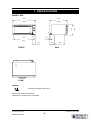
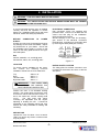
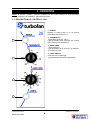
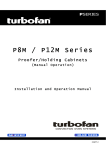
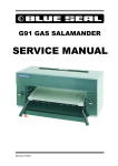
Manuals and Documents
Brought to you by
Wechillit.com Ltd
WCI Group House
18 Pride Hill
Shrewsbury SY1 1DQ
Tel: 01743 289418
Fax: 01743 289416
Web: www.wechillit.com
E26 CONVECTION OVEN
SERVICE
MANUAL
E26 Convection Oven
Revision 6/F3503
-1-
© Moffat Ltd, April 2005
WARNING: ALL INSTALLATION AND SERVICE REPAIR WORK MUST BE CARRIED
OUT BY QUALIFIED PERSONS ONLY.
E26 Convection Oven
Revision 6/F3503
-2-
© Moffat Ltd, April 2005
CONTENTS
This manual is designed to take a more in depth look at the E26 convection oven for the purpose of
making the unit more understandable to service people.
There are settings explained in this manual that should never require to be adjusted, but for
completeness and those special cases where these settings are required to change, this manual
gives a full explanation as to how, and what effects will result.
SECTION
PAGE NO.
1.
SPECIFICATIONS......................................................................................................... 5
2.
INSTALLATION ............................................................................................................ 7
3.
OPERATION .................................................................................................................. 8
3.1
3.2
4.
Description of Controls
Explanation of Control System
MAINTENANCE............................................................................................................. 10
4.1
4.2
Cleaning
Routine Procedures
5.
TROUBLE SHOOTING GUIDE ..................................................................................... 11
6.
SERVICE PROCEDURES ............................................................................................. 13
6.1
6.2
6.3
6.4
Fault Diagnosis
Access
Replacement
Adjustment / Calibration
7.
ELECTRICAL SCHEMATIC .......................................................................................... 23
8.
ELECTRICAL WIRING DIAGRAM................................................................................ 24
9.
SPARE PARTS.............................................................................................................. 26
10.
ACCESSORIES / OPTIONS.......................................................................................... 27
IMPORTANT: MAKING ALTERATIONS MAY VOID WARRANTIES AND APPROVALS.
E26 Convection Oven
Revision 6/F3503
-3-
© Moffat Ltd, April 2005
11.
PARTS DIAGRAM ........................................................................................................ 28
11.1
11.2
12.
Main Assembly
Control Panel Assembly
SERVICE CONTACTS.................................................................................................. 31
APPENDIX A. DOUBLE STACKING KIT .............................................................................. 33
E26 Convection Oven
Revision 6/F3503
-4-
© Moffat Ltd, April 2005
1. SPECIFICATIONS
668
668
(34.9)
(26.3)
430
430
885
885
1
E
1
791
791
45
45
(31.1)
(1.75)
(16.9)
MODEL: E26
E
124
120
179
179
395
395
(4.9)
(7.0)
(15.5)
FRONT
SIDE
1
E
PLAN
LEGEND
- Electrical connection entry point
Dimensions shown in millimetres.
Dimensions in inches shown in brackets.
E26 Convection Oven
Revision 6/F3503
-5-
© Moffat Ltd, April 2005
LOCATION
To ensure correct ventilation for the motor and
controls the following minimum installation
clearances are to be adhered to:
Top
Rear
Left-hand side
Right-hand side
200mm / 8”
25mm / 1”
25mm / 1”
25mm / 1”
OVEN INTERNAL DIMENSIONS
Width
Height
Depth
Oven Volume
635 mm / 25”
270 mm / 10.5”
500 mm / 19.5”
0.14 m³ / 5.0ft³
OVEN RACK SIZE
Width
Depth:
600 mm
400 mm
ELECTRICAL SUPPLY SPECIFICATION
OPTIONS
220Vac, 50/60Hz, 11A, 2.4kW @ 220V
230-240Vac, 50Hz, 10A, 2.4kW @ 240V
ELECTRICAL PLUG SPECIFICATION
REQUIREMENTS
Australia
3-pin 250V 10A, AS/NZ 3112
New Zealand
3-pin 250V 10A, AS/NZ 3112
United Kingdom 3-pin 250V 13A fused, BS
1363A
Other Countries 3-pin 250V 10A minimum, type
to meet country standards
E26 Convection Oven
Revision 6/F3503
-6-
© Moffat Ltd, April 2005
2. INSTALLATION
WARNING: THIS APPLIANCE MUST BE GROUNDED.
WARNING: ALL INSTALLATION AND SERVICE REPAIR WORK MUST BE CARRIED
OUT BY QUALIFIED PERSONS ONLY.
ELECTRICAL CONNECTION
It is most important that the oven is installed
correctly and that the operation is correct
before use. Installation shall comply with local
electrical, health and safety requirements.
E26 convection ovens are supplied with
pre-fitted cords. Ensure unit is fitted with the
correct cord and plug for the installation.
Refer specifications section.
Should changing of the cord be necessary,
gain access to the electrical connection
terminal block, grounding lug, and strain relief
by removing the back panel (four screws).
BEFORE CONNECTION TO POWER
SUPPLY
Unpack and check unit for damage and report
any damage to the carrier and dealer. Report
any deficiencies to your dealer. Check that
the available power supply is correct to that
shown on the rating plate located on the righthand side panel.
L1
Phase
RED
BROWN
BLACK
E26
220Vac, 50/60Hz, 11A, 2.4kW @ 220V
230-240Vac, 50Hz, 10A, 2.4kW @ 240V
L2
Ground
Neutral
BLACK
BLUE
WHITE
GREEN
GREEN/YELLOW
WARNING: THIS APPLIANCE MUST
BE GROUNDED / EARTHED
Figure 2.1
LOCATION
RATING PLATE LOCATION
To ensure correct ventilation for the motor,
and controls the following minimum
installation clearances are to be adhered to:
The rating plate for the E26 convection oven
is located at the bottom left corner of the RH
side panel.
Top
Rear
Left-hand side
Right-hand side
200mm / 8”
25mm / 1”
25mm / 1”
25mm / 1”
IMPORTANT:
THE OVEN VENT
LOCATED ON THE CABINET TOP
MUST NEVER BE OBSTRUCTED.
Position the oven in its allocated working
position. Use a spirit level to ensure the oven
is level from side to side and front to back. (If
this is not carried out, uneven cooking could
occur).
The feet used with bench
mounting are adjustable and will require
adjusting in levelling the unit. It should be
positioned so the operating panel and oven
shelves are easily reachable for loading and
unloading.
Rating Plate
Figure 2.2
BEFORE USE
Operate the oven for about 1 hour at 200°C
(400°F) to remove any fumes or odours which
may be present.
E26 Convection Oven
Revision 6/F3503
-7-
© Moffat Ltd, April 2005
3. OPERATION
NOTE: A full user’s operation manual is supplied with the product and can be used for further
referencing of installation, operation and service.
3.1 DESCRIPTION OF CONTROLS - E26
1. POWER
Depress to switch power on or off (switch
illuminates when power is on).
2. THERMOSTAT
Temperature range 50 - 250°C.
Light illuminates when elements are cycling
ON to maintain set temperature.
1
3. BAKE TIMER
1 Hour bake timer.
(Light illuminates when “time up” (0) reached,
and buzzer sounds).
4. LIGHT SWITCH
Push switch to activate light.
(Light illuminates while button depressed).
2
3
4
E26 Convection Oven
Revision 6/F3503
-8-
© Moffat Ltd, April 2005
3.2
‘Off’ position, the element relies on the
thermostatic control to prevent it switching on.
Accordingly, if the oven temperature drops
below approximately 20°C the thermostat and
element may cycle on at this setting.
EXPLANATION OF CONTROL
SYSTEM
The E26 Turbofan convection ovens feature
multi-function operator controls for which a
correct understanding of their operation is
required before carrying out any service or
fault repair work. The control device functions
are explained as follows:
The following Troubleshooting Guide should
be used to identify any incorrect oven
operation. On correct identification of the
operating fault the Troubleshooting Guide will
make reference to the corrective action
required, or refer to the Fault Diagnosis
section and/or Service section to assist in
correction of the fault.
A power switch on the control panel isolates
power to all the controls of the oven. With the
power switch Off all functions of the oven are
inoperable.
With the power switch On (illuminated) power
is directly supplied to the 60 minute bake
timer, door microswitch, temperature control
circuit, fan motor, and the light switch. The
light switch will turn the oven light on when the
door is closed, but only whilst the light switch
is held in.
The door microswitch on the E26 oven
controls the oven light only. Accordingly the
light will come on when the door is opened but
the circulation fan and fan element will remain
on.
The 60 minute timer is a mechanical timer and
can therefore be operated with the oven’s
power switch On or Off. However, only with
the oven’s power switch On will the switch
contacts of the 60 minute timer turn on the
time-up buzzer and illuminate the time-up
indicator on the control panel. The buzzer
and time-up indicator provide indication that
the time setting has run down to zero and at
this point will remain On continuously until the
60 minute timer has been manually set back
to the Off (vertical) position. The 60 minute
timer does not control any other part of the
oven’s operating system as this timer is
independent of the temperature control and
heating system.
The temperature control of these ovens is with
a capillary type thermostat which can be set to
a required cooking temperature.
The E26 has an element coiled around the
circulation fan in the rear of the oven. Power
to the element is provided directly from the
thermostat. The control panel indicator light
above the thermostat knob cycles on and off
with the thermostat to indicate when the
element is on and the oven is heating. In the
E26 Convection Oven
Revision 6/F3503
-9-
© Moffat Ltd, April 2005
4. MAINTENANCE
WARNING: ALL INSTALLATION AND SERVICE REPAIR WORK MUST BE CARRIED
OUT BY QUALIFIED PERSONS ONLY.
4.1 CLEANING
OVEN SEALS
To remove, hold at their centre point and pull
forward until they unclip. Remove side seals
first, then top and bottom. The seals may be
washed in the sink, but take care not to cut or
damage them. To replace, ensure that the lip
is facing the oven opening. Fit the top and
bottom seals first, then the side seals.
WARNING: ALWAYS TURN THE
POWER SUPPLY OFF BEFORE
CLEANING.
IMPORTANT: THIS UNIT IS NOT
WATER PROOF.
DO NOT USE A WATER JET SPRAY TO
CLEAN INTERIOR OR EXTERIOR OF
THIS UNIT.
OVEN DOOR GLASS
Clean with conventional glass cleaners
EXTERIOR
4.2 ROUTINE PROCEDURES
Clean with a good quality stainless steel
cleaning compound. Harsh abrasive cleaners
may damage the surface.
DOOR SEALS
Check for deterioration
INTERIOR
12 months
ELEMENTS
Ensure that the oven chamber is cool. Do not
use wire brushes, steel wool or other abrasive
materials. Clean the oven regularly with a
good quality oven cleaner. Take care not to
damage the fan or the tube at the right side of
the oven which controls the thermostat.
Check that element resistances
12 months
are correct to their ratings (refer
6.3.9)
OVEN RACKS
To remove, slide out to the stop position, raise
the front edge up, and lift out.
BOTTOM BAFFLE
Slide forward and lift out. When replacing,
ensure tray is pushed fully in to rear of oven.
SIDE RACKS
Loosen rear thumbscrew 2-3 turns. Remove
front thumbscrew and pull rack forward to disengage rear screw then lift out. Replace in
reverse order.
FAN BAFFLE
To remove, undo thumbscrew (counterclockwise rotation) at top of baffle and
remove. Lift baffle out from rear of oven by
tilting forward while lifting out of location studs
at baffle base. Replace in reverse order.
E26 Convection Oven
Revision 6/F3503
-10-
© Moffat Ltd, April 2005
5. TROUBLE SHOOTING
WARNING: ALL INSTALLATION AND SERVICE REPAIR WORK MUST BE CARRIED
OUT BY QUALIFIED PERSONS ONLY.
FAULT
THE OVEN DOES NOT
OPERATE / START
POSSIBLE CAUSE
REMEDY
The mains isolating switch on
Turn on.
the wall, circuit breaker or fuses
are “off” at the power board.
The power switch on the oven is Depress switch. Switch will
illuminate.
off.
FAN DOESN’T OPERATE
Incorrect electrical supply.
(Refer fault diagnosis 6.1.1)
Ensure electrical supply correct.
Power switch on unit faulty.
(Refer fault diagnosis 6.1.1)
Replace.
(Refer service section 6.3.4)
Fan motor faulty.
(Refer fault diagnosis 6.1.2)
Replace.
(Refer service section 6.3.10)
Wiring.
Check and tighten any loose
wiring.
OVEN LIGHT NOT
Blown bulb.
ILLUMINATING - DOOR OPEN
Replace.
(Refer service section 6.3.1)
No power to light.
(Refer fault diagnosis 6.1.3)
Correct fault.
Blown bulb.
Replace.
(Refer service section 6.3.1)
Light switch faulty.
(Refer fault diagnosis 6.1.4)
Replace.
(Refer service section 6.3.4)
60 MINUTE TIMER WILL NOT
TIME DOWN
Timer faulty.
Replace.
(Refer service section 6.3.6)
60 MINUTE TIMER
INACCURATE BELOW 20
MINUTES
Timer not set correctly.
For timer settings below 20
minutes, always rotate past 20
minutes, then back to desired
time.
Zero (time up) position not set
correctly.
(Refer service section 6.4.3)
Buzzer faulty.
(Refer fault diagnosis 6.1.5)
Replace.
(Refer service section 6.3.5)
Timer not switching on buzzer.
(Refer fault diagnosis 6.1.5)
Replace.
(Refer service section 6.3.6)
Indicator faulty.
(Refer fault diagnosis 6.1.6)
Replace.
(Refer service section 6.3.3)
OVEN LIGHT NOT
ILLUMINATING - DOOR
CLOSED
60 MINUTE TIMER NO TIME
UP BUZZER
60 MINUTE TIMER NO TIME
UP INDICATOR
E26 Convection Oven
Revision 6/F3503
-11-
© Moffat Ltd, April 2005
FAULT
NO HEAT
POSSIBLE CAUSE
REMEDY
No power to thermostat.
(Refer fault diagnosis 6.1.7)
Identify fault and correct.
Thermostat faulty.
(Refer fault diagnosis 6.1.7)
Replace.
(Refer service section 6.3.7)
Fan element faulty
(Refer fault diagnosis 6.1.10)
Correct element fault.
(Refer Fault: Fan Element)
NO TEMPERATURE
CONTROL
Thermostat faulty.
(Refer fault diagnosis 6.1.8)
Replace.
(Refer service section 6.3.7)
SLOW RECOVERY
Overloading of oven.
Reduce oven loading.
Electrical supply incorrect.
Check supply voltage is as per
rating plate voltage.
Fan not working.
Check fan operation.
Thermostat calibration.
(Refer fault diagnosis 6.1.9)
Correct calibration.
(Refer service section 6.4.1,
6.4.2)
Fan element not working.
Correct element fault.
(Refer Fault: Fan element)
FAN ELEMENT NOT
WORKING
Element faulty (blown).
(Refer fault diagnosis 6.1.10)
Replace.
(Refer service section 6.3.8)
NO THERMOSTAT HEATING
INDICATOR LIGHT
Indicator faulty.
(Refer fault diagnosis 6.1.11)
Replace.
(Refer service section 6.3.3)
DOOR DOES NOT CLOSE
Tray in way of door.
Correctly position tray in rack.
Door seal obstruction.
Correctly install door seal.
(Refer service section 6.3.13)
Door hinges worn.
Replace.
(Refer service section 6.3.15)
Door hinge counter brackets
worn.
Replace.
(Refer service section 6.3.16)
Door seal damaged.
Replace.
(Refer service section 6.3.13)
Door seal incorrectly fitted.
Correctly install door seal.
(Refer service section 6.3.13)
DOOR SEAL LEAKS
E26 Convection Oven
Revision 6/F3503
-12-
© Moffat Ltd, April 2005
6. SERVICE PROCEDURES
WARNING: ENSURE POWER SUPPLY IS SWITCHED OFF BEFORE SERVICING.
WARNING: ALL INSTALLATION AND SERVICE REPAIR WORK MUST BE CARRIED
OUT BY QUALIFIED PERSONS ONLY.
SECTION
6.1
PAGE NO.
FAULT DIAGNOSIS ..............................................................................................................14
6.1.1
6.1.2
6.1.3
6.1.4
6.1.5
6.1.6
6.1.7
6.1.8
6.1.9
6.1.10
6.1.11
6.2
ACCESS ................................................................................................................................16
6.2.1
6.2.2
6.2.3
6.2.4
6.3
Control Panel .......................................................................................................16
Service Panel (Rear Panel) .................................................................................16
Baffle ....................................................................................................................16
Control Panel (Rear) ............................................................................................16
REPLACEMENT....................................................................................................................17
6.3.1
6.3.2
6.3.3
6.3.4
6.3.5
6.3.6
6.3.7
6.3.8
6.3.9
6.3.10
6.3.11
6.3.12
6.3.13
6.3.14
6.3.15
6.3.16
6.4
Oven Does Not Operate / Start............................................................................14
Fan Does Not Operate.........................................................................................14
Oven Light Not Illuminating—Door Open ............................................................14
Oven Light Not Illuminating—Door Closed ..........................................................14
60 Minute Timer No Time Up Buzzer ..................................................................14
60 Minute Timer No Time Up Indicator................................................................15
No Heat................................................................................................................15
No Temperature Control ......................................................................................15
Slow Recovery .....................................................................................................15
Fan Element Not Working....................................................................................15
No Thermostat Heating Indicator.........................................................................15
Light Bulb / Glass.................................................................................................17
Door Microswitch .................................................................................................17
Indicator Neon Light.............................................................................................17
Power / Light Switches.........................................................................................17
Buzzer ..................................................................................................................17
Bake Timer...........................................................................................................18
Thermostat ...........................................................................................................18
Element ................................................................................................................18
Fan .......................................................................................................................18
Motor ....................................................................................................................19
Outer Glass ..........................................................................................................19
Inner Glass...........................................................................................................19
Door Seals ...........................................................................................................20
Door Handle .........................................................................................................20
Door Hinges .........................................................................................................20
Hinge Counter Brackets.......................................................................................20
ADJUSTMENT / CALIBRATION ..........................................................................................22
6.4.1
6.4.2
6.4.3
Thermostat Calibration.........................................................................................22
Door Microswitch Adjustment ..............................................................................22
60 Minute Timer Zero Position Adjustment..........................................................22
E26 Convection Oven
Revision 6/F3503
-13-
© Moffat Ltd, April 2005
6.1 FAULT DIAGNOSIS
With the door closed there should be power to
the com terminal and the n.o. terminal.
6.1.1 OVEN DOES NOT OPERATE / START
With the door open there should be power to
the com terminal and the n.c. terminal.
Incorrect electrical supply
If not, microswitch is faulty—replace.
Check that the voltage across phase and
neutral (L1 and L2) terminals of terminal block
is the voltage as stated on the unit’s electrical
rating plate.
6.1.4 OVEN LIGHT NOT ILLUMINATING—
DOOR CLOSED
Light switch faulty
If incorrect, check electrical connection of
supply wiring and / or check electrical supply.
Check voltage to the top terminal of the
switch. If there is no voltage, then check
wiring.
Power switch faulty
Check if power switch latches. If the switch
does not latch, then switch is faulty—replace.
With switch depressed, check voltage at
bottom terminal. If there is no voltage, then
replace the switch.
With switch latched, check voltage across
terminal one to terminal three or four. If there
is no voltage, check for fault in wiring.
If voltage is correct, then check wiring to light.
Check voltage across terminal two to terminal
three or four. If there is no voltage, then
switch is faulty—replace.
NOTE:
NOTE: Alternately, perform a continuity test
across the terminals with the light
switch depressed.
When power switch is latched, it
should illuminate if operating
correctly.
6.1.5 60 MINUTE TIMER NO TIME UP
BUZZER
6.1.2 FAN DOESN’T OPERATE
Buzzer faulty
With timer in ‘zero’ position, check the buzzer
at bottom of control panel (inside) for voltage
across terminals. If voltage is correct then
buzzer is faulty—replace.
Fan motor faulty
Check the supply voltage across motor
terminals. If there is no voltage then check
the electrical connections of supply wiring.
If there is no voltage, then check wiring.
If voltage is correct then check the oven fan
for free rotation. Remove any obstruction.
Buzzer Terminals
If fan is free to spin and the voltage supply is
correct, then the motor is faulty—replace.
6.1.3 OVEN LIGHT NOT ILLUMINATING—
DOOR OPEN
Buzzer
No power to light
Figure 6.1.1
Check the supply voltage across lamp
housing terminals at rear of oven. If the
voltage is correct, replace the bulb (if faulty).
If the bulb is OK, check lamp housing.
Replace if faulty.
Timer not switching on buzzer
With timer in zero position, check voltage to
the input and output terminal of timer. If there
is no voltage at input terminal then check
wiring.
If there is no voltage, open oven door and
manually depress then release door
microswitch actuator at top right of oven.
Check actuator moves freely under spring
tension of microswitch. If not, free up actuator
and adjust microswitch actuator arm as
required.
If no voltage at output terminal then timer is
faulty—replace.
NOTE: Buzzer and time up indicator will
continue until the timer manually switched off
(to vertical position).
Check voltage across micro-switch terminals
to neutral.
E26 Convection Oven
Revision 6/F3503
-14-
© Moffat Ltd, April 2005
6.1.6 60 MINUTE TIMER NO TIME UP
INDICATOR
6.1.10 FAN ELEMENT NOT WORKING
Indicator faulty
With the thermostat on and heating check
voltage across fan element terminals at rear
of oven. If the voltage is correct then check
the current draw of element. If there is no
current draw then element is faulty—replace.
Element faulty (blown)
With the timer in the zero position, check for
voltage across the indicator light. If correct,
then the indicator light is faulty—replace.
If there is no voltage then check wiring.
6.1.7 NO HEAT
NOTE: Correct fan element current draw:
220-240 V: 10A ± 1.5A
No power to thermostat
Thermostat faulty
Check voltage to terminal P (top terminal) on
oven thermostat. If there is no voltage then
check wiring.
If there is no voltage to element terminals then
check voltage is being supplied to fan element
from terminal 1 on the thermostat. If no
voltage at 1 then check for voltage at terminal
P. If power to P (and none to 1), then the
thermostat is faulty—replace.
Thermostat faulty
Set thermostat to 200°C or 400°F. Check the
voltage out of terminal 1 on the thermostat. If
there is no voltage then the thermostat is
faulty—replace.
6.1.11 NO THERMOSTAT HEATING
INDICATOR
If the voltage is correct and the heating light is
on then check all wiring to elements.
Indicator faulty
6.1.8 NO TEMPERATURE CONTROL
With the thermostat on and heating, check the
voltage across the indicator terminals. If the
voltage is correct then the indicator is faulty—
replace.
Thermostat faulty
If there is no voltage then check wiring.
With thermostat in ‘off’ position (knob vertical),
slowly turn thermostat up until heating
indicator just comes on. Wait for heating
indicator to cycle off. If indicator has not
cycled off after 10 minutes then thermostat is
faulty—replace.
NOTE: Thermostat may cycle on and off with
the knob set to the ‘off’ position if the oven
temperature is below 20°C.
6.1.9 SLOW RECOVERY
Thermostat out of calibration
Place an accurate digital thermometer probe
in centre of oven. Set thermostat to 180°C or
355°F. Close the oven door and allow oven
thermostat to cycle on and off twice. Record
oven centre temperature for the next
thermostat on and off cycle. The thermostat
should cycle on and off between 170°C and
205°C or 335°F and 400°F when set to the
above temperature. If oven temperature is
outside these ranges, then the thermostat
requires recalibration.
NOTE: Thermostat cycling span should be
±18°C or 32°F. Under no load conditions the
oven runs slightly hotter than the selected
thermostat temperature.
E26 Convection Oven
Revision 6/F3503
-15-
© Moffat Ltd, April 2005
6.2 ACCESS
6.2.4 CONTROL PANEL—REAR
6.2.1 CONTROL PANEL
1) Undo one screw at bottom of control
panel.
Power Switch
Heating Indicator
Thermostat
One Screw
Figure 6.2.1
Bake Time Up
Indicator
2) Pull out bottom of control panel and drop
down to disengage tabs at top of control
panel.
Bake Timer
6.2.2 SERVICE (REAR) PANEL
1) Undo the four screws holding the panel.
Light Switch
Four
Screws
Buzzer
Figure 6.2.2
Figure 6.2.4
2) Remove panel.
6.2.3 BAFFLE
1) Remove trays, racks and bottom tray.
2) Undo thumbscrew (top).
Thumb
screw
Figure 6.2.3
3) Remove baffle.
E26 Convection Oven
Revision 6/F3503
-16-
© Moffat Ltd, April 2005
6.3 REPLACEMENT
Neon
Wires
6.3.1 LIGHT BULB / GLASS
1) Unscrew lamp cover.
Lamp
Cover
Figure 6.3.3
2) From back push neon through front of
panel rotating clockwise.
3) Push new neon in from front of panel, and
reconnect wires.
6.3.4 POWER / LIGHT SWITCHES
Figure 6.3.1
2) Unscrew bulb out of fitting.
1) With control panel open (refer 6.2.1)
remove the wires from the back of the
switch, noting their positions.
3) Screw in replacement bulb.
4) Replace lamp cover
Switch
Wires
6.3.2 DOOR MICROSWITCH
1) Open oven door.
2) Open control panel (refer 6.2.1).
3) Remove two screws holding microswitch
to bracket.
Figure 6.3.4
2) From back push switch through front of
panel.
3) Push new switch in from front of panel,
and reconnect wires.
Two Screws
6.3.5 BUZZER
Figure 6.3.2
1) Remove control panel (refer 6.2.1).
4) Transfer wires to new micro-switch and
re-assemble.
2) Remove two screws holding buzzer to
panel.
5) Adjust microswitch (refer 6.4.2).
6.3.3 INDICATOR NEON LIGHT
1) With control panel open (refer 6.2.1)
remove the wires from the back of the
neon.
Two Screws
Figure 6.3.5
4) Transfer wires to new buzzer.
5) Reassemble in reverse order.
E26 Convection Oven
Revision 6/F3503
-17-
© Moffat Ltd, April 2005
6.3.6 BAKE TIMER
5) Withdraw old thermostat phial through
rear of oven.
1) Remove bake timer knob by pulling it
firmly away from control panel.
6) Insert new thermostat.
7) Re-assemble in reverse order.
2) Open control panel (refer 6.2.1) and undo
two screws securing timer.
6.3.8 ELEMENT
1) With service panel and baffle removed
(refer 6.2.2 and 6.2.3) remove the wires
from the element.
Two Screws
2) Unscrew the element from inside the
oven.
Figure 6.3.6
3) Transfer wires to new timer.
4) Withdraw old timer and insert new timer,
securing with screws.
Fan Element
3 Screws
5) Replace knob.
Figure 6.3.9
6.3.7 THERMOSTAT
3) Pull element carefully to remove.
1) Pull knob off front of thermostat.
4) Replace and re-assemble in reverse
order.
2) Open control panel (refer 6.2.1) and undo
two screws securing thermostat.
Element Ratings (at room temperature)
220V
Fan Element 20 ohms ±5%
230-240V Fan Element 24 ohms ±5%
6.3.9 FAN
Two Screws
1) With baffle removed (refer 6.2.3) undo the
centre nut.
NOTE: LH thread - Turn clockwise to loosen.
From S/N 250979 Take care with
Spacer.
Up to S/N 250978 Take care not to
lose the two washers.
Figure 6.3.7
3) Transfer wires to new thermostat.
4) Remove service panel (refer 6.2.2) and
from inside of oven loosen two screws
holding thermostat phial bracket.
Centre Nut
Figure 6.3.10
2) Replace and reassemble in reverse order.
NOTE: Reassemble with spacer behind fan.
or
Reassemble with one washer behind
fan, and one washer in front.
Two
Screws
Figure 6.3.8
E26 Convection Oven
Revision 6/F3503
-18-
© Moffat Ltd, April 2005
6.3.10 MOTOR
6.3.11 OUTER GLASS
1) Remove fan (refer 6.3.9), remove service
panel (refer 6.2.2), and then remove the
wires that go to the motor.
1) Open the oven door.
2) Lock hinges into position by rotating the
hinge locking clip over the hinge locking
notch.
2) Undo the four screws holding the motor
bracket in place (from the outside) and
remove motor assembly.
Hinge Locking
Notch
3) Remove three screws holding motor to
bracket and remove motor. (fig 6.3.11)
4) Replace and re-assemble in reverse
order.
5) Ensure wire connections
(fig 6.3.12 and 6.3.13)
are
correct
Hinge Locking Clip
Figure 6.3.14
3) Lift door away from the oven and place on
a flat surface.
4) Undo three screws and remove the trim
from the bottom of the door. Carefully
withdraw the glass.
Three Screws
Figure 6.3.11
220 - 240V Motors (from S/N 250979)
Screws (4)
60 Hz
Terminal
Three Screws
Neutral
Figure 6.3.15
220 - 240V Motors (up to S/N 250978)
5) To replace, ensure that the three silicone
rubber seals are in place, one each side
of the door frame and one on bottom
centre. Clean the inside of the glass and
refit, ensuring that the silicone rubber
seals cover the outer edges of the glass.
Refit the bottom trim, and fit the door to
the oven.
Phase
Terminal
6.3.12 INNER GLASS
50 Hz
Terminal
Earth /
Ground
Figure 6.3.12
Neutral
1) Remove the outer glass (refer 6.3.11).
Screws (4)
Earth /
Ground
2) Undo three screws and remove the top
trim and handle assembly.
Figure 6.3.13
E26 Convection Oven
Revision 6/F3503
-19-
© Moffat Ltd, April 2005
Two Bolts
Three Screws
Figure 6.3.16
3) Uncrimp the retaining lugs of the window
spacer and remove the spacer and glass.
Figure 6.3.18
6.3.15 DOOR HINGES
Retaining
Lugs
1) Remove outer glass (refer 6.3.12).
2) Undo two screws securing hinge assembly
to oven door.
Figure 6.3.17
4) To replace, ensure the silicone rubber seal
has not been displaced. Clean the glass
and refit it. Place the window spacer in
position and crimp the retaining lugs over
to hold the glass in place. Refit outer
glass as above.
Two Screws
Figure 6.3.19
3) Withdraw hinge assembly and replace.
Reassemble in reverse order.
6.3.13 DOOR SEALS
1) Open oven door.
6.3.16 HINGE COUNTER BRACKETS
2) To remove, hold at their centre point and
pull forward until they unclip
1) Remove door (refer 6.3.12).
2) Remove screws from back of oven
securing wrapper to oven.
3) Refit new seals.
Note: Fit top and bottom seals first, with
open side of seal facing
downwards. Fit side seals with
open side facing outwards.
6.3.14 DOOR HANDLE
1) Remove the door (refer 6.3.11).
2) Undo three screws and remove the top
trim and handle assembly, taking care not
to dislodge the outer glass.
3) Undo two bolts securing handle to top
trim. Replace handle and reassemble in
reverse order.
E26 Convection Oven
Revision 6/F3503
Figure 6.3.20
3) Turn oven onto its back and remove three
screws at each side securing wrapper,
and two securing insulation panel.
-20-
© Moffat Ltd, April 2005
Two
Screws
8 screws
Insulation
panel
Figure 6.3.21
4) Undo three screws and remove lintel
cover.
5) Remove control panel (refer 6.2.1) and
microswitch bracket (refer 6.3.2). Place
inside oven.
Figure 6.3.24
10) Prise open the insulation panel to allow
access to the right hand counter bracket.
Undo two screws securing bracket, and
remove bracket.
6) Remove three screws securing lintel
support to oven and remove.
Three screws
Two screws
Figure 6.3.25
Figure 6.3.22
11) Replace, ensuring roller to top of bracket.
Re-assemble in reverse order.
7) Remove wrapper.
8) Undo two screws securing left hand
counter bracket to oven and remove.
Replace, ensuring that bracket is installed
with roller to top.
Two screws
Figure 6.3.23
9) Remove two screws securing insulation
panel to oven liner.
E26 Convection Oven
Revision 6/F3503
-21-
© Moffat Ltd, April 2005
6.4 ADJUSTMENT / CALIBRATION
6.4.1 THERMOSTAT CALIBRATION
IMPORTANT:
IF THE OVEN
TEMPERATURE
NEEDS
TO
BE
INCREASED, ENSURE THAT THE
THERMOSTAT IS IN THE ‘OFF’ POSITION
BEFORE CARRYING OUT ADJUSTMENT.
IF OVEN TEMPERATURE NEEDS TO BE
DECREASED, ENSURE THERMOSTAT IS
IN THE ‘MAX’ TEMPERATURE POSITION
BEFORE
CARRYING
OUT
ANY
ADJUSTMENT.
Actuator Arm
Figure 6.4.2
6.4.3 60 MINUTE TIMER ZERO POSITION
ADJUSTMENT
1) Remove 60 minute timer knob by pulling it
firmly away from control panel.
1) Turn off power.
2) Remove thermostat knob by pulling it
firmly away from control panel.
2) Open control panel (refer 6.2.1). Loosen
two screws on control panel holding 60
minute timer.
3) Adjust the calibration screw located in the
centre of the thermostat shaft.
To increase oven temperature, turn
calibration screw anticlockwise.
To decrease oven temperature, turn
calibration screw clockwise.
Adjustment of the calibration nut by 1°
angular will alter oven temperature by
approximately 0.8°C (1.5°F).
Two Screws
Figure 6.4.3
3) The timer can now be rotated as required
to ensure that the buzzer sounds at the
zero position.
Calibration Screw
Figure 6.4.1
6.4.2 DOOR MICROSWITCH ADJUSTMENT
1) Open oven door.
2) Open control panel (refer 6.2.1).
3) With fingers, bend actuator arm of
microswitch so that switch operates when
door is in closed position.
E26 Convection Oven
Revision 6/F3503
-22-
© Moffat Ltd, April 2005
E26 Convection Oven
Revision 6/F3503
4
3
N
3
2
1
POWER
SWITCH
Ø
TIME
UP
2
1
3
B
1Hr
TIMER
BUZZER
FAN
NO
NC
DOOR
MICRO
SWITCH
OVEN
LIGHT
HEATING
LIGHT
SWITCH
OVEN
T/STAT
1
P
FAN
FANELEMENT
ELEMENT
220v
240v2.4Kw
2.4kW
240V
220v2.4kW
2.4kW
E26
-23-
E
L2
L1
7. ELECTRICAL CIRCUIT SCHEMATIC
© Moffat Ltd, April 2005
4
E26 Convection Oven
Revision 6/F3503
1
3
3 2
14
-24-
8
5
12
4
1
2
TIMER 11
15
LIGHTS
10
1
15
BUZZER
12
POWER
1
T/STAT
HEAT
13
TIME UP
9
14
2
4
3
2
13
16
24
8
7
5
NC
6
NO
7
17
E
21
P
1
MAINS
TERMINAL BLOCK
N
P
MICROSWITCH
COM
N
16
19
E
22
24
6
23
2
1
EARTH STUD
FAN MOTOR
4
3
17
18
22
20
19
ELEMENT
9
NOTE: USE TERMINAL 4 FOR BOTH 50Hz AND
50/60Hz MODELS
8. ELECTRICAL WIRING DIAGRAM
E26 (From S/N 250979)
© Moffat Ltd, April 2005
4
E26 Convection Oven
Revision 6/F3503
1
3
3 2
14
-25-
8
5
12
4
TIMER
15
1
2
11
10
1
15
BUZZER
12
POWER
LIGHTS
T/STAT
HEAT
13
TIME UP
9
14
2
4
3
2
1
13
16
24
8
7
5
NC
6
NO
7
17
E
20
P
1
MAINS
TERMINAL BLOCK
N
P
MICROSWITCH
COM
N
16
19
E
22
24
21
23
17
FAN MOTOR
EARTH STUD
6
18
22
21
19
ELEMENT
9
E26 (Up to S/N 250978)
© Moffat Ltd, April 2005
9. SPARE PARTS
PART NO
DESCRIPTION
CONTROLS
021473
023211
021472
020823
020849
023212
011760
011794
021474
003004
003002
013520
013521
Switch - Power
Thermostat
Knob - Thermostat
Knob - Bake Timer
Neon Indicator
Bake Timer Coupatan (To S/N 228661)
Bake Timer Diehl (From S/N 228662)
Buzzer
Light Switch
Microswitch
Oven Lamp Glass
Oven Lamp Assembly
Oven Lamp - 240V 40W Miniature Edison Screw
MOTOR & ELEMENTS
023371
Oven Fan Element (240V)
023372
Oven Fan Element (220V)
013431K
Fan Motor (220 - 240V) (From S/N 250979)
022042
Fan
023215
Fan Motor (c/w fan) (Up to S/N 250978)
DOOR
023099
023192
021468
023187
023064
023065
023218
Oven Door Seal Strip Side
Oven Door Seal Strip Top/Bottom
Handle
Handle Stiffener
Door Outer Glass
Door Inner Glass
Door Hinge
RACKS/BAFFLES
024835
Oven Side Rack LH
024836
Oven Side Rack RH
023068
Side Rack Screw
023273
Oven Rack
023382
Fan Baffle
023068
Fan Baffle Screw
004869
Bottom Baffle
E26 Convection Oven
Revision 6/F3503
-26-
© Moffat Ltd, April 2005
10. ACCESSORIES
OVEN RACKS (PART NO 023273)
100 MM (FOUR INCH) FOOT OPTION
(PART NO 13048)
25 MM (ONE INCH) FOOT OPTION (PART
NO 13908)
E26 Convection Oven
Revision 6/F3503
-27-
© Moffat Ltd, April 2005
11. PARTS DIAGRAMS
12
19
52
51
18
17
16
15
13
11
23
25
40
35
E26 Convection Oven
Revision 6/F3503
-28-
29
30
31
32
33
34
28
27
26
39
36
41
38
37
1
43
42
2
24
44
45
3
46
47
22
48
49
50
21
20
7
4
8
5
9
6
10
14
11.1 MAIN ASSEMBLY - E26
© Moffat Ltd, April 2005
Pos
Part No.
Description
1
2
3
4
5
6
004856
023172
023184
--------003016
013431K
022042
023215
004858
017770
013520
023093
013977
003004
024836
023170
002138
002441
013586
018251
023186
023185
013908
004852
004869
023218
023284
004862
023065
023064
023229
023230
004855
023382
021468
023283
023187
024835
023273
023095
044215
023068
041410
023387
023384
023371
023372
013610
044210
021637
023192
023219
023099
019213
002414
017453
010162
LINTEL
LINTEL SUPPORT
WRAPPER
FAN (Refer Item 6)
MOTOR PLATE
MOTOR (From S/N 250979)
FAN
MOTOR / FAN (Up to S/N 250978)
OVEN
PHIAL GUARD
OVEN LIGHT ASSEMBLY
MICROSWITCH MOUNTING BRACKET
MICROSWITCH INSULATION
MICROSWITCH
RH SIDE RACK
COVER PANEL
CABLE CLAMP
INSULATOR
TERMINAL BLOCK
CABLE ENTRY
INSULATION PANEL
BODY
FOOT
CONTROL PANEL
BOTTOM BAFFLE
DOOR HINGE
BOTTOM TRIM
GLASS CLAMP ANGLE
INNER GLASS
OUTER GLASS
INNER GLASS SEAL
OUTER GLASS SEAL
DOOR INNER PANEL
BAFFLE RA
DOOR HANDLE
TOP TRIM
HANDLE STIFFENER
LH SIDE RACK
OVEN RACK
VENT TUBE
CAGE NUT
SIDE RACK SCREW
M8 X 20
BAFFLE SUPPORT
BAFFLE PIVOT WA
FAN ELEMENT 2.4 kW 240V
FAN ELEMENT 2.4 kW 220V
DOOR BUSH
SPIRE CLIP
MICROSWITCH BUTTON
TOP SEAL
HINGE COUNTER BRACKET
SIDE SEAL
SNAP BUSH - 32mm
10A CORDSET (AUSTRALIA / NEW ZEALAND ONLY)
13A FUSED CORDSET (UK ONLY)
15A POWERFLEX CORD (EXPORT ONLY)
7
8
9
10
11
12
13
14
15
16
17
18
19
20
21
22
23
24
25
26
27
28
29
30
31
32
33
34
35
36
37
38
39
40
41
42
43
44
45
46
47
48
49
50
51
52
E26 Convection Oven
Revision 6/F3503
-29-
© Moffat Ltd, April 2005
11.2 CONTROL PANEL ASSEMBLY - E26
Pos
22
22
51
52
53
54
55
56
57
58
Part No.
Description
004853
004852
021473
020849
021472
020823
021474
011794
023212
011760
023211
CONTROL PANEL—BAKBAR
CONTROL PANEL—BLUE SEAL
POWER SWITCH
NEON
KNOB THERMOSTAT
KNOB TIMER
LIGHT SWITCH
BUZZER
TIMER COUPATAN 60 MINUTE - TO S/N 228661
TIMER DIEHL 60 MINUTE - FROM S/N 228662
THERMOSTAT
E26 Convection Oven
Revision 6/F3503
-30-
© Moffat Ltd, April 2005
11. SERVICE CONTACTS
AUSTRALIA
VICTORIA
HEAD OFFICE AND MAIN WAREHOUSE
740 Springvale Road
Mulgrave VIC 3170
Spare Parts Department
NEW SOUTH WALES
Unit 8/142 James Ruse Drive
Rosehill NSW 2142
Spare Parts
Tel (03) 9518 3888
Fax (03) 9518 3838
Free Call 1800 337 963
Fax (03) 9518 3895
Free Call 1800 337 963
Fax (03) 9518 3895
QUEENSLAND
30 Prosperity Place
Geebung QLD 4034
Spare Parts
Free Call 1800 337 963
Fax (03) 9518 3895
SOUTH AUSTRALIA
Suite 8/71 Fullarton Rd
Kent Town SA 5067
Spare Parts
Tel (08) 8431 0522
Free Call 1800 337 963
WESTERN AUSTRALIA
PO Box 689
Joondalup Business Centre WA 6027
Spare Parts
Tel (08) 9305 8855
Free Call 1800 337 963
NATIONAL COVERAGE FOR 24 HOUR SERVICE OR MAINTENANCE DIAL
FREE CALL 1800 622 216 (AUSTRALIA ONLY)
CANADA
Lessard Agencies Limited
PO Box 97
Stn “D”
Toronto, ONT M6P 3J5
Tel (416) 766 2764
Fax (416) 760 0394
Free Call 1 888 537 7273
NEW ZEALAND
CHRISTCHURCH
16 Osborne St
PO Box 10-001
Christchurch
Spare Parts
Free Call 0800 Moffat
(0800 663 328)
Tel (03) 389 1007
Fax (03) 389 1276
AUCKLAND
4 Waipuna Road
Mt Wellington
Auckland
Spare Parts
E26 Convection Oven
Revision 6/F3503
Tel (09) 574 3150
Fax (09) 574 3159
Free Call 0800 Moffat
(0800 663 328)
-31-
© Moffat Ltd, April 2005
UNITED KINGDOM
BLUESEAL LTD
Units 6-7 Mount St
Business Park
Birmingham B7 5QU
England
Tel 0121-327 5575
Fax 0121-327 9711
UNITED STATES OF AMERICA
MOFFAT INC.
3765 Champion Blvd
Winston-Salem
NC27115
Tel 1-800-551 8795
Fax 336 661 9546
NATIONAL COVERAGE FOR SERVICE OR MAINTENANCE DIAL
FREE CALL 1800 551 8795 (USA ONLY)
E26 Convection Oven
Revision 6/F3503
-32-
© Moffat Ltd, April 2005
APPENDIX A. DOUBLE STACKING KIT (24316)
Kit Includes:
1
1
1
1
2
1
24
2
2
x
x
x
x
x
x
x
x
x
Part No
Vent Duct
Vent Pipe
Saddle Clamp
Double Stack Front
Double Stack Side
Double Stack Rear
3/8" x 8A Pozi Pan Hd Screw
½” x 8 Phillips Head Black Screw
Black Fibre Washer
Assembly Instructions:
24306
24307
10023
04908
24313
24312
41045
41046
10329
(THE ELECTRICAL SUPPLY MUST BE DISCONNECTED)
A.
Bottom Unit (Refer figure 1)
1.
Position vent duct on bottom unit over oven vent. Temporarily locate double stack rear in
correct position on top of bottom unit. Centrally locate the vent duct in the cut-out. Check that
the oven vent is covered and mark the five
hole positions (two down each side of the
Double Stack Rear
flue duct and one at front) on the oven
Remove Lintel
wrapper.
2.
Drill five ø3.5mm holes in the oven wrapper
where marked.
3.
Secure the vent duct to the wrapper with five
3/8" x 8A Pozi screws into these holes.
4.
Undo the three screws securing the top lintel
to the bottom oven, and remove the lintel.
Remove the three screws from the top rear
of the oven wrapper.
B.
Top Unit
1.
Remove all trays and racks from oven.
Tip oven upside down and remove the feet screwed into the base.
2.
Remove the six screws (three each side) securing the oven wrapper to the sides of the oven.
Position the double stack sides flush with the sides and front of the oven, and
secure each with three screws.
3.
Remove the three screws along the front bottom edge of the oven. Position the double stack
front over these three screw holes. Flush the ends of the double stack front with the sides of
the unit and secure to the double stack sides using the two black screws (with
fibre washers). Secure to bottom of oven with three screws.
4.
Secure the double stack rear to the double stack sides with two screws.
E26 Convection Oven
Revision 6/F3503
Figure 1
-33-
© Moffat Ltd, April 2005
C.
Stacking the Ovens (Refer figure 2)
1.
With two persons, lift the top oven onto the bottom oven and position slightly forward so that
the double stack front engages with the lintel support on the bottom oven, then slide the top
oven back until the double stack sides are flush with the sides and rear of the
bottom oven.
2.
Secure double stack rear to bottom unit with three screws. Secure the double stack front to
the lintel support of the bottom unit with three screws.
3.
Remove the rear cover panel from the top unit. Fit the vent pipe to the vent duct then
secure pipe to the rear panel of the top unit using the saddle clamp and two screws.
(NOTE: for units manufactured before serial number 225805, the mounting holes for the
saddle clamp will need to be drilled. Holding the vent pipe vertical, position the saddle clamp
over the vent pipe approximately 75 mm below the top of the oven and drill two ø3.5mm
holes).
4.
Using pliers or similar, knock out the notches at the top and bottom of the rear cover panel
that allow for the vent pipe. Refit the rear cover panel to the top unit.
(NOTE: For units manufactured before serial number 225805, these notches will have to be
cut. Mark a notch 30mm wide by 32mm deep in the appropriate place (refer figure 2
below) at the top and bottom of the cover panel. Hold rear cover panel against rear of top unit
and check the position of the marked notches against the vent pipe. Cut out the notches and
refit the rear panel.)
32
30
55
Figure 2
E26 Convection Oven
Revision 6/F3503
-34-
© Moffat Ltd, April 2005
E26 Convection Oven
Revision 6/F3503
-35-
© Moffat Ltd, April 2005