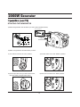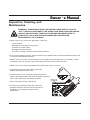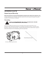
1
WARNING! To Reduce The Risk Of Injury, User
Must Read And Understand Instruction Manual.
2000W Generator
Topic
Page
Limited Warrant y
3
S a fet y G u i d e l i n e s
5
G e n e r a l Pr e c a u t i o n s
6
Battery
15
Assembly
16
Operation
17
I n s p e c t i o n, Cl e a n i n g a n d M a i n te n a n c e
21
Installation
23
Specifications
25
G e n e r a l Pa r t s L i s t i n g
26
WARNING! READ AND UNDERSTAND ALL SAFETY PRECAUTIONS
IN THIS MANUAL BEFORE OPERATING. FAILURE TO COMPLY WITH
INSTRUCTIONS IN THIS MANUAL COULD RESULT IN PERSONAL
INJURY, PROPERTY DAMAGE, AND/ OR VOIDING OF YOUR
WARRANTY. STEELE® WILL NOT BE LIABLE FOR ANY
DAMAGE BECAUSE OF FAILURE TO FOLLOW THESE INSTRUCTIONS.
2
Owner s Manual
Limited Warranty
STEELE® warrants to the original purchaser who uses the product in a consumer
application (personal, residential or household usage) that all products covered under this
warranty are free from defects in material and workmanship for one year from the date of
purchase. All products covered by this limited warranty which are used in commercial applications
(i.e. income producing) are warranted to be free of defects in material and workmanship for
90 days from the date of original purchase. Products covered under this warranty include air
compressors, air tools, service parts, pressure washers and generators.
STEELE® will repair or replace, at STEELE®’s sole option, products or
components which have failed within the warranty period. Service will be scheduled according
to the normal work flow and business hours at the service center location, and the availability of
replacement parts. All decisions of STEELE® with regard to this limited warranty shall be final.
This warranty gives you specific legal rights, and you may also have other rights which vary from
state to state.
RESPONSIBILITY OF ORIGINAL PURCHASER (initial User):
To process a warranty claim on this product, DO NOT return item to the retailer. The product must
be evaluated by an Authorized Warranty Service Center. For the location of the nearest Authorized
Warranty Service Center contact the retailer or place of purchase.
Retain original cash register sales receipt as proof of purchase for warranty to work.
Use reasonable care in the operation and maintenance of the product as described in the Owner’s
Manual(s).
Deliver or ship the product to the Authorized Warranty Service Center. Freight costs, if any must
be paid by the purchaser.
If the purchaser does not receive satisfactory results form the Authorized Warranty Service Center,
the purchaser should contact STEELE®.
3
2000W Generator
Limited Warranty (cont d)
THIS WARRANTY DOES NOT COVER:
• Merchandise sold as reconditioned, used as rental equipment, or floor or display models.
• Merchandise that has become damaged or inoperative because of ordinary wear, misuse,
cold, heat, rain, excessive humidity, freeze damage, use of improper chemicals, negligence,
accident, failure to operate the product in accordance with the instructions provided in the
Owner’s Manual(s) supplied with the product, improper maintenance, the use of accessories or
attachments not recommended by All-Power America, or unauthorized repair or alterations.
• Repair and transportation costs of merchandise determine not to be defective.
• Costs associated with assembly, required oil, adjustments or other installation and start-up
costs.
• Expendable parts or accessories supplied with the product which are expected to become
inoperative or unusable after a reasonable period of use.
• Merchandise sold by All-Power America which has been manufactured by and identified as the
product of another company, such as gasoline engines. The product manufacturer’s warranty, if
any, will apply.
• ANY INCIDENTAL, INDIRECT OR CONSEQUENTIAL LOSS, DAMAGE, OR EXPENSE THAT
MAY RESULT FROM ANY DEFECTS, FAILURE OR MALFUNCTION OF THE PRODUCT IS
NOT COVERED BY THIS WARRANTY. Some states do not allow the exclusion, so it may not
apply to you.
• IMPLIED WARRANTIES, INCLUDING THOSE OF MERCHANTABILITY OR FITNESS FOR
A PARTICULAR PURPOSE, ARE LIMITED TO ONE YEAR FROM THE DATE OF ORIGINAL
PURCHASE. Some states do not allow limitations on how long an implied warranty lasts, so the
above limitations may not apply to you.
4
Owner s Manual
Safety Guidelines - Definitions
This manual contains important information that you need to know and
understand in order to protect YOUR SAFETY and to PREVENT
EQUIPMENT PROBLEMS. The following symbols help you recognize this
information. Please read the manual and pay attention to these sections.
Save These Important Safety Instructions!
Read and understand all of these safety instructions. Be sure to retain
them for future use.
WARNING! WARNINGS INDICATE A CERTAINTY OR STRONG
POSSIBILITY OF PERSONAL INJURY OR DEATH IF
INSTRUCTIONS ARE NOT FOLLOWED.
CAUTION: CAUTIONS INDICATE A POSSIBILITY OF
EQUIPMENT DAMAGE IF INSTRUCTIONS ARE NOT
FOLLOWED.
NOTE: NOTES GIVE HELPFUL INFORMATION
WARNING! IMPROPER OPERATION OR MAINTENANCE
OF THIS PRODUCT COULD RESULT IN SERIOUS INJURY
AND PROPERTY DAMAGE. READ AND UNDERSTAND ALL
WARNINGS AND OPERATING INSTRUCTIONS BEFORE USING
THIS EQUIPMENT. WHEN USING AIR TOOLS, BASIC SAFETY
PRECAUTIONS SHOULD ALWAYS BE FOLLOWED TO REDUCE
THE RISK OF PERSONAL INJURY.
5
2000W Generator
General Precautions
WARNING! FAILURE TO FOLLOW THESE INSTRUCTIONS CAN RESULT IN
SEVERE INJURY OR DEATH.
DANGER
Carbon Monoxide
Using a generator indoors WILL KILL YOU IN MINUTES.
Carbon Monoxide
Generator exhaust contains high levels of carbon monoxide (CO), a poisonous gas you cannot see
or smell. If you can smell the generator exhaust, you are breathing CO. But even If you cannot smell
the exhaust, you could be breathing CO.
· NEVER use a generator inside homes, garages, crawlspaces, or other partly enclosed areas. Deadly
levels of carbon monoxide can build up in these areas. Using a fan or opening windows and doors
does NOT supply enough fresh air.
· ONLY use a generator outdoors and far away from open windows, doors, and vents. These
openings can pull in generator exhaust.
Even when you use a generator correctly, CO may leak into the home. ALWAYS use a
battery-powered or battery-backup CO alarm in the home.
If you start to feel sick, dizzy, or weak after the generator has been running, move to fresh air RIGHT
AWAY. See a doctor. You could have carbon monoxide poisoning.
Gasoline and Oil
This product requires oil and fuel. Attempting to start the engine without oil will ruin
the engine and void the warranty. Work in well ventilated area. Keep cigarettes,
flames or sparks away from the work area or where gasoline is stored.
WARNING! GASOLINE IS EXTREMELY FLAMMABLE AND IS EXPLOSIVE
UNDER CERTAIN CONDITIONS. KEEP OUT OF REACH OF CHILDREN.
• Gasoline fuel and fumes are flammable and potentially explosive. Use proper fuel storage and
handling procedures. Always have multiple ABC class fire extinguishers nearby.
• Keep the generator and surrounding area clean at all times.
• Fuel or oil spills must be cleaned up immediately. Dispose of fluids and cleaning materials as per
any local, state, or federal codes and regulations. Store oily rags in a covered metal container.
• Never store fuel or other flammable materials near the generator.
6
Owner s Manual
General Precautions (cont’d)
Gasoline and Oil (cont’d)
• Do not smoke, or allow sparks, flames or other sources of ignition around the engine and fuel
tank. Fuel vapors are explosive.
• Keep grounded conductive objects, such as tools, away from exposed, live electrical parts and
connections to avoid sparking or arcing. These events could ignite fumes or vapors.
• Do not refill the fuel tank while the engine is running or while the engine is still hot. Do not
operate the generator with known leaks in the fuel system
• Excessive buildup of unburned fuel gases in the exhaust system can create a potentially
explosive condition. This buildup can occur after repeated failed start attempts, valve testing, or
hot engine shutdown. If this occurs, open exhaust system drain plugs, if equipped, and allow the
gases to dissipate before attempting to restart the generator.
• Use only engine manufacturer recommended fuel and oil.
Hot Components
WARNING! ENGINE AND EXHAUST SYSTEM PARTS BECOME VERY
HOT AND REMAIN HOT FOR SOME TIME AFTER THE ENGINE IS RUN. WEAR
INSULATED GLOVES OR WAIT UNTIL THE ENGINE AND EXHAUST SYSTEM
HAVE COOLED BEFORE HANDLING THESE PARTS.
7
2000W Generator
General Precautions (cont’d)
Work Area
• Keep your work area clean and well lit. Cluttered benches and dark areas invite accidents.
• Do not operate power tools in explosive atmospheres, such as in the presence of flammable
liquids, gases, or dust. Generators create sparks which may ignite the dust or fumes.
• Keep bystanders, children, and visitors away while operating a generator. Provide barriers or
shields as needed.
Electrical Safety
• Grounded tools must be plugged into an outlet properly installed and
grounded in accordance with all codes and ordinances. Never remove the
grounding prong or modify the plug in any way. Do not use any adapter plugs.
• Grounding provides a low-resistance path to carry electricity away from the
user in the event of an electrical malfunction.
• Double insulated tools are equipped with a polarized plug where one blade is wider than the
other. This plug fits in a polarized outlet only one way. If the plug does not fit fully in the outlet,
reverse the plug. If it still does not fit, contact a qualified electrician to install a polarized outlet.
Do not change the plug in any way. Double insulation eliminates the need for the three-wire
grounded power cord and grounded power supply system.
• Avoid body contact with grounded surfaces such as pipes, radiators, ranges, and refrigerators.
There is an increased risk of electric shock if your body is grounded.
• Do not expose generator to rain or wet conditions. Water entering a generator will increase the
risk of electric shock.
• Do not abuse the power cord. Keep power cords away from heat, oil, sharp edges, or moving
parts. Replace damaged power cords immediately. Damaged power cords increase the risk of
electric shock.
• When operating a power tool outside, use an outdoor extension cord marked “W-A” or “W”.
These extension cords are rated for outdoor use, and reduce the risk of electric shock.
8
Owner s Manual
General Precautions (cont’d)
Electrical Safety (cont’d)
• All connections and conduits from the generator to the load must only be installed by trained and
licensed electricians, and in compliance with all relevant local, state, and federal electrical
codes and standards, and other regulations where applicable.
• The generator must be earth-grounded for fixed installations in accordance with all relevant
electrical codes and standards before operation.
• Do not attempt to connect or disconnect load connections while standing in water, or on wet or
soggy ground.
• Do not touch electrically energized parts of the generator and interconnecting cables or
conductors with any part of the body, or with any non-insulated conductive object.
• Connect the generator only to a load or electrical system (110/120 volt) that is compatible with
the electrical characteristics and rated capacities of the generator.
• Before servicing equipment powered by the generator, disconnect the equipment from its power
input.
• Keep all electrical equipment clean and dry. Replace any wiring where the insulation is cracked,
cut abraded or otherwise degraded. Replace terminals that are worn, discolored, or corroded.
Keep terminals clean and tight.
• Insulate all connections and disconnected wires.
• Guard against electric shock. Prevent body contact with grounded surfaces such as pipes,
radiators, ranges, and refrigerator enclosures.
Personal Safety
• Stay alert. Watch what you are doing, and use common sense when operating a generator. Do
not use generator while tired or under the influence of drugs, alcohol, or medication. A moment
of inattention while operating generators may result in serious personal injury.
• Dress properly. Do not wear loose clothing or jewelry. Contain long hair. Keep your hair, clothing,
and gloves away from moving parts. Loose clothes, jewelry, or long hair can be caught in
moving parts.
9
2000W Generator
General Precautions (cont’d)
Personal Safety (cont’d)
• Avoid accidental starting. Make sure the power switch is in its “OFF” position, and disconnect
the spark plug wire when not in use.
• Remove adjusting keys or wrenches before turning the generator on. A wrench or a key that is
left attached to a rotating part of the generator may result in personal injury.
• Do not overreach. Keep proper footing and balance at all times.
• Use safety equipment. Always wear eye protection. Wear ANSI approved safety impact eye
goggles. Dust mask, non-skid safety shoes, hard hat, or hearing protection must be used for
appropriate conditions.
• Do not force the generator. Use the correct generator for your application. The correct generator
will do the job better and safer at the rate for which it is designed.
• Do not use the generator if the power switch does not turn it on or off. Any generator that cannot
be controlled with the power switch is dangerous and must be replaced.
Generator Use and Care
Make sure the power switch is in its “OFF” position and disconnect the spark plug wire before
making any adjustment, changing accessories, or storing the generator. Such preventive safety
measures reduce the risk of starting the generator accidentally.
Store idle generators out of reach of children and other untrained persons. Generators are
dangerous in the hands of untrained users.
Maintain generators with care. Do not use damaged generator. Tag damaged generators “Do not
use” until repaired.
Check for misalignment or binding of moving parts, breakage of parts, and any other condition that
may affect the generator’s operation. If damaged, have the generator serviced before using. Many
accidents are caused by poorly maintained generators.
Use only accessories that are recommended by the manufacturer for your model. Accessories that
may be suitable for one generator may become hazardous when used on another generator.
10
Owner s Manual
General Precautions (cont’d)
Servicing
Maintain labels and name plates on the generator and engine. These carry important information.
If unreadable or missing, contact All Power America immediately for a replacement.
Generator service must be performed only qualified repair personnel. Service or maintenance
performed by unqualified personnel could result in a risk of injury.
When servicing a generator, use only identical replacement parts. Follow all appropriate
instructions in this manual. Use of unauthorized parts or failure to follow maintenance instructions
may create a risk of electric shock or injury.
Heart Pacemakers
WARNING! PEOPLE WITH PACEMAKERS SHOULD CONSULT THEIR
PHYSICIAN(S) BEFORE USING THIS PRODUCT. ELECTROMAGNETIC
FIELDS IN CLOSE PROXIMITY TO A HEART PACEMAKER COULD CAUSE
INTERFERENCE TO OR FAILURE OF THE PACEMAKER.
Installation
• Ensure installation meets all applicable safety, and local and national electrical codes. Have
installation performed by a qualified, licensed electrician and building contractor.
• All electrical work, including the earth-ground connection, should be completed by a licensed
electrician.
• Any separate fuel storage or generator supply facility must be built or installed in full compliance
with all relevant local, state, and federal regulations.
11
2000W Generator
General Precautions (cont’d)
Installation (cont’d)
• If the generator is installed outdoors, it must be weatherproofed and should be soundproofed. It
should not be run outdoors without protection to the generator and wiring conduit.
• The generator weighs 48 lbs. Two or more people should assist when moving or lifting this
product. Never lift the generator using the engine or alternator lifting lugs. Connect lifting
equipment to the frame of the generator
• Before lifting the generator, ensure the lift rigging and supporting structure are in good
condition, and are rated to lift such a load.
• Keep all personnel away from the suspended generator during relocating.
• The supporting floor/ground surface should be level and strong enough to safely hold the weight
of the generator. If the floor/grounded surface is not level, strong cross members should be
placed under the full length of the generator frame at its low side.
• For trailer installation, the generator should be mounted on the center point of the trailer, over
the wheels. The trailer must be capable of supporting the weight of the generator and all
contents (tools, etc.)
• Install sound-and weather-proofing only when it is not raining or snowing to avoid trapping
moisture within the generator’s area.
Mechanical
• Always make sure the power switch is in its “OFF” position. Disconnect the spark plug wire, and
allow the engine to completely cool before carrying out maintenance.
• Check for damaged parts. Before using the generator, any part that appears damaged should
be carefully checked to determine that it will operate properly and perform its intended function.
Check for alignment and binding of moving parts, any broken parts or mounting fixtures, and any
other condition that may affect proper operation technician.
• The generator is designed with guards for protection from moving parts. In any case, care must
still be taken to protect personnel and equipment from other mechanical hazards when working
around the generator.
12
Owner s Manual
General Precautions (cont’d)
Mechanical (cont’d)
• Do not operate the generator with safety guards removed. While the generator is running, do not
attempt to reach around the safety guard for maintenance or any other reason.
• Keep hands, arms, long hair, loose clothing, and jewelry away from moving parts. Be aware that
when engine parts are moving fast they cannot be seen clearly.
• Keep access doors on enclosures closed and locked when access is not required.
• When working on or around the generator always wear protective clothing including ANSI
approved safety gloves, safety eye goggles, and safety hat.
• Do not alter or adjust any part of the generator that is assembled and supplied by the
manufacturer.
• Always follow and complete scheduled engine and generator maintenance.
Chemicals
• Avoid contact with hot fuel, oil, exhaust fumes, and hot solid surfaces.
• Avoid body contact with fuels, oils, and lubricants used in the generator. If swallowed, seek
medical treatment immediately. Do not induce vomiting if fuel is swallowed. For skin contact,
immediately wash with soap and water. For eye contact, immediately flush eyes with clean water
and seek medical attention.
Noise
• Prolonged exposure to noise levels above 85 DBA is hazardous to hearing. Always wear ANSI
approved ear protection when operating or working around the generator when it is running.
13
2000W Generator
General Precautions (cont’d)
Extension Cord
If an extension cord (not included) is used, make sure to use only UL approved cords having the
correct gauge and length according to the following table:
N ame plate Amps (@
full load)
0'-50'
0 - 5 16 AWG
5.1 - 8 16 AWG
8.1 - 12
14 AWG
Cord Le ngths
50'-100'
16 AWG
14 AWG
12 AWG
14
100'-150'
12 AWG
10 AWG
-
150'-200'
12 AWG
-
Owner s Manual
Battery
This product does not need a battery.
15
2000W Generator
Assembly
No assembly required for this product.
16
Owner s Manual
Operation
Fuel Tank
Handle
Choke
Spark Plug &
Oil Fill
Access Panel
Carburetor Access Panel
Control Panel
Engine Switch
Starter Grip
NOTE: THE PARTS LISTED ABOVE ARE HELPFUL FOR LOCATING THE CONTROLS
MENTIONED BELOW.
CAUTION: Prior To First Using The Generator, The Engine
Must Be Filled With A High Quality Sae 10w-30 Grade Engine
Oil. To Do So Unscrew And Remove The Engine’s Oil Dipstick
Located At The Bottom Of The Engine Crankcase. Fill The
Engine’s Crankcase Until The Oil Level Is Level With The
Upper Marked Line On The Dipstick. Then, Screw The Dipstick
Back Into The Oil Fill Hole.
SAE Viscosity Grades
30
ENGINE OIL RECOMMENDATIONS
Oil is a major factor affecting performance and service life. Use
4-stroke automotive detergent oil.
SAE 10W 30 is recommended for general use. Other viscosities
shown in the chart may be used when the average temperature in
your area is within the recommended range.
10W-30
5W-30
-20
0
-20 -10
20
40
60
80 100°F
0
10
20
30
40°C
AMBIENT TEMPERATURE
Before Starting the Generator
1. Check that the engine power switch is in its “OFF” position (see diagram on next page).
2. Before the first use, remove the fuel tank cap and fill the fuel tank with unleaded gasoline. When
fueling, be sure that the fuel strainer is in place. Replace the fuel tank cap. Thereafter, check
the engine’s fuel gauge for the amount of unleaded gasoline in the fuel tank. If necessary, refill
the fuel tank with unleaded gasoline. The generator must be turned off and cooled down before
refilling the fuel tank.
17
2000W Generator
O
STARTING THE GENERATOR
1) Make sure generator has oil before you start. (see illustration below)
Oil Fill Cap/Dipstick
Upper Limit
Spark Plug &
Oil Fill
Access Panel
Lower Limit
2) Make sure generator has fuel before you start.
3) Turn the fuel valve to the “ON” position
4) Pull the choke out to the “START” position.
5) Pull the pull start until you feel some tension,
then pull swiftly until generator starts.
6) Push in the choke to the “RUN” position.
18
Owner s Manual
Operation (cont’d)
Powering 120 Volt AC Tools And Equipment:
1. Prior to powering tools and equipment, make sure the generator’s rated voltage, and amperage
capacity (120V/AC @ 13 AMPs) is adequate to supply all electrical loads that the unit will
power. If powering exceeds the generator’s capacity, it may be necessary to group one or more
of the tools and/or equipment for connection to a separate generator.
2. Once the generator is running, simply connect the power cords of 120 volt AC powered
tools and equipment into the 120 volt AC outlets.
NOTE: THE GENERATOR FEATURES AN OVERLOAD PROTECTION DEVICE
WHICH WILL SHUT DOWN GENERATOR IF IT OVERLOADS. IF THIS OCCURS
MAKE SURE TO DISCONNECT ALL ELECTRICAL POWER CORDS CONNECTED
TO THE GENERATOR BEFORE YOU START GENERATOR.
3. Disconnect all electrical powered tools and equipment from the generator’s 110/120 volt AC
duel outlets.
4. After the engine and generator have completely cooled, store generator in a safe, clean, dry
location (if not already installed).
19
2000W Generator
Operation (cont’d)
Powering 12 Volt DC tools and Equipment:
1. Prior to powering tools and equipment, make sure the generator’s rated voltage, and amperage
capacity (12V/DC @ 8.3 AMPs) is adequate to supply all electrical loads that the unit will
power. If powering exceeds the generator’s capacity, it may be necessary to group one or more
of the tools and/or equipment for connection to a separate generator.
2. Connect the power cord of a 12V DC powered tool or equipment to the DC Terminals.
3. Start and run the engine as described above
4. When finished using the generator, turn the fuel valve to its “OFF” position. Turn
the fuel valve to its “OFF” position.
5. Disconnect the electrical powered tools’ power cord from the generator’s DC terminals.
6. After the engine and generator have completely cooled, store the generator in a safe, clean, dry
location (if not already installed in one).
20
Owner s Manual
Inspection, Cleaning, and
Maintenance
WARNING! ALWAYS MAKE SURE THE ENGINE POWER SWITCH IS IN ITS
“OFF” POSITION. DISCONNECT THE SPARK PLUG WIRE FROM THE ENGINE.
AND ALLOW SUFFICIENT TIME FOR THE ENGINE AND GENERATOR TO
COMPLETELY COOL BEFORE PERFORMING ANY INSPECTIONS,
MAINTENANCE, OR CLEANING.
• Before each use, inspect the generator. Check for:
-
Loose screws
Misaligned or binding moving parts
Cracked or broken parts
Damaged electrical wiring
Any other condition that may affect safe operation.
• If an engine problem occurs, have it checked by a qualified service technical before further use.
Do not use damaged equipment.
• Before each use, make sure the engine’s oil and gas levels are adequate. If necessary, fill the
crankcase until the oil level is even with the oil hill hole and/or fill the fuel tank.
• Before each use, remove all debris with a soft brush, rag, or vacuum.
• Lubricate all moving parts using a premium
quality, lightweight machine oil.
• First 20 hours of use, drain the old engine oil and
replace with high quality SAE 10W-30 grade engine oil.
This is only required for the break-in period.
• Every 100 hours of use, change oil.
• For long term storage, either drain fuel into
suitable container or add a fuel preservative/
stabilizer (not included) to prevent fuel
breakdown.
21
Owner s Manual
MAINTENANCE SCHEDULE
REGULAR SERVICE PERIOD (3)
Perform at every indicated month or
operating hour interval, whichever comes
first.
Engine Oil
Check level
Change
Air filter
Check
Clean
Sediment cup
Clean
Spark plug
Check-adjust
Replace
Spark arrester
Clean
Valve clearance
Check-adjust
Combustion chamber
Each
Use
Clean
Fuel tank and filter
Clean
Fuel tube
Check
First
month
or
20 Hrs.
Every
3
months
or
50 Hrs.
Every
6
months
or
100 Hrs.
Every
year
or
300 Hrs.
After every 500 Hrs.
Every 2 years (Replace if necessary)
1) Service more frequently when used in dusty areas.
2) These items should be serviced by your servicing dealer, unless you have the proper tools
and are mechanically proficient.
3) For commercial use, log hours of operation to determine proper maintenance intervals.
22
2000W Generator
Installation
Electrical and other permits may be required for the installation of emergency power systems.
Investigate your local building and electrical codes before installing this unit. Installation must be
completed by licensed contractors.
WARNING! THE GENERATOR WEIGHS APPROXIMATELY 48 POUNDS. USE
CARE AND THE PROPER LIFTING OR HOISTING EQUIPMENT WHEN MOVING
IT TO THE INSTALLATION LOCATION. ALWAYS CONNECT HOIST LINES TO
THE FRAME OF THE GENERATOR.
General Location
• Make sure to locate and install the generator outdoors where cooling air is readily available.
• Install the generator so that the air inlets and outlets are not blocked by obstructions such as
bushes, trees, or snow drifts. Locating it in the path of heavy winds or snowdrifts may require
the placement of a barrier for protection. In normal weather conditions, the air vent should face
the prevailing wind direction.
• Install the generator on a concrete slab or other area where rain drainage or flood waters can
not reach it.
• Generator placement should allow four feet of access to all sides for maintenance.
• Place the generator as close as possible to the electrical tools and equipment being powered to
reduce the length of extension cords.
23
Owner s Manual
Installation (cont’d)
Supporting and Mounting
Mount the generator on a concrete slab capable of supporting the weight of the generator. The
slab must extend on all sides beyond the frame by at least one foot. Contact a cement contractor
for slab specifications if necessary. Attach the frame to the concrete slab using 3/8” diameter
expansion anchor bolts (not supplied).
Grounding
NOTE: IT IS RECOMMENDED THAT ONLY A TRAINED AND LICENSED
ELECTRICIAN PERFORM THIS PROCEDURE
Connect a #6 AWG grounding wire (not included) from the ground connector on the
generator power panel (picture below) to a grounding rod (picture below). It must be driven
at least 24” deep into the earth (Soil). The grounding rod must be an earth-driven copper or
brass (electrode) which can adequately ground the generator.
Brass Rod (electrode)
Connect Grounding Wire Here
24
2000W Generator
(APG3102 & APG3102C)
120V AC @ 13A,60Hz
Current output
Continuous/rated wattage
1600
Peak wattage
2000
Two 120V AC with 3-spring grounded
Outlets
DC e ec ic
12V DC @ 8.3A
Current output
Horse power
3
Type
4 stroke,OHV,air cooled,recoil start
Displacement
Oil Capacity
0.63quart (0.6 liters)
Approved
SP-GG200D-EPA
Type
Unleaded gasoline
Capacity
0.814 Gallons (3.081 Liters)
Running time @ 3.081L Fuel
4 hour
Fuel gauge
Not included
Net Weight
48lbs
W
25
2000W Generator
Cylinder head system assy.
A
APA Part No.
Description
Part. No
APG3102-A-01-JD
HEAD COVER COMP. BOLT
JF156-A-01
APG3102-A-02-JD
FLANGE BOLT (M6X 16)
JF156-A-02
APG3102-A-03-JD
ROCKER ARM ASSY.
JF156-A-03
APG3102-A-04-JD
HEAD COVER COMP.
JF156-A-04
APG3102-A-05-JD
HEAD COVER PACKING
JF156-A-05
APG3102-A-06-JD
FLANGE BOLT (M8X 55)
JF156-A-06
APG3102-A-07-JD
SPARK PLUG
JF156-A-07
APG3102-A-08-JD
EXHAUST PIPE STUD BOLT
JF156-A-08
APG3102-A-09-JD
CYLINDER HEAD COMP.
JF156-A-09
APG3102-A-10-JD
CARBURETOR STUD BOLT
JF156-A-10
APG3102-A-11-JD
CYLINDER HEAD SEALING PAD
JF156-A-11
APG3102-A-12-JD
DOWEL PIN (?10×?12×20)
JF156-A-12
APG3102-A-13-JD
AIR CLEANER STAY
JF156-A-13
26
2000W Generator
Cylinder barrel
B
APA Part No.
Description
Part. No
APG3102-B-01-JD
FLANGE BOLT (M6X 16)
JF156-B-01
APG3102-B-02-JD
BALL BEARING (6203)
JF156-B-02
APG3102-B-03-JD
OIL LEVEL SWITCH ASSY.
JF156-B-03
APG3102-B-04-JD
0-RING (14mm)
JF156-B-04
APG3102-B-05-JD
FLANGE NUT (MIO)
JF156-B-05
APG3102-B-06-JD
DRAIN PLUG BOLT
JF156-B-06
APG3102-B-07-JD
DRAIN PLUG WASHER
JF156-B-07
APG3102-B-08-JD
CRANK CASE
JF156-B-08
APG3102-B-09-JD
OIL SEAL ( ?17×?30×6)
JF156-B-09
APG3102-B-10-JD
CORD CLAMPER
JF156-B-10
APG3102-B-11-JD
FLANGE BOLT (M6X12)
JF156-B-11
27
2000W Generator
Crankcase cover system assy.
C
APA Part No.
Part. No
Description
APG3102-C-01-JD
OIL SCALE
JF156-C-01
APG3102-C-02-JD
OIL SCALE SEAL RING
JF156-C-02
APG3102-C-03-JD
OIL SCALE GOD
JF156-C-03
APG3102-C-04-JD
OIL SCALE SEAL RING
JF156-C-04
APG3102-C-05-JD
FLANGE BOLT (M6X25)
JF156-C-05
APG3102-C-06-JD
DOWEL PIN
JF156-C-06
APG3102-C-07-JD
CRANKCASE COVER
JF156-C-07
APG3102-C-08-JD
CRANKCASE COVER PAD
JF156-C-08
APG3102-C-09-JD
BALL BEARING (6303)
JF156-C-09
APG3102-C-10-JD
FLANGE BOLT (M6X16)
JF156-C-10
28
2000W Generator
Crankshaft system assy.
D
APA Part No.
Description
Part. No
APG3102-D-Ol-JD
CRANKSHAFT COMP.
JF156-D-01
APG3102-D-02-JD
SPECIAL WOODRUFF KEY
JF156-D-02
29
2000W Generator
Piston and connecting rod system assy.
E
APA Part No.
Description
Part. No
APG3102-E-01-JD
COMPRESSION RING A
JF156-E-01
APG3102-E-02-JD
COMPRESSION RING B
JF156-E-02
APG3102-E-03-JD
OIL RING A
JF156-E-03
APG3102-E-04-JD
OIL RING B
JF156-E-04
APG3102-E-05-JD
PISTON PIN CLIP
JF156-E-05
APG3102-E-06-JD
PISTON
JF156-E-05
APG3102-E-07-JD
PISTON PIN
JF156-E-06
APG3102-E-08-JD
CONNECTING ROD
JF156-E-07
APG3102-E-09-JD
CONNECTING COVER
JF156-E-08
APG3102-E-10-JD
CONNECTING ROD BOLT
JF156-E-09
30
2000W Generator
Camshaft Valve system assy.
F
APA Part No.
Description
Part. No
APG3102-F-01-JD
CAMSHAFT
JF156-F-01
APG3102-F-02-JD
VALVE LIFTER
JF156-F-02
APG3102-F-03-JD
ROD PUSH
JF156-F-03
APG3102-F-04-JD
EX. VALVE
JF156-F-04
APG3102-F-05-JD
IN. VALVE
JF156-F-05
APG3102-F-06-JD
VALVE SPRING SEAT
JF156-F-06
APG3102-F-07-JD
VALVE SPRING
JF156-F-07
31
2000W Generator
Recoil starter system assy.
1
G
APA Part No.
Description
Part. No
APG3102-G-01-JD
RECOIL STARTER ASSY.
JF156-G-01
APG3102-G-02-JD
SETTING SCREW
JF156-G-02
APG3102-G-03-JD
SPRING RETAINER
JF156-G-03
APG3102-G-04-JD
PLATEN SPRING
JF156-G-04
APG3102-G-05-JD
STARTER DETENT
JF156-G-05
APG3102-G-06-JD
DETENT SPRING
JF156-G-06
APG3102-G-07-JD
RECOIL STARTER REEL
JF156-G-07
APG3102-G-08-JD
START RETURN SPRING
JF156-G-08
APG3102-G-09-JD
RECOIL STARTER CASE COMP.
JF156-G-09
APG3102-G-10-JD
RECOIL STARTER ROPE
JF156-G-10
APG3102-G-11-JD
STARTER KNOB
JF156-G-11
APG3102-G-12-JD
FLANGE BOLT (M6X8)
JF156-G-12
32
2000W Generator
Fan cover system assy.
H
APA Part No.
Description
Part. No
APG3102-H-01-JD
CORD GROMMENT A
JF156-H-01
APG3102-H-02-JD
FAN COVER COMP.
JF156-H-02
APG3102-H-03-JD
BRAKER
JF156-H-03
APG3102-H-04-JD
FLANGE BOLT (M6X12)
JF156-H-04
APG3102-H-05-JD
CORD GROMMENT B
JF156-H-05
33
2000W Generator
Carburetor system assy.
I
APA Part No.
Description
Part. No
APG3102-I-01-JD
STEPPER MOTOR
JF156-I-01
APG3102-I-02-JD
INTAKE PIPE GASKET
JF156-I-02
APG3102-I-03-JD
CARBURETOR INSULATING PLATE
JF156-I-03
APG3102-I-04-JD
CARBURETOR ASSY.(FOR APG3102) JF156-I-04
APG3102C-I-04-JD
CARBURETOR ASSY.(FOR APG3102C)JF156-I-04
APG3102-I-05-JD
TUBE CLIP
JF156-I-05
APG3102-I-06-JD
TUBE
JF156-I-06
APG3102-I-07-JD
CARBURETOR IRON GASKET
JF156-I-07
APG3102-I-08-JD
BREAKER
JF156-I-08
34
2000W Generator
Flywheel system Assy.
5
4
3
J
APA Part No.
Description
Part. No
APG3102-J-01-JD
FLYWHEEL
JF156-J-01
APG3102-J-02-JD
FLANGE BOLT (M6 X16)
JF156-J-02
APG3102-J-03-JD
STARTER PULLEY
JF156-J-03
APG3102-J-04-JD
COOLING FAN
JF156-J-04
APG3102-J-05-JD
FLYWHEEL NUT
JF156-J-05
35
2000W Generator
Ignition System Assy.
K
APA Part No.
Description
Part. No
APG3102-K-01-JD
FLANGE BOLT (M6 X 25)
JF156-K-01
APG3102-K-02-JD
NOISE SUPPERSSOR CAP ASSY.
JF156-K-02
APG3102-K-03-JD
INGITION GOIL ASSY.
JF156-K-03
APG3102-K-04-JD
STOP SWITCH CORD
JF156-K-04
APG3102-K-05-JD
TRIGGER
JF156-K-05
APG3102-K-06-JD
FLANGE BOLT (M6X12)
JF156-K-06
36
2000W Generator
Control box assy.
8
L
APA Part No.
Description
Part. No
APG3102-L-01-JD
RECTIFIER
JF156-L-01
APG3102-L-02-JD
FLANGE BOLT (M5 X16)
JF156-L-02
APG3102-L-03-JD
CONTROL PANEL COMP.
JF156-L-03
APG3102-L-04-JD
INDICATE LAMP
JF156-L-04
APG3102-L-05-JD
120V RECEPTACLE(Ru-22)
JF156-L-05
APG3102-L-06-JD
CHOKE LEVER
JF156-L-06
APG3102-L-07-JD
DC 12V OUTPUT
JF156-L-07
APG3102-L-08-JD
EARTH TERMINAL SET
JF156-L-08
37
2000W Generator
TRANSDUCER ASSY.
M
APA Part No.
Description
Part. No
APG3102-M-01-JD
TRANSDUCER
JF156-M-01
APG3102-M-02-JD
FLANGE NUT (M6)
JF156-M-02
APG3102-M-03-JD
CONTROL TRANSDUCER RUBBER
JF156-M-03
APG3102-M-04-JD
SPRING WASHER
JF156-M-04
APG3102-M-05-JD
FLANGE BOLT (M6×30)
JF156-M-05
38
2000W Generator
Muffler System Assy.
8
8
11
10
9
1
1
N
Part. No
APA Part No.
Description
APG3102-N-01-JD
FLANGE BOLT (M6X12)
JF156-N-01
APG3102-N-02-JD
FLANGE NUT (M6)
JF156-N-02
APG3102-N-03-JD
MUFF. OUTER PROTECTOR
JF156-N-03
APG3102-N-04-JD
MUFFLER COMP.( APG3102 ONLY)
JF156-N-04
APG3102C-N-04-JD
MUFFLER COMP.
JF156-N-04B
APG3102-N-05-JD
EX. PIPE GASKET
JF156-N-05
APG3102-N-06-JD
EX PIPE COMP.
JF156-N-06
APG3102-N-07-JD
MUFFLER COMP,
JF156-N-07
APG3102-N-08-JD
FLANGE BOLT (M6X25)
JF156-N-08
APG3102C-N-09-JD
GASKET ( APG3102C ONLY)
JF156-N-09
APG3102C-N-10-JD
AIR VALVE ( APG3102C ONLY)
JF156-N-10
APG3102C-N-11-JD
AIR PIPE ( APG3102C ONLY)
JF156-N-11
39
2000W Generator
Air cleaner
O
Part. No
APA Part No.
Description
APG3102-O-01-JD
AIR CLEANER CASE COMP (FOR APG3102)
APG3102C-O-01-JD
AIR CLEANER CASE COMP (FOR APG3102C) JF156-O-01B
JF156-O-01
APG3102-O-02-JD
AIR CLEANER SEAL
JF156-O-02
APG3102-O-03-JD
AIR CLEANER ELEMENT
JF156-O-03
APG3102-O-04-JD
AIR CLEANER COVER
JF156-O-04
APG3102-O-05-JD
FLANGE BOLT
JF156-O-05
40
2000W Generator
Fuel tank system assy.
9
3
P
APA Part No.
Description
Part. No
APG3102-P-01-JD
FUEL TANK COMP. (FOR APG3102)
JF156-P-01
APG3102C-P-01-JD
FUEL TANK COMP.(FOR APG3102C)
JF156-P-01B
APG3102-P-02-JD
FLANGE BOLT
JF156-P-02
APG3102-P-03-JD
FUEL FILLER CAP COMP (FOR APG3102)
JF156-P-03
APG3102C-P-03-JD
FUEL FILLER CAP COMP (FOR APG3102C) JF156-P-03B
APG3102-P-04-JD
TUBE CLIP
JF156-P-04
APG3102-P-05-JD
FUEL TUBE
JF156-P-05
APG3102-P-06-JD
FUEL SWITCH
JF156-P-06
APG3102-P-07-JD
FLANGE NUT (M6)
JF156-P-07
APG3102-P-08-JD
FUEL FILTER
JF156-P-08
APG3102C-P-09-JD
OVERFLOW VALVE
JF156-P-09
41
2000W Generator
Shroud assy.
Q
APA Part No.
Description
Part. No
APG3102-Q-01-JD
CYLINDER HEAD AIR COURSE COVER
JF156-Q-01
APG3102-Q-02-JD
TOPE AIR COURSE COVER
JF156-Q-02
APG3102-Q-03-JD
SIDE AIR COURSE COVER
JF156-Q-03
APG3102-Q-04-JD
BOTTOM AIR COURSE COVER
JF156-Q-04
42
2000W Generator
Generator assy.
R
APA Part No.
Description
Part. No
APG3102-R-01-JD
STATOR ASSY.
JF156-R-01
APG3102-R-02-JD
FLANGE BOLT (M5X40)
JF156-R-01
APG3102-R-03-JD
ROTOR COMP.
JF156-R-03
43
2000W Generator
Enclosure Assembly
S
44
2000W Generator
Enclosure Assembly
S
APA Part No.
Description
Part. No
APG3102-S-01-JD
COVER BOARD A
JF156-S-01
APG3102-S-02-JD
COVER BOARD B
JF156-S-02
APG3102-S-03-JD
MOBILE WHEEL
JF156-S-03
APG3102-S-04-JD
BOTTOM RUBBER
JF156-S-04
APG3102-S-05-JD
ENCLOSURE(LEFT)
JF156-S-05
APG3102-S-06-JD
RUBBER CAP
JF156-S-06
APG3102-S-07-JD
BASE PLATE
JF156-S-07
APG3102-S-08-JD
FRONT COVER
JF156-S-08
APG3102-S-09-JD
REAR COVER
JF156-S-09
APG3102-S-10-JD
SHOCK ABSORPTION PAD
JF156-S-10
APG3102-S-11-JD
BUSHING
JF156-S-11
APG3102-S-12-JD
TRANSDUCER MOUNTING FRAME
JF156-S-12
APG3102-S-13-JD
BUSHING
JF156-S-13
APG3102-S-14-JD
SHOCK ABSORPTION PAD
JF156-S-14
APG3102-S-15-JD
ENCLOSURE(RIGHT)
JF156-S-15
APG3102-S-16-JD
PULLING CORD SUPPORT
JF156-S-16
APG3102-S-17-JD
COVER BOARD C
JF156-S-17
APG3102-S-18-JD
SPILLED FUEL COLLECTION PLATE JF156-S-18
45
2000W Generator
Frame Assembly
T
46
2000W Generator
Frame Assembly
T
APA Part No.
Description
Part. No
APG3102-T-01-JD
SUPPORT FRAME(RIGHT)
JF156-T-01
APG3102-T-02-JD
SUPPORT FRAME(LEFT)
JF156-T-02
APG3102-T-03-JD
BOLT(M6 x 105)
JF156-T-03
APG3102-T-04-JD
SHOCK ABSORPTION PAD
JF156-T-04
APG3102-T-05-JD
BUSHING
JF156-T-05
APG3102-T-06-JD
WHEEL SHAFT
JF156-T-06
APG3102-T-07-JD
SHAFT BUSHING
JF156-T-07
APG3102-T-08-JD
SHOCK ABSORPTION
JF156-T-08
APG3102-T-09-JD
NUT
JF156-T-09
APG3102-T-10-JD
BOLT(M6 x 135)
JF156-T-10
APG3102-T-11-JD
SHOCK ABSORPTION PAD
JF156-T-11
APG3102-T-12-JD
BUSHING
JF156-T-12
APG3102-T-13-JD
BOLT(M6 x 185)
JF156-T-13
APG3102-T-14-JD
SHOCK ABSORPTION PAD
JF156-T-14
APG3102-T-15-JD
BUSHING
JF156-T-15
APG3102-T-16-JD
NUT
JF156-T-16
47
2000W Generator
Handle Assembly
U
APA Part No.
Description
Part. No
APG3102-U-01-JD
ARCHED HANDLE
JF156-U-01
APG3102-U-02-JD
HANDLE AXES
JF156-U-02
APG3102-U-03-JD
U
HANDLE
JF156-U-03
APG3102-U-04-JD
C
HANDLE
JF156-U-04
APG3102-U-05-JD
D
HANDLE
JF156-U-05
APG3102-U-06-JD
REPLACEMENT SPRING
JF156-U-06
APG3102-U-07-JD
RUBBER BUSHING
JF156-U-07
APG3102-U-08-JD
RACHET BUSHING
JF156-U-08
48
2000W Generator
Carbon Canister assy. (APG3102 ONLY)
1
2
5
2
4
3
2
6
V
2
APA Part No.
Description
Part. No
APG3102C-V-01-JD
BRACKER A
JF156-V-01
APG3102C-V-02-JD
FLANGE BOLT (M6X12)
JF156-V-02
APG3102C-V-03-JD
FUEL TUBE A
JF156-V-03
APG3102C-V-04-JD
CARBON CANISTER
JF156-V-04
APG3102C-V-05-JD
FUEL TUBE B
JF156-V-05
APG3102C-V-06-JD
BRACKER B
JF156-V-06
49
2000W Generator
50